EP3848267B1 - Vehicle fitted with shock absorbers for transporting passengers on a track with variable slope and facility comprising said vehicle - Google Patents
Vehicle fitted with shock absorbers for transporting passengers on a track with variable slope and facility comprising said vehicle Download PDFInfo
- Publication number
- EP3848267B1 EP3848267B1 EP21150710.8A EP21150710A EP3848267B1 EP 3848267 B1 EP3848267 B1 EP 3848267B1 EP 21150710 A EP21150710 A EP 21150710A EP 3848267 B1 EP3848267 B1 EP 3848267B1
- Authority
- EP
- European Patent Office
- Prior art keywords
- vehicle
- carriage
- cabin
- track
- shock absorber
- Prior art date
- Legal status (The legal status is an assumption and is not a legal conclusion. Google has not performed a legal analysis and makes no representation as to the accuracy of the status listed.)
- Active
Links
- 230000035939 shock Effects 0.000 title claims description 37
- 239000006096 absorbing agent Substances 0.000 title claims description 31
- 238000010521 absorption reaction Methods 0.000 claims description 8
- 238000009434 installation Methods 0.000 description 40
- 238000013016 damping Methods 0.000 description 31
- 230000001133 acceleration Effects 0.000 description 7
- 238000005096 rolling process Methods 0.000 description 6
- 230000007257 malfunction Effects 0.000 description 5
- 230000004913 activation Effects 0.000 description 4
- 240000008042 Zea mays Species 0.000 description 2
- 230000008859 change Effects 0.000 description 2
- 238000001514 detection method Methods 0.000 description 2
- 230000007246 mechanism Effects 0.000 description 2
- 230000021715 photosynthesis, light harvesting Effects 0.000 description 2
- 230000000750 progressive effect Effects 0.000 description 2
- 230000003213 activating effect Effects 0.000 description 1
- 230000001174 ascending effect Effects 0.000 description 1
- 210000000078 claw Anatomy 0.000 description 1
- 230000001276 controlling effect Effects 0.000 description 1
- 230000000694 effects Effects 0.000 description 1
- 230000017525 heat dissipation Effects 0.000 description 1
- 230000010354 integration Effects 0.000 description 1
- 239000000463 material Substances 0.000 description 1
- 230000009347 mechanical transmission Effects 0.000 description 1
- 238000012986 modification Methods 0.000 description 1
- 230000004048 modification Effects 0.000 description 1
- 230000001105 regulatory effect Effects 0.000 description 1
- 230000004044 response Effects 0.000 description 1
- 239000007787 solid Substances 0.000 description 1
- 230000001131 transforming effect Effects 0.000 description 1
- 230000001960 triggered effect Effects 0.000 description 1
Images


Classifications
-
- B—PERFORMING OPERATIONS; TRANSPORTING
- B61—RAILWAYS
- B61B—RAILWAY SYSTEMS; EQUIPMENT THEREFOR NOT OTHERWISE PROVIDED FOR
- B61B9/00—Tramway or funicular systems with rigid track and cable traction
-
- A—HUMAN NECESSITIES
- A63—SPORTS; GAMES; AMUSEMENTS
- A63G—MERRY-GO-ROUNDS; SWINGS; ROCKING-HORSES; CHUTES; SWITCHBACKS; SIMILAR DEVICES FOR PUBLIC AMUSEMENT
- A63G21/00—Chutes; Helter-skelters
-
- B—PERFORMING OPERATIONS; TRANSPORTING
- B61—RAILWAYS
- B61B—RAILWAY SYSTEMS; EQUIPMENT THEREFOR NOT OTHERWISE PROVIDED FOR
- B61B12/00—Component parts, details or accessories not provided for in groups B61B7/00 - B61B11/00
- B61B12/002—Cabins; Ski-lift seats
-
- B—PERFORMING OPERATIONS; TRANSPORTING
- B61—RAILWAYS
- B61B—RAILWAY SYSTEMS; EQUIPMENT THEREFOR NOT OTHERWISE PROVIDED FOR
- B61B12/00—Component parts, details or accessories not provided for in groups B61B7/00 - B61B11/00
- B61B12/02—Suspension of the load; Guiding means, e.g. wheels; Attaching traction cables
- B61B12/028—Cabin or seat suspension means
-
- B—PERFORMING OPERATIONS; TRANSPORTING
- B61—RAILWAYS
- B61B—RAILWAY SYSTEMS; EQUIPMENT THEREFOR NOT OTHERWISE PROVIDED FOR
- B61B12/00—Component parts, details or accessories not provided for in groups B61B7/00 - B61B11/00
- B61B12/10—Cable traction drives
-
- B—PERFORMING OPERATIONS; TRANSPORTING
- B61—RAILWAYS
- B61B—RAILWAY SYSTEMS; EQUIPMENT THEREFOR NOT OTHERWISE PROVIDED FOR
- B61B5/00—Elevated railway systems without suspended vehicles
-
- B—PERFORMING OPERATIONS; TRANSPORTING
- B61—RAILWAYS
- B61B—RAILWAY SYSTEMS; EQUIPMENT THEREFOR NOT OTHERWISE PROVIDED FOR
- B61B7/00—Rope railway systems with suspended flexible tracks
-
- B—PERFORMING OPERATIONS; TRANSPORTING
- B61—RAILWAYS
- B61C—LOCOMOTIVES; MOTOR RAILCARS
- B61C11/00—Locomotives or motor railcars characterised by the type of means applying the tractive effort; Arrangement or disposition of running gear other than normal driving wheel
- B61C11/02—Locomotives or motor railcars characterised by the type of means applying the tractive effort; Arrangement or disposition of running gear other than normal driving wheel tractive effort applied to cables or chains
-
- B—PERFORMING OPERATIONS; TRANSPORTING
- B61—RAILWAYS
- B61D—BODY DETAILS OR KINDS OF RAILWAY VEHICLES
- B61D1/00—Carriages for ordinary railway passenger traffic
-
- B—PERFORMING OPERATIONS; TRANSPORTING
- B61—RAILWAYS
- B61F—RAIL VEHICLE SUSPENSIONS, e.g. UNDERFRAMES, BOGIES OR ARRANGEMENTS OF WHEEL AXLES; RAIL VEHICLES FOR USE ON TRACKS OF DIFFERENT WIDTH; PREVENTING DERAILING OF RAIL VEHICLES; WHEEL GUARDS, OBSTRUCTION REMOVERS OR THE LIKE FOR RAIL VEHICLES
- B61F13/00—Rail vehicles characterised by wheel arrangements, not otherwise provided for
-
- B—PERFORMING OPERATIONS; TRANSPORTING
- B61—RAILWAYS
- B61F—RAIL VEHICLE SUSPENSIONS, e.g. UNDERFRAMES, BOGIES OR ARRANGEMENTS OF WHEEL AXLES; RAIL VEHICLES FOR USE ON TRACKS OF DIFFERENT WIDTH; PREVENTING DERAILING OF RAIL VEHICLES; WHEEL GUARDS, OBSTRUCTION REMOVERS OR THE LIKE FOR RAIL VEHICLES
- B61F5/00—Constructional details of bogies; Connections between bogies and vehicle underframes; Arrangements or devices for adjusting or allowing self-adjustment of wheel axles or bogies when rounding curves
- B61F5/02—Arrangements permitting limited transverse relative movements between vehicle underframe or bolster and bogie; Connections between underframes and bogies
- B61F5/04—Bolster supports or mountings
- B61F5/10—Bolster supports or mountings incorporating fluid springs
-
- B—PERFORMING OPERATIONS; TRANSPORTING
- B61—RAILWAYS
- B61F—RAIL VEHICLE SUSPENSIONS, e.g. UNDERFRAMES, BOGIES OR ARRANGEMENTS OF WHEEL AXLES; RAIL VEHICLES FOR USE ON TRACKS OF DIFFERENT WIDTH; PREVENTING DERAILING OF RAIL VEHICLES; WHEEL GUARDS, OBSTRUCTION REMOVERS OR THE LIKE FOR RAIL VEHICLES
- B61F5/00—Constructional details of bogies; Connections between bogies and vehicle underframes; Arrangements or devices for adjusting or allowing self-adjustment of wheel axles or bogies when rounding curves
- B61F5/02—Arrangements permitting limited transverse relative movements between vehicle underframe or bolster and bogie; Connections between underframes and bogies
- B61F5/22—Guiding of the vehicle underframes with respect to the bogies
-
- B—PERFORMING OPERATIONS; TRANSPORTING
- B61—RAILWAYS
- B61H—BRAKES OR OTHER RETARDING DEVICES SPECIALLY ADAPTED FOR RAIL VEHICLES; ARRANGEMENT OR DISPOSITION THEREOF IN RAIL VEHICLES
- B61H9/00—Brakes characterised by or modified for their application to special railway systems or purposes
-
- B—PERFORMING OPERATIONS; TRANSPORTING
- B66—HOISTING; LIFTING; HAULING
- B66B—ELEVATORS; ESCALATORS OR MOVING WALKWAYS
- B66B11/00—Main component parts of lifts in, or associated with, buildings or other structures
- B66B11/02—Cages, i.e. cars
- B66B11/0206—Car frames
-
- B—PERFORMING OPERATIONS; TRANSPORTING
- B66—HOISTING; LIFTING; HAULING
- B66B—ELEVATORS; ESCALATORS OR MOVING WALKWAYS
- B66B11/00—Main component parts of lifts in, or associated with, buildings or other structures
- B66B11/02—Cages, i.e. cars
- B66B11/026—Attenuation system for shocks, vibrations, imbalance, e.g. passengers on the same side
- B66B11/0266—Passive systems
- B66B11/0273—Passive systems acting between car and supporting frame
-
- B—PERFORMING OPERATIONS; TRANSPORTING
- B66—HOISTING; LIFTING; HAULING
- B66B—ELEVATORS; ESCALATORS OR MOVING WALKWAYS
- B66B5/00—Applications of checking, fault-correcting, or safety devices in elevators
- B66B5/02—Applications of checking, fault-correcting, or safety devices in elevators responsive to abnormal operating conditions
- B66B5/16—Braking or catch devices operating between cars, cages, or skips and fixed guide elements or surfaces in hoistway or well
- B66B5/18—Braking or catch devices operating between cars, cages, or skips and fixed guide elements or surfaces in hoistway or well and applying frictional retarding forces
-
- B—PERFORMING OPERATIONS; TRANSPORTING
- B66—HOISTING; LIFTING; HAULING
- B66B—ELEVATORS; ESCALATORS OR MOVING WALKWAYS
- B66B5/00—Applications of checking, fault-correcting, or safety devices in elevators
- B66B5/28—Buffer-stops for cars, cages, or skips
-
- B—PERFORMING OPERATIONS; TRANSPORTING
- B66—HOISTING; LIFTING; HAULING
- B66B—ELEVATORS; ESCALATORS OR MOVING WALKWAYS
- B66B5/00—Applications of checking, fault-correcting, or safety devices in elevators
- B66B5/28—Buffer-stops for cars, cages, or skips
- B66B5/284—Buffer-stops for cars, cages, or skips mounted on cars or counterweights
-
- B—PERFORMING OPERATIONS; TRANSPORTING
- B66—HOISTING; LIFTING; HAULING
- B66B—ELEVATORS; ESCALATORS OR MOVING WALKWAYS
- B66B7/00—Other common features of elevators
- B66B7/02—Guideways; Guides
-
- B—PERFORMING OPERATIONS; TRANSPORTING
- B66—HOISTING; LIFTING; HAULING
- B66B—ELEVATORS; ESCALATORS OR MOVING WALKWAYS
- B66B9/00—Kinds or types of lifts in, or associated with, buildings or other structures
- B66B9/06—Kinds or types of lifts in, or associated with, buildings or other structures inclined, e.g. serving blast furnaces
Definitions
- the present invention relates to the field of passenger transport and, more particularly, to a vehicle fitted to a transport installation and which is moved in a guided manner, by sliding or rolling, on a path of uniform or variable inclination while being moved by one or several cables.
- Such a transport installation is, for example, a funicular installation running on a railway, an equivalent installation running on a non-railway with vehicles on tires, or even a vertical or inclined lift installation.
- the invention relates more specifically to the damping of the kinetics of the vehicle during deceleration occurring, in particular, during sudden braking in exceptional circumstances or in an emergency situation, for example, in the event of a major malfunction. of the vehicle drive device, or else, in the event of the vehicle overspeeding or falling following a break in one or more of the traction cables.
- the document FR3012121 describes an emergency braking system for a transport installation comprising at least one vehicle towed by cable, traveling on an inclined track, and provided with two retractable claws each cooperating with a rack positioned parallel to the track to constitute a parachute brake.
- This vehicle is equipped with an on-board assembly comprising two identical damping units dedicated, respectively, to each of the two racks. These units consist of a shock absorber body intended to be linked to the vehicle and of a movable member guided relative to the shock absorber body along a linear trajectory between at least one standby position and a damping stroke end.
- the two units are controlled by a common safety PLC which activates them in response to a detection of exceeding the speed of vehicle deposit.
- the damping units are active in case of activation of the parachute brake, but are unusable in case of emergency braking without activation of the parachute brake, for example if the vehicle comes into abutment with a buffer located at the lower end of the track, or if the vehicle's traction cable is suddenly decelerated.
- the document JPH10167626 describes a variant of the previous inclined lift in which the damping means are positioned between a frame part linked to the cable and carrying the cabin, and a frame part carrying the parachute brake and connected to the previous one by a shock absorber.
- the frame part carrying the parachute brake is located under the part carrying the cable, which allows the cabin to be cushioned if necessary when the vehicle comes into contact with a limit stop buffer at the lower end of the way. But the shock absorber has no effect on a sudden deceleration by stopping the traction cable.
- damping means described in this document are intended for transport installations whose tracks are admittedly inclined but whose slope is generally constant.
- the aim of the invention is to propose a technical solution making it possible to manage the mechanical and kinematic constraints resulting from such specifications.
- the invention aims to integrate into a transport installation comprising a vehicle traveling on an inclined track and towed by one or more cables, for example, an inclined elevator or funicular installation, means of energy absorption making it possible to gradually decelerate the cabin in various cases of emergency braking initiated, for example, by braking the traction cable or cables, or by activating a parachute brake or even, when the vehicle arrives in abutment against a buffer of the installation or against an obstacle encountered on the track.
- a transport installation comprising a vehicle traveling on an inclined track and towed by one or more cables, for example, an inclined elevator or funicular installation, means of energy absorption making it possible to gradually decelerate the cabin in various cases of emergency braking initiated, for example, by braking the traction cable or cables, or by activating a parachute brake or even, when the vehicle arrives in abutment against a buffer of the installation or against an obstacle encountered on the track.
- the invention also aims to allow the integration of such energy absorption means in an installation whose inclination is not constant.
- This object is achieved according to the invention by means of a vehicle for transporting people on an inclined track of a cable transport installation, said vehicle comprising a carriage capable of rolling on the track while being towed by a cable traction of the transport installation, a cabin support carried by the trolley, an on-board braking device and a shock absorber connected to the on-board braking device and to the support of the cabin and capable of transforming kinetic energy from the cabin support in heat when the cabin support moves relative to the on-board braking device along a damping path in a damping direction, characterized in that the on-board braking device is integral with the truck and the vehicle further comprises a connection slide between the cabin support and the carriage to guide a movement of the cabin support relative to the carriage along the damping path.
- the damping trajectory is rectilinear.
- the carriage is provided with at least one set of wheels to run on the track, the set of wheels defining a rolling plane, the damping path preferably being parallel on the rolling plane.
- the carriage is provided with an interface for connecting to the traction cable.
- the vehicle further comprises a cabin and a pivot connection between the cabin and the cabin support.
- this pivot link is mounted under the cabin floor.
- the vehicle comprises a device for maintaining the attitude of the cabin, preferably comprising at least one set of one or more rotating rollers intended to cooperate with at least one auxiliary rail of the installation for provide guidance and cabin attitude correction.
- the carriage is provided with a buffer intended to come, in the event of an emergency, into ultimate contact with a stopper at a lower end of the track.
- the damper can be of any type allowing energy dissipation, in particular by solid friction, plastic deformation of a material, or by electromagnetic or hydraulic means. Naturally, multiple-use energy dissipation means will be preferred, which can, after an emergency stop that caused them to be triggered, be restarted by bringing the car support back into the operational position.
- the damper is a long-stroke hydraulic cylinder, having a stroke greater than 1 m, and preferably greater than 1.8 m. Naturally, this stroke may vary considerably depending on the characteristics of the installation, in particular in terms of speed and inclination, as well as in terms of regulatory requirements, depending for example on whether it is a lift installation inclined, a funicular or an attraction installation.
- the braking device on board the trolley comprises a parachute brake or a track brake.
- the vehicle comprises a locking device for locking the shock absorber or for locking the cabin support in position relative to the carriage as long as a triggering condition is not fulfilled, and for releasing the shock absorber or the car support when the trigger condition is met. This ensures that the shock absorber is only active when necessary, and does not interfere with the normal operation of the installation, for example in phases of embarkation or disembarkation, or movement below the prescribed acceleration limits.
- the triggering condition may be determined as a function of one or more sensors, in particular speed, vertical or horizontal acceleration, or inclination, or simply a malfunction alert.
- the triggering condition may be a threshold overrun for a sensor, or be a more complex condition, for example a function of two parameters such as the speed or the acceleration and the inclination.
- the triggering condition may also be determined by interlocking between the locking device and a braking mechanism on board the vehicle, in particular an emergency brake, parachute brake or track brake or a speed limiter or between the locking device and a collision detector (for example a detection cable stretched at the lower end of the carriage).
- the sensor can also be integrated into the lock, by providing that a force exceeding a given threshold on the lock causes a change of state of the lock, preferably reversibly.
- the sensor can also be integrated into a release push button or any release control of the on-board emergency braking device.
- the locking device may include a lock disposed directly between the carriage and the cabin support.
- the locking device may comprise a locking bolt in position of a movable member of the shock absorber relative to a body of the shock absorber, one of the two shock absorber elements constituted by the movable member of the shock absorber and the body of the shock absorber being fixed to the carriage and the other of the two shock absorber elements being fixed to the cabin support.
- a device for repriming the shock absorber capable of moving the cabin support relative to the carriage in the direction opposite to the direction of damping up to the operational position.
- This device preferably has motor means, which may or may not be independent of the shock absorber. It may be for example an electric motor acting via a kinematic chain of mechanical transmission between the carriage and the cabin support. It can also be a device acting on the damper itself.
- the shock absorber comprises a hydraulic jack, it is possible to supply the hydraulic chamber of the jack with a pump.
- Another object of the invention is a passenger transport installation comprising a lower station, an upper station, an inclined track connecting the lower station and the upper station, at least one traction cable, at least one stationary training device of the traction cable, and at least one vehicle able to run on the inclined track and being towed by the traction cable, characterized in that the vehicle is a transport vehicle having the characteristics described above.
- lower station and upper station we designate here two stations located at different altitudes, whether they are end of route stations or intermediate stations.
- the transport vehicle is equipped with a parachute brake or track brake and is capable of cooperating with a stationary braking rail of the transport installation.
- This braking rail may in particular be a rail having a friction surface for a friction brake of the vehicle, or a rack rail into which is inserted a finger or a retractable locking hook, integral with the carriage.
- a lower end of the track is provided with a stopper capable of coming, in the event of an emergency, into contact with a buffer carried by the carriage of the transport vehicle.
- the track has a non-constant inclination.
- the vehicle can in this case comprise a cabin and a pivot connection mounted under the floor of the cabin between the cabin and the cabin support and a device for maintaining the attitude of the cabin, preferably comprising at least one set of one or more rotating rollers intended to cooperate with at least one auxiliary rail of the installation to ensure the guidance and the correction of the attitude of the cabin.
- the installation comprises at least one attitude maintaining rail with which a cabin attitude maintaining device cooperates, comprising at least one set of one or more rotating rollers intended to cooperate with the trim holding rail of the installation.
- the stationary cable drive device comprises a cable braking system.
- the vehicle of the invention provides both balanced and stable support for the cabins on the track and high-performance damping capacity, in the event of braking or sudden stopping, which ensures progressive and optimal deceleration.
- the installation of the invention makes it possible to transport passengers on journeys and ascending trajectories of complex profiles and geometries and, in particular, on tracks of uniform or variable inclination such as parabolic tracks, while preserving passenger comfort and guaranteeing their safety in all circumstances.
- the vehicle 1 object of the invention is intended to ensure the transport of passengers in a transport installation T which is, in this embodiment, an elevator installation of uniform or variable inclination, but could also be a funicular, even an attraction installation.
- this installation T here comprises a curvilinear track V of variable slope delimiting a parabolic path between an upper end station S2 and a lower end station S1.
- the lower end of track V, below station S1 is provided here with a buffer B to ensure the ultimate stop and immobilization of vehicle 1 in the event of a break in the cable or a major malfunction of the 'facility.
- the track V comprises, for example and in a traditional manner, a railway line with two parallel rails R1, R2, on which the vehicle 1 travels.
- the vehicle 1 comprises a carriage 10 able to run on the track V while being towed by at least one traction cable C1 of the transport installation T, a cabin 11 and a support 120 of the cabin 11 carried by the carriage 10 To this end, the carriage 10 is provided with an interface for connecting to the traction cable C1.
- the vehicle 1 further comprises a pivot connection 12 between the cabin 11 and the support 120 of the cabin 11. This pivot connection 12 is mounted under the floor of the cabin 11, as illustrated, in particular, by the figure 2A and 3A .
- the vehicle 1 has a symmetrical structure with respect to its median vertical plane so that the means described below are located in duplicate, on either side of the vehicle and of the track, as illustrated by the figure 4 .
- the vehicle 1 will include several cabins coupled or integral with a common support.
- Cable C1 is driven in the traditional manner by at least one stationary drive device such as a motor (not shown).
- the vehicle 1 further comprises an on-board braking device 14 and a shock absorber 13 linked to the on-board braking device and to the support 120 of the cabin 11, as illustrated, in particular, by the figure 2A and 3A .
- This damper 13 is able and intended to transform the kinetic energy of the cabin support 120 into heat when this support moves relative to the on-board braking device 14 following a damping trajectory in a damping direction, oriented here towards the down.
- the damper 13 is here a long-stroke hydraulic cylinder, having a stroke greater than 1 m and, preferably, greater than 1.8 m.
- the other parameters of this damper will be determined according to various parameters and, in particular, to the mass of vehicle 1 (with the load of its passengers), its inertia and the reference speeds.
- the transport installation T is also equipped with a fixed braking system (not shown) which completes the braking device on board the vehicle 1 and which is integral with its infrastructure and coupled to the drive device of the traction cable C1 .
- the braking means, respectively fixed and on-board 14, are, for example, in accordance with those described and illustrated in the patent application FR3079223A1 .
- the fixed braking system integrated into the installation T consists, for example, of two parallel racks (not shown) extending over the entire length of the track V, each close to one of the two rails R1, R2 of the track while the braking device 14 on board the vehicle 1 consists of a parachute brake (visible in particular on the figure 2A and 3A ).
- the on-board braking device 14 is integral with the carriage 10 and the vehicle 1 further comprises a sliding connection 12 between the support 120 of the cabin 11 and the carriage 10 to guide a sliding movement of the support. 120 cabin relative to the carriage 10 along the damping path.
- the damping path is rectilinear and the sliding link 12 extends parallel to the track V.
- the carriage 10 is provided with at least one set of wheels 1a, 1b for running on track V, the set of wheels defining a rolling plane and the damping path being preferably parallel to this plane of rolling.
- the vehicle of the invention is equipped with a device for maintaining the attitude of the cabin 11.
- This device preferably comprises at least one set of one or more rotary rollers 111 intended to cooperate with at least one auxiliary rail C2 of the installation to provide guidance and trim correction for cabin 11.
- These rollers 111 are mounted in the lower part of the structure of cabin 11, on the side opposite track V.
- the set of rollers 111 is preferably provided with a rocker joint allowing the tracking of the cable C2 along its curve.
- the carriage 10 is provided, in the lower part, with a buffer 101 intended to come, at the end of the emergency run, into ultimate contact with the stopper B located at the lower end of the track V.
- the cabin support 120 here has a triangular profile whose top is connected, via an X axis, to a bracket 110 extending under the floor of the cabin 11.
- the slide 12 is, for its part, consisting, for example, of a groove made at the base of the support 120 which is slidably engaged in a rib integral with the carriage 10.
- the reverse configuration is however possible without departing from the scope of the invention.
- the balance of the vehicle 1 and, in particular the attitude of the cabin 11, is preserved, even in the event of braking or emergency stopping of the vehicle, thanks to the control of the deceleration of the support 120 by the shock absorber 13 via the slide 12, which guarantees passenger comfort and safety.
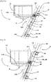
- the vehicle 1 is in the normal transit phase on two sections of track V with different inclinations, respectively of 70° and 20° relative to the horizontal.
- the support 120 is in the high position on the slide 12 and the damper 13 is then at rest.
- the figure 2B and 3B correspond to the same vehicle 1 traveling on the same sections of track V as those of the figures 2A and 2B but in a sudden slowdown or emergency stop situation.
- the support 120 due to the inertia of the vehicle 1, is driven downwards on the slide 12, but the damper 13 partially absorbs its kinetic energy by heat dissipation and then slows down the movement of the support 120 and therefore of the cabin 11. The stopping of the cabin 11 then takes place gradually.
- a hydraulic circuit 200 for controlling the hydraulic damper 13 which comprises a variable-volume chamber 201 secured to the carriage 10 and in which slides a piston 202 secured to the support 120 of the cabin 11.
- the variable-volume chamber 201 is connected to a tank 203 via a damping control valve 204 and a pressure drop 205.
- a filling control valve 206 makes it possible to connect the variable volume chamber 201 to a pump 207.
- the damping control valve 204 isolates the variable volume chamber 201, and the fill control valve 206, if present, links the damping control valve to the pressure drop 205.
- a circuit 208 controlled by an accelerometer 209 positioned on the carriage 10, causes the change of state of the damping control valve 204 in the event of a deceleration threshold of the carriage 10 being exceeded.
- a manual control 210 allows, when stopped, to activate the pump 207 and the filling control valve 206 to fill the variable-volume chamber 201 and bring the mobile support 120 of the cabin 11 back to the operational position.
- the device of the figure 5 is only one of the various solutions envisaged for locking the cabin support 120 relative to the carriage 10 in position in the operational position in the absence of sudden deceleration.
- the damping control valve 204 can be directly controlled by the hydraulic pressure in the variable-volume chamber 201, or more generally by a mechanical or hydraulic signal representative of an overrun of a force threshold between the variable volume chamber 201 and piston 202.
- a mechanical lock 304 rather than a hydraulic one, as illustrated in the figure 6 .
- a lock 404 placed directly between the cabin support 120 and the carriage 10, as illustrated in the figure 7 .
- the triggering of the locking will be controlled according to a triggering condition relating to the need for damping.
- This triggering condition may be determined according to one or more sensors, in particular speed, vertical or horizontal acceleration, inclination, or simply a malfunction alert, or by more specific sensors, for example a sensor cable break or an obstacle sensor.
- Also falling within the scope of the sensors envisaged are mechanisms performing interlocking between the lock 204, 304, 404 and an emergency brake, parachute brake or track brake or a speed limiter.
- Maintaining the attitude of the cabin 11 can be ensured by any appropriate means, and in particular by purely mechanical passive means or motorized active means, controlled by a signal representative, for example, of the horizontality of the cabin.
- Such a variant would be particularly suitable for an implementation of the invention in an attraction installation in which the trim of the cabin is deliberately modified during the journey.
Description
La présente invention concerne le domaine du transport de passagers et, plus particulièrement, un véhicule équipant une installation de transport et qui est déplacé de façon guidée, par glissement ou roulement, sur une voie d'inclinaison uniforme ou variable en étant mû par un ou plusieurs câbles.The present invention relates to the field of passenger transport and, more particularly, to a vehicle fitted to a transport installation and which is moved in a guided manner, by sliding or rolling, on a path of uniform or variable inclination while being moved by one or several cables.
Une telle installation de transport est, par exemple une installation de funiculaire roulant sur voie ferrée, une installation équivalente roulant sur voie non ferrée avec des véhicules sur pneus, ou bien encore une installation d'ascenseur vertical ou incliné.Such a transport installation is, for example, a funicular installation running on a railway, an equivalent installation running on a non-railway with vehicles on tires, or even a vertical or inclined lift installation.
L'invention se rapporte plus précisément à l'amortissement de la cinétique du véhicule lors d'une décélération survenant, notamment, lors d'un freinage brusque dans des circonstances exceptionnelles ou en situation d'urgence, par exemple, en cas de dysfonctionnement majeur du dispositif d'entraînement du véhicule, ou bien, en cas de survitesse ou de chute du véhicule à la suite d'une rupture de l'un ou de plusieurs des câbles de traction.The invention relates more specifically to the damping of the kinetics of the vehicle during deceleration occurring, in particular, during sudden braking in exceptional circumstances or in an emergency situation, for example, in the event of a major malfunction. of the vehicle drive device, or else, in the event of the vehicle overspeeding or falling following a break in one or more of the traction cables.
Ainsi, le document
Le document
Par ailleurs, les moyens d'amortissement décrits dans ce document sont destinés à des installations de transport dont les voies sont certes inclinées mais dont la pente est globalement constante.Furthermore, the damping means described in this document are intended for transport installations whose tracks are admittedly inclined but whose slope is generally constant.
Or, dans les installations dont les voies présentent une inclinaison variable, alors que l'assiette de la cabine doit rester horizontale sur tout le trajet, il est nécessaire de garantir aussi qu'en cas de freinage d'urgence ou d'arrêt brutal, son amortissement soit progressif, fiable et efficace, et reste dans des fourchettes de décélération prescrites réglementairement, tant pour l'accélération horizontale que pour l'accélération verticale, et ceci quelle que soit la position sur la voie.However, in installations where the tracks have a variable inclination, while the attitude of the cabin must remain horizontal throughout the journey, it is also necessary to guarantee that in the event of emergency braking or sudden stopping, its damping is progressive, reliable and effective, and remains within the deceleration ranges prescribed by law, both for horizontal acceleration and for vertical acceleration, and this regardless of the position on the track.
Dans ce contexte, l'invention a pour but de proposer une solution technique permettant de gérer les contraintes mécaniques et cinématiques résultant d'un tel cahier des charges.In this context, the aim of the invention is to propose a technical solution making it possible to manage the mechanical and kinematic constraints resulting from such specifications.
Ainsi, l'invention vise à intégrer à une installation de transports comportant un véhicule circulant sur une voie inclinée et tracté par un ou plusieurs câbles, par exemple, une installation d'ascenseur incliné ou de funiculaire, des moyens d'absorption d'énergie permettant de décélérer progressivement la cabine dans divers cas de freinage d'urgence initiés, par exemple, en freinant le ou les câbles de traction, ou en activant un frein parachute ou bien encore, à l'arrivée du véhicule en butée contre un tampon de l'installation ou contre un obstacle rencontré sur la voie.Thus, the invention aims to integrate into a transport installation comprising a vehicle traveling on an inclined track and towed by one or more cables, for example, an inclined elevator or funicular installation, means of energy absorption making it possible to gradually decelerate the cabin in various cases of emergency braking initiated, for example, by braking the traction cable or cables, or by activating a parachute brake or even, when the vehicle arrives in abutment against a buffer of the installation or against an obstacle encountered on the track.
L'invention vise subsidiairement à permettre l'intégration de tels moyens d'absorption d'énergie à une installation dont l'inclinaison n'est pas constante. Ce but est atteint selon l'invention au moyen d'un véhicule pour le transport de personnes sur une voie inclinée d'une installation de transport par câble, ledit véhicule comprenant un chariot apte à rouler sur la voie en étant tracté par un câble de traction de l'installation de transport, un support de cabine porté par le chariot, un dispositif de freinage embarqué et un amortisseur lié au dispositif de freinage embarqué et au support de la cabine et apte à transformer de l'énergie cinétique du support de cabine en chaleur lorsque le support de cabine se déplace par rapport au dispositif de freinage embarqué suivant une trajectoire d'amortissement dans un sens d'amortissement, caractérisé en ce que le dispositif de freinage embarqué est solidaire du chariot et le véhicule comporte en outre une liaison glissière entre le support de cabine et le chariot pour guider un mouvement du support de cabine par rapport au chariot suivant la trajectoire d'amortissement.The invention also aims to allow the integration of such energy absorption means in an installation whose inclination is not constant. This object is achieved according to the invention by means of a vehicle for transporting people on an inclined track of a cable transport installation, said vehicle comprising a carriage capable of rolling on the track while being towed by a cable traction of the transport installation, a cabin support carried by the trolley, an on-board braking device and a shock absorber connected to the on-board braking device and to the support of the cabin and capable of transforming kinetic energy from the cabin support in heat when the cabin support moves relative to the on-board braking device along a damping path in a damping direction, characterized in that the on-board braking device is integral with the truck and the vehicle further comprises a connection slide between the cabin support and the carriage to guide a movement of the cabin support relative to the carriage along the damping path.
Selon une caractéristique avantageuse, la trajectoire d'amortissement est rectiligne.According to an advantageous characteristic, the damping trajectory is rectilinear.
Selon un mode de réalisation préférentiel de l'invention, le chariot est muni d'au moins un train de roues pour rouler sur la voie, le ou les trains de roues définissant un plan de roulement, la trajectoire d'amortissement étant de préférence parallèle au plan de roulement.According to a preferred embodiment of the invention, the carriage is provided with at least one set of wheels to run on the track, the set of wheels defining a rolling plane, the damping path preferably being parallel on the rolling plane.
Selon une autre caractéristique, le chariot est pourvu d'une interface de liaison au câble de traction.According to another characteristic, the carriage is provided with an interface for connecting to the traction cable.
Selon une variante optionnelle de réalisation, le véhicule comporte en outre une cabine et une liaison pivot entre la cabine le support de cabine.According to an optional variant embodiment, the vehicle further comprises a cabin and a pivot connection between the cabin and the cabin support.
De préférence, cette liaison pivot est montée sous le plancher de la cabine.Preferably, this pivot link is mounted under the cabin floor.
Selon encore d'autres caractéristiques optionnelles, le véhicule comprend un dispositif de maintien d'assiette de la cabine, comportant de préférence au moins un jeu d'un ou plusieurs galets rotatifs destinés à coopérer avec au moins un rail auxiliaire de l'installation pour assurer le guidage et la correction d'assiette de la cabine.According to yet other optional characteristics, the vehicle comprises a device for maintaining the attitude of the cabin, preferably comprising at least one set of one or more rotating rollers intended to cooperate with at least one auxiliary rail of the installation for provide guidance and cabin attitude correction.
Selon une autre variante de réalisation, le chariot est muni d'un tampon destiné à venir, en cas d'urgence, en contact ultime avec un butoir à une extrémité inférieure de la voie.According to another alternative embodiment, the carriage is provided with a buffer intended to come, in the event of an emergency, into ultimate contact with a stopper at a lower end of the track.
L'amortisseur peut être de tout type permettant une dissipation d'énergie, notamment par frottement solide, déformation plastique d'un matériau, ou par des moyens électromagnétiques ou hydraulique. On préférera naturellement des moyens de dissipation d'énergie à usage multiple, pouvant, après un arrêt d'urgence ayant provoqué leur déclenchement, être réamorcés en ramenant le support de cabine en position opérationnelle. Selon un mode de réalisation particulièrement avantageux, l'amortisseur est un vérin hydraulique à longue course, ayant une course supérieure à 1m, et de préférence supérieure à 1,8 m. Naturellement, cette course pourra varier considérablement suivant les caractéristiques de l'installation, notamment en termes de vitesse et d'inclinaison, ainsi qu'en termes de prescriptions réglementaires, suivant par exemple qu'il s'agisse d'une installation d'ascenseur incliné, d'un funiculaire ou d'une installation d'attraction.The damper can be of any type allowing energy dissipation, in particular by solid friction, plastic deformation of a material, or by electromagnetic or hydraulic means. Naturally, multiple-use energy dissipation means will be preferred, which can, after an emergency stop that caused them to be triggered, be restarted by bringing the car support back into the operational position. According to a particularly advantageous embodiment, the damper is a long-stroke hydraulic cylinder, having a stroke greater than 1 m, and preferably greater than 1.8 m. Naturally, this stroke may vary considerably depending on the characteristics of the installation, in particular in terms of speed and inclination, as well as in terms of regulatory requirements, depending for example on whether it is a lift installation inclined, a funicular or an attraction installation.
Selon d'autres variantes particulières, le dispositif de freinage embarqué sur le chariot comprend un frein parachute ou un frein de voie.According to other particular variants, the braking device on board the trolley comprises a parachute brake or a track brake.
Suivant un mode de réalisation, le véhicule comporte un dispositif de verrouillage pour verrouiller l'amortisseur ou pour verrouiller le support de cabine en position par rapport au chariot tant qu'une condition de déclenchement n'est pas remplie, et pour libérer l'amortisseur ou le support de cabine lorsque la condition de déclenchement est remplie. On s'assure ainsi que l'amortisseur ne soit actif qu'en cas de besoin, et ne vienne pas perturber le fonctionnement normal de l'installation, par exemple dans des phases d'embarquement ou de débarquement, ou de déplacement en deçà des limites d'accélération prescrites.According to one embodiment, the vehicle comprises a locking device for locking the shock absorber or for locking the cabin support in position relative to the carriage as long as a triggering condition is not fulfilled, and for releasing the shock absorber or the car support when the trigger condition is met. This ensures that the shock absorber is only active when necessary, and does not interfere with the normal operation of the installation, for example in phases of embarkation or disembarkation, or movement below the prescribed acceleration limits.
La condition de déclenchement pourra être déterminée en fonction d'un ou plusieurs capteurs, notamment de vitesse, d'accélération verticale ou horizontale, ou d'inclinaison, ou simplement d'alerte de dysfonctionnement. La condition de déclenchement pourra être un dépassement de seuil pour un capteur, ou être une condition plus complexe, par exemple fonction de deux paramètres tels que la vitesse ou l'accélération et l'inclinaison. La condition de déclenchement pourra également être déterminée par un interverrouillage entre le dispositif de verrouillage et un mécanisme de freinage embarqué sur le véhicule, notamment un frein d'urgence, frein parachute ou frein de voie ou un limiteur de vitesse ou entre le dispositif de verrouillage et un détecteur de collision (par exemple un câble de détection tendu à l'extrémité basse du chariot). Le capteur peut également être intégré au verrou, en prévoyant qu'un effort dépassant un seuil donné sur le verrou entraîne un changement d'état du verrou, de préférence de manière réversible.The triggering condition may be determined as a function of one or more sensors, in particular speed, vertical or horizontal acceleration, or inclination, or simply a malfunction alert. The triggering condition may be a threshold overrun for a sensor, or be a more complex condition, for example a function of two parameters such as the speed or the acceleration and the inclination. The triggering condition may also be determined by interlocking between the locking device and a braking mechanism on board the vehicle, in particular an emergency brake, parachute brake or track brake or a speed limiter or between the locking device and a collision detector (for example a detection cable stretched at the lower end of the carriage). The sensor can also be integrated into the lock, by providing that a force exceeding a given threshold on the lock causes a change of state of the lock, preferably reversibly.
Le capteur peut également être intégré à un bouton poussoir de déclenchement ou à toute commande de déclenchement du dispositif de freinage d'urgence embarqué.The sensor can also be integrated into a release push button or any release control of the on-board emergency braking device.
Le dispositif de verrouillage peut comporter un verrou disposé directement entre le chariot et le support de cabine. Alternativement ou de façon additionnelle, le dispositif de verrouillage peut comporter un verrou de verrouillage en position d'un organe mobile de l'amortisseur par rapport à un corps de l'amortisseur, l'un des deux éléments d'amortisseur constitués par l'organe mobile de l'amortisseur et le corps de l'amortisseur étant fixé au chariot et l'autre des deux éléments d'amortisseur étant fixé au support de cabine.The locking device may include a lock disposed directly between the carriage and the cabin support. Alternatively or additionally, the locking device may comprise a locking bolt in position of a movable member of the shock absorber relative to a body of the shock absorber, one of the two shock absorber elements constituted by the movable member of the shock absorber and the body of the shock absorber being fixed to the carriage and the other of the two shock absorber elements being fixed to the cabin support.
De préférence est prévu un dispositif de réamorçage de l'amortisseur apte à déplacer le support de cabine par rapport au chariot dans la direction opposée à la direction d'amortissement jusqu'à la position opérationnelle. Ce dispositif présente de préférence des moyens moteurs, qui peuvent ou non indépendants de l'amortisseur. Il peut s'agir par exemple d'un moteur électrique agissant par l'intermédiaire d'une chaîne cinématique de transmission mécanique entre le chariot et le support de cabine. Il peut également s'agir d'un dispositif agissant sur l'amortisseur lui-même. Par exemple, dans le cas où l'amortisseur comporte un vérin hydraulique, il est possible d'alimenter la chambre hydraulique du vérin avec une pompe.Preferably, there is provided a device for repriming the shock absorber capable of moving the cabin support relative to the carriage in the direction opposite to the direction of damping up to the operational position. This device preferably has motor means, which may or may not be independent of the shock absorber. It may be for example an electric motor acting via a kinematic chain of mechanical transmission between the carriage and the cabin support. It can also be a device acting on the damper itself. By example, in the case where the shock absorber comprises a hydraulic jack, it is possible to supply the hydraulic chamber of the jack with a pump.
Un autre objet de l'invention est une installation de transport de personnes comprenant une station inférieure, une station supérieure, une voie inclinée reliant la station inférieure et la station supérieure, au moins un câble de traction, au moins un dispositif stationnaire d'entraînement du câble de traction, et au moins un véhicule apte à rouler sur la voie inclinée et en étant tracté par le câble de traction, caractérisée en ce que le véhicule est un véhicule de transport présentant les caractéristiques décrites ci-dessus. Par station inférieure et station supérieure, on désigne ici deux stations situées à des altitudes différentes, qu'il s'agisse de stations de fin de parcours ou de stations intermédiaires.Another object of the invention is a passenger transport installation comprising a lower station, an upper station, an inclined track connecting the lower station and the upper station, at least one traction cable, at least one stationary training device of the traction cable, and at least one vehicle able to run on the inclined track and being towed by the traction cable, characterized in that the vehicle is a transport vehicle having the characteristics described above. By lower station and upper station, we designate here two stations located at different altitudes, whether they are end of route stations or intermediate stations.
Selon une variante de réalisation de cette installation, le véhicule de transport est équipé d'un frein parachute ou frein de voie et est apte à coopérer avec un rail de freinage stationnaire de l'installation de transport. Ce rail de freinage peut être notamment un rail présentant une surface de friction pour un frein à friction du véhicule, ou un rail à crémaillère dans lequel vient s'insérer un doigt ou un crochet escamotable de blocage, solidaire du chariot.According to a variant embodiment of this installation, the transport vehicle is equipped with a parachute brake or track brake and is capable of cooperating with a stationary braking rail of the transport installation. This braking rail may in particular be a rail having a friction surface for a friction brake of the vehicle, or a rack rail into which is inserted a finger or a retractable locking hook, integral with the carriage.
Selon une autre variante, une extrémité inférieure de la voie est pourvue d'un butoir apte à venir, en cas d'urgence, au contact d'un tampon porté par le chariot du véhicule de transport.According to another variant, a lower end of the track is provided with a stopper capable of coming, in the event of an emergency, into contact with a buffer carried by the carriage of the transport vehicle.
Selon encore une autre variante, la voie présente une inclinaison non constante. Le cas échéant, le véhicule peut dans cette hypothèse comporter une cabine et une liaison pivot montée sous le plancher de la cabine entre la cabine et le support de cabine et un dispositif de maintien d'assiette de la cabine, comportant de préférence au moins un jeu d'un ou plusieurs galets rotatifs destinés à coopérer avec au moins un rail auxiliaire de l'installation pour assurer le guidage et la correction d'assiette de la cabine.According to yet another variant, the track has a non-constant inclination. If necessary, the vehicle can in this case comprise a cabin and a pivot connection mounted under the floor of the cabin between the cabin and the cabin support and a device for maintaining the attitude of the cabin, preferably comprising at least one set of one or more rotating rollers intended to cooperate with at least one auxiliary rail of the installation to ensure the guidance and the correction of the attitude of the cabin.
De préférence, l'installation comprend au moins un rail de maintien d'assiette avec lequel coopère un dispositif de maintien d'assiette de la cabine, comportant au moins un jeu d'un ou plusieurs galets rotatifs destinés à coopérer avec le rail de maintien d'assiette de l'installation.Preferably, the installation comprises at least one attitude maintaining rail with which a cabin attitude maintaining device cooperates, comprising at least one set of one or more rotating rollers intended to cooperate with the trim holding rail of the installation.
Selon une autre variante spécifique de l'installation, le dispositif stationnaire d'entraînement du câble comprend un système de freinage du câble.According to another specific variant of the installation, the stationary cable drive device comprises a cable braking system.
Le véhicule de l'invention assure, à la fois, un support équilibré et stable des cabines sur la voie et une capacité d'amortissement performante, en cas de freinage ou d'arrêt brusque, qui assure une décélération progressive et optimale.The vehicle of the invention provides both balanced and stable support for the cabins on the track and high-performance damping capacity, in the event of braking or sudden stopping, which ensures progressive and optimal deceleration.
L'installation de l'invention permet d'assurer un transport de passagers sur des trajets et des trajectoires ascendantes de profils et de géométries complexes et, en particulier, sur des voies d'inclinaison uniforme ou variable telles que voies paraboliques, tout en préservant le confort des passagers et en garantissant leur sécurité en toutes circonstances.The installation of the invention makes it possible to transport passengers on journeys and ascending trajectories of complex profiles and geometries and, in particular, on tracks of uniform or variable inclination such as parabolic tracks, while preserving passenger comfort and guaranteeing their safety in all circumstances.
D'autres caractéristiques et avantages de l'invention ressortiront à la lecture de la description qui va suivre, en référence à la figure annexée et détaillée ci-après.
- [
Fig. 1 ] est une vue d'ensemble d'une installation de transport comprenant une voie de pente variable sur laquelle se déplace un véhicule selon l'invention. - [
Fig. 2A ] est une vue de côté d'un mode de réalisation d'un véhicule selon l'invention dans une position correspondant à un tronçon de pente minimale de la voie inclinée et avant amortissement. - [
Fig. 2B ] est une vue de côté du véhicule de lafigure 2A dans la même position mais après amortissement. - [
Fig. 3A ] est une vue de côté d'un mode de réalisation d'un véhicule selon l'invention dans une position correspondant à un tronçon de pente maximale de la voie inclinée et avant amortissement. - [
Fig. 3B ] est une vue de côté du véhicule de lafigure 3A dans la même position mais après amortissement. - [
Fig. 4 ] est une vue de face du véhicule desfigures 2A et3A . - [
Fig. 5 ] est une vue schématique d'un circuit hydraulique de commande d'amortissement du véhicule des figures précédentes, intégrant un dispositif de verrouillage hydraulique de l'amortissement du véhicule. - [
Fig. 6 ] est une vue schématique d'un autre mode de réalisation d'un dispositif de verrouillage de l'amortissement du véhicule. - [
Fig. 7 ] est une vue schématique d'un troisième mode de réalisation d'un dispositif de verrouillage de l'amortissement du véhicule.
- [
Fig. 1 ] is an overall view of a transport installation comprising a track of variable slope on which a vehicle according to the invention moves. - [
Fig. 2A ] is a side view of an embodiment of a vehicle according to the invention in a position corresponding to a section of minimum slope of the inclined track and before damping. - [
Fig. 2B ] is a side view of the vehicle from thefigure 2A in the same position but after amortization. - [
Fig. 3A ] is a side view of an embodiment of a vehicle according to the invention in a position corresponding to a section of maximum slope of the inclined track and before damping. - [
Fig. 3B ] is a side view of the vehicle from theFigure 3A in the same position but after amortization. - [
Fig. 4 ] is a front view of the vehicle fromfigure 2A and3A . - [
Fig. 5 ] is a schematic view of a hydraulic damping control circuit of the vehicle of the preceding figures, incorporating a hydraulic locking device for the damping of the vehicle. - [
Fig. 6 ] is a schematic view of another embodiment of a vehicle damping locking device. - [
Fig. 7 ] is a schematic view of a third embodiment of a vehicle damping locking device.
Pour plus de clarté, les éléments identiques ou similaires sont repérés par des signes de référence identiques dans le texte et sur la figure.For greater clarity, identical or similar elements are identified by identical reference signs in the text and in the figure.
Naturellement, les modes de mise en œuvre de l'invention, illustrés par les figures annexées et décrits ci-après, ne sont donnés qu'à titre d'exemples non limitatifs. Il est explicitement prévu que l'on puisse proposer et combiner entre eux différents modes pour en proposer d'autres.Naturally, the embodiments of the invention, illustrated by the appended figures and described below, are given only by way of non-limiting examples. It is explicitly provided that it is possible to propose and combine different modes to propose others.
Le véhicule 1 objet de l'invention est destiné à assurer le transport de passagers dans une installation de transport T qui est, dans ce mode de réalisation, une installation d'ascenseur d'inclinaison uniforme ou variable, mais pourrait également être un funiculaire, voire une installation d'attraction.The
Dans le mode de réalisation illustré par la
Dans ce mode de réalisation et comme illustré, notamment, par les
Le véhicule 1 comprend, un chariot 10 apte à rouler sur la voie V en étant tracté par au moins un câble de traction C1 de l'installation de transport T, une cabine 11 et un support 120 de la cabine 11 porté par le chariot 10. A cet effet, le chariot 10 est pourvu d'une interface de liaison au câble de traction C1. Le véhicule 1 comporte, en outre, une liaison pivot 12 entre la cabine 11 et le support 120 de la cabine 11. Cette liaison pivot 12 est montée sous le plancher de la cabine 11, comme illustré, notamment, par les
Le véhicule 1 présente une structure symétrique par rapport à son plan vertical médian de sorte que les moyens décrits ci-après se trouvent de façon dupliquée, de part et d'autre du véhicule et de la voie, comme illustré par la
Le cas échéant, le véhicule 1 comprendra plusieurs cabines attelées ou solidaires d'un support commun. Le câble C1 est entraîné de manière traditionnelle par au moins un dispositif stationnaire d'entraînement tel qu'un moteur (non représenté).If necessary, the
Le véhicule 1 comprend, en outre, un dispositif de freinage embarqué 14 et un amortisseur 13 lié au dispositif de freinage embarqué et au support 120 de la cabine 11, comme illustré, notamment, par les
L'amortisseur 13 est ici un vérin hydraulique à longue course, ayant une course supérieure à 1m et, de préférence, supérieure à 1,8 m. Les autres paramètres de cet amortisseur seront déterminés en fonction de divers paramètres et, notamment, de la masse du véhicule 1 (avec la charge de ses passagers), de son inertie et des vitesses de consigne.The
L'installation de transport T est également équipée d'un système de freinage fixe (non représenté) qui complète le dispositif de freinage embarqué sur le véhicule 1 et qui est solidaire de son infrastructure et couplé au dispositif d'entraînement du câble C1 de traction. Les moyens de freinage, respectivement fixe et embarqué 14, sont, par exemple, conformes à ceux décrits et illustrés dans la demande de brevet
Ainsi, le système de freinage fixe et intégré à l'installation T est constitué, par exemple, de deux crémaillères parallèles (non représentées) s'étendant sur toute la longueur de la voie V, chacune à proximité de l'un des deux rails R1, R2 de la voie tandis que le dispositif de freinage 14 embarqué sur le véhicule 1 est constitué d'un frein parachute (visible notamment sur les
Selon un aspect spécifique de l'invention, le dispositif de freinage embarqué 14 est solidaire du chariot 10 et le véhicule 1 comporte en outre une liaison glissière 12 entre le support 120 de la cabine 11 et le chariot 10 pour guider un mouvement coulissant du support 120 de cabine par rapport au chariot 10 suivant la trajectoire d'amortissement. Dans le mode de réalisation de l'invention illustré par les figures, la trajectoire d'amortissement est rectiligne et la liaison glissière 12 s'étend parallèlement à la voie V. According to a specific aspect of the invention, the on-
Le chariot 10 est muni d'au moins un train de roues la, 1b pour rouler sur la voie V, le ou les trains de roues définissant un plan de roulement et la trajectoire d'amortissement étant, de préférence, parallèle à ce plan de roulement.The
Le véhicule de l'invention est équipé d'un dispositif de maintien d'assiette de la cabine 11. Ce dispositif comporte, de préférence, au moins un jeu d'un ou plusieurs galets rotatifs 111destinés à coopérer avec au moins un rail auxiliaire C2 de l'installation pour assurer le guidage et la correction d'assiette de la cabine 11. Ces galets 111 sont montés dans la partie basse de la structure de la cabine 11, du côté en regard de la voie V. The vehicle of the invention is equipped with a device for maintaining the attitude of the
Comme illustré par la
Le chariot 10 est muni, en partie basse, d'un tampon 101 destiné à venir, en fin de course d'urgence, en contact ultime avec le butoir B situé à l'extrémité inférieure de la voie V. Dans le mode de réalisation illustré par les figures, le support 120 de cabine a ici un profil triangulaire dont le sommet est raccordé, via un axe X, à une potence 110 s'étendant sous le plancher de la cabine 11. La glissière 12 est, quant à elle, constituée, par exemple, d'une rainure réalisée à la base du support 120 qui est engagée de façon coulissante dans une nervure solidaire du chariot 10. La configuration inverse est toutefois possible sans sortir du cadre de l'invention.The
En cas de freinage d'urgence (par ouverture du frein parachute 14 du chariot 10 ou d'activation du système de freinage fixe de l'installation T) ou d'arrêt brusque du chariot 10 sur le butoir B, en particulier, en cas de dysfonctionnement majeur de l'installation ou de rupture de l'un des câbles, et du fait de l'énergie cinétique du véhicule 1, le support 120 de la cabine 11coulisse vers le bas dans la glissière 12. Ce coulissement est ralenti par l'amortisseur 13 qui absorbe l'énergie cinétique du véhicule 1 pour maîtriser sa décélération.In the event of emergency braking (by opening the
L'équilibre du véhicule 1 et, en particulier l'assiette de la cabine 11, est conservé, même en cas de freinage ou d'arrêt d'urgence du véhicule, grâce à la maîtrise de la décélération du support 120 par l'amortisseur 13 via la glissière 12, ce qui garantit le confort des passagers et leur sécurité.The balance of the
Sur les
Les
Sur la
Par défaut, la soupape de commande d'amortissement 204 isole la chambre à volume variable 201, et la soupape de commande de remplissage 206, si elle est présente, lie la soupape de commande d'amortissement à la perte de charge 205. Un circuit de commande 208, piloté par un accéléromètre 209 positionné sur le chariot 10, provoque le changement d'état de la soupape de commande d'amortissement 204 en cas de dépassement d'un seuil de décélération du chariot 10. Une commande manuelle 210 permet, à l'arrêt, d'activer la pompe 207 et la soupape de commande de remplissage 206 pour remplir la chambre à volume variable 201 et ramener le support mobile 120 de la cabine 11 dans la position opérationnelle.By default, the damping
On permet ainsi que l'amortisseur hydraulique 13 ne soit activé qu'en cas de nécessité. Le temps de d'activation, ne dépassant pas quelques millisecondes est suffisamment bref pour que le seuil d'accélération admissible dans la cabine 11 ne soit pas dépassé.This allows the
Le dispositif de la
On peut prévoir d'autres types de verrouillage entre la chambre 201 et le piston 202 de l'amortisseur 13, par exemple par l'intermédiaire d'un verrou mécanique 304 plutôt qu'hydraulique, comme illustré sur la
Naturellement, diverses modifications sont possibles.Naturally, various modifications are possible.
Le maintien de l'assiette de la cabine 11 peut être assuré par tout moyen approprié, et notamment par des moyens passifs purement mécaniques ou des moyens actifs motorisés, commandé par un signal représentatif, par exemple, de l'horizontalité de la cabine. Une telle variante serait notamment adaptée à une implantation de l'invention dans une installation d'attraction dans laquelle l'assiette de la cabine est volontairement modifiée au cours du trajet.Maintaining the attitude of the
Claims (15)
- Vehicle (1) for transporting people on a sloping track (V) of a cable transport facility, said vehicle comprising a carriage (10) suitable for traveling on the track (V) while being pulled by at least one pull cable (C1) of the transport facility, a cabin support (120) carried by the carriage (10), an on-board braking device (14), and a shock absorber (13) connected to the on-board braking device (14) and to the cabin support (120) and suitable for converting kinetic energy of the cabin support (120) into heat when the cabin support (120) moves relative to the on-board braking device (14) from an operational position along a shock absorption path in a shock absorption direction, characterized in that the on-board braking device (14) is rigidly connected to the carriage (10) and the vehicle further includes a sliding connection (12) between the cabin support (120) and the carriage (10) to guide a movement of the cabin support (120) relative to the carriage (10) along the shock absorption path.
- Vehicle according to claim 1, characterized in that the shock absorption path is rectilinear, and in that the carriage (10) is preferably provided with at least one set (1a, 1b) of wheels for traveling on the track (V), the set(s) (1a, 1b) of wheels defining a traveling plane, the shock absorption path preferably being parallel to the traveling plane.
- Vehicle according to either of the preceding claims, characterized in that the carriage is provided with a connection interface to the pull cable (C1).
- Vehicle according to any of the preceding claims, characterized in that the vehicle further includes a cabin (11) and a pivot connection (12) between the cabin (11) and the cabin support (120), the pivot connection preferably being mounted under the cabin floor (11).
- Vehicle according to claim 4, characterized in that it comprises a device for maintaining the position of the cabin, preferably including at least one set of one or more rotary rollers (111) intended to cooperate with at least one auxiliary rail (C2) of the facility in order to guide and correct the attitude of the cabin (11).
- Vehicle according to any of the preceding claims, characterized in that said carriage (10) is provided with a buffer (101) intended, in the event of an emergency, to come into ultimate contact with a stop (B) at a lower end of the track (V).
- Vehicle according to any of the preceding claims, characterized in that said shock absorber (13) is a long-stroke hydraulic cylinder, having a stroke greater than 1 m, and preferably greater than 1.8 m.
- Vehicle according to any of the preceding claims, characterized in that the braking device (14) on board said carriage (10) comprises a parachute brake or a track brake.
- Vehicle according to any of the preceding claims, characterized in that it includes a locking device (204) for locking the shock absorber (13) or for locking the cabin support (120) in an operational position relative to the carriage (10) as long as a trigger condition is not fulfilled, and for releasing the shock absorber (13) or the cabin support (120) when the trigger condition is fulfilled, the locking device preferably including a lock arranged directly between the carriage (10) and the cabin support (120), the locking device preferably including a lock (204) for locking a movable member (202) of the shock absorber (13) in position relative to a body (201) of the shock absorber (13), one of the two shock absorber elements consisting of the movable member (202) of the shock absorber (13), and the body (201) of the shock absorber (13) being fixed to the carriage (10) and the other of the two shock absorber elements (202, 201) being fixed to the cabin support (120).
- Vehicle according to any of the preceding claims, characterized in that it includes a resetting device (206, 207) for the shock absorber (13) that is suitable for moving the cabin support (120) relative to the carriage (10) in the opposite direction to the shock absorption direction as far as the operational position.
- Facility (T) for transporting people comprising a lower station (S1), an upper station (S2), a sloping track (V) connecting the lower station (S1) and the upper station (S2), at least one pull cable (C1), at least one stationary device for driving the pull cable, and at least one vehicle (1) which is suitable for traveling on the sloping track (V) while being pulled by the pull cable, characterized in that the vehicle is a transport vehicle (1) according to any of the preceding claims, the stationary drive device preferably comprising a braking system of the pull cable (C1).
- Facility according to claim 11, characterized in that the transport vehicle is designed according to claim 8, and the parachute brake or track brake (14) is suitable for cooperating with a stationary braking rail of the transport facility.
- Facility according to either claim 11 or claim 12, characterized in that the transport vehicle is designed at least according to claim 6, and in that a lower end of the track (V) is provided with a stop (B) which is suitable for coming into contact with the buffer (101) in order to ultimately stop the vehicle (1).
- Facility according to any of claims 11 to 13, characterized in that the vehicle is designed at least according to either claim 4 or claim 5 and the track has a non-constant slope.
- Facility according to claim 14, characterized in that the vehicle is designed according to claim 5, and the facility comprises at least one position-maintaining rail (C2) with which the set of one or more rotary rollers (111) cooperates.
Applications Claiming Priority (1)
| Application Number | Priority Date | Filing Date | Title |
|---|---|---|---|
| FR2000137A FR3105964B1 (en) | 2020-01-08 | 2020-01-08 | CUSHIONED VEHICLE FOR TRANSPORTING PASSENGERS ON A ROAD OF VARIABLE SLOPE AND INSTALLATION COMPRISING SUCH VEHICLE |
Publications (2)
| Publication Number | Publication Date |
|---|---|
| EP3848267A1 EP3848267A1 (en) | 2021-07-14 |
| EP3848267B1 true EP3848267B1 (en) | 2022-08-31 |
Family
ID=69903624
Family Applications (1)
| Application Number | Title | Priority Date | Filing Date |
|---|---|---|---|
| EP21150710.8A Active EP3848267B1 (en) | 2020-01-08 | 2021-01-08 | Vehicle fitted with shock absorbers for transporting passengers on a track with variable slope and facility comprising said vehicle |
Country Status (8)
| Country | Link |
|---|---|
| US (1) | US11713212B2 (en) |
| EP (1) | EP3848267B1 (en) |
| JP (1) | JP2021109650A (en) |
| KR (1) | KR20210089580A (en) |
| CN (1) | CN113173183A (en) |
| CA (1) | CA3103334A1 (en) |
| ES (1) | ES2930271T3 (en) |
| FR (1) | FR3105964B1 (en) |
Families Citing this family (1)
| Publication number | Priority date | Publication date | Assignee | Title |
|---|---|---|---|---|
| CN115303911B (en) * | 2022-08-24 | 2023-10-10 | 海标工程管理有限公司 | Building site dangerous point monitoring and processing device and method |
Family Cites Families (9)
| Publication number | Priority date | Publication date | Assignee | Title |
|---|---|---|---|---|
| FR2311698A1 (en) * | 1975-05-23 | 1976-12-17 | Creissels Denis Sa | INCLINED ELEVATOR |
| JPH10167626A (en) * | 1996-12-03 | 1998-06-23 | Mitsubishi Electric Corp | Oblique elevator car device |
| US6216826B1 (en) * | 1999-01-19 | 2001-04-17 | Michael John Botzet | Bank hoist braking apparatus |
| JP4582605B2 (en) * | 2000-09-12 | 2010-11-17 | 日本ケーブル株式会社 | Cable car vehicle brake system |
| GB0901342D0 (en) * | 2009-01-27 | 2009-03-11 | Godwin Michael | Safety device for a passenger transportation system |
| US9038780B2 (en) * | 2010-05-31 | 2015-05-26 | Geosen | Safety brake for incline elevators |
| KR101400806B1 (en) * | 2012-12-31 | 2014-05-29 | (주)새한엘리베이터 | Elevator |
| FR3012121B1 (en) | 2013-10-21 | 2017-12-08 | Baudin Chateauneuf | VEHICLE COMPRISING AN ELEVATOR, PARTICULARLY FOR RECEIVING PASSENGERS |
| FR3079223B1 (en) | 2018-03-22 | 2020-04-17 | Poma | EMERGENCY BRAKING SYSTEM FOR A TRANSPORTATION SYSTEM COMPRISING AT LEAST ONE VEHICLE GUIDED ON A VERTICAL OR INCLINED TRACK |
-
2020
- 2020-01-08 FR FR2000137A patent/FR3105964B1/en active Active
- 2020-12-21 CA CA3103334A patent/CA3103334A1/en active Pending
- 2020-12-23 JP JP2020213818A patent/JP2021109650A/en active Pending
- 2020-12-30 KR KR1020200188040A patent/KR20210089580A/en active Search and Examination
-
2021
- 2021-01-06 CN CN202110013841.6A patent/CN113173183A/en active Pending
- 2021-01-08 US US17/144,745 patent/US11713212B2/en active Active
- 2021-01-08 EP EP21150710.8A patent/EP3848267B1/en active Active
- 2021-01-08 ES ES21150710T patent/ES2930271T3/en active Active
Also Published As
| Publication number | Publication date |
|---|---|
| FR3105964A1 (en) | 2021-07-09 |
| KR20210089580A (en) | 2021-07-16 |
| US11713212B2 (en) | 2023-08-01 |
| US20210253398A1 (en) | 2021-08-19 |
| FR3105964B1 (en) | 2022-01-14 |
| CN113173183A (en) | 2021-07-27 |
| EP3848267A1 (en) | 2021-07-14 |
| JP2021109650A (en) | 2021-08-02 |
| ES2930271T3 (en) | 2022-12-09 |
| CA3103334A1 (en) | 2021-07-08 |
Similar Documents
| Publication | Publication Date | Title |
|---|---|---|
| EP0242242B1 (en) | Ski lift seat with automatic control of the seat protection devices | |
| EP3023332B1 (en) | Aircraft tractor | |
| EP1721827B1 (en) | Anti-crash method and system, undercarriage and aircraft | |
| FR2925348A1 (en) | LARGE WHEEL TYPE VERTICAL WHEEL-TYPE ATTRACTION APPARATUS WITH SUSPENDED CABINS | |
| EP2781424B1 (en) | Car for a rail vehicle including an access system | |
| EP3848267B1 (en) | Vehicle fitted with shock absorbers for transporting passengers on a track with variable slope and facility comprising said vehicle | |
| EP1351878B1 (en) | Emergency braking device for a vehicle towed or suspended by cables and vehicle equipped with such a device | |
| FR2810655A1 (en) | VARIABLE TRACTION MECHANISM FOR A ROTARY CONTROLLER OF OVERSPEED SAFETY DEVICE | |
| EP2780209B1 (en) | Mechanical lift vehicle | |
| EP0223706B1 (en) | Device for the automatic actuation of the sliding door of a guided vehicle | |
| WO1998015443A1 (en) | Method and device for controlling the displacement of a cabin along a cableway line and application to a system of public transport | |
| EP0227508B1 (en) | Funicular transport installation with a safety device for emergency braking for at least one of the transport vehicles | |
| EP1282579A1 (en) | Lift cage governor | |
| RU2813171C2 (en) | Vehicle with shock absorption for transporting passengers on path with variable incline and installation containing said vehicle | |
| FR3079223A1 (en) | EMERGENCY BRAKING SYSTEM FOR A TRANSPORT FACILITY COMPRISING AT LEAST ONE VEHICLE GUIDED ON A VERTICAL OR INCLINED TRACK | |
| FR2687356A1 (en) | TRANSPORTATION SYSTEM COMPRISING CABLE TRACKABLE VEHICLES AND METHOD OF CONTROLLING THE SAME. | |
| FR2937939A1 (en) | Double mono-cable installation for displacing e.g. open carrier for transporting freight, has rollers whose axles are movable such that rollers are moved away from pulley, while being opposed to support unit action, during passage of clamps | |
| FR3066745A1 (en) | RAILWAY VEHICLE COMPRISING AERODYNAMIC BRAKE DEVICE | |
| EP0573344A1 (en) | Transport system with rope tracted railway vehicles | |
| FR2506279A1 (en) | Safety brake for load carrying bogie - has winch operated carriage supplying building materials up ladder of spring and cable type | |
| FR2687357A1 (en) | TRANSPORTATION SYSTEM COMPRISING CABLE TRACKABLE VEHICLES PROVIDED WITH IMPROVED CLAMPS. | |
| EP1361110A1 (en) | Goods transportation vehicle with a lifting platform | |
| JP5737872B2 (en) | Engine tilting device for single rail conveyor | |
| FR3079194A1 (en) | DEVICE FOR DRIVING TENSION CABLES OF AT LEAST ONE VEHICLE ON AN INCLINED OR VERTICAL TRACK AND PASSENGER TRANSPORTATION EQUIPPED WITH SUCH A DEVICE | |
| FR2689846A1 (en) | Equipment for automatically disconnecting chair-lift at stations - uses control rails which first open and then close jaws normally gripping driving cable |
Legal Events
| Date | Code | Title | Description |
|---|---|---|---|
| PUAI | Public reference made under article 153(3) epc to a published international application that has entered the european phase |
Free format text: ORIGINAL CODE: 0009012 |
|
| STAA | Information on the status of an ep patent application or granted ep patent |
Free format text: STATUS: THE APPLICATION HAS BEEN PUBLISHED |
|
| AK | Designated contracting states |
Kind code of ref document: A1 Designated state(s): AL AT BE BG CH CY CZ DE DK EE ES FI FR GB GR HR HU IE IS IT LI LT LU LV MC MK MT NL NO PL PT RO RS SE SI SK SM TR |
|
| STAA | Information on the status of an ep patent application or granted ep patent |
Free format text: STATUS: REQUEST FOR EXAMINATION WAS MADE |
|
| 17P | Request for examination filed |
Effective date: 20210928 |
|
| RBV | Designated contracting states (corrected) |
Designated state(s): AL AT BE BG CH CY CZ DE DK EE ES FI FR GB GR HR HU IE IS IT LI LT LU LV MC MK MT NL NO PL PT RO RS SE SI SK SM TR |
|
| REG | Reference to a national code |
Ref country code: HK Ref legal event code: DE Ref document number: 40053571 Country of ref document: HK |
|
| GRAP | Despatch of communication of intention to grant a patent |
Free format text: ORIGINAL CODE: EPIDOSNIGR1 |
|
| STAA | Information on the status of an ep patent application or granted ep patent |
Free format text: STATUS: GRANT OF PATENT IS INTENDED |
|
| INTG | Intention to grant announced |
Effective date: 20220328 |
|
| GRAS | Grant fee paid |
Free format text: ORIGINAL CODE: EPIDOSNIGR3 |
|
| GRAA | (expected) grant |
Free format text: ORIGINAL CODE: 0009210 |
|
| STAA | Information on the status of an ep patent application or granted ep patent |
Free format text: STATUS: THE PATENT HAS BEEN GRANTED |
|
| AK | Designated contracting states |
Kind code of ref document: B1 Designated state(s): AL AT BE BG CH CY CZ DE DK EE ES FI FR GB GR HR HU IE IS IT LI LT LU LV MC MK MT NL NO PL PT RO RS SE SI SK SM TR |
|
| REG | Reference to a national code |
Ref country code: CH Ref legal event code: EP Ref country code: GB Ref legal event code: FG4D Free format text: NOT ENGLISH |
|
| REG | Reference to a national code |
Ref country code: AT Ref legal event code: REF Ref document number: 1515093 Country of ref document: AT Kind code of ref document: T Effective date: 20220915 Ref country code: DE Ref legal event code: R096 Ref document number: 602021000347 Country of ref document: DE |
|
| REG | Reference to a national code |
Ref country code: IE Ref legal event code: FG4D Free format text: LANGUAGE OF EP DOCUMENT: FRENCH |
|
| REG | Reference to a national code |
Ref country code: SE Ref legal event code: TRGR |
|
| REG | Reference to a national code |
Ref country code: NO Ref legal event code: T2 Effective date: 20220831 |
|
| REG | Reference to a national code |
Ref country code: ES Ref legal event code: FG2A Ref document number: 2930271 Country of ref document: ES Kind code of ref document: T3 Effective date: 20221209 |
|
| REG | Reference to a national code |
Ref country code: LT Ref legal event code: MG9D |
|
| REG | Reference to a national code |
Ref country code: NL Ref legal event code: MP Effective date: 20220831 |
|
| PG25 | Lapsed in a contracting state [announced via postgrant information from national office to epo] |
Ref country code: RS Free format text: LAPSE BECAUSE OF FAILURE TO SUBMIT A TRANSLATION OF THE DESCRIPTION OR TO PAY THE FEE WITHIN THE PRESCRIBED TIME-LIMIT Effective date: 20220831 Ref country code: LV Free format text: LAPSE BECAUSE OF FAILURE TO SUBMIT A TRANSLATION OF THE DESCRIPTION OR TO PAY THE FEE WITHIN THE PRESCRIBED TIME-LIMIT Effective date: 20220831 Ref country code: LT Free format text: LAPSE BECAUSE OF FAILURE TO SUBMIT A TRANSLATION OF THE DESCRIPTION OR TO PAY THE FEE WITHIN THE PRESCRIBED TIME-LIMIT Effective date: 20220831 Ref country code: FI Free format text: LAPSE BECAUSE OF FAILURE TO SUBMIT A TRANSLATION OF THE DESCRIPTION OR TO PAY THE FEE WITHIN THE PRESCRIBED TIME-LIMIT Effective date: 20220831 |
|
| PG25 | Lapsed in a contracting state [announced via postgrant information from national office to epo] |
Ref country code: PL Free format text: LAPSE BECAUSE OF FAILURE TO SUBMIT A TRANSLATION OF THE DESCRIPTION OR TO PAY THE FEE WITHIN THE PRESCRIBED TIME-LIMIT Effective date: 20220831 Ref country code: IS Free format text: LAPSE BECAUSE OF FAILURE TO SUBMIT A TRANSLATION OF THE DESCRIPTION OR TO PAY THE FEE WITHIN THE PRESCRIBED TIME-LIMIT Effective date: 20221231 Ref country code: HR Free format text: LAPSE BECAUSE OF FAILURE TO SUBMIT A TRANSLATION OF THE DESCRIPTION OR TO PAY THE FEE WITHIN THE PRESCRIBED TIME-LIMIT Effective date: 20220831 Ref country code: GR Free format text: LAPSE BECAUSE OF FAILURE TO SUBMIT A TRANSLATION OF THE DESCRIPTION OR TO PAY THE FEE WITHIN THE PRESCRIBED TIME-LIMIT Effective date: 20221201 |
|
| PG25 | Lapsed in a contracting state [announced via postgrant information from national office to epo] |
Ref country code: SM Free format text: LAPSE BECAUSE OF FAILURE TO SUBMIT A TRANSLATION OF THE DESCRIPTION OR TO PAY THE FEE WITHIN THE PRESCRIBED TIME-LIMIT Effective date: 20220831 Ref country code: RO Free format text: LAPSE BECAUSE OF FAILURE TO SUBMIT A TRANSLATION OF THE DESCRIPTION OR TO PAY THE FEE WITHIN THE PRESCRIBED TIME-LIMIT Effective date: 20220831 Ref country code: PT Free format text: LAPSE BECAUSE OF FAILURE TO SUBMIT A TRANSLATION OF THE DESCRIPTION OR TO PAY THE FEE WITHIN THE PRESCRIBED TIME-LIMIT Effective date: 20230102 Ref country code: DK Free format text: LAPSE BECAUSE OF FAILURE TO SUBMIT A TRANSLATION OF THE DESCRIPTION OR TO PAY THE FEE WITHIN THE PRESCRIBED TIME-LIMIT Effective date: 20220831 Ref country code: CZ Free format text: LAPSE BECAUSE OF FAILURE TO SUBMIT A TRANSLATION OF THE DESCRIPTION OR TO PAY THE FEE WITHIN THE PRESCRIBED TIME-LIMIT Effective date: 20220831 |
|
| PGFP | Annual fee paid to national office [announced via postgrant information from national office to epo] |
Ref country code: NO Payment date: 20230120 Year of fee payment: 3 Ref country code: FR Payment date: 20230320 Year of fee payment: 3 Ref country code: ES Payment date: 20230216 Year of fee payment: 3 |
|
| PG25 | Lapsed in a contracting state [announced via postgrant information from national office to epo] |
Ref country code: SK Free format text: LAPSE BECAUSE OF FAILURE TO SUBMIT A TRANSLATION OF THE DESCRIPTION OR TO PAY THE FEE WITHIN THE PRESCRIBED TIME-LIMIT Effective date: 20220831 Ref country code: EE Free format text: LAPSE BECAUSE OF FAILURE TO SUBMIT A TRANSLATION OF THE DESCRIPTION OR TO PAY THE FEE WITHIN THE PRESCRIBED TIME-LIMIT Effective date: 20220831 |
|
| PGFP | Annual fee paid to national office [announced via postgrant information from national office to epo] |
Ref country code: SE Payment date: 20230123 Year of fee payment: 3 Ref country code: IT Payment date: 20230131 Year of fee payment: 3 |
|
| REG | Reference to a national code |
Ref country code: DE Ref legal event code: R097 Ref document number: 602021000347 Country of ref document: DE |
|
| PG25 | Lapsed in a contracting state [announced via postgrant information from national office to epo] |
Ref country code: NL Free format text: LAPSE BECAUSE OF FAILURE TO SUBMIT A TRANSLATION OF THE DESCRIPTION OR TO PAY THE FEE WITHIN THE PRESCRIBED TIME-LIMIT Effective date: 20220831 Ref country code: AL Free format text: LAPSE BECAUSE OF FAILURE TO SUBMIT A TRANSLATION OF THE DESCRIPTION OR TO PAY THE FEE WITHIN THE PRESCRIBED TIME-LIMIT Effective date: 20220831 |
|
| PLBE | No opposition filed within time limit |
Free format text: ORIGINAL CODE: 0009261 |
|
| STAA | Information on the status of an ep patent application or granted ep patent |
Free format text: STATUS: NO OPPOSITION FILED WITHIN TIME LIMIT |
|
| 26N | No opposition filed |
Effective date: 20230601 |
|
| PG25 | Lapsed in a contracting state [announced via postgrant information from national office to epo] |
Ref country code: SI Free format text: LAPSE BECAUSE OF FAILURE TO SUBMIT A TRANSLATION OF THE DESCRIPTION OR TO PAY THE FEE WITHIN THE PRESCRIBED TIME-LIMIT Effective date: 20220831 |
|
| PG25 | Lapsed in a contracting state [announced via postgrant information from national office to epo] |
Ref country code: LU Free format text: LAPSE BECAUSE OF NON-PAYMENT OF DUE FEES Effective date: 20230108 |
|
| REG | Reference to a national code |
Ref country code: BE Ref legal event code: MM Effective date: 20230131 |
|
| PG25 | Lapsed in a contracting state [announced via postgrant information from national office to epo] |
Ref country code: BE Free format text: LAPSE BECAUSE OF NON-PAYMENT OF DUE FEES Effective date: 20230131 |
|
| PGFP | Annual fee paid to national office [announced via postgrant information from national office to epo] |
Ref country code: DE Payment date: 20230630 Year of fee payment: 3 |
|
| PG25 | Lapsed in a contracting state [announced via postgrant information from national office to epo] |
Ref country code: IE Free format text: LAPSE BECAUSE OF NON-PAYMENT OF DUE FEES Effective date: 20230108 |
|
| REG | Reference to a national code |
Ref country code: AT Ref legal event code: UEP Ref document number: 1515093 Country of ref document: AT Kind code of ref document: T Effective date: 20220831 |
|
| PGFP | Annual fee paid to national office [announced via postgrant information from national office to epo] |
Ref country code: ES Payment date: 20240213 Year of fee payment: 4 |