EP0573344A1 - Transport system with rope tracted railway vehicles - Google Patents
Transport system with rope tracted railway vehicles Download PDFInfo
- Publication number
- EP0573344A1 EP0573344A1 EP93401385A EP93401385A EP0573344A1 EP 0573344 A1 EP0573344 A1 EP 0573344A1 EP 93401385 A EP93401385 A EP 93401385A EP 93401385 A EP93401385 A EP 93401385A EP 0573344 A1 EP0573344 A1 EP 0573344A1
- Authority
- EP
- European Patent Office
- Prior art keywords
- cable
- vehicle
- vehicles
- clamp
- speed
- Prior art date
- Legal status (The legal status is an assumption and is not a legal conclusion. Google has not performed a legal analysis and makes no representation as to the accuracy of the status listed.)
- Withdrawn
Links
Images


Classifications
-
- B—PERFORMING OPERATIONS; TRANSPORTING
- B61—RAILWAYS
- B61B—RAILWAY SYSTEMS; EQUIPMENT THEREFOR NOT OTHERWISE PROVIDED FOR
- B61B9/00—Tramway or funicular systems with rigid track and cable traction
-
- B—PERFORMING OPERATIONS; TRANSPORTING
- B61—RAILWAYS
- B61B—RAILWAY SYSTEMS; EQUIPMENT THEREFOR NOT OTHERWISE PROVIDED FOR
- B61B12/00—Component parts, details or accessories not provided for in groups B61B7/00 - B61B11/00
- B61B12/12—Cable grippers; Haulage clips
- B61B12/125—Cable grippers; Haulage clips for non aerial ropeways, e.g. on or under the ground
Definitions
- the present invention relates to the field of transport systems comprising vehicles traveling on rails and towed by a cable, between stations, by disengageable clamps.
- Transport systems of the aforementioned type have given rise to a very abundant literature and extensive research. They have a quality essential. Thanks to short intervals between vehicles (typically 15s to 40s), they practically eliminate the waiting of passengers.
- document US-A-3871303 proposes to provide each vehicle 20 with at least two clamps of the type shown in the appended FIG. 2, capable of engaging / disengaging respectively on the main drive cable 10 and one secondary drive cables.
- the clamps of the type shown in FIG. 2 are designed, as for cable cars, to ensure a clamping on the associated cable, with sufficient force to prevent any sliding of the vehicles 20 relative to the cable, at their maximum load.
- the clamp 50 represented in the appended FIG. 2 comprises two jaws 51, 52, articulated around an axis 54 on a frame 53.
- the jaws 51, 52 are urged to close on an associated cable 60, as shown in broken dashed lines in Figure 2, by a spring 55 schematically illustrated in this figure.
- each jaw 51, 52 is equipped with a roller 56, 57 able to roll on a cam on the ground 70, 71.
- the jaws 51, 52 are moved to the open position when the rollers 56, 57 roll on the cams 70, 71.
- Variants of clamps have also been proposed comprising a fixed jaw and a single movable jaw urged to close by a spring.
- the vehicle 20 is disengaged from the cable 60 in the open position of the jaws 51, 52. Conversely, the vehicle is engaged on the cable 60, without the possibility of sliding relative to the latter in the closed position of the jaws 51, 52.
- This condition can be fulfilled in a transport system with suspended gondolas insofar as these can absorb a speed difference with a drive cable when clutching this cable, by swinging in pendulum motion.
- progressive clutch are adapted to accept a relative displacement parallel to the cable, between the clamp and the cable at the time of its clutch on the cable, and achieve all or part of the acceleration and deceleration of the vehicle.
- these progressive clutch pliers have made it possible to overcome the constraint of speed synchronism when clutching vehicles and to eliminate the means of acceleration / deceleration at variable speed such as described for example in document US-A-3871303, replacing them with accelerator / decelerator assemblies driven at constant speed, as described for example in document FR-A-2453064.
- the applicant has himself carried out installations comprising accelerator / decelerator formed by bands driven at constant speed on which rest wheels carried by vehicles.
- accelerator / decelerator formed by bands driven at constant speed on which rest wheels carried by vehicles.
- the progressive clutch clamp has been improved, with two-stage tightening, described in document FR-A-2,591,548.
- the present invention now aims to provide a new transport system which is both as safe, more comfortable and simpler than the known prior transport systems.
- each vehicle comprises at least one clamp with progressive clutch with direct friction on an associated cable
- the accelerator / decelerator means are driven by variable speed means controlled to ensure passenger comfort during the vehicle acceleration / deceleration phases and limit the difference in speed between a vehicle and the associated cable when said progressive clutch clip is engaged thereon .
- the invention makes it possible to simplify the structure of the clamp and to improve passenger comfort by going back to the approach followed by those skilled in the art for ten years.
- the comfort of the passengers during the acceleration / deceleration phases of the vehicles and the speed synchronism are ensured by the means to variable speed, the progressive clutch pliers being provided only to guarantee the safety of the passengers in the event of a lack of speed synchronism, which very rarely occurs.
- the transport system of the present invention complies with the provisions shown in Figure 1 attached. However, it can include any number of terminal stations or intermediaries. Furthermore, it is not limited to straight tracks and can include curved track sections.
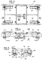
- the vehicles according to the present invention essentially consist of an upper chassis 100 designed to accommodate passengers and a lower chassis 200 which carries at least one structure of progressive clutch pliers and horizontal axis support wheels as well as vertical axis guide rollers in contact with rails.
- FIGS. 3 and 4 show four wheels 202, 204, 206 and 208 with a horizontal axis which rest on rails 300, 302.
- rollers 210, 212, 214, 216 of vertical axis which roll on the rail 300, respectively on either side thereof.
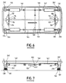
- the upper chassis 100 is suspended from the lower chassis 200 by four tie rods 248, 250 and shock absorbers 102, 104, 106 and 108 visible in FIGS. 6 and 7. Stops 110 and 112 limit the relative longitudinal displacement between the upper chassis 100 and the lower chassis 200. Similarly stops 114, 116, 118 and 120 limit the relative transverse movement between the upper chassis 100 and the lower chassis 200.
- the lower chassis 200 is provided with at least one progressive clutch pliers. More specifically, preferably, the lower chassis 200 is provided with two progressive clutch pliers 220 and 230 as shown in FIG. 5. These pliers 220 and 230 are accessible under the structure of the lower chassis 200 to cooperate respectively with a cable main drive 10 and a secondary drive cable 80 used to accelerate or decelerate vehicles 20.
- each clamp 220 and 230 comprises a fixed jaw 222, 232 and a movable jaw 224, 234 articulated on the fixed jaw around a horizontal axis.
- the movable jaw 224, 234 is biased towards a closed position in which the two jaws 222 and 224, respectively 232 and 234, clamp the cable 10, respectively 80, by control means generating a clamping force compatible with a relative displacement between the clamp and the cable when clutching the cable when there is a significant speed difference between the vehicle and the cable.
- each movable jaw 224, 234 can be urged to open, in a manner known per se, by a cam on the ground.
- each movable jaw 224, 234, comprises a roller 226, 236, capable of rolling on said cam.
- the progressive clutch pliers described in document FR-A-2475485 include braked rollers provided with internal friction lining.
- the clamps 220, 230 are directly friction on the cable, that is to say that they are provided with jaws which rub on the cables 10, 80 in the event of relative displacement of the clamp / cable.
- the longitudinal force exerted on the clamp is proportional to the transverse clamping force, the coefficient of proportionality being defined by the coefficient of friction between the jaws of the jaws and cable.
- the material of the jaws and their shape are provided to limit the wear of the cable and the tolerance of the coefficient of friction.
- the longitudinal force exerted on the clamp leads to an acceleration which depends on the mass of the vehicle.
- control means are advantageously adapted to generate a clamping force between the minimum corresponding to an acceleration of the order of 2m / s2 allowing, for example, to overcome a slope of 10%, a frontal wind equivalent to a slope of 8% and the friction forces of the bearings equivalent to a slope of 2%.
- the maximum allowable clamping force is defined by the maximum acceleration acceptable for passenger safety. This acceleration is typically less than 4m / s2, very advantageously of the order of 2.5m / s2.
- the clamps are preferably controlled for this purpose by a weighing system sensitive to the mass of the vehicle.
- rocker legs 130, 132, 134, 136 are each provided with an emergency stop pad 160, 162.
- Clamps 220, 230, with progressive clutch and direct friction on the cable can be used for tightening the secondary acceleration and deceleration cables and / or for tightening the main drive cable.
- the progressive clutch clamps in accordance with the present invention have a very simple and space-saving structure, as can be seen for example by examining FIG. 5.
- the present invention easily allows the implantation, under the lower chassis 200, of two clamps able to cooperate respectively with the main drive cable 10 and the secondary accelerator / decelerator cables 80.
- the cables 80 used to provide acceleration 40 or deceleration 30 are driven at variable speed.
- the cable ensuring acceleration is driven between a slow or even zero speed when a vehicle is engaged on this cable and a speed fast equal to the speed of the main drive cable, when the throttle cable is disengaged and the clutch on the main drive cable.
- the cable ensuring the deceleration is driven between a rapid speed equal to the speed of the main drive cable, when clutching the deceleration cable and disengaging the main drive cable and a slow or even zero speed.
- the accelerator and decelerator cables 80 In normal operation, the accelerator and decelerator cables 80 fully provide the required variations in vehicle speed 20. The clamps 220 and 230 consequently do not undergo any relative slippage relative to the associated cables. However, in the event of a fault resulting in a difference in speed when clutching a cable, the progressive clutch pliers in accordance with the present invention make it possible to limit the accelerations undergone by the vehicles to values compatible with the safety of the passengers carried. .
Abstract
Description
La présente invention concerne le domaine des systèmes de transport comprenant des véhicules roulant sur des rails et tractés par un câble, entre des stations, par des pinces débrayables.The present invention relates to the field of transport systems comprising vehicles traveling on rails and towed by a cable, between stations, by disengageable clamps.
Les premières utilisations de véhicules tractés par cable sont très anciennes, tant pour le transport de matières (dans les mines en particulier) que celui des passagers (funiculaire de Montmartre, "cable car" de San Francisco).The first uses of vehicles towed by cable are very old, as much for the transport of materials (in mines in particular) as that of the passengers (funicular of Montmartre, "cable car" of San Francisco).
Plus précisément, la présente invention s'applique aux systèmes de transport connus du type représenté sur la figure 1 annexée comprenant :
- au moins un câble principal d'entraînement 10 entraîné à vitesse rapide et continue (typiquement de l'ordre de 20km/h) entre des stations S1, S2,
- une pluralité de
véhicules 20 comportant des pinces aptes à embrayer/débrayer sur le câble principal d'entraînement 10, pour permettre le déplacement des véhicules entre les stations S1, S2, et - au niveau de chaque station S1, S2 :
- . à l'arrivée en station, des moyens aptes à commander les pinces à l'ouverture pour débrayer les
véhicules 20 du câble principal d'entraînement 10, et desmoyens 30 aptes à ralentir lesvéhicules 20 jusqu'à une vitesse lente (typiquement 1km/h) ou un arrêt pour permettre l'embarquement et/ou le débarquement des passagers, et - . au départ de la station, des
moyens 40 aptes à accélérer lesvéhicules 20 au moins sensiblement jusqu'à la vitesse du câble principal d'entraînement 10, et des moyens aptes à provoquer la fermeture des pinces pour commander l'embrayage desvéhicules 20 sur le câble principal d'entraînement 10.
- . à l'arrivée en station, des moyens aptes à commander les pinces à l'ouverture pour débrayer les
- at least one
main drive cable 10 driven at rapid and continuous speed (typically of the order of 20 km / h) between stations S1, S2, - a plurality of
vehicles 20 comprising clamps capable of engaging / disengaging on themain drive cable 10, to allow movement of the vehicles between the stations S1, S2, and - at each station S1, S2:
- . on arrival at the station, means capable of controlling the clamps when opening to disengage the
vehicles 20 from themain drive cable 10, and means 30 capable of slowing thevehicles 20 down to a slow speed (typically 1 km / h) or a stop to allow embarkation and / or disembarkation of passengers, and - . from the station, means 40 capable of accelerating the
vehicles 20 at least substantially to the speed of themain drive cable 10, and means capable of causing the clamps to close to control the clutching of thevehicles 20 on themain drive cable 10.
- . on arrival at the station, means capable of controlling the clamps when opening to disengage the
Les systèmes de transport du type précité ont donné lieu à une littérature très abondante et à de longues recherches. Ils présentent en effet une qualité essentielle. Grâce à des intervalles courts entre véhicules (typiquement de 15s à 40s), ils suppriment pratiquement l'attente des passagers.Transport systems of the aforementioned type have given rise to a very abundant literature and extensive research. They have a quality essential. Thanks to short intervals between vehicles (typically 15s to 40s), they practically eliminate the waiting of passengers.
On a proposé par exemple dans le document US-A-3871303 de réaliser les moyens 30 de décélération et les moyens 40 d'accélération sous forme de câbles secondaires d'entraînement entraînés à vitesse variable. Plus précisément, le cable secondaire formant les moyens de décélération 30 doit être entraîné entre la vitesse du câble principal d'entraînement 10 et une vitesse lente ou un arrêt tandis que le cable secondaire formant les moyens d'accélération 40 doit être entraîné entre la vitesse lente ou l'arrêt et la vitesse du câble principal d'entraînement 10 selon le document précité. A cette fin, le document US-A-3871303 propose de munir chaque véhicule 20 d'au moins deux pinces du type représenté sur la figure 2 annexée, aptes à embrayer/débrayer respectivement sur le câble principal d'entraînement 10 et l'un des câbles secondaires d'entraînement.It has been proposed for example in document US-A-3871303 to produce the deceleration means 30 and the acceleration means 40 in the form of secondary drive cables driven at variable speed. More specifically, the secondary cable forming the deceleration means 30 must be driven between the speed of the
Les pinces du type représenté sur la figure 2 sont conçues, comme pour les télécabines, pour assurer un serrage sur le câble associé, avec une force suffisante pour éviter tout glissement des véhicules 20 par rapport au câble, à leur charge maximum.The clamps of the type shown in FIG. 2 are designed, as for cable cars, to ensure a clamping on the associated cable, with sufficient force to prevent any sliding of the
La pince 50 représentée sur la figure 2 annexée comprend deux mâchoires 51, 52, articulées autour d'un axe 54 sur un chassis 53. Les mâchoires 51, 52 sont sollicitées à la fermeture sur un câble 60 associé, comme représenté en traits mixtes interrompus sur la figure 2, par un ressort 55 schématiquement illustré sur cette figure.The
Toutefois, chaque mâchoire 51, 52 est équipée d'un galet 56, 57 apte à rouler sur une câme au sol 70, 71.However, each
Comme représenté sur la figure 2, les mâchoires 51, 52 sont déplacées en position d'ouverture lorsque les galets 56, 57 roulent sur les câmes 70, 71.As shown in Figure 2, the
On a également proposé des variantes de pinces comprenant une mâchoire fixe et une seule mâchoire mobile sollicitée à la fermeture par un ressort.Variants of clamps have also been proposed comprising a fixed jaw and a single movable jaw urged to close by a spring.
Le véhicule 20 est débrayé du câble 60 en position d'ouverture des mâchoires 51, 52. Inversement, le véhicule est embrayé sur le câble 60, sans possibilité de glissement par rapport à celui-ci en position de fermeture des mâchoires 51, 52.The
On comprend par conséquent que l'embrayage sur le câble, provoqué par la fermeture des mâchoires 51, 52 est instantané.It is therefore understood that the clutch on the cable, caused by the closing of the
La sécurité des passagers transportés dans les véhicules 20 impose de ce fait un synchronisme de vitesse rigoureux entre le véhicule et le cable, lors de la manoeuvre d'embrayage, pour rendre ces systèmes acceptables en pratique.The safety of passengers transported in
Cette condition peut être remplie dans un système de transport à télécabines suspendues dans la mesure où celles-ci peuvent absorber une différence de vitesse avec un câble d'entraînement lors de l'embrayage sur ce câble, en se balançant en mouvement pendulaire.This condition can be fulfilled in a transport system with suspended gondolas insofar as these can absorb a speed difference with a drive cable when clutching this cable, by swinging in pendulum motion.
Toutefois, les pinces à embrayage instantané ne donnent pas satisfaction pour des véhicules non suspendus roulant sur rail du fait qu'un mouvement pendulaire est alors interdit.However, the instant clutch pliers are not satisfactory for unsprung vehicles traveling on rail because a pendulum movement is then prohibited.
Pour cette raison, dans la pratique, les systèmes de transport comprenant des moyens d'accélération/décélération à câble entraînés à vitesse variable et comprenant des pinces à embrayage instantané n'ont pas donné lieu à réalisation industrielle dans des applications à véhicules roulant sur rail, bien que ces systèmes aient été longuement décrits dans la littérature et aient fait l'objet de recherches approfondies. Les réalisations industrielles de systèmes de transport comprenant des véhicules avec des pinces à embrayage instantané ont en effet, jusqu'a présent, été limitées à :
- des systèmes avec véhicules suspendus embrayant sur des câbles en mouvement,
- des systèmes avec véhicules roulant sur rail embrayant sur des câbles à l'arrêt.
- systems with hanging vehicles engaging on moving cables,
- systems with vehicles running on sliding rail on stationary cables.
Pour résoudre la difficulté de l'embrayage sur un câble en mouvement d'un véhicule roulant sur rail, le Demandeur a jusqu'ici utilisé des pinces dites à embrayage progressif, telles que décrites par exemple dans le document FR-A-2 475 485.To resolve the difficulty of clutching a moving cable of a vehicle traveling on a rail, the Applicant has hitherto used so-called progressive clutch pliers, as described for example in document FR-A-2 475 485 .
Ces pinces dites à embrayage progressif sont adaptées pour accepter un déplacement relatif parallèle au câble, entre la pince et le câble au moment de son embrayage sur le câble, et réaliser tout ou partie de l'accélération et de la décélération du véhicule. Comme indiqué dans le document FR-A-2475485, ces pinces à embrayage progressif ont permis de s'affranchir de la contrainte de synchronisme de vitesse à l'embrayage des véhicules et de supprimer les moyens d'accélération/décélération à vitesse variable tels que décrits par exemple dans le document US-A-3871303, en les remplaçant par des ensembles accélérateur/décélérateur entraînés à vitesse constante, comme décrits par exemple dans le document FR-A-2453064.These clamps called progressive clutch are adapted to accept a relative displacement parallel to the cable, between the clamp and the cable at the time of its clutch on the cable, and achieve all or part of the acceleration and deceleration of the vehicle. As indicated in the document FR-A-2475485, these progressive clutch pliers have made it possible to overcome the constraint of speed synchronism when clutching vehicles and to eliminate the means of acceleration / deceleration at variable speed such as described for example in document US-A-3871303, replacing them with accelerator / decelerator assemblies driven at constant speed, as described for example in document FR-A-2453064.
Le déposant a réalisé lui-même des installations comprenant des accélérateur/décélérateur formés de bandes entraînées à vitesse constante sur lesquelles reposent des roues portées par les véhicules. Pour limiter la valeur de l'accélération du véhicule due à la pince à embrayage progressif, lorsque ce véhicule passe de la vitesse de la bande d'accélération à la vitesse du câble principal d'entraînement, la pince à embrayage progressif a été perfectionnée, avec un serrage en deux temps, décrit dans le document FR-A-2 591 548.The applicant has himself carried out installations comprising accelerator / decelerator formed by bands driven at constant speed on which rest wheels carried by vehicles. To limit the value of the acceleration of the vehicle due to the progressive clutch clamp, when this vehicle changes from the speed of the acceleration band to the speed of the main drive cable, the progressive clutch clamp has been improved, with two-stage tightening, described in document FR-A-2,591,548.
Ces installations ont déjà rendu de grands services.These installations have already rendered great services.
Toutefois, elles ont fait également l'objet de certaines critiques quant au confort pour les passagers. En effet, les perfectionnements de la pince décrits dans le document FR-A-2 591 548 permettent de maîtriser la valeur de l'accélération due à la pince à embrayage progressif, mais les variations d'accélération (secousse, exprimée en m/s³) en début et fin d'accélération sont relativement brutales. Ces secouses sont d'autant plus mal perçues qu'elles se produisent, en fonctionnement normal, à chaque fois qu'un véhicule quitte une station.However, they have also been the subject of some criticisms of passenger comfort. Indeed, the improvements of the clamp described in the document FR-A-2 591 548 make it possible to control the value of the acceleration due to the clamp with progressive clutch, but the variations of acceleration (shaking, expressed in m / s³ ) at the start and end of acceleration are relatively brutal. These shakes are all the more badly perceived as they occur, in normal operation, each time a vehicle leaves a station.
La présente invention a maintenant pour but de proposer un nouveau système de transport qui soit à la fois aussi sûr, plus confortable et plus simple, que les systèmes de transport antérieurs connus.The present invention now aims to provide a new transport system which is both as safe, more comfortable and simpler than the known prior transport systems.
Ces buts sont atteints selon la présente invention grâce à un système de transport du type décrit dans le préambule, dans lequel chaque véhicule comprend au moins une pince à embrayage progressif à friction directe sur un câble associé, et les moyens accélérateur/décélérateur sont entraînés par des moyens à vitesse variable pilotés pour assurer le confort des passagers pendant les phases d'accélération/décélération des véhicules et limiter la différence de vitesse entre un véhicule et le câble associé lors de l'embrayage sur celui-ci de ladite pince à embrayage progressif.These objects are achieved according to the present invention by means of a transport system of the type described in the preamble, in which each vehicle comprises at least one clamp with progressive clutch with direct friction on an associated cable, and the accelerator / decelerator means are driven by variable speed means controlled to ensure passenger comfort during the vehicle acceleration / deceleration phases and limit the difference in speed between a vehicle and the associated cable when said progressive clutch clip is engaged thereon .
Comme on le comprendra mieux par la suite, l'invention permet de simplifier la structure de la pince et d'améliorer le confort des passagers en revenant sur la démarche suivie par l'homme de l'art depuis une dizaine d'années.As will be better understood later, the invention makes it possible to simplify the structure of the clamp and to improve passenger comfort by going back to the approach followed by those skilled in the art for ten years.
En effet, le confort des passagers pendant les phases d'accélération/décelération des véhicules et le synchronisme de vitesse sont assurés par les moyens à vitesse variable, la pince à embrayage progressif n'étant prévue que pour garantir la sécurité des passagers en cas de défaut de synchronisme de vitesse, ce qui se produit très rarement.Indeed, the comfort of the passengers during the acceleration / deceleration phases of the vehicles and the speed synchronism are ensured by the means to variable speed, the progressive clutch pliers being provided only to guarantee the safety of the passengers in the event of a lack of speed synchronism, which very rarely occurs.
D'autres caractéristiques, buts et avantages de la présente invention apparaîtront à la lecture de la description détaillée qui va suivre, et en regard des dessins annexés donnés à titre d'exemple non limitatif et sur lesquels :
- la figure 1 précédemment décrite représente une vue générale schématique d'un système de transport conforme à l'état de la technique,
- la figure 2 précédemment décrite représente schématiquement une pince à embrayage instantané conforme à l'état de la techique,
- la figure 3 représente une vue schématique de dessus du chassis inférieur d'un véhicule conforme à la présente invention,
- la figure 4 représente une vue schématique en coupe axiale verticale longitudinale du chassis inférieur selon le plan de coupe référencé IV-IV sur la figure 3,
- la figure 5 représente une vue en coupe verticale transversale du chassis inférieur selon le plan de coupe référencé V-V sur les figures 3 et 4,
- la figure 6 représente une vue schématique en coupe horizontale du chassis supérieur d'un véhicule conforme à la présente invention, et
- la figure 7 représente une vue verticale longitudinale du chassis supérieur d'un véhicule conforme à la présente invention illustrant un système de pesage commandant les pinces conforme à la présente invention.
- FIG. 1 previously described represents a general schematic view of a transport system according to the state of the art,
- FIG. 2 previously described schematically represents an instant clutch pliers conforming to the state of the art,
- FIG. 3 represents a schematic top view of the lower chassis of a vehicle according to the present invention,
- FIG. 4 represents a schematic view in longitudinal vertical axial section of the lower chassis according to the section plane referenced IV-IV in FIG. 3,
- FIG. 5 represents a view in transverse vertical section of the lower chassis according to the cutting plane referenced VV in FIGS. 3 and 4,
- FIG. 6 represents a schematic view in horizontal section of the upper chassis of a vehicle according to the present invention, and
- FIG. 7 represents a vertical longitudinal view of the upper chassis of a vehicle according to the present invention illustrating a weighing system controlling the clamps according to the present invention.
D'une façon générale, le système de transport de la présente invention est conforme aux dispositions représentées sur la figure 1 annexée. Toutefois, il peut comprendre un nombre quelconque de stations terminales ou intermédiaires. Par ailleurs, il n'est pas limité à des voies rectilignes et peut comprendre des tronçons courbes de voie.In general, the transport system of the present invention complies with the provisions shown in Figure 1 attached. However, it can include any number of terminal stations or intermediaries. Furthermore, it is not limited to straight tracks and can include curved track sections.
Les véhicules conformes à la présente invention se composent essentiellement d'un chassis supérieur 100 prévu pour accueillir les passagers et d'un chassis inférieur 200 qui porte au moins une structure de pince à embrayage progressif et des roues support d'axe horizontal ainsi que des galets de guidage d'axe vertical en contact avec des rails.The vehicles according to the present invention essentially consist of an
On aperçoit sur les figures 3 et 4 quatre roues 202, 204, 206 et 208 d'axe horizontal qui reposent sur des rails 300, 302.FIGS. 3 and 4 show four
On aperçoit par ailleurs sur la figure 5 quatre galets 210, 212, 214, 216, d'axe vertical qui roulent sur le rail 300, respectivement de part et d'autre de celui-ci.We also see in Figure 5 four
Le chassis supérieur 100 est suspendu au chassis inférieur 200 par quatre tirants 248, 250 et des amortisseurs 102, 104, 106 et 108 visibles sur les figures 6 et 7. Des butées 110 et 112 limitent le déplacement relatif longitudinal entre le chassis supérieur 100 et le chassis inférieur 200. De même des butées 114, 116, 118 et 120 limitent le déplacement relatif transversal entre le chassis supérieur 100 et le chassis inférieur 200.The
Comme indiqué précédémment, le chassis inférieur 200 est muni d'au moins une pince à embrayage progressif. Plus précisément, de préférence, le chassis inférieur 200 est muni de deux pinces à embrayage progressif 220 et 230 comme représenté sur la figure 5. Ces pinces 220 et 230 sont accessibles sous la structure du chassis inférieur 200 pour coopérer respectivement avec un cable d'entrainement principal 10 et un câble d'entrainement secondaire 80 utilisé pour assurer l'accélération ou la décélération des véhicules 20.As indicated previously, the
En l'espèce chaque pince 220 et 230 comprend une machoire fixe 222, 232 et une machoire mobile 224, 234 articulée sur la machoire fixe autour d'un axe horizontal.In this case, each
La machoire mobile 224, 234 est sollicitée vers une position de fermeture dans laquelle les deux machoires 222 et 224, respectivement 232 et 234, serrent le câble 10, respectivement 80, par des moyens de commande générant une force de serrage compatible avec un déplacement relatif entre la pince et le câble au moment de l'embrayage sur le câble lorsqu'il existe une différence de vitesse significative entre le véhicule et le câble.The
La machoire mobile 224, 234, peut être sollicitée à l'ouverture, de façon connue en soi, par une came au sol. Pour cela de préférence, chaque machoire mobile 224, 234, comprend un galet 226, 236, apte à rouler sur ladite came.The
Les pinces à embrayage progressif décrites dans le document FR-A-2475485 comprennent des galets freinés pourvus de garniture interne de friction.The progressive clutch pliers described in document FR-A-2475485 include braked rollers provided with internal friction lining.
En l'espèce, les pinces 220, 230, sont à friction directe sur le câble, c'est-à-dire qu'elles sont munies de mors qui frottent sur les câbles 10, 80 en cas de déplacement relatif pince/câble.In this case, the
En cas de déplacement relatif entre le véhicule et le câble en position de fermeture de la pince, la force longitudinale exercée sur la pince est proportionnelle à la force transversale de serrage, le coefficient de proportionnalité étant défini par le coefficient de frottement entre les mors des machoires et le câble. La matière des mors et leur forme sont prévues pour limiter l'usure du câble et la tolérance du coefficient de frottement.In the event of relative movement between the vehicle and the cable in the closed position of the clamp, the longitudinal force exerted on the clamp is proportional to the transverse clamping force, the coefficient of proportionality being defined by the coefficient of friction between the jaws of the jaws and cable. The material of the jaws and their shape are provided to limit the wear of the cable and the tolerance of the coefficient of friction.
La force longitudinale exercée sur la pince conduit à une accélération qui dépend de la masse du véhicule.The longitudinal force exerted on the clamp leads to an acceleration which depends on the mass of the vehicle.
Dans le cadre de la présente invention les moyens de commande sont avantageusement adaptés pour générer une force de serrage comprise entre le minimum correspondant à une accélération de l'ordre de 2m/s² permettant, par exemple, de vaincre une pente de 10%, un vent frontal équivalent à une pente de 8% et les forces de frottement des roulements équivalentes à une pente de 2%. Le maximum de la force de serrage admissible est défini par l'accélération maximale acceptable pour la sécurité des passagers. Cette accélération est typiquement inférieure à 4m/s², très avantageusement de l'ordre de 2,5m/s².In the context of the present invention, the control means are advantageously adapted to generate a clamping force between the minimum corresponding to an acceleration of the order of 2m / s² allowing, for example, to overcome a slope of 10%, a frontal wind equivalent to a slope of 8% and the friction forces of the bearings equivalent to a slope of 2%. The maximum allowable clamping force is defined by the maximum acceleration acceptable for passenger safety. This acceleration is typically less than 4m / s², very advantageously of the order of 2.5m / s².
Dans le cadre de la présente invention, les pinces sont de préférence commandées à cet effet par un système de pesage sensible à la masse du véhicule.In the context of the present invention, the clamps are preferably controlled for this purpose by a weighing system sensitive to the mass of the vehicle.
On distingue sur les figures un tel système de pesage comprenant :
quatre leviers chassis inférieur 200, plus précisément sur des poutres 260 de celui-ci, autour d'axes horizontaux,- quatre tirants 248, 250, reliés d'une part à des pieds de bas de
caisse du chassis supérieur 100 et d'autre part à une extrémité de ces leviers 240, 242, 244, 246, - quatre câbles 140, 142, 144, 146, ou équivalents, tels que des chaines reliés entre une seconde extrémité de ces leviers 240, 242, 244, 246, et un arbre horizontal 148 formant bobine de pesage, et
un palonnier 150 reliépar un barreau 152 à la bobine de pesage 148 et qui agit sur les machoiresmobiles
- four
levers lower chassis 200, more specifically onbeams 260 thereof, around horizontal axes, - four
tie rods rocker legs upper chassis 100 and on the other hand to one end of theselevers - four
cables levers horizontal shaft 148 forming a weighing reel, and - a
lifting beam 150 connected by abar 152 to the weighingreel 148 and which acts on themovable jaws
Cette structure de pesage qui permet d'exercer sur les pinces une force proportionnelle est essentiellement conforme aux dispositions décrites dans le document FR-A-2 475 485. Pour cette raison la structure de pesage représentée sur les figures annexées ne sera pas décrite plus en détail par la suite.This weighing structure which makes it possible to exert a proportional force on the grippers is essentially in accordance with the provisions described in document FR-A-2 475 485. For this reason the weighing structure shown in the appended figures will not be described in more detail later.
On notera également que les pieds de bas de caisse 130, 132, 134, 136, sont munis chacun d'un patin d'arrêt d'urgence 160, 162. En cas de rapprochement non acceptable de deux véhicules entrainant un risque de collision, en raison du glissement relatif autorisé pince/câble, il est en effet prévu selon la présente invention d'abaisser le chassis supérieur sur la voie, par exemple par débrayage du système de pesage, de sorte que les patins 160, 162, viennent reposer sur les rails 300, 302, et assurent ainsi un freinage d'urgence.It will also be noted that the
Là encore cette disposition de freinage d'urgence a été évoquée dans le document FR-A-2589417. Elle ne sera donc pas décrite plus en détail par la suite.Here again, this emergency braking arrangement was mentioned in document FR-A-2589417. It will therefore not be described in more detail below.
Les pinces 220, 230, à embrayage progressif et à friction directe sur le câble peuvent être utilisées pour le serrage des câbles secondaires d'accélération et de décélération et/ou pour le serrage du câble principal d'entrainement.
On notera que, contrairement à la pince décrite dans le document FR-A-2 591 548, les pinces à embrayage progressif conformes à la présente invention sont de structure très simple et peu encombrante, comme on le voit par exemple à l'examen de la figure 5. Ainsi, la présente invention permet aisément l'implantation, sous le chassis inférieur 200, de deux pinces aptes à coopérer respectivement avec le câble d'entraînement principal 10 et les câbles secondaires accélérateur/décélérateur 80.It will be noted that, unlike the clamp described in document FR-A-2,591,548, the progressive clutch clamps in accordance with the present invention have a very simple and space-saving structure, as can be seen for example by examining FIG. 5. Thus, the present invention easily allows the implantation, under the
Par ailleurs comme indiqué précédemment selon la présente invention les câbles 80 utilisés pour assurer l'accélération 40 ou la décélération 30 sont entrainés à vitesse variable.Furthermore, as indicated previously according to the present invention, the
Plus précisément le câble assurant l'accélération est entrainé entre une vitesse lente voire nulle lors de l'embrayage d'un véhicule sur ce câble et une vitesse rapide égale à la vitesse du câble principal d'entrainement, lors du débrayage du câble d'accélération et de l'embrayage sur le câble principal d'entrainement.More precisely, the cable ensuring acceleration is driven between a slow or even zero speed when a vehicle is engaged on this cable and a speed fast equal to the speed of the main drive cable, when the throttle cable is disengaged and the clutch on the main drive cable.
Inversement le câble assurant la décélération est entrainé entre une vitesse rapide égale à la vitesse du câble principal d'entrainement, lors de l'embrayage sur le câble de décélération et du débrayage du câble principal d'entrainement et une vitesse lente voire nulle.Conversely, the cable ensuring the deceleration is driven between a rapid speed equal to the speed of the main drive cable, when clutching the deceleration cable and disengaging the main drive cable and a slow or even zero speed.
En fonctionnement normal, les câbles accélérateur et décélérateur 80 assurent intégralement les variations requises de vitesse des véhicules 20. Les pinces 220 et 230 par conséquent ne subissent aucun glissement relatif par rapport aux câbles associés. Toutefois en cas de défaut se traduisant par une différence de vitesse lors de l'embrayage sur un câble, les pinces à embrayage progressif conformes à la présente invention permettent de limiter les accélérations subies par les véhicules à des valeurs compatibles avec la sécurité des passagers transportés.In normal operation, the accelerator and
Bien entendu la présente invention n'est pas limitée au mode de réalisation particulier qui vient d'être décrit mais s'étend à toute variante conforme à son esprit.Of course the present invention is not limited to the particular embodiment which has just been described but extends to any variant in accordance with its spirit.
Claims (10)
Applications Claiming Priority (2)
| Application Number | Priority Date | Filing Date | Title |
|---|---|---|---|
| FR9206619 | 1992-06-01 | ||
| FR9206619A FR2691692A1 (en) | 1992-06-01 | 1992-06-01 | Transport system comprising vehicles traveling on rails and towed by a cable. |
Publications (1)
| Publication Number | Publication Date |
|---|---|
| EP0573344A1 true EP0573344A1 (en) | 1993-12-08 |
Family
ID=9430315
Family Applications (1)
| Application Number | Title | Priority Date | Filing Date |
|---|---|---|---|
| EP93401385A Withdrawn EP0573344A1 (en) | 1992-06-01 | 1993-06-01 | Transport system with rope tracted railway vehicles |
Country Status (2)
| Country | Link |
|---|---|
| EP (1) | EP0573344A1 (en) |
| FR (1) | FR2691692A1 (en) |
Cited By (2)
| Publication number | Priority date | Publication date | Assignee | Title |
|---|---|---|---|---|
| EP0687607A1 (en) * | 1994-06-16 | 1995-12-20 | LEITNER S.p.A. | Funicular system of rail and running cable type, in particular for urban transport, of the type in which the vehicles are provided with a movable jaw clamp for their coupling to and release from said running cable |
| AT405269B (en) * | 1996-05-24 | 1999-06-25 | Waagner Biro Ag | Funicular railway |
Families Citing this family (1)
| Publication number | Priority date | Publication date | Assignee | Title |
|---|---|---|---|---|
| FR3051170B1 (en) * | 2016-05-12 | 2018-06-15 | Poma | CABLE TRANSPORTATION SYSTEM PROVIDED WITH ACCELERATION AND CABIN DECELERATION ASSISTANCE SYSTEM |
Citations (4)
| Publication number | Priority date | Publication date | Assignee | Title |
|---|---|---|---|---|
| EP0018932A1 (en) * | 1979-05-08 | 1980-11-12 | CENTRE STEPHANOIS DE RECHERCHES MECANIQUES HYDROMECANIQUE ET FROTTEMENT Société dite: | Funicular transportation device with closed-loop twin cable and variable speed |
| FR2591548A1 (en) * | 1985-12-18 | 1987-06-19 | Soule Sa | TRANSPORTATION INSTALLATION ON A GUIDEWAY COMPRISING A CAR EQUIPPED WITH CLOSING MEANS COOPERATING WITH A DRIVE CABLE. |
| EP0227508A1 (en) * | 1985-11-05 | 1987-07-01 | Soule | Funicular transport installation with a safety device for emergency braking for at least one of the transport vehicles |
| EP0461098A1 (en) * | 1990-06-06 | 1991-12-11 | KONRAD DOPPELMAYR & SOHN MASCHINENFABRIK GESELLSCHAFT M.B.H. & CO. KG. | Installation for transporting persons or goods |
-
1992
- 1992-06-01 FR FR9206619A patent/FR2691692A1/en active Pending
-
1993
- 1993-06-01 EP EP93401385A patent/EP0573344A1/en not_active Withdrawn
Patent Citations (4)
| Publication number | Priority date | Publication date | Assignee | Title |
|---|---|---|---|---|
| EP0018932A1 (en) * | 1979-05-08 | 1980-11-12 | CENTRE STEPHANOIS DE RECHERCHES MECANIQUES HYDROMECANIQUE ET FROTTEMENT Société dite: | Funicular transportation device with closed-loop twin cable and variable speed |
| EP0227508A1 (en) * | 1985-11-05 | 1987-07-01 | Soule | Funicular transport installation with a safety device for emergency braking for at least one of the transport vehicles |
| FR2591548A1 (en) * | 1985-12-18 | 1987-06-19 | Soule Sa | TRANSPORTATION INSTALLATION ON A GUIDEWAY COMPRISING A CAR EQUIPPED WITH CLOSING MEANS COOPERATING WITH A DRIVE CABLE. |
| EP0461098A1 (en) * | 1990-06-06 | 1991-12-11 | KONRAD DOPPELMAYR & SOHN MASCHINENFABRIK GESELLSCHAFT M.B.H. & CO. KG. | Installation for transporting persons or goods |
Cited By (3)
| Publication number | Priority date | Publication date | Assignee | Title |
|---|---|---|---|---|
| EP0687607A1 (en) * | 1994-06-16 | 1995-12-20 | LEITNER S.p.A. | Funicular system of rail and running cable type, in particular for urban transport, of the type in which the vehicles are provided with a movable jaw clamp for their coupling to and release from said running cable |
| US5595122A (en) * | 1994-06-16 | 1997-01-21 | Leitner S.P.A. | Funicular system of rail and running cable type |
| AT405269B (en) * | 1996-05-24 | 1999-06-25 | Waagner Biro Ag | Funicular railway |
Also Published As
| Publication number | Publication date |
|---|---|
| FR2691692A1 (en) | 1993-12-03 |
Similar Documents
| Publication | Publication Date | Title |
|---|---|---|
| EP0093680B1 (en) | Cable car with two carrier and traction cables | |
| EP0125967B1 (en) | Height-adjustable terminal station for rope railways | |
| EP0491632A1 (en) | Disengageable telpher carrier or chairlift with two cable loops | |
| FR2925348A1 (en) | LARGE WHEEL TYPE VERTICAL WHEEL-TYPE ATTRACTION APPARATUS WITH SUSPENDED CABINS | |
| EP0210085B1 (en) | Aerial ropeway rendering the cable stationary for the uncoupling of cabins in the station | |
| EP0184476B1 (en) | Multicable cable railway | |
| EP0018932B1 (en) | Funicular transportation device with closed-loop twin cable and variable speed | |
| EP2108560A1 (en) | System for assisting the embarkation and/or disembarkation of passengers on board cabins | |
| EP0245163A1 (en) | Disconnectible cabin or seat for cableways | |
| EP0263035B1 (en) | Aerial transport system with two carrying and pulling cables and staggered return pulleys | |
| EP3359437B1 (en) | Cable transport facility | |
| EP0282418A1 (en) | Aerial cableway with two supporting and traction cables using vertically disposed pulleys | |
| EP0187552A1 (en) | Overhead-cable transport system | |
| EP0573344A1 (en) | Transport system with rope tracted railway vehicles | |
| FR2754229A1 (en) | METHOD AND DEVICE FOR CONTROLLING THE MOVEMENT OF A CAB ALONG A TELEPHERIC LINE AND APPLICATION TO A PUBLIC TRANSPORT SYSTEM | |
| EP3383718B1 (en) | Overhead transportation facility | |
| EP3848267B1 (en) | Vehicle fitted with shock absorbers for transporting passengers on a track with variable slope and facility comprising said vehicle | |
| EP0227508B1 (en) | Funicular transport installation with a safety device for emergency braking for at least one of the transport vehicles | |
| EP1675791A1 (en) | Gravity transport system for rail vehicles | |
| FR2591548A1 (en) | TRANSPORTATION INSTALLATION ON A GUIDEWAY COMPRISING A CAR EQUIPPED WITH CLOSING MEANS COOPERATING WITH A DRIVE CABLE. | |
| FR2687356A1 (en) | TRANSPORTATION SYSTEM COMPRISING CABLE TRACKABLE VEHICLES AND METHOD OF CONTROLLING THE SAME. | |
| EP4208380B1 (en) | Transport facility | |
| FR2639303A1 (en) | Disengageable telepheriques with vehicles driving along the ground at stations | |
| FR2672861A1 (en) | Method for controlling a transport system comprising disengageable vehicles hauled by a cable and corresponding system | |
| FR2506279A1 (en) | Safety brake for load carrying bogie - has winch operated carriage supplying building materials up ladder of spring and cable type |
Legal Events
| Date | Code | Title | Description |
|---|---|---|---|
| PUAI | Public reference made under article 153(3) epc to a published international application that has entered the european phase |
Free format text: ORIGINAL CODE: 0009012 |
|
| AK | Designated contracting states |
Kind code of ref document: A1 Designated state(s): BE CH DE ES GB IT LI NL |
|
| 17P | Request for examination filed |
Effective date: 19940524 |
|
| 17Q | First examination report despatched |
Effective date: 19950727 |
|
| STAA | Information on the status of an ep patent application or granted ep patent |
Free format text: STATUS: THE APPLICATION IS DEEMED TO BE WITHDRAWN |
|
| 18D | Application deemed to be withdrawn |
Effective date: 19961016 |