EP3847738B1 - Machine electrique tournante munie d'un interconnecteur a pattes inclinees - Google Patents
Machine electrique tournante munie d'un interconnecteur a pattes inclinees Download PDFInfo
- Publication number
- EP3847738B1 EP3847738B1 EP19762810.0A EP19762810A EP3847738B1 EP 3847738 B1 EP3847738 B1 EP 3847738B1 EP 19762810 A EP19762810 A EP 19762810A EP 3847738 B1 EP3847738 B1 EP 3847738B1
- Authority
- EP
- European Patent Office
- Prior art keywords
- interconnector
- axis
- winding
- conductor
- tabs
- Prior art date
- Legal status (The legal status is an assumption and is not a legal conclusion. Google has not performed a legal analysis and makes no representation as to the accuracy of the status listed.)
- Active
Links
Images


Classifications
-
- H—ELECTRICITY
- H02—GENERATION; CONVERSION OR DISTRIBUTION OF ELECTRIC POWER
- H02K—DYNAMO-ELECTRIC MACHINES
- H02K3/00—Details of windings
- H02K3/46—Fastening of windings on the stator or rotor structure
- H02K3/50—Fastening of winding heads, equalising connectors, or connections thereto
-
- H—ELECTRICITY
- H02—GENERATION; CONVERSION OR DISTRIBUTION OF ELECTRIC POWER
- H02K—DYNAMO-ELECTRIC MACHINES
- H02K1/00—Details of the magnetic circuit
- H02K1/06—Details of the magnetic circuit characterised by the shape, form or construction
- H02K1/12—Stationary parts of the magnetic circuit
-
- H—ELECTRICITY
- H02—GENERATION; CONVERSION OR DISTRIBUTION OF ELECTRIC POWER
- H02K—DYNAMO-ELECTRIC MACHINES
- H02K3/00—Details of windings
- H02K3/46—Fastening of windings on the stator or rotor structure
- H02K3/52—Fastening salient pole windings or connections thereto
- H02K3/521—Fastening salient pole windings or connections thereto applicable to stators only
-
- H—ELECTRICITY
- H02—GENERATION; CONVERSION OR DISTRIBUTION OF ELECTRIC POWER
- H02K—DYNAMO-ELECTRIC MACHINES
- H02K2213/00—Specific aspects, not otherwise provided for and not covered by codes H02K2201/00 - H02K2211/00
- H02K2213/03—Machines characterised by numerical values, ranges, mathematical expressions or similar information
Definitions
- the invention relates to an interconnector with connection tabs for a portion of a winding conductor, inclined relative to the axis of the machine on which the interconnector is mounted.
- rotating electrical machines comprise a stator and a rotor secured to a shaft.
- the rotor may be secured to a driving and/or driven shaft and may belong to a rotating electrical machine in the form of an alternator, an electric motor, or a reversible machine capable of operating in both modes.
- the stator is mounted in a housing configured to rotate the shaft, for example by means of bearings.
- the stator comprises a body consisting of a stack of thin sheets forming a crown-shaped yoke, the inner face of which is provided with notches open towards the inside to receive a winding.
- the phase windings are each formed from at least one winding conductor, such as a continuous wire, covered with an insulating layer, in particular an enamel layer.
- the winding is obtained from pin-shaped winding conductors electrically connected together, for example by welding.
- Portions of winding conductor must be electrically connected via an interconnector to achieve a desired electrical coupling of the machine, for example in delta or star, as is known from the documents US2013/249334 , DE102007034327 Or EP3280034 .
- electrical connections between these portions of winding conductors and the legs of the interconnector will be necessary.
- the present invention aims to effectively remedy these drawbacks by proposing an interconnector according to claim 1.
- Such a configuration of legs inclined relative to the machine axis allows to gain axial clearance and radial clearance between the rear bearing and the weld. This additional clearance allows to have a smaller footprint and reduces the risks of salt bridges.
- the distance from the axis decreases continuously as one approaches the free end.
- the legs in a cutting plane perpendicular to the axis, the legs have substantially the same distance from the axis, regardless of the cutting plane perpendicular to the axis.
- the radial end surfaces of the legs are parallel. This makes it possible to simplify the method of connecting the interconnector by facilitating the approach of the conductor portions of the winding.
- the interconnector also comprises clips for holding other winding conductors adapted to direct another portion of winding conductor towards a control electronics. This makes it easier to hold the conductors going towards the electronics while reducing the impact of vibrations on these conductors and therefore reducing the risk of breakage.
- the interconnector also comprises at least one conductive body, the legs being connected to each other by the conductive body.
- This interconnector structure is simple to produce and compact.
- the free surfaces of the legs are substantially parallel. This makes it possible to simplify the welding step without having to change the height of the welding device, for example the laser.
- the invention also relates to a machine comprising a stator winding extending around the axis in a circumferential direction, an interconnector as previously described.
- the legs of the interconnector are arranged along the circumferential direction of the stator winding. This makes it possible to minimize the movements of the welding apparatus and therefore to simplify the method of connecting the winding.
- the winding conductor portion is fixed to the connection surface of the leg by laser welding.
- each leg of the interconnector is connected to a portion of the winding conductor belonging to a distinct phase of the winding. This makes it possible to achieve the neutral point or the delta coupling of said stator winding.
- FIG. 1 represents a compact and polyphase rotating electrical machine 10, in particular for a motor vehicle.
- This rotating electrical machine transforms mechanical energy into electrical energy, in alternator mode, and can operate in motor mode to transform electrical energy into mechanical energy.
- This rotating electrical machine is, for example, an alternator or a reversible machine.
- the rotating electrical machine comprises a casing 11. Inside this casing, it further comprises the shaft 12, the rotor 13 integral in rotation with the shaft and the stator 14 surrounding the rotor.
- the rotational movement of the rotor 12 is about an axis X, which is the axis of the machine.
- axis X which is the axis of the machine.
- the radial, ortho-radial and axial orientations are to be considered relative to this axis X.
- the rear part is the part of the machine comprising the electronics and the front part is the part of the machine on the pulley side.
- the housing 11 comprises a front bearing 15 and a rear bearing 16 which are assembled together. These bearings are hollow in shape and each centrally carry a respective ball bearing for the rotational mounting of the shaft 12.
- a pulley 17 is fixed on a front end of the shaft 12, at the front bearing. This pulley 17 makes it possible to transmit the rotational movement to the shaft.
- the rear end of the shaft 12 carries a collector 18.
- a brush holder 21 supplies the rotor via the collector and is connected to a voltage regulator (not shown) included in a rectifier bridge.
- the front bearing 15 and the rear bearing 16 may further comprise substantially lateral openings 27 for the passage of air in order to allow the cooling of the rotating electrical machine by circulation of air generated by the rotation of a front fan 28 on the front face of the rotor, i.e. at the front bearing and a rear fan 19 on the rear face of the rotor, i.e. at the rear bearing.
- the stator 14 comprises a body in the form of a pack of sheets 23 provided with notches, for example of the semi-closed or open type, equipped with notch insulation for mounting a stator winding 24.
- the stator body has an annular cylindrical shape of axis X.
- the winding 24 passes through the notches of the body and forms a front bun 25 and a rear bun 26 on either side of the body of the stator 14.
- the winding extends in a circumferential direction around the X axis along the entire stator body.
- the winding 24 further extends radially between an inner winding periphery closer to the X axis and an outer winding periphery closer to the bearing.
- the rotor 13 is a claw rotor having two pole wheels.
- the rotor 13 is magnetized and becomes an inductor rotor with formation of North-South magnetic poles, an alternating induced current is created in the winding 24 of the stator 14 induced by the rotation of the shaft 12.
- a rectifier bridge formed by electronic power modules then transforms this alternating induced current generated by the machine into a direct current, in particular to supply the loads and consumers of the on-board network of the motor vehicle as well as to recharge its battery.
- These modules or other power modules can also be controlled to inject current into the different phases of the electric machine when the latter operates in motor mode.
- the stator winding 24 is composed of a plurality of conductors forming the phases. More specifically, each phase comprises a first electrical conductor end 240 forming an electrical neutral point, a second electrical conductor end 242 forming a connection point of a phase output, the phase connection terminals therefore being formed by two conductor ends.
- the second conductor ends 242 are electrically connected to the power electronic modules.
- stator circumference will be understood to be a curve among the curves matching the average position of the stator winding.
- a stator circumference will for example be given by a circle centered on the X axis and passing through the ends of the conductors.
- the angular sector will be understood to mean the angle defined along the stator winding, from the center of the machine, around the X axis, in a plane orthogonal to the axis of the machine.
- the conductor ends 240, 242 are therefore on the same stator circumference and extend along an angular sector of the stator 14.
- the angular gap between the first ends of the phases 240 is constant along the angular sector in which the ends are located, as shown in the figure 2 .
- the angular distance between the second ends of the phases 242 is constant along the angular sector in which they are located.
- the conductor ends are at the winding outlet, substantially oriented along the X axis.
- the winding is a three-phase winding.
- the portions of winding conductors 240 to be interconnected are then the first ends of the electrical conductor, to be electrically connected to the neutral point.
- the first ends 240 connected to the neutral point are connected by means of an interconnector 30 visible on the figure 2 .
- This interconnector 30 extends in an arc shape over an angular sector of angle ⁇ around the X axis above the front (or rear) bun, i.e. in a plane orthogonal to the machine axis X.
- the interconnector 30 extends in a limited angular sector of between 30° and 90°.
- the interconnector 30 advantageously follows the curvature around the X axis of the front bun, in the form of an arc.
- the interconnector 30 positioned substantially between the inner and outer peripheries of the winding, can protrude in particular radially from the stator winding.
- the interconnector 30 advantageously comprises three electrically conductive legs 31, 32, 33, angularly offset.
- the legs 31, 32, 33 are distributed along the arc of the interconnector advantageously following the curvature of the interconnector, as illustrated in FIG. figure 3
- the legs are advantageously angularly close, that is to say separated by a small circumferential distance which advantageously corresponds to the distance separating the first conductor ends.
- the legs of the interconnector advantageously extend on the same side of the stator winding 24 as the ends of the conductors 240, 242.
- a conductive body 34 advantageously electrically connects the legs together.
- the body 34 extends for example in an extension plane of the interconnector 30 and the legs 31, 32, 33 extend from the body of the interconnector 34.
- the legs extend for example along a first portion 341 contained in the plane of the body then an adjacent portion 342 transverse to the previous portion and extending in a direction inclined relative to the X axis, as illustrated in the figure 3
- the legs thus have an angled shape, the adjacent portion 342 not being coaxial with the X axis of the machine.
- Such a shape can be obtained in particular by bending the legs. This bending of the legs can be carried out in several stages or in a single stage depending on the desired final angle.
- each fixing lug therefore has a variable distance from the axis as one approaches its free end.
- the adjacent portion 342 will have a variable distance from the axis as one approaches its free end.
- the distance may for example advantageously decrease continuously from the end connected to the first portion 341 to the free end 301.
- decreasing continuously is meant that the distance between the portion and the axis decreases linearly and more precisely proportionally to the height of the portion relative to the body 34.
- Each leg has a radial end surface 300 shown in figure 3 , advantageously carried by the adjacent portion 342, that is to say the portion of the leg adjacent to the free end 301 of the leg.
- the legs are for example of rectangular section in the plane transverse to their direction of extension, so that the radial end surface 300 is opposite an opposing surface, the two surfaces being separated by the conductor, one of the surfaces facing the bearing and the opposing surface facing the axis X of the machine, the two surfaces being separated by a small thickness.
- the first portion 341 and the adjacent portion 342 of a tab advantageously make an angle ⁇ between them in a plane containing the axis X and perpendicular to the radial end surface 300 of the tab.
- the angle ⁇ will have a value advantageously between 20° and 85° and in particular between 60° and 85°.
- a conductive element is thus formed by said body 34 and the legs 31, 32, 33.
- the legs of a conductive element advantageously all have substantially the same inclination relative to the axis X.
- the legs 31, 32 have substantially the same distance from the axis, regardless of the section plane perpendicular to the axis.
- the radial end surface 300 defines a connection surface for a first end of the conductor 240. A slight inclination of the first conductor end 240 allows it to be brought into contact with the radial end surface 300 for connection.
- these radial end surfaces 300 are parallel, as illustrated in figure 5 .
- the connecting surfaces being parallel, this makes it easier to approach the conductor portions for connection in a common direction.
- the stator 14 has a three-phase double winding.
- the interconnector 30 then comprises two conductive elements 35 and 35'. Each conductive element is formed from the conductive body 34, 34' electrically connecting three legs 31, 32, 33 and 31', 32', 33' together.
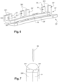
- the two conductive bodies 34, 34' are not electrically connected, each of the conductive elements making it possible to connect one of the two three-phase systems. All the legs 31, 32, 33, 31', 32', 33' are bent at the same inclination and all the radial end surfaces 300 of the legs are parallel for this interconnector, as illustrated in FIG. figure 6 .
- the legs of the two conductive elements 35 and 35' will advantageously be intercalated, that is to say that two adjacent legs of the interconnector 30 in the circumferential direction will belong to two different conductive elements.
- the first three ends 240 of the first three-phase system are electrically connected to the first conductive element 35, and the other three first ends of the second three-phase system are electrically connected to the second conductive element 35'.
- the conductive bodies extend substantially parallel to one another, thus forming a constant gap between the conductive bodies 34, 34' substantially over the entire length over which the conductive elements extend, a layer of electrically insulating material being, for example, interposed between the two conductive elements.
- the conductive elements 35, 35' are partially overmolded with an insulating material, thus forming the interconnector.
- the insulating material may be a plastic material reinforced with fibers or a resin.
- the two conductive bodies 34, 34' extend next to each other along the circumference of the winding.
- the first conductor ends 240 each come out parallel and are slightly inclined at the same angle to be brought opposite a connection surface 300 of a tab to be fixed and each is directly connected to the connection surface 300 of the opposite tab.
- the portions of winding conductors 240 to be interconnected are interconnection ends of the same phase of a winding to be brought back to the same potential, for example.
- the interconnector 30 may comprise retaining clips 36 in particular for the second conductor ends 242 intended to be connected to the electronics, as explained above.
- Such clips 36 make it possible in particular to retain these second conductor ends 242 and to direct them towards the electronics.
- Such retaining clips 36 extend for example in the plane of the interconnector and are in the form of jaws.
- the clips 36 are advantageously integral with the interconnector 30.
- the clips extend, for example, in the extension plane of the housing, transversely to the X axis of the machine.
- the clips are thus advantageously transverse to the output direction of the conductor ends to be directed towards the control electronics.
- the clips are, for example, integral with the housing.
- the clips are for example in the form of deformable jaws, adapted to insert the conductor ends into them by force.
- the clips are in the form of non-deformable jaws, the conductor ends being slid into the jaws when mounting the interconnector on the winding.
- the retaining clips are guiding means in a first embodiment.
- the guide means are holes drilled in the housing, along the axis of the machine for example, that is to say advantageously transverse to the output direction of the conductor ends to be directed towards the control electronics.
- At least one of the holes has a shape adapted to insert a die-cast conductor whose section is therefore variably circular and rectangular.
- the hole has a shape as illustrated in the figure figure 9 with in particular a rounded part and a straight part.
- the clearance between the wire and the hole is in particular as small as possible to be able to completely block the conductor in the hole simply by adding a little varnish.
- Each first end of conductor 240 is advantageously fixed to the opposite lug to which it will have to be connected, by laser welding, illustrated in figure 7 .
- the welding is carried out at the free end surface of the tab 301, and at an end surface to be welded 241 of the end of the conductor.
- These end surfaces 241 and 301 are advantageously substantially of the same dimension, with a difference of the order of 20 percent.
- the end of the conductor 240 will first be cut cleanly, then a tool bends and holds this end of the conductor to be welded in contact with the support surface 300 of the tab.
- the surfaces of the free ends 301 of the legs 31, 32, 33, 31', 32', 33' will advantageously be substantially all contained in the same plane, for example transverse to the X axis. This simplifies the process of fixing the legs by minimizing for example the movement of a possible laser head in the case of welding of the successive legs on the corresponding conductor portions by such a head, described below.
- the end surfaces to be welded 241 are then also advantageously substantially contained in this same plane, which will be the welding plane.
- the welding plane therefore includes both the surfaces to be welded of the ends of conductors 241 and free ends 301 of the legs corresponding, this makes it possible to simplify the sequence of welds by not having to modify the height of the laser 38 for firing.
- the ends of conductors 241 are in parallel planes.
- the free ends 301 are also in parallel planes.
- leg and the portion of conductor 240 makes it possible to further improve the welding, such as almost pure copper in particular.
- the end of conductor 240 to be soldered will be stripped for example over a height along X of 4 mm, advantageously 3 mm, from the surface to be soldered 241, and a lug length of 4 mm along the X axis will advantageously protrude from the plastic overmolding of the interconnector 30.
- the conductor end 240 will thus advantageously be sufficiently stripped and the free end surface 301 of the tab sufficiently far from the plastic of the interconnector 30 so that the heat generated by the laser shot near the soldering point does not risk burning the enamel of the conductor or the plastic of the interconnector, which could generate gases and projections of material.
- gases being able to contaminate the solder and generate the appearance of bubbles inside and the projections of materials being able to contaminate the solder in progress, the neighboring tabs, the stator and the tools are thus avoided as much as possible.
- the axis of the laser 38 performing the welding is used perpendicular to the welding plane, therefore along the axis of the legs here typically.
- a bispot laser will be used (firing at two points and not just one), allowing simultaneous firing on the two surfaces to be welded 241 and 301. This will in particular allow welding despite a slight axial offset between the tab and the end of the conductor 240.
- the conductive elements 35, 35' are for example positioned substantially parallel to one above the other along the X axis in a mold. By one above the other, it will be understood that the two conductive elements are in planes substantially perpendicular to the X axis and different.
- the X axis is advantageously transverse to the extension planes of the bodies of the conductive elements 34, 34'.
- the conductive bodies extend substantially parallel to one another, thus forming a constant gap between the conductive bodies 34, 34' substantially over the entire length over which the conductive elements extend.
- the connectors may be offset around the X axis, or alternatively possibly inclined, i.e. contained in planes which are not perfectly perpendicular to the X axis.
- each conductive element 35 comprises a holding portion 37 making it possible to hold each conductive element axially, and to hold the conductive elements one above the other, at a distance from each other, during the molding of the housing.
- the axial holding portion 37 is for example a tab extending in projection from the body 34 of the conductive element, for example in the plane of the body 34.
- the tab comprises an opening 370 such as a through hole in the direction transverse to the plane of extension of the body.
- the opening 370 is adapted to insert an axial holding device 371 therein.
- the axial holding device 371 of a conductive element has for example the form of two end pieces each extending along the axis X, mounted on either side of the tab, at least one of the two being inserted at least partially into the opening 370, the end pieces being adapted to cooperate together during assembly, to axially hold the conductive element 35, as illustrated in FIG. figure 8 .
- Such a holding device 371 also ensures the angular holding of the conductive element 35 in the mold.
- the end pieces and the opening are for example circular in cross-section.
- the conductive element is then always free to rotate around the axial holding device at this stage.
- the end pieces and the opening have an oblong or parallelepiped section, which also limits the rotation of the conductive element around the axial holding device.
- the holding portions of the two conductive elements 37 and 37' are arranged such that at least a portion of the first holding portion 37 does not axially overlap at least a portion of the second holding portion 37'.
- the holding portions 37, 37' of the two conductive elements are for example angularly offset about the transverse direction.
- the holding devices for each of the conductive elements can thus be mounted from above and below each conductive element, with both accesses being available.
- each conductive element 35, 35' is held axially and angularly in the mold, by a specific axial holding device 371, 371', mounted on either side of the tab.
- each conductive element 35, 35' extends angularly from a first end to a second end in the trigonometric direction.
- the holding portion 37 is for example closer to the first end than to the second end for the first conductive element 35, and the holding portion 37' is closer to the second end than to the first end for the second conductive element 35'.
- the holding portions 37, 37' are therefore effectively axially spaced apart.
- the devices for holding each of the conductive elements 35, 35' may, for example, extend from the mold used to produce the housing molding.
- the holding portion 37 is part of the body 34 of the conductive element 35, in a configuration in which the body 34' of the conductive element 35' locally has a cutout axially releasing said holding portion 37 in the transverse direction.
- the conductive element 35 advantageously comprises a support flat 39 formed on the edge of the conductive element, that is to say substantially parallel to the axis X.
- the support flat 39 is placed in radial abutment against the mold for producing the body.
- Such a flat makes it possible to position the conductive element against the mold and to limit the radial movement of the conductive element during molding, by limiting the possible rotation of the conductive element around the axial holding device.
- the mold advantageously has a draft angle provided so that the plastic can be easily removed from the mold.
- the support flat 39 is in radial contact with the mold at only one of its two edges along the edge along the X axis. This allows molding all around the conductive elements except at the edge which is glued to the mold.
- the support flat 39 is for example closer to the second end than to the first end for the first conductive element 35, and the support flat 39' is closer to the first end than to the second end for the second conductive element 35'.
- the support flat 39 of the first conductive element is therefore angularly opposite along the conductive element to the holding portion 37 of the first conductive element and likewise for the second conductive element.
- the support flats 39, 39' are therefore angularly spaced from each other.
- the angular distance between the two flats 39 and 39' makes it possible to limit the risk of short-circuiting by salt bridge.
- each conductive element is first placed in position by the axial holding device 371 then placed in abutment using the support flat 39 and finally held tight by an axial support device 381.
- each conductive element will also advantageously comprise an axial support surface 38, 38' adapted to receive in axial support on either side of said surface the axial support device 381.
- Such an axial support device makes it possible to clamp the conductive element in position to prevent radial movement of the conductive element.
- the axial bearing surface 38 is advantageously a part of the body 34 of the conductive element.
- the axial bearing surface is substantially flat and substantially perpendicular to the axis X and the axial bearing device extending along the axis X comes to bear on either side of the surface 38.
- the support device 381 is for example composed of two rods, one resting above and the other resting below opposite the rod resting above.
- the axial support surface 38 is advantageously closer to the end of the conductive element opposite the end of the conductive element closest to the holding portion 37.
- the angular distance between the axial support surfaces 38, 38' also makes it possible to limit the risk of short circuit by salt bridge.
- the insulating material is then injected to form the interconnector housing molded around the two conductive elements.
- the material insulating material may be a plastic material reinforced with fibers or even a resin.
- the two axial holding devices 371, 371' which are not embedded in the molded housing, can be removed, for example, at the same time as the mold is removed.
- the axial support devices 381, 381' are also removed.
- the end pieces of the axial retaining devices 371, 371' will advantageously be of small diameter to leave only small diameter holes in the housing after molding.
- the support devices After removal of the support devices, two non-through holes also remain in the housing thus molded at the level where the support devices were mounted.
- the support devices will also advantageously be small diameter rods to leave only very small diameter holes in the housing after molding.
- each conductive element of the interconnector thus molded are distributed along the arc of the interconnector advantageously following the curvature of the interconnector, as illustrated in figure 3
- the legs of each conductive element are advantageously angularly close, that is to say separated by a small angular distance which advantageously corresponds to the distance separating the first ends of the conductive element.
Landscapes
- Engineering & Computer Science (AREA)
- Power Engineering (AREA)
- Insulation, Fastening Of Motor, Generator Windings (AREA)
- Manufacture Of Motors, Generators (AREA)
Description
- L'invention porte sur un interconnecteur à pattes de connexion de portion de conducteur de bobinage, inclinées par rapport à l'axe de la machine sur laquelle l'interconnecteur est monté.
- De façon connue en soi, les machines électriques tournantes comportent un stator et un rotor solidaire d'un arbre. Le rotor peut être solidaire d'un arbre menant et/ou mené et peut appartenir à une machine électrique tournante sous la forme d'un alternateur, d'un moteur électrique, ou d'une machine réversible pouvant fonctionner dans les deux modes.
- Par ailleurs, le stator est monté dans un carter configuré pour porter à rotation l'arbre par exemple par l'intermédiaire de roulements. Le stator comporte un corps constitué par un empilage de tôles minces formant une culasse en forme de couronne dont la face intérieure est pourvue d'encoches ouvertes vers l'intérieur pour recevoir un bobinage.
- Dans un bobinage de type ondulé, les enroulements de phase sont formés chacun à partir d'au moins un conducteur de bobinage, tel qu'un fil continu, recouvert d'une couche isolante, en particulier une couche d'émail. Alternativement, le bobinage est obtenu à partir de conducteurs de bobinage en forme d'épingles reliées électriquement entre eux par exemple par soudage.
- Des portions de conducteur de bobinage doivent être reliées électriquement via un interconnecteur pour obtenir un couplage électrique souhaité de la machine, par exemple en triangle ou en étoile, comme cela est connu des documents
US2013/249334 ,DE102007034327 ouEP3280034 . A cet effet, des connexions électriques entre ces portions de conducteurs de bobinage et des pattes de l'interconnecteur seront nécessaires. - Dans de tels interconnecteurs connus du document
US 2014/0183993 , l'opération de connexion électrique des portions de conducteurs de bobinage aux pattes de l'interconnecteur, peut être rendue complexe par la proximité entre les portions de conducteur et le palier arrière dans lequel il est monté notamment, et à l'issue de l'opération de connexion, les portions de conducteur connectées créent un encombrement important à l'origine notamment d'un risque de formation de ponts salins. - La présente invention vise à remédier efficacement à ces inconvénients en proposant un interconnecteur selon la revendication 1.
- Une telle configuration de pattes inclinées par rapport à l'axe de la machine permet de gagner un jeu axial et un jeu radial entre le palier arrière et la soudure. Ce jeu supplémentaire permet d'avoir un encombrement plus faible et réduit les risques de ponts salins.
- Selon une réalisation, la distance à l'axe diminue continûment au fur et à mesure que l'on se rapproche de l'extrémité libre.
- Selon une réalisation, dans un plan de coupe perpendiculaire à l'axe, les pattes présentent sensiblement une même distance à l'axe, quel que soit le plan de coupe perpendiculaire à l'axe.
- Selon l'invention, les surfaces d'extrémité radiale des pattes sont parallèles. Cela permet de simplifier le procédé de connexion de l'interconnecteur en facilitant l'approche des portions de conducteur du bobinage
- Selon une réalisation, l'interconnecteur comprend également des clips de maintien d'autres conducteurs de bobinage adaptés pour diriger une autre portion de conducteur de bobinage vers une électronique de commande. Cela permet de faciliter le maintien des conducteurs allant vers l'électronique tout diminuant l'impact des vibrations sur ces conducteurs et donc en diminuant le risque de casse.
- Selon une réalisation, l'interconnecteur comprend également au moins un corps conducteur, les pattes étant connectées entre elles par le corps conducteur. Cette structure d'interconnecteur est simple à réaliser et compacte.
- Selon une réalisation, les surfaces libres des pattes sont sensiblement parallèles. Cela permet de simplifier l'étape de soudure sans avoir à changer la hauteur de l'appareil de soudage par exemple du laser.
- L'invention concerne également une machine comprenant un bobinage statorique s'étendant autour de l'axe selon une direction circonférentielle, un interconnecteur tel que précédemment décrit. Selon l'invention, les pattes de l'interconnecteur sont disposées le long de la direction circonférentielle du bobinage statorique. Cela permet de minimiser les mouvements de l'appareil de soudure et donc de simplifier le procédé de connexion du bobinage. Selon une réalisation, la portion de conducteur de bobinage est fixée à la surface de connexion de la patte par soudure laser.
- Selon une réalisation, chaque patte de l'interconnecteur est connectée à une portion de conducteur du bobinage appartenant à une phase distincte du bobinage. Cela permet de réaliser le point neutre ou le couplage en triangle dudit bobinage statorique.
- L'invention sera mieux comprise à la lecture de la description qui suit et à l'examen des figures qui l'accompagnent. Ces figures ne sont données qu'à titre illustratif mais nullement limitatif de l'invention.
- La
figure 1 est une vue en coupe partielle d'une machine électrique tournant destinée à porter un interconnecteur selon la présente invention; - La
figure 2 est une vue en perspective du stator portant l'interconnecteur selon l'invention assurant le couplage des portions de conducteur de bobinage; - La
figure 3 montre une vue en perspective de l'interconnecteur selon la présente invention; - La
figure 4 montre une patte de l'interconnecteur inclinée connectée à une portion de conducteur selon la présente invention; - La
figure 5 est une vue de dessus de l'interconnecteur selon la présente invention; - La
figure 6 est une vue en perspective des éléments conducteurs de l'interconnecteur selon la présente invention hors surmoulage; - La
figure 7 illustre la fixation des pattes aux portions de conducteur par soudure laser. - Les
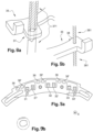
figures 8a et 8b sont des vues de détail des dispositifs de maintien et d'appui pour le moulage du boitier sur les deux éléments conducteurs ;. - La
figure 9a est une vue de dessus de l'interconnecteur illustrant des moyens de guidage étant des trous percés dans le boitier; - La
figure 9b illustre une forme particulière des moyens de guidage de lafigure 9a ; - Les éléments identiques, similaires, ou analogues conservent la même référence d'une figure à l'autre.
- La
figure 1 représente une machine électrique tournante 10 compacte et polyphasée, notamment pour véhicule automobile. Cette machine électrique tournante transforme de l'énergie mécanique en énergie électrique, en mode alternateur, et peut fonctionner en mode moteur pour transformer de l'énergie électrique en énergie mécanique. Cette machine électrique tournante est, par exemple, un alternateur ou une machine réversible. - La machine électrique tournante comporte un carter 11. A l'intérieur de ce carter, elle comporte, en outre, l'arbre 12, le rotor 13 solidaire en rotation de l'arbre et le stator 14 entourant le rotor. Le mouvement de rotation du rotor 12 se fait autour d'un axe X, qui est l'axe de la machine. Dans la suite de la description les orientations radiales, ortho-radiale et axiales sont à considérer par rapport à cet axe X. Dans la suite de la description la partie arrière est la partie de la machine comprenant l'électronique et la partie avant est la partie de la machine du côté de la poulie.
- Dans cet exemple, le carter 11 comporte un palier avant 15 et un palier arrière 16 qui sont assemblés ensemble. Ces paliers sont de forme creuse et portent, chacun, centralement un roulement à billes respectif pour le montage à rotation de l'arbre 12.
- Une poulie 17 est fixée sur une extrémité avant de l'arbre 12, au niveau du palier avant. Cette poulie 17 permet de transmettre le mouvement de rotation à l'arbre. L'extrémité arrière de l'arbre 12 porte un collecteur 18. Un porte-balais 21 alimente le rotor via le collecteur et est relié à un régulateur (non représenté) de tension compris dans un pont redresseur.
- Le palier avant 15 et le palier arrière 16 peuvent comporter, en outre, des ouvertures 27 sensiblement latérales pour le passage de l'air en vue de permettre le refroidissement de la machine électrique tournante par circulation d'air engendrée par la rotation d'un ventilateur 28 avant sur la face avant du rotor, c'est-à-dire au niveau du palier avant et d'un ventilateur arrière 19 sur la face arrière du rotor, c'est-à-dire au niveau du palier arrière.
- Dans cet exemple de réalisation, le stator 14 comporte un corps en forme d'un paquet de tôles 23 doté d'encoches, par exemple du type semi fermée ou ouverte, équipées d'isolant d'encoches pour le montage d'un bobinage statorique 24. Le corps de stator a une forme cylindrique annulaire d'axe X. Le bobinage 24 traverse les encoches du corps et forme un chignon avant 25 et un chignon arrière 26 de part et d'autre du corps du stator 14.
- Le bobinage s'étend selon une direction circonférentielle autour de l'axe X tout le long du corps du stator. Le bobinage 24 s'étend par ailleurs radialement entre une périphérie intérieure de bobinage plus proche de l'axe X et une périphérie extérieure de bobinage plus proche du palier.
- Dans cet exemple, le rotor 13 est un rotor à griffe comportant deux roues polaires. Lorsque le rotor 13 est magnétisé et devient un rotor inducteur avec formation de pôles magnétiques Nord-Sud, un courant induit alternatif est créé dans le bobinage 24 du stator 14 induit par la rotation de l'arbre 12.
- Un pont redresseur formé par des modules électroniques de puissance (non représentés) transforme alors ce courant induit alternatif généré par la machine en un courant continu, notamment pour alimenter les charges et les consommateurs du réseau de bord du véhicule automobile ainsi que pour recharger sa batterie. Ces modules ou d'autres modules de puissance pourront également être commandés pour injecter du courant dans les différentes phases de la machine électrique lorsque cette dernière fonctionne en mode moteur.
- Le bobinage statorique 24 est composé d'une pluralité de conducteurs formant les phases. Plus précisément, chaque phase comprend une première extrémité de conducteur électrique 240 formant un point neutre électrique, une deuxième extrémité de conducteur électrique 242 formant un point de connexion d'une sortie de phase, les terminaux de connexion de phase étant donc formés par deux extrémités de conducteur.
- Les deuxièmes extrémités de conducteur 242 sont reliées électriquement aux modules électroniques de puissance.
- Dans ce qui suivra, on entendra par circonférence statorique une courbe parmi les courbes épousant la position moyenne du bobinage statorique. Une circonférence statorique sera par exemple donnée par un cercle centré sur l'axe X et passant par les extrémités des conducteurs.
- Dans ce qui suivra, on entendra par secteur angulaire l'angle défini le long du bobinage statorique, depuis le centre de la machine, autour de l'axe X, dans un plan orthogonal à l'axe de la machine
- Avantageusement, comme illustré à la
figure 2 , les extrémités de conducteur 240, 242 sont donc sur la même circonférence statorique et s'étendent le long d'un secteur angulaire du stator 14. L'écart angulaire entre les premières extrémités des phases 240 est constant le long du secteur angulaire dans laquelle se situent les extrémités, tel que cela est montré sur lafigure 2 . De la même manière l'écart angulaire entre les deuxièmes extrémités des phases 242 est constant le long du secteur angulaire dans laquelle elles se situent. Les extrémités de conducteur sont en sortie de bobinage, sensiblement orientés selon l'axe X. - Dans un premier mode de réalisation, le bobinage est un bobinage tri-phasé. Les portions de conducteurs de bobinage 240 à interconnecter sont alors les premières extrémités de conducteur électrique, à relier au point neutre électriquement.
- Les premières extrémités 240 connectées au point neutre sont reliées au moyen d'un interconnecteur 30 visible sur la
figure 2 . Cet interconnecteur 30 s'étend suivant une forme en arc de cercle sur un secteur angulaire d'angle α autour de l'axe X au-dessus du chignon avant (ou arrière), c'est-à-dire dans un plan orthogonal à l'axe de la machine X. L'interconnecteur 30 s'étend suivant un secteur angulaire limité compris entre 30° et 90°. L'interconnecteur 30 suit avantageusement la courbure autour de l'axe X du chignon avant, sous forme d'un arc. - L'interconnecteur 30 positionné sensiblement entre les périphéries intérieure et extérieure du bobinage, peut dépasser notamment radialement du bobinage statorique.
- L'interconnecteur 30 comprend avantageusement trois pattes 31, 32, 33, électriquement conductrices, décalées angulairement. Les pattes 31, 32, 33 sont distribuées le long de l'arc de l'interconnecteur en suivant avantageusement la courbure de l'interconnecteur, comme illustré à la
figure 3 . Les pattes sont avantageusement angulairement proches c'est-à-dire séparées d'une faible distance circonférentielle qui correspond avantageusement à la distance séparant les premières extrémités de conducteur. - Chaque patte de l'interconnecteur positionnée radialement entre l'axe de la machine et le palier, s'étend dans une direction inclinée par rapport à l'axe X. Les pattes de l'interconnecteur s'étendent avantageusement du même côté du bobinage statorique 24 que les extrémités des conducteurs 240, 242.
- Un corps conducteur 34 relie avantageusement électriquement les pattes entre elles. Le corps 34 s'étend par exemple dans un plan d'extension de l'interconnecteur 30 et les pattes 31, 32, 33 s'étendent depuis le corps de l'interconnecteur 34. Les pattes s'étendent par exemple selon une première portion 341 contenue dans le plan du corps puis une portion adjacente 342 transverse à la portion précédente et s'étendant selon une direction inclinée par rapport à l'axe X, comme illustré sur la
figure 3 . Les pattes ont ainsi une forme coudée, la portion adjacente 342 n'étant pas coaxiale avec l'axe X de la machine. - Une telle forme pourra notamment être obtenue par pliage des pattes. Ce pliage des pattes peut être effectué en plusieurs étapes ou en une seule étape en fonction de l'angle final souhaité.
- Comme illustré à la
figure 4 , chaque patte de fixation présente donc une distance variable à l'axe au fur et à mesure que l'on se rapproche de son extrémité libre. En particulier la portion adjacente 342 aura une distance à l'axe variable au fur et à mesure que l'on se rapproche de son extrémité libre. La distance pourra par exemple avantageusement diminuer continûment depuis l'extrémité reliée à la première portion 341 jusqu'à l'extrémité libre 301. On entend par diminuer continûment que la distance entre la portion et l'axe diminue de manière linéaire et plus précisément de manière proportionnelle à la hauteur de la portion par rapport au corps 34. - Chaque patte présente une surface d'extrémité radiale 300 illustrée à la
figure 3 , avantageusement portée par la portion adjacente 342, c'est-à-dire la portion de la patte adjacente à l'extrémité libre 301 de la patte. - Les pattes sont par exemple à section rectangulaire dans le plan transverse à leur direction d'extension, de sorte que la surface d'extrémité radiale 300 est opposée à une surface opposée, les deux surfaces étant séparées par le conducteur, l'une des surfaces étant en regard du palier et la surface opposée étant en regard de l'axe X de la machine, les deux surfaces étant séparées par une faible épaisseur.
- Ainsi la première portion 341 et la portion adjacente 342 d'une patte font avantageusement un angle β entre elles dans un plan contenant l'axe X et perpendiculaire à la surface d'extrémité radiale 300 de la patte. L'angle β aura une valeur avantageusement comprise entre 20° et 85° et notamment comprise entre 60° et 85°.
- Un élément conducteur est ainsi formé par ledit corps 34 et les pattes 31, 32, 33. Les pattes d'un élément conducteur ont avantageusement toute sensiblement la même inclinaison par rapport à l'axe X. Ainsi dans un plan de coupe perpendiculaire à l'axe X, les pattes 31, 32 présentent sensiblement une même distance à l'axe, quel que soit le plan de coupe perpendiculaire à l'axe.
- La surface d'extrémité radiale 300 définit une surface de connexion pour une première extrémité du conducteur 240. Une faible inclinaison de la première extrémité de conducteur 240 permet de l'amener en contact avec la surface d'extrémité radiale 300 pour connexion.
- D'une patte à l'autre, ces surfaces d'extrémité radiale 300 sont parallèles, comme illustré à la
figure 5 . Les surfaces de connexion étant parallèles, cela permet de faciliter l'approche des portions de conducteurs pour la connexion selon une direction commune. - Dans une variante du premier mode de réalisation, le stator 14 présente un bobinage double triphasé. L'interconnecteur 30 comprend alors deux éléments conducteurs 35 et 35'. Chaque élément conducteur est formé du corps conducteur 34, 34' connectant électriquement trois pattes 31, 32, 33 et 31', 32', 33' entre elles. Les deux corps conducteurs 34, 34' sont non électriquement connectés, chacun des éléments conducteurs permettant de connecter un des deux systèmes triphasés. Toutes les pattes 31, 32, 33, 31', 32', 33' sont coudées selon la même inclinaison et toutes les surfaces d'extrémité radiales 300 des pattes sont parallèles pour cet interconnecteur, comme illustré à la
figure 6 . - Les pattes des deux éléments conducteurs 35 et 35' seront avantageusement intercalées c'est-à-dire que deux pattes adjacentes de l'interconnecteur 30 selon la direction circonférentielle appartiendront à deux éléments conducteurs différents.
- Afin d'établir les connexions, les trois premières extrémités 240 du premier système triphasé sont reliées électriquement au premier élément conducteur 35, et les trois autres premières extrémités du deuxième système triphasé sont reliées électriquement au deuxième élément conducteur 35'. Comme on peut le voir sur la
figure 6 , les corps conducteurs s'étendent sensiblement parallèlement l'un par rapport à l'autre formant ainsi un écart constant entre les corps conducteurs 34, 34' sensiblement sur toute la longueur sur laquelle s'étendent les éléments conducteurs, une couche de matériau électriquement isolant étant par exemple interposée entre les deux éléments conducteurs. - En variante les éléments conducteurs 35, 35' sont partiellement surmoulés par une matière isolante, formant ainsi l'interconnecteur. La matière isolante pourra être une matière plastique renforcée par des fibres ou encore une résine.
- En variante les deux corps conducteurs 34, 34' s'étendent l'un à côté de l'autre le long de la circonférence du bobinage.
- Sans déviation nécessaire du fil, les premières extrémités de conducteur 240 sortent chacune parallèle et sont légèrement inclinées d'un même angle pour être amenées en regard d'une surface de connexion 300 d'une patte à fixer et chacune est directement connectée sur la surface de connexion 300 de la patte en regard.
- Dans un deuxième mode de réalisation non illustré, les portions de conducteurs de bobinage 240 à interconnecter sont des extrémités d'interconnexion d'une même phase d'un bobinage à ramener au même potentiel, par exemple.
- Quel que soit le mode de réalisation, l'interconnecteur 30 pourra comprendre des clips de maintien 36 notamment pour les deuxièmes extrémités de conducteur 242 destinées à être connectées à l'électronique, comme expliqué précédemment. De tels clips 36 permettent notamment de maintenir ces deuxièmes extrémités de conducteur 242 et de les diriger vers l'électronique. De tels clips de maintien 36 s'étendent par exemple dans le plan de l'interconnecteur et se présentent sous la forme de mâchoires. Les clips 36 sont avantageusement venus de matière avec l'interconnecteur 30.
- Les clips s'étendent par exemple dans le plan d'extension du boitier, transversalement à l'axe X de la machine. Les clips sont ainsi avantageusement transverses à la direction de sortie des extrémités de conducteurs à diriger vers l'électronique de commande. Les clips sont par exemple venus de matière avec le boitier.
- Les clips se présentent par exemple sous forme de mâchoire déformable, adaptées pour y insérer les extrémités de conducteur en force. En variante, les clips se présentent sous forme de mâchoires non déformable, les extrémités de conducteurs étant glissées dans les mâchoires lors du montage de l'interconnecteur sur le bobinage.
- Les clips de maintien sont des moyens de guidage dans un premier mode de réalistaion.
- En variante, les moyens de guidage sont des trous percés dans le boitier, selon l'axe de la machine par exemple, c'est-à-dire avantageusement transverses à la direction de sortie des extrémités de conducteurs à diriger vers l'électronique de commande.
- Au moins un des trous a notamment une forme adaptée pour y insérer un conducteur matricé dont la section est donc variablement circulaire et rectangulaire.
- Le trou a pour cela une forme telle qu'illustrée à la
figure 9 avec notamment une partie arrondie et une partie rectiligne. - Le jeu entre le fil et le trou est notamment le plus petit possible pour pouvoir bloquer totalement le conducteur dans le trou simplement par ajout d'un peu vernis.
- Chaque première extrémité de conducteur 240 est avantageusement fixée à la patte en regard à laquelle elle devra être connectée, par soudure laser, illustrée à la
figure 7 . La soudure est réalisée au niveau de la surface d'extrémité libre de la patte 301, et d'une surface d'extrémité à souder 241 de l'extrémité du conducteur. Ces surfaces d'extrémité 241 et 301 sont avantageusement sensiblement de même dimension, avec un écart de l'ordre de 20 pourcents. - En pratique l'extrémité du conducteur 240 sera préalablement coupée net, puis un outillage plie et maintien cette extrémité de conducteur à souder en appui sur la surface d'appui 300 de la patte.
- Les surfaces des extrémités libres 301 des pattes 31, 32, 33, 31', 32', 33' seront avantageusement sensiblement toutes contenues dans un même plan, par exemple transverse à l'axe X. Cela simplifie le processus de fixation des pattes en minimisant par exemple le déplacement d'une éventuelle tête laser dans le cas d'une soudure des pattes successives sur les portions de conducteurs correspondantes par une telle tête, décrite par la suite.
- Les surfaces d'extrémité à souder 241 sont alors également avantageusement sensiblement contenues dans ce même plan, qui sera le plan de soudure.
- Le plan de soudure comprenant donc à la fois les surfaces à souder des extrémités de conducteurs 241 et extrémités libres 301 des pattes correspondantes, ceci permet de simplifier l'enchainement des soudures en ayant notamment pas à modifier la hauteur du laser 38 pour le tir.
- En variante les extrémités de conducteurs 241 sont dans des plans parallèles. De même les extrémités libres 301 sont également dans les plans parallèles.
- Le choix de deux matériaux identiques pour la patte et la portion de conducteur 240 permet d'améliorer encore la soudure, comme un cuivre quasi pur notamment.
- L'extrémité de conducteur 240 à souder sera dénudée par exemple sur une hauteur selon X de 4mm, avantageusement 3mm, depuis la surface à souder 241, et une longueur de patte de 4 mm selon l'axe X dépassera avantageusement du surmoulage plastique de l'interconnecteur 30.
- L'extrémité de conducteur 240 sera ainsi avantageusement suffisamment dénudée et la surface d'extrémité libre 301 de la patte suffisamment éloignée du plastique de l'interconnecteur 30 pour que la chaleur générée par le tir laser à proximité du point de soudure ne risque pas de brûler l'émail du conducteur ou le plastique de l'interconnecteur, pouvant générer des gaz et des projections de matière. De tels gaz pouvant contaminer la soudure et générer l'apparition de bulle à l'intérieur et les projections de matières pouvant contaminer la soudure en cours, les pattes voisines, le stator et les outillages sont ainsi évités autant que possible.
- L'axe du laser 38 réalisant la soudure est utilisé perpendiculairement au plan de soudure, donc selon l'axe des pattes ici typiquement.
- On utilisera un laser bispot (tir en deux points et non en un seul), permettant de tirer simultanément sur les deux surfaces à souder 241 et 301. Cela permettra notamment de souder malgré un léger décalage axial entre la patte et l'extrémité de conducteur 240.
- Pour fabriquer l'interconnecteur, les éléments conducteurs 35, 35' sont par exemple positionnés sensiblement parallèlement l'un au-dessus de l'autre selon l'axe X dans un moule. On entendra par l'un au-dessus de l'autre que les deux éléments conducteurs sont dans des plans sensiblement perpendiculaires à l'axe X et différents.
- L'axe X est avantageusement transverse aux plans d'extension des corps des éléments conducteurs 34, 34'. Comme on peut le voir sur la
figure 6 , les corps conducteurs s'étendent sensiblement parallèlement l'un par rapport à l'autre formant ainsi un écart constant entre les corps conducteurs 34, 34' sensiblement sur toute la longueur sur laquelle s'étendent les éléments conducteurs. - Les connecteurs pourront être décalés autour de l'axe X, ou en variante éventuellement inclinés c'est-à-dire contenu dans des plans n'étant pas parfaitement perpendiculaires à l'axe X.
- Un bon maintien des éléments conducteurs 35, 35' sera nécessaire préalablement à toute étape de moulage, une forte pression exercée sur les éléments conducteurs, notamment par l'injection du plastique dans le moule pour former l'interconnecteur, risquant de les déplacer ou même de les déformer.
- Pour cela chaque élément conducteur 35 comprend une portion de maintien 37 permettant de maintenir axialement chaque élément conducteur, et de maintenir les éléments conducteurs l'un au-dessus de l'autre, à distance l'un de l'autre, lors du moulage du boitier.
- Comme illustré à la
figure 6 , la portion de maintien axial 37 est par exemple une languette s'étendant en saillie depuis le corps 34 de l'élément conducteur, par exemple dans le plan du corps 34. La languette comprend une ouverture 370 telle qu'un trou traversant dans la direction transverse au plan d'extension du corps. - L'ouverture 370 est adaptée pour y insérer un dispositif de maintien axial 371.
- Le dispositif de maintien axial 371 d'un élément conducteur a par exemple la forme de deux embouts s'étendant chacun selon l'axe X, montés de part et d'autre de la languette, au moins l'un des deux s'insérant au moins partiellement dans l'ouverture 370, les embouts étant adaptés pour coopérer ensemble au montage, pour maintenir axialement l'élément conducteur 35, comme illustré à la
figure 8 . Un tel dispositif de maintien 371 assure aussi le maintien angulaire de l'élément conducteur 35 dans le moule. - Les embouts et l'ouverture sont par exemple à section circulaire. L'élément conducteur est alors toujours libre en rotation autour du dispositif de maintien axial à ce stade.
- En variante les embouts et l'ouverture sont à section oblongue ou parallélépipédique, ce qui limite également la rotation de l'élément conducteur autour du dispositif de maintien axial.
- Les portions de maintien des deux éléments conducteurs 37 et 37' sont disposées de sorte qu'au moins une partie de la première portion de maintien 37 ne chevauche pas axialement au moins une partie de la deuxième portion de maintien 37'. Les portions de maintien 37, 37' des deux éléments conducteurs sont par exemple décalées angulairement autour de la direction transverse.
- Les dispositifs de maintien de chacun des éléments conducteurs peuvent ainsi être montés par au-dessus et par en dessous de chaque élément conducteur, ces deux accès étant disponibles.
- Ainsi chaque élément conducteur 35, 35' est maintenu axialement et angulairement dans le moule, par un dispositif de maintien axial propre 371, 371', monté de part et d'autre de la languette.
- En particulier, chaque élément conducteur 35, 35' s'étend angulairement d'une première extrémité vers une deuxième extrémité dans le sens trigonométrique. La portion de maintien 37 est par exemple plus proche de la première extrémité que de la deuxième extrémité pour le premier élément conducteur 35, et la portion de maintien 37' est plus proche de la deuxième extrémité que de la première extrémité pour le deuxième élément conducteur 35'. Lorsque les deux éléments conducteurs sont l'un au-dessus de l'autre, les portions de maintien 37, 37' sont donc effectivement axialement éloignées.
- La distance entre les deux méplats 37 et 37' de chaque élément conducteur permet de limiter le risque de court-circuit par pont salin.
- Les dispositifs de maintien de chacun des éléments conducteurs 35, 35' pourront par exemple s'étendre depuis le moule utilisé pour la réalisation du moulage boitier.
- En variante, la portion de maintien 37 fait partie du corps 34 de l'élément conducteur 35, dans une configuration dans laquelle le corps 34' de l'élément conducteur 35' présente localement une découpe dégageant axialement ladite portion de maintien 37 selon la direction transverse.
- De plus l'élément conducteur 35 comprend avantageusement un méplat d'appui 39 formé sur la tranche de l'élément conducteur, c'est-à-dire sensiblement parallèlement à l'axe X. Le méplat d'appui 39 est mis en butée radiale contre le moule pour la réalisation du corps. Un tel méplat permet de mettre en position l'élément conducteur contre le moule et de limiter le mouvement radial de l'élément conducteur lors du moulage, en limitant la rotation possible de l'élément conducteur autour du dispositif de maintien axial.
- Le moule a avantageusement un angle de dépouille prévu pour que l'on puisse facilement retirer le plastique du moule. Ainsi le méplat d'appui 39 est en contact en appui radial sur le moule au niveau d'une seule de ses deux arêtes le long de la tranche selon l'axe X. On permet ainsi un moulage tout autour des éléments conducteurs excepté au niveau de l'arête qui est collée au moule.
- Avantageusement, dans la configuration précédente pour chaque élément conducteur 35, 35' s'étendant angulairement d'une première extrémité vers une deuxième extrémité dans le sens trigonométrique, le méplat d'appui 39 est par exemple plus proche de la deuxième extrémité que de la première extrémité pour le premier élément conducteur 35, et le méplat d'appui 39' est plus proche de la première extrémité que de la deuxième extrémité pour le deuxième élément conducteur 35'. Le méplat d'appui 39 du premier élément conducteur est donc angulairement opposé le long de l'élément conducteur à la portion de maintien 37 du premier élément conducteur et de même pour le deuxième élément conducteur.
- Lorsque les deux éléments conducteurs sont l'un au-dessus de l'autre selon l'axe X, les méplats d'appui 39, 39' sont donc angulairement à distance l'un de l'autre. La distance angulaire entre les deux méplats 39 et 39' permet de limiter le risque de court-circuit par pont salin.
- De plus pour éviter la déformation du cuivre lors de l'injection du plastique, pour chaque élément conducteur, des appuis en des points angulairement décalés autour de l'axe X le long de l'interconnecteur 30 seront avantageusement utilisés.
- En effet lors de la fabrication de l'interconnecteur chaque élément conducteur est d'abord mis en position par le dispositif de maintien axial 371 puis mis en butée grâce au méplat d'appui 39 pour finalement être donc maintenu serré par un dispositif d'appui axial 381.
- Pour cela chaque élément conducteur comprendra également avantageusement une surface d'appui axial 38, 38' adaptée pour recevoir en appui axial de part et d'autre de ladite surface le dispositif d'appui axial 381. Un tel dispositif d'appui axial permet de serrer en position l'élément conducteur pour éviter le mouvement radial de l'élément conducteur.
- La surface d'appui axial 38 est avantageusement une partie du corps 34 de l'élément conducteur. La surface d'appui axial est sensiblement plane et sensiblement perpendiculaire à l'axe X et le dispositif d'appui axial s'étendant selon l'axe X vient en appui de part et d'autre de la surface 38.
- Le dispositif d'appui 381 est par exemple composé de deux tiges l'une en appui au-dessus et l'autre en appui en dessous en regard de la tige en appui au-dessus.
- La surface d'appui axial 38 est avantageusement plus proche de l'extrémité de l'élément conducteur opposée à l'extrémité de l'élément conducteur la plus proche de la portion de maintien 37. Ainsi le maintien le long de l'élément conducteur entre la première et la deuxième extrémité de l'élément conducteur 35 par le dispositif de maintien 371 d'un côté et le dispositif d'appui axial 381 de l'autre permet d'éviter au mieux la déformation de l'élément conducteur 35.
- La distance angulaire entre les surfaces d'appui axial 38, 38' permet également de limiter le risque de court-circuit par pont salin.
- La matière isolante est ensuite injectée pour former le boitier de l'interconnecteur moulé autour des deux éléments conducteurs. La matière isolante pourra être une matière plastique renforcée par des fibres ou encore une résine.
- A l'issu du moulage les deux dispositifs de maintien axial 371, 371' n'étant pas noyés dans le boitier moulé peuvent être retirés par exemple en même temps qu'est effectué le retrait du moule. Les dispositifs d'appui axial 381, 381' sont également retirés.
- Après retrait des dispositifs de maintien, deux trous traversant subsistent dans le boitier ainsi moulé au niveau de là où les dispositifs de maintien étaient montés. Les embouts des dispositifs de maintien axial 371, 371' seront avantageusement de faible diamètre pour laisser seulement des trous de faible diamètre dans le boitier après moulage.
- Après retrait des dispositifs d'appui, deux trous non traversant subsistent également dans le boitier ainsi moulé au niveau de là où les dispositifs d'appui étaient montés. Les dispositifs d'appui seront également avantageusement des tiges de faible diamètre pour laisser seulement des trous de très faible diamètre dans le boitier après moulage.
- Les pattes 31, 32, 33 et 31', 32', 33' de chaque élément conducteur de l'interconnecteur ainsi moulé sont distribuées le long de l'arc de l'interconnecteur en suivant avantageusement la courbure de l'interconnecteur, comme illustré à la
figure 3 . Les pattes de chaque élément conducteur sont avantageusement angulairement proches c'est-à-dire séparées d'une faible distance angulaire qui correspond avantageusement à la distance séparant les premières extrémités de l'élément conducteur. - Bien entendu, la description qui précède a été donnée à titre d'exemple uniquement et ne limite pas le domaine de l'invention dont on ne sortirait pas en remplaçant les différents éléments par tous autres équivalents.
- En outre, les différentes caractéristiques, variantes, et/ou formes de réalisation de la présente invention peuvent être associées les unes avec les autres selon diverses combinaisons, dans la mesure où elles ne sont pas incompatibles ou exclusives les unes des autres.
Claims (9)
- Interconnecteur (30) pour l'interconnexion entre deux conducteurs d'un bobinage statorique (24) de machine électrique, s'étendant sur un secteur angulaire (α) autour d'un axe X, l'interconnecteur (30) comprenant au moins deux pattes de fixation électriquement conductrices (31, 32) décalées angulairement, chaque patte de fixation électriquement conductrice présentant une surface d'extrémité radiale (300) définissant une surface de connexion pour une portion de conducteur du bobinage (240) de machine électrique, chaque patte de fixation ayant une extrémité libre (301) caractérisé en ce que ladite patte présente une distance variable à l'axe au fur et à mesure que l'on se rapproche de son extrémité libre, les surfaces d'extrémité radiale (300) des pattes étant parallèles.
- Interconnecteur (30) selon la revendication 1 dans lequel la distance à l'axe diminue continûment au fur et à mesure que l'on se rapproche de l'extrémité libre (301).
- Interconnecteur selon l'une quelconque des revendications précédentes dans lequel, dans un plan de coupe perpendiculaire à l'axe, les pattes (31, 32) présentent sensiblement une même distance à l'axe, quel que soit le plan de coupe perpendiculaire à l'axe.
- Interconnecteur selon l'une quelconque des revendications précédentes comprenant également des clips de maintien d'autres conducteurs de bobinage (36) adaptés pour diriger une autre portion de conducteur de bobinage vers une électronique de commande.
- Interconnecteur selon l'une des revendications précédentes comprenant également au moins un corps conducteur (34), les pattes (31, 32, 33) étant connectées entre elles par le corps conducteur (34).
- Interconnecteur selon l'une quelconque des revendications précédentes dans lequel les surfaces libres (301) des pattes sont sensiblement parallèles.
- Machine comprenant :un bobinage statorique (24) s'étendant autour de l'axe X selon une direction circonférentielle,un interconnecteur (30) selon l'une quelconque des revendications 1 à 6,dans laquelle les pattes (31, 32) de l'interconnecteur (30) sont disposées le long de la direction circonférentielle du bobinage statorique (24).
- Machine selon la revendication 7, dans laquelle la portion de conducteur de bobinage (240) est fixée à la surface de connexion (300) de la patte par soudure laser.
- Machine selon l'une des revendications 7 à 8 dans laquelle chaque patte (31, 32) de l'interconnecteur (30) est connectée à une portion de conducteur du bobinage (240) appartenant à une phase distincte du bobinage.
Applications Claiming Priority (5)
| Application Number | Priority Date | Filing Date | Title |
|---|---|---|---|
| FR1858063A FR3085808B1 (fr) | 2018-09-07 | 2018-09-07 | Machine electrique tournante munie d'un interconnecteur a pattes paralelles |
| FR1858064A FR3085806B1 (fr) | 2018-09-07 | 2018-09-07 | Interconnecteur de machine electrique tournante |
| FR1858062A FR3085807B1 (fr) | 2018-09-07 | 2018-09-07 | Machine electrique tournante munie d'un interconnecteur a pattes inclinees |
| FR1858066A FR3085805B1 (fr) | 2018-09-07 | 2018-09-07 | Interconnecteur comprenant des moyens de guidage de portions de conducteurs |
| PCT/EP2019/073901 WO2020049178A1 (fr) | 2018-09-07 | 2019-09-06 | Machine electrique tournante munie d'un interconnecteur a pattes inclinees |
Publications (2)
| Publication Number | Publication Date |
|---|---|
| EP3847738A1 EP3847738A1 (fr) | 2021-07-14 |
| EP3847738B1 true EP3847738B1 (fr) | 2024-08-21 |
Family
ID=67847743
Family Applications (1)
| Application Number | Title | Priority Date | Filing Date |
|---|---|---|---|
| EP19762810.0A Active EP3847738B1 (fr) | 2018-09-07 | 2019-09-06 | Machine electrique tournante munie d'un interconnecteur a pattes inclinees |
Country Status (5)
| Country | Link |
|---|---|
| EP (1) | EP3847738B1 (fr) |
| KR (1) | KR102797072B1 (fr) |
| CN (1) | CN112840530A (fr) |
| MX (1) | MX2021002701A (fr) |
| WO (1) | WO2020049178A1 (fr) |
Family Cites Families (16)
| Publication number | Priority date | Publication date | Assignee | Title |
|---|---|---|---|---|
| JP5217117B2 (ja) * | 2006-06-05 | 2013-06-19 | 日本電産株式会社 | ブラシレスモータ |
| DE102007034327A1 (de) * | 2007-07-24 | 2009-01-29 | Robert Bosch Gmbh | Elektromotor, insbesondere Stell- oder Antriebsmotor in Kraftfahrzeugen |
| JP2009124902A (ja) * | 2007-11-16 | 2009-06-04 | Hitachi Ltd | 回転電機およびそれを備えた車載用電機システム |
| JP2012029355A (ja) * | 2010-07-20 | 2012-02-09 | Denso Corp | 回転電機の固定子 |
| US20140183993A1 (en) * | 2011-09-22 | 2014-07-03 | Akira Takasaki | Stator of rotary electric machine |
| JP5691968B2 (ja) * | 2011-09-26 | 2015-04-01 | トヨタ自動車株式会社 | 回転電機のステータ |
| JP5603365B2 (ja) * | 2012-03-22 | 2014-10-08 | 三菱電機株式会社 | 回転電機 |
| FR2995472B1 (fr) * | 2012-09-12 | 2015-10-16 | Valeo Equip Electr Moteur | Interconnecteur pour stator de machine electrique, cache isolant, et stator de machine electrique correspondants |
| JP6053000B2 (ja) * | 2013-03-08 | 2016-12-27 | Kyb株式会社 | バスバーユニット及びその製造方法 |
| FR3006822B1 (fr) * | 2013-06-05 | 2015-06-05 | Valeo Equip Electr Moteur | Machine electrique munie d'un amortisseur pour resister mecaniquement aux sollicitations vibratoires et amortisseur correspondant |
| FR3015795B1 (fr) * | 2013-12-20 | 2017-08-25 | Valeo Equip Electr Moteur | Interconnecteur pour stator de machine electrique et stator de machine electrique comportant un tel interconnecteur |
| DE102014008327A1 (de) * | 2014-06-12 | 2015-12-17 | SIEVA d.o.o. - poslovna enota Idrija | Stator einer elektrischen Maschine |
| FR3039017B1 (fr) * | 2015-07-16 | 2018-11-23 | Valeo Equipements Electriques Moteur | Machine electrique tournante pour vehicule automobile |
| DE102016200115A1 (de) * | 2016-01-08 | 2017-07-13 | Zf Friedrichshafen Ag | Stator einer elektrischen Maschine mit einer Verschaltungseinrichtung für Statorspulen und elektrische Maschine mit einem derartigen Stator |
| FR3054746B1 (fr) * | 2016-08-01 | 2019-10-11 | Valeo Equipements Electriques Moteur | Machine electrique tournante munie d'un interconnecteur dote de bequilles d'appui |
| US10447108B2 (en) * | 2017-02-22 | 2019-10-15 | Gm Global Technology Operations Llc. | Distributed connection ring assembly for stator assembly |
-
2019
- 2019-09-06 WO PCT/EP2019/073901 patent/WO2020049178A1/fr not_active Ceased
- 2019-09-06 MX MX2021002701A patent/MX2021002701A/es unknown
- 2019-09-06 EP EP19762810.0A patent/EP3847738B1/fr active Active
- 2019-09-06 CN CN201980066528.XA patent/CN112840530A/zh active Pending
- 2019-09-06 KR KR1020217009923A patent/KR102797072B1/ko active Active
Also Published As
| Publication number | Publication date |
|---|---|
| MX2021002701A (es) | 2021-05-12 |
| WO2020049178A1 (fr) | 2020-03-12 |
| CN112840530A (zh) | 2021-05-25 |
| KR20210049915A (ko) | 2021-05-06 |
| KR102797072B1 (ko) | 2025-04-21 |
| EP3847738A1 (fr) | 2021-07-14 |
Similar Documents
| Publication | Publication Date | Title |
|---|---|---|
| EP1251623A1 (fr) | Stator de machine tournante électrique comportant des bobines individuelles démontables | |
| EP3280034B1 (fr) | Machine electrique tournante munie d'un interconnecteur dote de bequilles d'appui | |
| EP1251622A1 (fr) | Bobine pour machine électrique tournante | |
| FR3054745A1 (fr) | Machine electrique tournante munie d'un interconnecteur a crochets d'ecrouissage | |
| EP3465888B1 (fr) | Machine électrique tournante munie de joints d'étanchéité | |
| EP3847738A1 (fr) | Machine electrique tournante munie d'un interconnecteur a pattes inclinees | |
| EP3491717B1 (fr) | Machine électrique tournante munie d'un interconnecteur à traces de couplage empilées radialement | |
| EP3280033A1 (fr) | Machine electrique tournante munie d'un interconnecteur auto-denudant | |
| FR3085807A1 (fr) | Machine electrique tournante munie d'un interconnecteur a pattes inclinees | |
| FR3085808A1 (fr) | Machine electrique tournante munie d'un interconnecteur a pattes paralelles | |
| FR3085805A1 (fr) | Interconnecteur comprenant des moyens de guidage de portions de conducteurs | |
| FR3085806A1 (fr) | Interconnecteur de machine electrique tournante | |
| EP3925061A1 (fr) | Machine électrique synchrone polyphasée à commutateur mécanique | |
| FR2995472A1 (fr) | Interconnecteur pour stator de machine electrique, cache isolant, et stator de machine electrique correspondants | |
| WO2021122959A1 (fr) | Stator comprenant un interconnecteur | |
| EP4078780A1 (fr) | Stator comprenant un interconnecteur | |
| EP3815218A1 (fr) | Roue polaire de rotor pour machine electrique tournante | |
| EP3830936A1 (fr) | Rotor a griffes comportant des elements magnetiques inter-griffe pour machine electrique tournante | |
| EP3491715B1 (fr) | Machine électrique tournante munie d'un bobinage à configuration améliorée | |
| WO2021122489A1 (fr) | Rotor de machine électrique tournante | |
| FR3055756B1 (fr) | Machine electrique tournante comprenant un ensemble electronique demontable | |
| WO2021122488A1 (fr) | Conducteur électrique pour une pièce bobinée de machine électrique tournante | |
| FR2841701A1 (fr) | Alternateur pour vehicule automobile | |
| FR3055755B1 (fr) | Machine electrique tournante comprenant un ensemble electronique demontable | |
| FR3098043A1 (fr) | Machine électrique synchrone polyphasée à commutateur mécanique |
Legal Events
| Date | Code | Title | Description |
|---|---|---|---|
| STAA | Information on the status of an ep patent application or granted ep patent |
Free format text: STATUS: UNKNOWN |
|
| STAA | Information on the status of an ep patent application or granted ep patent |
Free format text: STATUS: THE INTERNATIONAL PUBLICATION HAS BEEN MADE |
|
| PUAI | Public reference made under article 153(3) epc to a published international application that has entered the european phase |
Free format text: ORIGINAL CODE: 0009012 |
|
| STAA | Information on the status of an ep patent application or granted ep patent |
Free format text: STATUS: REQUEST FOR EXAMINATION WAS MADE |
|
| 17P | Request for examination filed |
Effective date: 20210222 |
|
| AK | Designated contracting states |
Kind code of ref document: A1 Designated state(s): AL AT BE BG CH CY CZ DE DK EE ES FI FR GB GR HR HU IE IS IT LI LT LU LV MC MK MT NL NO PL PT RO RS SE SI SK SM TR |
|
| DAV | Request for validation of the european patent (deleted) | ||
| DAX | Request for extension of the european patent (deleted) | ||
| STAA | Information on the status of an ep patent application or granted ep patent |
Free format text: STATUS: EXAMINATION IS IN PROGRESS |
|
| 17Q | First examination report despatched |
Effective date: 20220923 |
|
| P01 | Opt-out of the competence of the unified patent court (upc) registered |
Effective date: 20230528 |
|
| GRAP | Despatch of communication of intention to grant a patent |
Free format text: ORIGINAL CODE: EPIDOSNIGR1 |
|
| STAA | Information on the status of an ep patent application or granted ep patent |
Free format text: STATUS: GRANT OF PATENT IS INTENDED |
|
| INTG | Intention to grant announced |
Effective date: 20240326 |
|
| GRAS | Grant fee paid |
Free format text: ORIGINAL CODE: EPIDOSNIGR3 |
|
| GRAA | (expected) grant |
Free format text: ORIGINAL CODE: 0009210 |
|
| STAA | Information on the status of an ep patent application or granted ep patent |
Free format text: STATUS: THE PATENT HAS BEEN GRANTED |
|
| RAP1 | Party data changed (applicant data changed or rights of an application transferred) |
Owner name: VALEO ELECTRIFICATION |
|
| AK | Designated contracting states |
Kind code of ref document: B1 Designated state(s): AL AT BE BG CH CY CZ DE DK EE ES FI FR GB GR HR HU IE IS IT LI LT LU LV MC MK MT NL NO PL PT RO RS SE SI SK SM TR |
|
| REG | Reference to a national code |
Ref country code: GB Ref legal event code: FG4D Free format text: NOT ENGLISH |
|
| REG | Reference to a national code |
Ref country code: CH Ref legal event code: EP |
|
| REG | Reference to a national code |
Ref country code: DE Ref legal event code: R096 Ref document number: 602019057427 Country of ref document: DE |
|
| REG | Reference to a national code |
Ref country code: IE Ref legal event code: FG4D Free format text: LANGUAGE OF EP DOCUMENT: FRENCH |
|
| REG | Reference to a national code |
Ref country code: LT Ref legal event code: MG9D |
|
| REG | Reference to a national code |
Ref country code: NL Ref legal event code: MP Effective date: 20240821 |
|
| PG25 | Lapsed in a contracting state [announced via postgrant information from national office to epo] |
Ref country code: NO Free format text: LAPSE BECAUSE OF FAILURE TO SUBMIT A TRANSLATION OF THE DESCRIPTION OR TO PAY THE FEE WITHIN THE PRESCRIBED TIME-LIMIT Effective date: 20241121 |
|
| REG | Reference to a national code |
Ref country code: AT Ref legal event code: MK05 Ref document number: 1716499 Country of ref document: AT Kind code of ref document: T Effective date: 20240821 |
|
| PG25 | Lapsed in a contracting state [announced via postgrant information from national office to epo] |
Ref country code: NL Free format text: LAPSE BECAUSE OF FAILURE TO SUBMIT A TRANSLATION OF THE DESCRIPTION OR TO PAY THE FEE WITHIN THE PRESCRIBED TIME-LIMIT Effective date: 20240821 Ref country code: PT Free format text: LAPSE BECAUSE OF FAILURE TO SUBMIT A TRANSLATION OF THE DESCRIPTION OR TO PAY THE FEE WITHIN THE PRESCRIBED TIME-LIMIT Effective date: 20241223 Ref country code: GR Free format text: LAPSE BECAUSE OF FAILURE TO SUBMIT A TRANSLATION OF THE DESCRIPTION OR TO PAY THE FEE WITHIN THE PRESCRIBED TIME-LIMIT Effective date: 20241122 Ref country code: FI Free format text: LAPSE BECAUSE OF FAILURE TO SUBMIT A TRANSLATION OF THE DESCRIPTION OR TO PAY THE FEE WITHIN THE PRESCRIBED TIME-LIMIT Effective date: 20240821 Ref country code: PL Free format text: LAPSE BECAUSE OF FAILURE TO SUBMIT A TRANSLATION OF THE DESCRIPTION OR TO PAY THE FEE WITHIN THE PRESCRIBED TIME-LIMIT Effective date: 20240821 |
|
| PG25 | Lapsed in a contracting state [announced via postgrant information from national office to epo] |
Ref country code: BG Free format text: LAPSE BECAUSE OF FAILURE TO SUBMIT A TRANSLATION OF THE DESCRIPTION OR TO PAY THE FEE WITHIN THE PRESCRIBED TIME-LIMIT Effective date: 20240821 |
|
| PG25 | Lapsed in a contracting state [announced via postgrant information from national office to epo] |
Ref country code: LV Free format text: LAPSE BECAUSE OF FAILURE TO SUBMIT A TRANSLATION OF THE DESCRIPTION OR TO PAY THE FEE WITHIN THE PRESCRIBED TIME-LIMIT Effective date: 20240821 |
|
| PG25 | Lapsed in a contracting state [announced via postgrant information from national office to epo] |
Ref country code: AT Free format text: LAPSE BECAUSE OF FAILURE TO SUBMIT A TRANSLATION OF THE DESCRIPTION OR TO PAY THE FEE WITHIN THE PRESCRIBED TIME-LIMIT Effective date: 20240821 Ref country code: IS Free format text: LAPSE BECAUSE OF FAILURE TO SUBMIT A TRANSLATION OF THE DESCRIPTION OR TO PAY THE FEE WITHIN THE PRESCRIBED TIME-LIMIT Effective date: 20241221 |
|
| PG25 | Lapsed in a contracting state [announced via postgrant information from national office to epo] |
Ref country code: HR Free format text: LAPSE BECAUSE OF FAILURE TO SUBMIT A TRANSLATION OF THE DESCRIPTION OR TO PAY THE FEE WITHIN THE PRESCRIBED TIME-LIMIT Effective date: 20240821 |
|
| PG25 | Lapsed in a contracting state [announced via postgrant information from national office to epo] |
Ref country code: RS Free format text: LAPSE BECAUSE OF FAILURE TO SUBMIT A TRANSLATION OF THE DESCRIPTION OR TO PAY THE FEE WITHIN THE PRESCRIBED TIME-LIMIT Effective date: 20241121 Ref country code: ES Free format text: LAPSE BECAUSE OF FAILURE TO SUBMIT A TRANSLATION OF THE DESCRIPTION OR TO PAY THE FEE WITHIN THE PRESCRIBED TIME-LIMIT Effective date: 20240821 |
|
| PG25 | Lapsed in a contracting state [announced via postgrant information from national office to epo] |
Ref country code: RS Free format text: LAPSE BECAUSE OF FAILURE TO SUBMIT A TRANSLATION OF THE DESCRIPTION OR TO PAY THE FEE WITHIN THE PRESCRIBED TIME-LIMIT Effective date: 20241121 Ref country code: PT Free format text: LAPSE BECAUSE OF FAILURE TO SUBMIT A TRANSLATION OF THE DESCRIPTION OR TO PAY THE FEE WITHIN THE PRESCRIBED TIME-LIMIT Effective date: 20241223 Ref country code: PL Free format text: LAPSE BECAUSE OF FAILURE TO SUBMIT A TRANSLATION OF THE DESCRIPTION OR TO PAY THE FEE WITHIN THE PRESCRIBED TIME-LIMIT Effective date: 20240821 Ref country code: NO Free format text: LAPSE BECAUSE OF FAILURE TO SUBMIT A TRANSLATION OF THE DESCRIPTION OR TO PAY THE FEE WITHIN THE PRESCRIBED TIME-LIMIT Effective date: 20241121 Ref country code: NL Free format text: LAPSE BECAUSE OF FAILURE TO SUBMIT A TRANSLATION OF THE DESCRIPTION OR TO PAY THE FEE WITHIN THE PRESCRIBED TIME-LIMIT Effective date: 20240821 Ref country code: LV Free format text: LAPSE BECAUSE OF FAILURE TO SUBMIT A TRANSLATION OF THE DESCRIPTION OR TO PAY THE FEE WITHIN THE PRESCRIBED TIME-LIMIT Effective date: 20240821 Ref country code: IS Free format text: LAPSE BECAUSE OF FAILURE TO SUBMIT A TRANSLATION OF THE DESCRIPTION OR TO PAY THE FEE WITHIN THE PRESCRIBED TIME-LIMIT Effective date: 20241221 Ref country code: HR Free format text: LAPSE BECAUSE OF FAILURE TO SUBMIT A TRANSLATION OF THE DESCRIPTION OR TO PAY THE FEE WITHIN THE PRESCRIBED TIME-LIMIT Effective date: 20240821 Ref country code: GR Free format text: LAPSE BECAUSE OF FAILURE TO SUBMIT A TRANSLATION OF THE DESCRIPTION OR TO PAY THE FEE WITHIN THE PRESCRIBED TIME-LIMIT Effective date: 20241122 Ref country code: FI Free format text: LAPSE BECAUSE OF FAILURE TO SUBMIT A TRANSLATION OF THE DESCRIPTION OR TO PAY THE FEE WITHIN THE PRESCRIBED TIME-LIMIT Effective date: 20240821 Ref country code: ES Free format text: LAPSE BECAUSE OF FAILURE TO SUBMIT A TRANSLATION OF THE DESCRIPTION OR TO PAY THE FEE WITHIN THE PRESCRIBED TIME-LIMIT Effective date: 20240821 Ref country code: BG Free format text: LAPSE BECAUSE OF FAILURE TO SUBMIT A TRANSLATION OF THE DESCRIPTION OR TO PAY THE FEE WITHIN THE PRESCRIBED TIME-LIMIT Effective date: 20240821 Ref country code: AT Free format text: LAPSE BECAUSE OF FAILURE TO SUBMIT A TRANSLATION OF THE DESCRIPTION OR TO PAY THE FEE WITHIN THE PRESCRIBED TIME-LIMIT Effective date: 20240821 |
|
| PG25 | Lapsed in a contracting state [announced via postgrant information from national office to epo] |
Ref country code: DK Free format text: LAPSE BECAUSE OF FAILURE TO SUBMIT A TRANSLATION OF THE DESCRIPTION OR TO PAY THE FEE WITHIN THE PRESCRIBED TIME-LIMIT Effective date: 20240821 Ref country code: SM Free format text: LAPSE BECAUSE OF FAILURE TO SUBMIT A TRANSLATION OF THE DESCRIPTION OR TO PAY THE FEE WITHIN THE PRESCRIBED TIME-LIMIT Effective date: 20240821 Ref country code: RO Free format text: LAPSE BECAUSE OF FAILURE TO SUBMIT A TRANSLATION OF THE DESCRIPTION OR TO PAY THE FEE WITHIN THE PRESCRIBED TIME-LIMIT Effective date: 20240821 |
|
| PG25 | Lapsed in a contracting state [announced via postgrant information from national office to epo] |
Ref country code: EE Free format text: LAPSE BECAUSE OF FAILURE TO SUBMIT A TRANSLATION OF THE DESCRIPTION OR TO PAY THE FEE WITHIN THE PRESCRIBED TIME-LIMIT Effective date: 20240821 |
|
| PG25 | Lapsed in a contracting state [announced via postgrant information from national office to epo] |
Ref country code: CZ Free format text: LAPSE BECAUSE OF FAILURE TO SUBMIT A TRANSLATION OF THE DESCRIPTION OR TO PAY THE FEE WITHIN THE PRESCRIBED TIME-LIMIT Effective date: 20240821 |
|
| PG25 | Lapsed in a contracting state [announced via postgrant information from national office to epo] |
Ref country code: IT Free format text: LAPSE BECAUSE OF FAILURE TO SUBMIT A TRANSLATION OF THE DESCRIPTION OR TO PAY THE FEE WITHIN THE PRESCRIBED TIME-LIMIT Effective date: 20240821 Ref country code: SK Free format text: LAPSE BECAUSE OF FAILURE TO SUBMIT A TRANSLATION OF THE DESCRIPTION OR TO PAY THE FEE WITHIN THE PRESCRIBED TIME-LIMIT Effective date: 20240821 |
|
| REG | Reference to a national code |
Ref country code: CH Ref legal event code: PL |
|
| PG25 | Lapsed in a contracting state [announced via postgrant information from national office to epo] |
Ref country code: LU Free format text: LAPSE BECAUSE OF NON-PAYMENT OF DUE FEES Effective date: 20240906 |
|
| REG | Reference to a national code |
Ref country code: DE Ref legal event code: R097 Ref document number: 602019057427 Country of ref document: DE |
|
| PLBE | No opposition filed within time limit |
Free format text: ORIGINAL CODE: 0009261 |
|
| STAA | Information on the status of an ep patent application or granted ep patent |
Free format text: STATUS: NO OPPOSITION FILED WITHIN TIME LIMIT |
|
| PG25 | Lapsed in a contracting state [announced via postgrant information from national office to epo] |
Ref country code: MC Free format text: LAPSE BECAUSE OF FAILURE TO SUBMIT A TRANSLATION OF THE DESCRIPTION OR TO PAY THE FEE WITHIN THE PRESCRIBED TIME-LIMIT Effective date: 20240821 |
|
| REG | Reference to a national code |
Ref country code: BE Ref legal event code: MM Effective date: 20240930 |
|
| PG25 | Lapsed in a contracting state [announced via postgrant information from national office to epo] |
Ref country code: BE Free format text: LAPSE BECAUSE OF NON-PAYMENT OF DUE FEES Effective date: 20240930 |
|
| GBPC | Gb: european patent ceased through non-payment of renewal fee |
Effective date: 20241121 |
|
| PG25 | Lapsed in a contracting state [announced via postgrant information from national office to epo] |
Ref country code: CH Free format text: LAPSE BECAUSE OF NON-PAYMENT OF DUE FEES Effective date: 20240930 |
|
| PG25 | Lapsed in a contracting state [announced via postgrant information from national office to epo] |
Ref country code: IE Free format text: LAPSE BECAUSE OF NON-PAYMENT OF DUE FEES Effective date: 20240906 |
|
| 26N | No opposition filed |
Effective date: 20250522 |
|
| PG25 | Lapsed in a contracting state [announced via postgrant information from national office to epo] |
Ref country code: SE Free format text: LAPSE BECAUSE OF FAILURE TO SUBMIT A TRANSLATION OF THE DESCRIPTION OR TO PAY THE FEE WITHIN THE PRESCRIBED TIME-LIMIT Effective date: 20240821 |
|
| PGFP | Annual fee paid to national office [announced via postgrant information from national office to epo] |
Ref country code: DE Payment date: 20250916 Year of fee payment: 7 |
|
| PG25 | Lapsed in a contracting state [announced via postgrant information from national office to epo] |
Ref country code: GB Free format text: LAPSE BECAUSE OF NON-PAYMENT OF DUE FEES Effective date: 20241121 |
|
| PGFP | Annual fee paid to national office [announced via postgrant information from national office to epo] |
Ref country code: FR Payment date: 20250929 Year of fee payment: 7 |
|
| PG25 | Lapsed in a contracting state [announced via postgrant information from national office to epo] |
Ref country code: CY Free format text: LAPSE BECAUSE OF FAILURE TO SUBMIT A TRANSLATION OF THE DESCRIPTION OR TO PAY THE FEE WITHIN THE PRESCRIBED TIME-LIMIT; INVALID AB INITIO Effective date: 20190906 |
|
| PG25 | Lapsed in a contracting state [announced via postgrant information from national office to epo] |
Ref country code: HU Free format text: LAPSE BECAUSE OF FAILURE TO SUBMIT A TRANSLATION OF THE DESCRIPTION OR TO PAY THE FEE WITHIN THE PRESCRIBED TIME-LIMIT; INVALID AB INITIO Effective date: 20190906 |