EP3847047B1 - Vorrichtung zur regelung eines luftstroms für einen lufteinlass eines kraftfahrzeugs - Google Patents
Vorrichtung zur regelung eines luftstroms für einen lufteinlass eines kraftfahrzeugs Download PDFInfo
- Publication number
- EP3847047B1 EP3847047B1 EP19769845.9A EP19769845A EP3847047B1 EP 3847047 B1 EP3847047 B1 EP 3847047B1 EP 19769845 A EP19769845 A EP 19769845A EP 3847047 B1 EP3847047 B1 EP 3847047B1
- Authority
- EP
- European Patent Office
- Prior art keywords
- air
- flow
- housing
- duct
- sealing means
- Prior art date
- Legal status (The legal status is an assumption and is not a legal conclusion. Google has not performed a legal analysis and makes no representation as to the accuracy of the status listed.)
- Active
Links
Images

Classifications
-
- B—PERFORMING OPERATIONS; TRANSPORTING
- B60—VEHICLES IN GENERAL
- B60K—ARRANGEMENT OR MOUNTING OF PROPULSION UNITS OR OF TRANSMISSIONS IN VEHICLES; ARRANGEMENT OR MOUNTING OF PLURAL DIVERSE PRIME-MOVERS IN VEHICLES; AUXILIARY DRIVES FOR VEHICLES; INSTRUMENTATION OR DASHBOARDS FOR VEHICLES; ARRANGEMENTS IN CONNECTION WITH COOLING, AIR INTAKE, GAS EXHAUST OR FUEL SUPPLY OF PROPULSION UNITS IN VEHICLES
- B60K11/00—Arrangement in connection with cooling of propulsion units
- B60K11/02—Arrangement in connection with cooling of propulsion units with liquid cooling
- B60K11/04—Arrangement or mounting of radiators, radiator shutters, or radiator blinds
-
- B—PERFORMING OPERATIONS; TRANSPORTING
- B60—VEHICLES IN GENERAL
- B60K—ARRANGEMENT OR MOUNTING OF PROPULSION UNITS OR OF TRANSMISSIONS IN VEHICLES; ARRANGEMENT OR MOUNTING OF PLURAL DIVERSE PRIME-MOVERS IN VEHICLES; AUXILIARY DRIVES FOR VEHICLES; INSTRUMENTATION OR DASHBOARDS FOR VEHICLES; ARRANGEMENTS IN CONNECTION WITH COOLING, AIR INTAKE, GAS EXHAUST OR FUEL SUPPLY OF PROPULSION UNITS IN VEHICLES
- B60K11/00—Arrangement in connection with cooling of propulsion units
- B60K11/08—Air inlets for cooling; Shutters or blinds therefor
- B60K11/085—Air inlets for cooling; Shutters or blinds therefor with adjustable shutters or blinds
-
- B—PERFORMING OPERATIONS; TRANSPORTING
- B60—VEHICLES IN GENERAL
- B60K—ARRANGEMENT OR MOUNTING OF PROPULSION UNITS OR OF TRANSMISSIONS IN VEHICLES; ARRANGEMENT OR MOUNTING OF PLURAL DIVERSE PRIME-MOVERS IN VEHICLES; AUXILIARY DRIVES FOR VEHICLES; INSTRUMENTATION OR DASHBOARDS FOR VEHICLES; ARRANGEMENTS IN CONNECTION WITH COOLING, AIR INTAKE, GAS EXHAUST OR FUEL SUPPLY OF PROPULSION UNITS IN VEHICLES
- B60K11/00—Arrangement in connection with cooling of propulsion units
- B60K11/06—Arrangement in connection with cooling of propulsion units with air cooling
-
- B—PERFORMING OPERATIONS; TRANSPORTING
- B60—VEHICLES IN GENERAL
- B60K—ARRANGEMENT OR MOUNTING OF PROPULSION UNITS OR OF TRANSMISSIONS IN VEHICLES; ARRANGEMENT OR MOUNTING OF PLURAL DIVERSE PRIME-MOVERS IN VEHICLES; AUXILIARY DRIVES FOR VEHICLES; INSTRUMENTATION OR DASHBOARDS FOR VEHICLES; ARRANGEMENTS IN CONNECTION WITH COOLING, AIR INTAKE, GAS EXHAUST OR FUEL SUPPLY OF PROPULSION UNITS IN VEHICLES
- B60K11/00—Arrangement in connection with cooling of propulsion units
- B60K11/08—Air inlets for cooling; Shutters or blinds therefor
-
- B—PERFORMING OPERATIONS; TRANSPORTING
- B60—VEHICLES IN GENERAL
- B60Y—INDEXING SCHEME RELATING TO ASPECTS CROSS-CUTTING VEHICLE TECHNOLOGY
- B60Y2306/00—Other features of vehicle sub-units
- B60Y2306/09—Reducing noise
Definitions
- the invention relates to a device for regulating an air flow for an air intake of a motor vehicle and more specifically to a motor vehicle, and in particular an electric motor vehicle comprising such an air intake regulation device.
- a motor vehicle comprises an air inlet in the form of an opening located on the front face of said motor vehicle.
- the incoming air is used to enable heat exchange between the latter and the cooling system of the motor vehicle, said cooling system being located near the front face of said vehicle.
- the air entering the engine compartment of the motor vehicle is guided towards the cooling system of said motor vehicle to enable heat exchange between the incoming air and the heat exchanger of the cooling system. It is important to minimize losses of the air flow between the air inlet and the heat exchanger. Indeed, any air flow entering the interior of the vehicle, and escaping towards the engine compartment before having contributed to the heat exchange inside the motor vehicle, negatively influences the coefficient of air resistance of said motor vehicle.
- the air intake control device may comprise an air duct arranged downstream of the cooling system and configured to guide the air flow towards the exterior of the vehicle.
- a duct may be advantageous for generating a venturi effect downstream of the cooling unit so that a greater air flow can pass through the cooling system thereby improving thermal efficiency.
- conduits as known in the prior art are relatively leaky and air leaks, causing a reduction in the flow of incoming air, can quickly reduce the thermal performance of the cooling system.
- the motor fan unit of the cooling system is activated in order to ensure cooling of the battery and prevent it from overheating.
- such operation generates noise pollution for the user.
- the present invention seeks to overcome this drawback and proposes a device for regulating an air flow for an air intake of a motor vehicle, according to the characteristics of claim 1.
- the regulating device comprises several elements and at least one sealing means is arranged between at least two elements.
- the flap is used to close the flow duct and in particular the duct leading the air flow to the outside of the vehicle.
- the noise pollution thus generated during the recharging of the battery is contained inside the vehicle and can no longer be perceived outside the vehicle.
- the invention also relates to a vehicle comprising a device for regulating an air flow for an air inlet as claimed.
- FIG. 1 illustrates the regulating device 1 of an air flow for an air intake of a motor vehicle according to the invention.
- the regulating device 1 extends in a longitudinal (X), transverse (Y) and vertical (Z) direction, for example relative to the vehicle axes, as represented by the axes on the Figures 1 and 2 .
- the terms “downstream”, “upstream”, “in series” and “parallel” qualify the position of one component relative to another, according to the direction of flow of an air flow in a device 1 for regulating an air flow according to the present invention.
- the air flow regulating device 1 comprises a housing 2 corresponding to an envelope, or a sheath, thus defining, by its walls, a flow duct 4 with an air inlet 20 and an air outlet 22 in which an air flow flows.
- the housing 2 is made of flexible material in order to absorb the vibrations of the vehicle when it is moving, and of sufficiently strong material in order to carry elements such as heat exchangers, certain plastics for example polypropylene or polyamide-6 are suitable for such use.
- the air flow regulating device 1 further comprises a cooling unit 6.
- the cooling unit 6 comprises at least one heat exchanger intended to allow a heat exchange between the air flow and the fluid circulating within the heat exchanger.
- the cooling unit 6 here comprises a first and a second heat exchanger 8, 10.
- the first heat exchanger 8 corresponds for example to a condenser while the second heat exchanger 10 corresponds for example to a radiator.
- the cooling unit 6 further comprises a motor-fan unit 12 corresponding to a fan with blades and an associated motor so as to be able to suck in and release an air flow through the regulating device 1, even when the vehicle is stationary.
- the cooling unit 6 also comprises a supporting frame 62, visible on the figure 4 , corresponding to a rigid structure, more precisely a rigid plastic frame with four uprights delimiting a surface in which the heat exchangers 8, 10 and said motor-fan unit 12 are arranged.
- the housing 2 is fixed in a sealed manner to the supporting frame 62.
- the supporting frame 62 ensures the continuity of the flow duct 4, or in other words, the supporting frame 62 corresponds to a part of the flow duct 4.
- the air flow regulating device 1 further comprises a shut-off device 14 comprising a set of shut-off flaps 18 capable of pivoting in rotation so as to vary the flow rate of the air flow, said shut-off device 14 is arranged in the flow duct 4 upstream of the cooling unit 6 relative to the flow of the air flow.
- the shut-off device 14 further comprises a support frame 16 having bearings so as to support the shut-off flaps 18.
- Each shutter 18 comprises a rotation axis materialized by a journal which is inserted into the bearings of the support frame 16.
- the rotation axes allow the shutters 18 to pass from an opening configuration to a closing configuration.
- the opening configuration or in other words opening a shutter 18, amounts to placing (by rotation) the shutters 18 so that they oppose the passage of the air flow as little as possible while orienting it appropriately.
- the shutters 18 are arranged in a horizontal position, in other words they extend in a longitudinal (X) and transverse (Y) direction, and thus ensure that the flow rate for the air flow is maximum, the air inlet 20 being clear.
- the closing configuration or in other words closing a shutter 18, amounts to placing the shutters 18 so that they oppose each other by their surface frontal at most to the flow of the air flow F, in cooperation with the other shutters 18.
- the shutters 18 are arranged in a vertical position, in other words they extend in a transverse (Y) and vertical (Z) direction, and thus ensure that the flow rate for the air flow is minimal or even zero, the air inlet 20 being closed.
- the shutters 18 are able to adopt any intermediate position between these two configurations.
- the housing 2 is made in two parts, a first part 2a connecting the inlet of the housing 2, and therefore the air inlet 20 of the flow duct 4, where the closing device 14 is arranged, to the cooling unit 6, in particular to the supporting frame 62, and a second part 2b connecting the cooling unit 6, and more precisely the supporting frame 62, to the outlet of the housing 2 and therefore to the air outlet 22 of the flow duct 4.
- the parts 2a, 2b of the housing comprise fixing means 70 such as clips, hooks, screws with threaded rod/nuts with tapping, bolts, etc. of shapes complementary to the fixing means 70 arranged on the supporting frame 62. It is therefore understood that the supporting frame 62 ensures the continuity of the flow duct 4 between the two parts 2a, 2b of the housing 2.
- the parts 2a, 2b may also comprise means for fixing complementary shapes so that each part 2a, 2b can be fixed to each other. It is also conceivable to have a housing 2 in a single piece forming continuity of material between the air inlet 20 and the air outlet 22 of the flow duct 4.
- each part 2a, 2b may comprise two half-housings 2a 1 ,2a 2 ,2b 1 ,2b 2 .
- Each pair of half-housings 2a 1 ,2a 2 or 2b 1 ,2b 2 together form a part of the flow conduit 4.
- the first pair of half-boxes 2a 1 ,2a 2 as illustrated in figure 4 constitutes the part 2a of the housing 2, namely the part of the flow duct 4 connecting the inlet of the housing 2, in particular the air inlet 20 of the flow duct 4, where the closing device 14 is arranged, to the cooling unit 6, in particular to the supporting frame 62.
- the second pair of half-housings 2b 1 , 2b 2 illustrated in figure 3 , constitutes the second part 2b, namely the part of the flow duct 4 connecting the cooling unit 6, and more precisely the supporting frame 62, to the outlet of the housing 2 and therefore to the air outlet 22 of the flow duct 4.
- Each pair of half-housings 2a 1 , 2a 2 , or 2b 1 , 2b 2 comprises fixing means 72 of complementary shape such as clips where the female part is arranged on a half-housing 2a 1 and the male part is arranged on the other corresponding half-housing 2a 2 or vice versa.
- These fixing means 72 can be reversible so that the half-housings 2a 1 , 2a 2 , 2b 1 , 2b 2 are fixed to each other in a removable manner, in other words the half-housings 2a 1 , 2a 2 , 2b 1 , 2b 2 can be separated by a reversible connection.
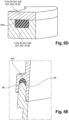
- the housing 2 of the air flow regulating device 1 comprises at least one sealing means 64 to prevent any air leakage outside the flow duct 4.
- the sealing means 64 ensure that the entire air flow passing through the air inlet 20 of the flow duct 4 exits through the air outlet 22 of the flow duct 4.
- the sealing means 64 may be arranged at different locations of the regulating device 1. Indeed, each sealing means 64 is arranged at the interface of, that is to say between, two elements of the regulating device 1 that are disjointed, in other words, dissociable or not forming continuity of material. More precisely, in order to achieve optimum sealing, the sealing means 64 is arranged on the peripheral periphery of each element forming a portion of the dissociated flow duct 4. In other words, between two elements forming a part of the flow duct 4, a sealing means 64 is arranged on the peripheral bonding surface at the peripheral edges of each of these elements.
- the sealing means 64 can therefore be arranged between each half-housing 2a 1 , 2a 2 and 2b 1 , 2b 2 and/or between a part 2a or 2b of the housing 2 and the supporting frame 62 and/or between each half-housing 2a 1 , 2a 2 and 2b 1 , 2b 2 and the supporting frame 62. It is also possible to envisage positioning a sealing means 64 between the housing 2 and the support frame 16 of the closing device 14 at the air inlet 20.
- the sealing means 64 may for example correspond to a seal, more precisely an O-ring 64c ( FIG.5C And FIG.5E ), to a 64a foam strip ( FIG.5A And FIG.5D ) or even to an overmolded elastomer lip 64b ( FIG.5B ).
- the sealing means 64 may be airtight or air and watertight.
- the subsequent description relating to the Figures 5A to 5E incorporates the concept of elements of the regulating device 1. It should be understood for the following that these elements correspond to two elements of the regulating device 1 which are separate, removable, separable, or assembled to each other by a reversible connection. These elements include the housing 2, each part 2a, 2b of the housing 2, each half-housing 2a 1 , 2a 2 , 2b 1 , 2b 2 , the support frame 16 of the shutter device 14 or the carrier frame 62 without any particular distinction or limitation.
- the sealing means 64 may correspond to a foam strip 64a arranged at the interface between two elements 2, 2a, 2b, 2a1, 2a2, 2b1, 2b2, 16, 62 of the regulating device.
- one of these elements say the first element, may comprise a groove 66 in which the foam strip 64b is arranged and the other element, say the second element, may comprise a protuberance 68 extending within the groove 66, that is to say in the direction of the bottom wall of the groove 66, and thus come to bear against the foam strip 64a, the foam strip 64a deforms so as to remain in contact with the protuberance 68 and the air flow can no longer pass through this cooperation.
- the foam strip 64a which may be a polyurethane foam, is particularly suitable for airtightness only.
- the foam strip 64a is arranged at the interface between two elements 2, 2a, 2b, 2a1, 2a2, 2b1, 2b2, 16, 62 of the regulating device 1 within a groove 66 present on the first element, and the second element comes directly into abutment against the foam strip 64a without protuberance, the foam strip 64a deforms so as to remain in contact with the second element 2, 2a, 2b, 2a1, 2a2, 2b1, 2b2, 16, 62 and the air flow can no longer pass through this cooperation.
- the sealing means 64 may correspond to an O-ring 64c arranged at the interface between two elements 2, 2a, 2b, 2a1, 2a2, 2b1, 2b2, 16, 62 of the regulating device 1.
- one of these elements say the first element, may comprise a groove 66 in which the O-ring 64c is arranged and the other element, say the second element, may come directly to bear against the O-ring 64c, the O-ring 64c deforms so as to remain in contact with the second element 2, 2a, 2b, 2a1, 2a2, 2b1, 2b2, 16, 62 and the air flow can no longer pass through this cooperation.
- the O-ring 64c which may be made of rubber or any other elastomer, is particularly suitable for air and water tightness.
- the second element can also include a protrusion 68 extending within the groove 66 and bearing against the O-ring 64c as illustrated in Figure 5E .
- the sealing means 64 may correspond to an overmolded lip 64b arranged at the interface between two elements 2, 2a, 2b, 2a1, 2a2, 2b1, 2b2, 16, 62 of the regulating device.
- one of these elements say the first element, may comprise a groove 66 and an overmolded lip 64b may be overmolded on the other element, say the second element, and come directly to bear against the bottom wall of the groove 66, that is to say against the first element, the overmolded lip 64b deforms so as to remain in contact with the first element 2, 2a, 2b, 2a1, 2a2, 2b1, 2b2, 16, 62 and the air flow can no longer pass through this cooperation.
- the overmolded lip 64b which may be made of rubber or any other elastomer (for example SEBS or polystyrene-b-poly(ethylene-butylene)-b-polystyrene), is particularly suitable for air and water sealing.
- SEBS polystyrene-b-poly(ethylene-butylene)-b-polystyrene
- the flow duct 4 comprises an air inlet 20 and an air outlet 22, the latter being composed of at least two separate ducts, the flap which will be described later being capable of closing each of said ducts.
- the air outlet 22 of the flow duct 4 comprises a clearing duct 24 arranged to guide the air flow towards the outside of the vehicle and a cooling duct 26 arranged to guide the air flow towards the engine compartment of the vehicle.
- the cooling duct 26 here corresponds to a duct where an opening 28 provided with a grid 30 is made within a wall of the housing 2 thus allowing the air flow to flow from the flow duct 4 towards the engine compartment.
- the cleaning duct 24 here corresponds to a duct where an opening 32 is made within a wall of the housing 2 thus allowing the air flow to flow from the flow duct 4 towards the outside of the vehicle.
- the device 1 for regulating an air flow comprises: further comprises a flap 34 arranged within the flow duct 4 downstream of the cooling unit 6 relative to the flow of the air flow.
- the flap 34 is of the drum type as illustrated in the figure 2 because, given that such a regulating device extends over a large part of the width of the vehicle (Y axis) and thus reaches more than one meter, the drum shutter, due to its structure which has better mechanical resistance, is better suited for such use.
- shutters may be envisaged such as a sliding shutter (also known as a sliding door) comprising a sliding door on which is arranged at least one rack and a gear complementary to the rack rotated about an axis by an actuator in order to set this shutter in motion, in particular according to a translational movement, according to an embodiment not illustrated.
- a sliding shutter also known as a sliding door
- a gear complementary to the rack rotated about an axis by an actuator in order to set this shutter in motion, in particular according to a translational movement, according to an embodiment not illustrated.
- the drum shutter 34 comprises a rotation axis 36 in the form of a shaft allowing the pivoting of the shutter 34.
- the drum shutter 34 further comprises three solid walls. Two side walls 38 arranged at the two opposite ends of the rotation axis 36, these two side walls 38 are parallel and are inscribed in a plane defined by the XZ axes perpendicular to the rotation axis 36, and a transverse wall 40 connecting the side walls to each other.
- the transverse wall 40 is inscribed in a plane defined by the XZ axes of curved shape allows the flow or drying up of the air flow in a duct 24, 26 of air outlet 22 of the flow duct 4 according to its positioning.
- the volume between the side walls 38, the transverse wall 40 and the axis of rotation 36 is unoccupied so that the air flow is able to pass between these elements as illustrated by the arrow F2 on the figure 2 .
- the transverse wall 40 of the drum shutter 34 is capable of closing the clearing duct 24 as illustrated in the figure 2
- the transverse wall 40 of the drum shutter 34 is also capable of closing the cooling duct 26 according to an embodiment not illustrated.
- the flap 34 match the shape of the walls of the housing 2 so as to ensure good sealing, the flap 34 may also further comprise elastomer lips 42 overmolded at the ends of the walls.
- the wall of the housing 2 where the cooling duct 26 is arranged is of substantially rounded shape, so that the curved transverse wall 40 of the flap 34 can completely close this outlet duct.
- the flap 34 When the vehicle is moving, the flap 34 is arranged to block the cooling duct 26, the air flow therefore passing through the cleaning duct 24. When the vehicle is parked at a terminal (the battery being recharged), the flap 34 is arranged to block the cleaning duct 24 cooling duct 26, the air flow therefore passing through the cooling duct 26 as illustrated in the figure. figure 2 .
- Shutter 34 is capable of adopting any intermediate position.
- the cooling unit 6 is inclined relative to the shutter device 14.
- the median planes of the cooling unit 6 and the shutter device 14 form an angle other than 0° (non-zero), in particular an angle comprised in a range between 10 and 80°, more precisely in a range between 30° and 60°.
- vanes 44 may prove advantageous for vanes 44 to be arranged upstream and/or downstream of the cooling unit 6 relative to the flow of the air flow.
- the vanes 44 correspond to air guides in the form of walls with rounded shapes defining corridors for the air flow in order to distribute the air flow F1 ( figure 2 ) over the entire surface of the heat exchangers 8, 10 of the unit cooling 6, this results in better thermal efficiency.
- the blades 44 may for example extend the continuity of the shutter flaps 18 of the shutter device 14 when they are in the opening configuration.
- the blades 44 may also have a general S shape with a leading edge corresponding to one end of the blade extending in a horizontal plane defined by the X and Y axes, a trailing edge substantially parallel to the leading edge but at a different height (Z) and an inclined section or ramp connecting the leading edge and the trailing edge which extends mainly along a vertical axis (Z).
- the invention is not limited to the shape of the blades 44 as long as they serve as a guide for the air flow, the blades 44 may for example be in the shape of a quarter circle.
- the first flat end portion of the blade 44 intended to be crossed by the air flow F1 corresponds to the leading edge and is flat.
- the second and last flat end portion intended to be crossed by the air flow F1 corresponds to the trailing edge and is also flat.
- the inclined section is not part of the leading and trailing edges.
- the passage section of the flow duct 4 increases from the air inlet 20 of the flow duct 4 to the cooling unit 6 and decreases from the cooling unit 6 to the air outlet 22 of the flow duct 4 according to the flow direction of the flow. air.
- the passage section of the flow duct 4 has at least one dimension (width and/or height) which increases as the length increases, or as one moves closer to the cooling unit 6 starting from the air inlet 20, depending on the direction of flow of the air flow.
- the passage section of the flow duct 4 has at least one dimension (width and/or height) which decreases as the length increases, or as one moves away from the cooling unit 6 as one moves closer to the air outlet 22, depending on the direction of flow of the air flow.
- sound-absorbing parts can be arranged within the housing 2, thus ensuring a sound-insulating coating of the flow duct 4 by eliminating or limiting the propagation of noise to the outside.
- the sound-absorbing part can for example correspond to a layer of polyurethane foam which has open or closed pores and preferably impregnated with a vinylidene copolymer, or to a cavity functioning as a Helmholtz resonator.
- the motor vehicle according to the invention therefore comprises an air intake provided with a grille and a device 1 for regulating this air intake.
- the air outlet 22 of the flow duct 4 comprises a clearing duct 24 arranged to lead the air flow towards the outside of the vehicle and a cooling duct 26 arranged to lead the air flow towards the engine compartment of the vehicle.
- the vehicle according to the invention may further comprise an additional inlet as well as an additional duct connecting said additional inlet with the cleaning duct leading the air flow towards the outside of the vehicle.
- This makes it possible to accentuate the venturi effect of the cleaning duct, thus increasing the flow rate of circulating air, thereby improving the thermal efficiency.
- the additional inlet may also be provided with a grid in order to prevent any foreign body (branches, leaves, etc.) from entering the additional duct.
Landscapes
- Engineering & Computer Science (AREA)
- Chemical & Material Sciences (AREA)
- Combustion & Propulsion (AREA)
- Transportation (AREA)
- Mechanical Engineering (AREA)
- Cooling, Air Intake And Gas Exhaust, And Fuel Tank Arrangements In Propulsion Units (AREA)
Claims (9)
- Vorrichtung zur Regelung (1) eines Luftstroms für einen Lufteinlass eines Kraftfahrzeugs, beinhaltend ein Gehäuse (2), das einen Strömungskanal (4) definiert, in dem ein Luftstrom strömt, in dem mindestens teilweise eine Kühleinheit (6) angeordnet ist, die mindestens einen Wärmetauscher (8, 10) und einen Motorlüfter (12) beinhaltet, wobei das Gehäuse (2) ein Dichtmittel (64, 64a, 64b, 64c) beinhaltet, um jegliche Luftleckage aus dem Strömungskanal (4) heraus zu verhindern,wobei die Kühleinheit (6) einen Tragrahmen (62) beinhaltet, in dem der mindestens eine Wärmetauscher (8; 10) und der Motorlüfter (2) angeordnet sind, wobei das Gehäuse (2) an dem Tragrahmen (62) befestigt ist, sodass der Tragrahmen (62) einem Teil des Strömungskanals (4) entspricht,dadurch gekennzeichnet, dassdas Gehäuse (2) einen ersten Teil (2a), der stromaufwärts des Tragrahmens (62) angeordnet ist und einen Lufteinlass (20) des Strömungskanals (4) mit dem Tragrahmen (62) verbindet, und einen zweiten Teil (2b), der stromabwärts des Tragrahmens (62) angeordnet ist, beinhaltet, wobei das Dichtmittel (64, 64a, 64b, 64c) zwischen dem Tragrahmen (62) und jedem Teil (2a, 2b) angeordnet ist, unddass der erste Teil (2a) aus zwei Gehäusehälften (2a1, 2a2) besteht, die zusammen den Strömungskanal (4) bilden, wobei das Dichtmittel (64, 64a, 64b, 64c) zwischen jeder Gehäusehälfte (2a1, 2a2) angeordnet ist.
- Regelungsvorrichtung (1) nach Anspruch 1, wobei das Dichtmittel (64, 64a, 64b, 64c) einem O-Ring (64c), einer aufgeformten Lippe (64b) oder einem Schaumstoffstreifen (64a) entspricht.
- Regelungsvorrichtung (1) nach einem der Ansprüche 1 oder 2, wobei das Dichtmittel luftdicht und/oder wasserdicht ist.
- Regelungsvorrichtung (1) nach einem der vorhergehenden Ansprüche, wobei der Strömungskanal (4) einen Lufteinlass (20) und einen Luftauslass (22) beinhaltet, wobei der Luftauslass (22) aus mindestens zwei unterschiedlichen Kanälen (24, 26) besteht, wobei die Vorrichtung mindestens eine Klappe (34) beinhaltet, die dazu fähig ist, jeden der Kanäle (24, 26) zu verschließen.
- Regelungsvorrichtung (1) nach einem der vorhergehenden Ansprüche, wobei eine Verschlussvorrichtung (14), die eine Anordnung von Verschlussklappen (18) beinhaltet, die dazu fähig sind, drehbar zu schwenken, um den Luftstromdurchsatz zu variieren, in dem Strömungskanal (4) mit Bezug auf die Strömung des Luftstroms stromaufwärts der Kühleinheit (6) angeordnet ist.
- Regelungsvorrichtung (1) nach Anspruch 5, wobei die Kühleinheit (6) mit Bezug auf die Verschlussvorrichtung (14) geneigt ist.
- Regelungsvorrichtung (1) nach einem der vorhergehenden Ansprüche, wobei das Gehäuse (2) oder jeder Teil des Gehäuses (2a, 2b) aus zwei Gehäusehälften (2a1, 2a2, 2b1, 2b2) besteht, die zusammen den Strömungskanal (4) bilden, wobei ein Dichtmittel (64, 64a, 64b, 64c) zwischen jeder Gehäusehälfte (2a1, 2a2, 2b1, 2b2) angeordnet ist.
- Regelungsvorrichtung (1) nach einem der vorhergehenden Ansprüche, wobei ein Dichtmittel (64, 64a, 64b, 64c) zwischen der Verschlussvorrichtung (14) und dem Gehäuse (2) angeordnet ist.
- Kraftfahrzeug, das einen Lufteinlass und eine Regelungsvorrichtung (1) für den Lufteinlass nach einem der Ansprüche 1 bis 9 beinhaltet.
Applications Claiming Priority (2)
| Application Number | Priority Date | Filing Date | Title |
|---|---|---|---|
| FR1858034A FR3085629B1 (fr) | 2018-09-07 | 2018-09-07 | Dispositif de regulation d'un flux d'air pour une entree d'air d'un vehicule automobile |
| PCT/FR2019/051924 WO2020049236A1 (fr) | 2018-09-07 | 2019-08-14 | Dispositif de regulation d'un flux d'air pour une entree d'air d'un vehicule automobile |
Publications (2)
| Publication Number | Publication Date |
|---|---|
| EP3847047A1 EP3847047A1 (de) | 2021-07-14 |
| EP3847047B1 true EP3847047B1 (de) | 2025-02-26 |
Family
ID=63963234
Family Applications (1)
| Application Number | Title | Priority Date | Filing Date |
|---|---|---|---|
| EP19769845.9A Active EP3847047B1 (de) | 2018-09-07 | 2019-08-14 | Vorrichtung zur regelung eines luftstroms für einen lufteinlass eines kraftfahrzeugs |
Country Status (6)
| Country | Link |
|---|---|
| US (1) | US11827090B2 (de) |
| EP (1) | EP3847047B1 (de) |
| JP (1) | JP2021536398A (de) |
| CN (1) | CN112654520A (de) |
| FR (1) | FR3085629B1 (de) |
| WO (1) | WO2020049236A1 (de) |
Families Citing this family (5)
| Publication number | Priority date | Publication date | Assignee | Title |
|---|---|---|---|---|
| MX2022006345A (es) * | 2019-11-26 | 2022-09-09 | Adval Tech Holding Ag | Obturador de radiador para vehiculos motorizados. |
| JP2021084518A (ja) * | 2019-11-27 | 2021-06-03 | ヤマハ発動機株式会社 | 車両 |
| FR3120021B1 (fr) * | 2021-02-23 | 2025-04-18 | Valeo Systemes Thermiques | Dispositif de régulation de flux d’air de face avant ayant une pluralité de cadres support |
| FR3126243B1 (fr) * | 2021-08-19 | 2023-07-07 | Psa Automobiles Sa | Système d’échange de chaleur à étanchéité par double chicane |
| JP7701580B1 (ja) * | 2025-02-06 | 2025-07-01 | 豊田鉄工株式会社 | 車両前部構造 |
Citations (1)
| Publication number | Priority date | Publication date | Assignee | Title |
|---|---|---|---|---|
| EP1216872B1 (de) * | 2000-12-22 | 2004-09-01 | FIAT AUTO S.p.A. | Kraftfahrzeug mit einer Anordnung zum Kapseln einer Wärmetauschereinheit im Motorraum |
Family Cites Families (27)
| Publication number | Priority date | Publication date | Assignee | Title |
|---|---|---|---|---|
| US4164262A (en) * | 1977-09-23 | 1979-08-14 | Hans List | Motor vehicle |
| JPH03130710U (de) * | 1990-04-17 | 1991-12-27 | ||
| US7022008B1 (en) * | 2005-01-06 | 2006-04-04 | Denso International America, Inc. | Air duct seal for HVAC case |
| DE102008020399A1 (de) * | 2008-04-24 | 2009-10-29 | Dr. Ing. H.C. F. Porsche Aktiengesellschaft | Kühleinrichtung |
| US20090302544A1 (en) * | 2008-06-05 | 2009-12-10 | Pugh Jr Charles A | Air Duct Sealing System |
| FR2950574B1 (fr) * | 2009-09-29 | 2012-03-23 | Valeo Systemes Thermiques | Bloc d'echange thermique pour vehicule automobile |
| CN102905923B (zh) * | 2010-05-21 | 2014-02-19 | 丰田自动车株式会社 | 冷却风导入构造 |
| CN102421620B (zh) * | 2010-06-03 | 2013-02-13 | 丰田自动车株式会社 | 冷却风导入结构 |
| DE102010017636A1 (de) * | 2010-06-29 | 2011-12-29 | Aksys Gmbh | Kühlluftführungssystem für ein Fahrzeug |
| WO2012017521A1 (ja) * | 2010-08-03 | 2012-02-09 | トヨタ自動車株式会社 | 車両用冷却構造 |
| US8479853B2 (en) * | 2011-05-17 | 2013-07-09 | GM Global Technology Operations LLC | Control of an airstream flow rate through a covered compartment by an adjustable shutter |
| US8892314B2 (en) * | 2011-06-15 | 2014-11-18 | GM Global Technology Operations LLC | Rejection of under-hood airflow |
| US20130081888A1 (en) * | 2011-09-30 | 2013-04-04 | GM Global Technology Operations LLC | Reconfigurable baseline opening for under-hood airflow |
| KR101418847B1 (ko) * | 2011-10-20 | 2014-07-11 | 한라비스테온공조 주식회사 | 차량용 공조장치 |
| FR2981887B1 (fr) | 2011-11-02 | 2015-04-17 | Renault Sas | Guide d'air structurel et modulaire a fonction de face avant technique de moteur de vehicule automobile et vehicule ainsi equipe. |
| US20140299396A1 (en) * | 2011-12-16 | 2014-10-09 | Toyota Jidosha Kabushiki Kaisha | Vehicle front portion structure |
| WO2013128618A1 (ja) * | 2012-03-01 | 2013-09-06 | トヨタ自動車株式会社 | 車両前部構造 |
| WO2013161010A1 (ja) * | 2012-04-24 | 2013-10-31 | トヨタ自動車株式会社 | 車両の冷却装置 |
| JP6201621B2 (ja) * | 2013-10-21 | 2017-09-27 | 株式会社デンソー | 車両用空調ユニット |
| FR3013302B1 (fr) * | 2013-11-19 | 2015-12-11 | Renault Sas | Guide d'air monopiece pour face avant de vehicule automobile et vehicule ainsi equipe |
| DE102014220119A1 (de) * | 2014-10-02 | 2016-04-07 | Röchling Automotive SE & Co. KG | Funktionsraum mit, vorzugsweise thermo-akustisch, isolierender Einfassung und mit dieser zusammenwirkender Luftklappenanordnung |
| JP6414344B2 (ja) * | 2015-12-02 | 2018-10-31 | 株式会社デンソー | 気流制御システム |
| US9744848B2 (en) * | 2015-12-21 | 2017-08-29 | Thunder Power New Energy Vehicle Development Company Limited | Vehicle radiator V type layout |
| FR3047204B1 (fr) * | 2016-02-03 | 2019-06-14 | Valeo Systemes Thermiques | Systeme de gestion d'entree d'air pour face avant de vehicule automobile |
| FR3050404B1 (fr) * | 2016-04-22 | 2019-08-02 | Compagnie Plastic Omnium | Dispositif d'ouverture et de fermeture de volets |
| CN105966231B (zh) | 2016-06-17 | 2019-08-09 | 郑州宇通客车股份有限公司 | 一种导风罩及安装该导风罩的车辆 |
| DE102016219485A1 (de) * | 2016-10-07 | 2018-04-12 | Audi Ag | Kraftfahrzeug und Energiespeichereinrichtung |
-
2018
- 2018-09-07 FR FR1858034A patent/FR3085629B1/fr active Active
-
2019
- 2019-08-14 EP EP19769845.9A patent/EP3847047B1/de active Active
- 2019-08-14 JP JP2021512800A patent/JP2021536398A/ja not_active Withdrawn
- 2019-08-14 CN CN201980058509.2A patent/CN112654520A/zh active Pending
- 2019-08-14 US US17/273,513 patent/US11827090B2/en active Active
- 2019-08-14 WO PCT/FR2019/051924 patent/WO2020049236A1/fr not_active Ceased
Patent Citations (1)
| Publication number | Priority date | Publication date | Assignee | Title |
|---|---|---|---|---|
| EP1216872B1 (de) * | 2000-12-22 | 2004-09-01 | FIAT AUTO S.p.A. | Kraftfahrzeug mit einer Anordnung zum Kapseln einer Wärmetauschereinheit im Motorraum |
Also Published As
| Publication number | Publication date |
|---|---|
| FR3085629A1 (fr) | 2020-03-13 |
| US20210339622A1 (en) | 2021-11-04 |
| US11827090B2 (en) | 2023-11-28 |
| CN112654520A (zh) | 2021-04-13 |
| EP3847047A1 (de) | 2021-07-14 |
| FR3085629B1 (fr) | 2021-01-01 |
| WO2020049236A1 (fr) | 2020-03-12 |
| JP2021536398A (ja) | 2021-12-27 |
Similar Documents
| Publication | Publication Date | Title |
|---|---|---|
| EP3847047B1 (de) | Vorrichtung zur regelung eines luftstroms für einen lufteinlass eines kraftfahrzeugs | |
| EP3774429B1 (de) | Luftströmungsregelungsvorrichtung für einen lufteinlass eines kraftfahrzeugs | |
| EP0856423B1 (de) | Luftklappe mit mehreren Klappteilen, insbesondere für ein Klimatisierungssystem für Kraftfahrzeuge | |
| EP3621840B1 (de) | Luftströmungsreguliereinrichtung für einen lufteinlass eines kraftfahrzeugs | |
| FR2925400A1 (fr) | Aerateur pour habitacle de vehicule automobile et tableau de bord equipe d'un tel aerateur | |
| EP1764245A1 (de) | Heizungs-, Lüftungs- und/oder Klimaanlage mit verbesserten akustischen Eigenschaften | |
| EP1595771A2 (de) | Absperrventil für den Wasserkasten eines Kraftfahrzeuges, und solch ein Wasserkasten | |
| EP1387774B1 (de) | Luftleitkasten | |
| EP3463959B1 (de) | Lager-verschlusselement für lufteinlassregelsystem und frontendmodul für kraftfahrzeug | |
| EP2154013B1 (de) | Heizungs-, Lüftungs- und/oder Klimaalage mit verbesserter Geräuschdämmung | |
| EP3411256B1 (de) | Verschlussvorrichtung für einen lufteinlass an der frontseite eines kraftfahrzeugs | |
| FR2920044A1 (fr) | Boitier constitutif d'une installation de ventilation, de chauffage et/ou de climatisation pourvu de moyens d'attenuation acoustique d'ondes sonores et installation comprenant un tel boitier | |
| EP1683949A1 (de) | Düse zur Kanalisation einer Luftströmung zu einem Wärmetauscher eines Kraftfahrzeuges und entsprechendes Fahrzeug | |
| WO2017103395A2 (fr) | Hélice pour un groupe moto-ventilateur d'un système de refroidissement d'un moteur de véhicule | |
| FR3071594B1 (fr) | Volet pour un dispositif de chauffage, ventilation et/ou climatisation d'un vehicule automobile | |
| WO2020260793A1 (fr) | Dispositif de regulation d'un flux d'air pour une entree d'air d'un vehicule automobile | |
| FR3134042A1 (fr) | Guide d’air pour dispositif de refroidissement de véhicule automobile | |
| EP1695848A1 (de) | Lufteinlassgehäuse für Fahrzeugklimaanlage | |
| FR3145703A1 (fr) | Calandre de véhicule automobile à entrée d’air modulable | |
| FR3097811A1 (fr) | Boîtier pour module de face avant d’un véhicule automobile | |
| FR2934969A1 (fr) | Appareil de chauffage, ventilation et/ou climatisation a acoustique amelioree | |
| FR3067401A1 (fr) | Systeme de ventilation pour vehicule automobile | |
| EP1044835A1 (de) | Heizungs- und/oder Klimaanlage eines Kraftfahrzeugs mit bewegbarer Klappe | |
| FR2921711A1 (fr) | Dispositif de connexion de l'entree/sortie d'un aerotherme d'un vehicule automobile et vehicule automobile comportant un tel dispositif |
Legal Events
| Date | Code | Title | Description |
|---|---|---|---|
| STAA | Information on the status of an ep patent application or granted ep patent |
Free format text: STATUS: UNKNOWN |
|
| STAA | Information on the status of an ep patent application or granted ep patent |
Free format text: STATUS: THE INTERNATIONAL PUBLICATION HAS BEEN MADE |
|
| PUAI | Public reference made under article 153(3) epc to a published international application that has entered the european phase |
Free format text: ORIGINAL CODE: 0009012 |
|
| STAA | Information on the status of an ep patent application or granted ep patent |
Free format text: STATUS: REQUEST FOR EXAMINATION WAS MADE |
|
| 17P | Request for examination filed |
Effective date: 20210317 |
|
| AK | Designated contracting states |
Kind code of ref document: A1 Designated state(s): AL AT BE BG CH CY CZ DE DK EE ES FI FR GB GR HR HU IE IS IT LI LT LU LV MC MK MT NL NO PL PT RO RS SE SI SK SM TR |
|
| DAV | Request for validation of the european patent (deleted) | ||
| DAX | Request for extension of the european patent (deleted) | ||
| STAA | Information on the status of an ep patent application or granted ep patent |
Free format text: STATUS: EXAMINATION IS IN PROGRESS |
|
| 17Q | First examination report despatched |
Effective date: 20220818 |
|
| P01 | Opt-out of the competence of the unified patent court (upc) registered |
Effective date: 20230528 |
|
| GRAP | Despatch of communication of intention to grant a patent |
Free format text: ORIGINAL CODE: EPIDOSNIGR1 |
|
| STAA | Information on the status of an ep patent application or granted ep patent |
Free format text: STATUS: GRANT OF PATENT IS INTENDED |
|
| INTG | Intention to grant announced |
Effective date: 20240924 |
|
| RAP3 | Party data changed (applicant data changed or rights of an application transferred) |
Owner name: VALEO SYSTEMES THERMIQUES |
|
| GRAS | Grant fee paid |
Free format text: ORIGINAL CODE: EPIDOSNIGR3 |
|
| GRAA | (expected) grant |
Free format text: ORIGINAL CODE: 0009210 |
|
| STAA | Information on the status of an ep patent application or granted ep patent |
Free format text: STATUS: THE PATENT HAS BEEN GRANTED |
|
| AK | Designated contracting states |
Kind code of ref document: B1 Designated state(s): AL AT BE BG CH CY CZ DE DK EE ES FI FR GB GR HR HU IE IS IT LI LT LU LV MC MK MT NL NO PL PT RO RS SE SI SK SM TR |
|
| REG | Reference to a national code |
Ref country code: GB Ref legal event code: FG4D Free format text: NOT ENGLISH |
|
| REG | Reference to a national code |
Ref country code: CH Ref legal event code: EP |
|
| REG | Reference to a national code |
Ref country code: DE Ref legal event code: R096 Ref document number: 602019066519 Country of ref document: DE |
|
| REG | Reference to a national code |
Ref country code: IE Ref legal event code: FG4D Free format text: LANGUAGE OF EP DOCUMENT: FRENCH |
|
| REG | Reference to a national code |
Ref country code: NL Ref legal event code: MP Effective date: 20250226 |
|
| PG25 | Lapsed in a contracting state [announced via postgrant information from national office to epo] |
Ref country code: RS Free format text: LAPSE BECAUSE OF FAILURE TO SUBMIT A TRANSLATION OF THE DESCRIPTION OR TO PAY THE FEE WITHIN THE PRESCRIBED TIME-LIMIT Effective date: 20250526 |
|
| PG25 | Lapsed in a contracting state [announced via postgrant information from national office to epo] |
Ref country code: FI Free format text: LAPSE BECAUSE OF FAILURE TO SUBMIT A TRANSLATION OF THE DESCRIPTION OR TO PAY THE FEE WITHIN THE PRESCRIBED TIME-LIMIT Effective date: 20250226 |
|
| PG25 | Lapsed in a contracting state [announced via postgrant information from national office to epo] |
Ref country code: PL Free format text: LAPSE BECAUSE OF FAILURE TO SUBMIT A TRANSLATION OF THE DESCRIPTION OR TO PAY THE FEE WITHIN THE PRESCRIBED TIME-LIMIT Effective date: 20250226 |
|
| PG25 | Lapsed in a contracting state [announced via postgrant information from national office to epo] |
Ref country code: ES Free format text: LAPSE BECAUSE OF FAILURE TO SUBMIT A TRANSLATION OF THE DESCRIPTION OR TO PAY THE FEE WITHIN THE PRESCRIBED TIME-LIMIT Effective date: 20250226 |
|
| REG | Reference to a national code |
Ref country code: LT Ref legal event code: MG9D |
|
| PG25 | Lapsed in a contracting state [announced via postgrant information from national office to epo] |
Ref country code: IS Free format text: LAPSE BECAUSE OF FAILURE TO SUBMIT A TRANSLATION OF THE DESCRIPTION OR TO PAY THE FEE WITHIN THE PRESCRIBED TIME-LIMIT Effective date: 20250626 Ref country code: NO Free format text: LAPSE BECAUSE OF FAILURE TO SUBMIT A TRANSLATION OF THE DESCRIPTION OR TO PAY THE FEE WITHIN THE PRESCRIBED TIME-LIMIT Effective date: 20250526 |
|
| PG25 | Lapsed in a contracting state [announced via postgrant information from national office to epo] |
Ref country code: NL Free format text: LAPSE BECAUSE OF FAILURE TO SUBMIT A TRANSLATION OF THE DESCRIPTION OR TO PAY THE FEE WITHIN THE PRESCRIBED TIME-LIMIT Effective date: 20250226 |
|
| PG25 | Lapsed in a contracting state [announced via postgrant information from national office to epo] |
Ref country code: HR Free format text: LAPSE BECAUSE OF FAILURE TO SUBMIT A TRANSLATION OF THE DESCRIPTION OR TO PAY THE FEE WITHIN THE PRESCRIBED TIME-LIMIT Effective date: 20250226 |
|
| PG25 | Lapsed in a contracting state [announced via postgrant information from national office to epo] |
Ref country code: PT Free format text: LAPSE BECAUSE OF FAILURE TO SUBMIT A TRANSLATION OF THE DESCRIPTION OR TO PAY THE FEE WITHIN THE PRESCRIBED TIME-LIMIT Effective date: 20250626 Ref country code: LV Free format text: LAPSE BECAUSE OF FAILURE TO SUBMIT A TRANSLATION OF THE DESCRIPTION OR TO PAY THE FEE WITHIN THE PRESCRIBED TIME-LIMIT Effective date: 20250226 |
|
| PG25 | Lapsed in a contracting state [announced via postgrant information from national office to epo] |
Ref country code: BG Free format text: LAPSE BECAUSE OF FAILURE TO SUBMIT A TRANSLATION OF THE DESCRIPTION OR TO PAY THE FEE WITHIN THE PRESCRIBED TIME-LIMIT Effective date: 20250226 Ref country code: GR Free format text: LAPSE BECAUSE OF FAILURE TO SUBMIT A TRANSLATION OF THE DESCRIPTION OR TO PAY THE FEE WITHIN THE PRESCRIBED TIME-LIMIT Effective date: 20250527 |
|
| REG | Reference to a national code |
Ref country code: AT Ref legal event code: MK05 Ref document number: 1770319 Country of ref document: AT Kind code of ref document: T Effective date: 20250226 |
|
| PG25 | Lapsed in a contracting state [announced via postgrant information from national office to epo] |
Ref country code: SE Free format text: LAPSE BECAUSE OF FAILURE TO SUBMIT A TRANSLATION OF THE DESCRIPTION OR TO PAY THE FEE WITHIN THE PRESCRIBED TIME-LIMIT Effective date: 20250226 |
|
| PG25 | Lapsed in a contracting state [announced via postgrant information from national office to epo] |
Ref country code: SM Free format text: LAPSE BECAUSE OF FAILURE TO SUBMIT A TRANSLATION OF THE DESCRIPTION OR TO PAY THE FEE WITHIN THE PRESCRIBED TIME-LIMIT Effective date: 20250226 |
|
| PG25 | Lapsed in a contracting state [announced via postgrant information from national office to epo] |
Ref country code: DK Free format text: LAPSE BECAUSE OF FAILURE TO SUBMIT A TRANSLATION OF THE DESCRIPTION OR TO PAY THE FEE WITHIN THE PRESCRIBED TIME-LIMIT Effective date: 20250226 |
|
| PGFP | Annual fee paid to national office [announced via postgrant information from national office to epo] |
Ref country code: DE Payment date: 20250812 Year of fee payment: 7 |
|
| PG25 | Lapsed in a contracting state [announced via postgrant information from national office to epo] |
Ref country code: IT Free format text: LAPSE BECAUSE OF FAILURE TO SUBMIT A TRANSLATION OF THE DESCRIPTION OR TO PAY THE FEE WITHIN THE PRESCRIBED TIME-LIMIT Effective date: 20250226 |
|
| PG25 | Lapsed in a contracting state [announced via postgrant information from national office to epo] |
Ref country code: AT Free format text: LAPSE BECAUSE OF FAILURE TO SUBMIT A TRANSLATION OF THE DESCRIPTION OR TO PAY THE FEE WITHIN THE PRESCRIBED TIME-LIMIT Effective date: 20250226 |
|
| PGFP | Annual fee paid to national office [announced via postgrant information from national office to epo] |
Ref country code: FR Payment date: 20250828 Year of fee payment: 7 |
|
| PG25 | Lapsed in a contracting state [announced via postgrant information from national office to epo] |
Ref country code: EE Free format text: LAPSE BECAUSE OF FAILURE TO SUBMIT A TRANSLATION OF THE DESCRIPTION OR TO PAY THE FEE WITHIN THE PRESCRIBED TIME-LIMIT Effective date: 20250226 Ref country code: CZ Free format text: LAPSE BECAUSE OF FAILURE TO SUBMIT A TRANSLATION OF THE DESCRIPTION OR TO PAY THE FEE WITHIN THE PRESCRIBED TIME-LIMIT Effective date: 20250226 |
|
| PG25 | Lapsed in a contracting state [announced via postgrant information from national office to epo] |
Ref country code: RO Free format text: LAPSE BECAUSE OF FAILURE TO SUBMIT A TRANSLATION OF THE DESCRIPTION OR TO PAY THE FEE WITHIN THE PRESCRIBED TIME-LIMIT Effective date: 20250226 |
|
| PG25 | Lapsed in a contracting state [announced via postgrant information from national office to epo] |
Ref country code: SK Free format text: LAPSE BECAUSE OF FAILURE TO SUBMIT A TRANSLATION OF THE DESCRIPTION OR TO PAY THE FEE WITHIN THE PRESCRIBED TIME-LIMIT Effective date: 20250226 |