EP3845788B1 - Staubdichtes schieberventil - Google Patents
Staubdichtes schieberventil Download PDFInfo
- Publication number
- EP3845788B1 EP3845788B1 EP20153017.7A EP20153017A EP3845788B1 EP 3845788 B1 EP3845788 B1 EP 3845788B1 EP 20153017 A EP20153017 A EP 20153017A EP 3845788 B1 EP3845788 B1 EP 3845788B1
- Authority
- EP
- European Patent Office
- Prior art keywords
- panel
- valve
- dust
- valve port
- slide
- Prior art date
- Legal status (The legal status is an assumption and is not a legal conclusion. Google has not performed a legal analysis and makes no representation as to the accuracy of the status listed.)
- Active
Links
Images

Classifications
-
- F—MECHANICAL ENGINEERING; LIGHTING; HEATING; WEAPONS; BLASTING
- F16—ENGINEERING ELEMENTS AND UNITS; GENERAL MEASURES FOR PRODUCING AND MAINTAINING EFFECTIVE FUNCTIONING OF MACHINES OR INSTALLATIONS; THERMAL INSULATION IN GENERAL
- F16K—VALVES; TAPS; COCKS; ACTUATING-FLOATS; DEVICES FOR VENTING OR AERATING
- F16K3/00—Gate valves or sliding valves, i.e. cut-off apparatus with closing members having a sliding movement along the seat for opening and closing
- F16K3/02—Gate valves or sliding valves, i.e. cut-off apparatus with closing members having a sliding movement along the seat for opening and closing with flat sealing faces; Packings therefor
- F16K3/0227—Packings
-
- F—MECHANICAL ENGINEERING; LIGHTING; HEATING; WEAPONS; BLASTING
- F16—ENGINEERING ELEMENTS AND UNITS; GENERAL MEASURES FOR PRODUCING AND MAINTAINING EFFECTIVE FUNCTIONING OF MACHINES OR INSTALLATIONS; THERMAL INSULATION IN GENERAL
- F16K—VALVES; TAPS; COCKS; ACTUATING-FLOATS; DEVICES FOR VENTING OR AERATING
- F16K3/00—Gate valves or sliding valves, i.e. cut-off apparatus with closing members having a sliding movement along the seat for opening and closing
- F16K3/30—Details
- F16K3/316—Guiding of the slide
- F16K3/3165—Guiding of the slide with rollers or balls
-
- F—MECHANICAL ENGINEERING; LIGHTING; HEATING; WEAPONS; BLASTING
- F16—ENGINEERING ELEMENTS AND UNITS; GENERAL MEASURES FOR PRODUCING AND MAINTAINING EFFECTIVE FUNCTIONING OF MACHINES OR INSTALLATIONS; THERMAL INSULATION IN GENERAL
- F16K—VALVES; TAPS; COCKS; ACTUATING-FLOATS; DEVICES FOR VENTING OR AERATING
- F16K3/00—Gate valves or sliding valves, i.e. cut-off apparatus with closing members having a sliding movement along the seat for opening and closing
- F16K3/02—Gate valves or sliding valves, i.e. cut-off apparatus with closing members having a sliding movement along the seat for opening and closing with flat sealing faces; Packings therefor
- F16K3/0218—Gate valves or sliding valves, i.e. cut-off apparatus with closing members having a sliding movement along the seat for opening and closing with flat sealing faces; Packings therefor with only one sealing face
-
- F—MECHANICAL ENGINEERING; LIGHTING; HEATING; WEAPONS; BLASTING
- F16—ENGINEERING ELEMENTS AND UNITS; GENERAL MEASURES FOR PRODUCING AND MAINTAINING EFFECTIVE FUNCTIONING OF MACHINES OR INSTALLATIONS; THERMAL INSULATION IN GENERAL
- F16K—VALVES; TAPS; COCKS; ACTUATING-FLOATS; DEVICES FOR VENTING OR AERATING
- F16K3/00—Gate valves or sliding valves, i.e. cut-off apparatus with closing members having a sliding movement along the seat for opening and closing
- F16K3/02—Gate valves or sliding valves, i.e. cut-off apparatus with closing members having a sliding movement along the seat for opening and closing with flat sealing faces; Packings therefor
- F16K3/0254—Gate valves or sliding valves, i.e. cut-off apparatus with closing members having a sliding movement along the seat for opening and closing with flat sealing faces; Packings therefor being operated by particular means
-
- F—MECHANICAL ENGINEERING; LIGHTING; HEATING; WEAPONS; BLASTING
- F16—ENGINEERING ELEMENTS AND UNITS; GENERAL MEASURES FOR PRODUCING AND MAINTAINING EFFECTIVE FUNCTIONING OF MACHINES OR INSTALLATIONS; THERMAL INSULATION IN GENERAL
- F16K—VALVES; TAPS; COCKS; ACTUATING-FLOATS; DEVICES FOR VENTING OR AERATING
- F16K3/00—Gate valves or sliding valves, i.e. cut-off apparatus with closing members having a sliding movement along the seat for opening and closing
- F16K3/02—Gate valves or sliding valves, i.e. cut-off apparatus with closing members having a sliding movement along the seat for opening and closing with flat sealing faces; Packings therefor
- F16K3/0281—Guillotine or blade-type valves, e.g. no passage through the valve member
-
- F—MECHANICAL ENGINEERING; LIGHTING; HEATING; WEAPONS; BLASTING
- F16—ENGINEERING ELEMENTS AND UNITS; GENERAL MEASURES FOR PRODUCING AND MAINTAINING EFFECTIVE FUNCTIONING OF MACHINES OR INSTALLATIONS; THERMAL INSULATION IN GENERAL
- F16K—VALVES; TAPS; COCKS; ACTUATING-FLOATS; DEVICES FOR VENTING OR AERATING
- F16K3/00—Gate valves or sliding valves, i.e. cut-off apparatus with closing members having a sliding movement along the seat for opening and closing
- F16K3/02—Gate valves or sliding valves, i.e. cut-off apparatus with closing members having a sliding movement along the seat for opening and closing with flat sealing faces; Packings therefor
- F16K3/16—Gate valves or sliding valves, i.e. cut-off apparatus with closing members having a sliding movement along the seat for opening and closing with flat sealing faces; Packings therefor with special arrangements for separating the sealing faces or for pressing them together
- F16K3/18—Gate valves or sliding valves, i.e. cut-off apparatus with closing members having a sliding movement along the seat for opening and closing with flat sealing faces; Packings therefor with special arrangements for separating the sealing faces or for pressing them together by movement of the closure members
- F16K3/184—Gate valves or sliding valves, i.e. cut-off apparatus with closing members having a sliding movement along the seat for opening and closing with flat sealing faces; Packings therefor with special arrangements for separating the sealing faces or for pressing them together by movement of the closure members by means of cams
-
- F—MECHANICAL ENGINEERING; LIGHTING; HEATING; WEAPONS; BLASTING
- F16—ENGINEERING ELEMENTS AND UNITS; GENERAL MEASURES FOR PRODUCING AND MAINTAINING EFFECTIVE FUNCTIONING OF MACHINES OR INSTALLATIONS; THERMAL INSULATION IN GENERAL
- F16K—VALVES; TAPS; COCKS; ACTUATING-FLOATS; DEVICES FOR VENTING OR AERATING
- F16K3/00—Gate valves or sliding valves, i.e. cut-off apparatus with closing members having a sliding movement along the seat for opening and closing
- F16K3/30—Details
- F16K3/314—Forms or constructions of slides; Attachment of the slide to the spindle
-
- F—MECHANICAL ENGINEERING; LIGHTING; HEATING; WEAPONS; BLASTING
- F16—ENGINEERING ELEMENTS AND UNITS; GENERAL MEASURES FOR PRODUCING AND MAINTAINING EFFECTIVE FUNCTIONING OF MACHINES OR INSTALLATIONS; THERMAL INSULATION IN GENERAL
- F16K—VALVES; TAPS; COCKS; ACTUATING-FLOATS; DEVICES FOR VENTING OR AERATING
- F16K31/00—Actuating devices; Operating means; Releasing devices
- F16K31/44—Mechanical actuating means
- F16K31/52—Mechanical actuating means with crank, eccentric, or cam
- F16K31/524—Mechanical actuating means with crank, eccentric, or cam with a cam
- F16K31/52475—Mechanical actuating means with crank, eccentric, or cam with a cam comprising a sliding valve
-
- F—MECHANICAL ENGINEERING; LIGHTING; HEATING; WEAPONS; BLASTING
- F16—ENGINEERING ELEMENTS AND UNITS; GENERAL MEASURES FOR PRODUCING AND MAINTAINING EFFECTIVE FUNCTIONING OF MACHINES OR INSTALLATIONS; THERMAL INSULATION IN GENERAL
- F16K—VALVES; TAPS; COCKS; ACTUATING-FLOATS; DEVICES FOR VENTING OR AERATING
- F16K31/00—Actuating devices; Operating means; Releasing devices
- F16K31/44—Mechanical actuating means
- F16K31/52—Mechanical actuating means with crank, eccentric, or cam
- F16K31/528—Mechanical actuating means with crank, eccentric, or cam with pin and slot
- F16K31/5286—Mechanical actuating means with crank, eccentric, or cam with pin and slot comprising a sliding valve
-
- F—MECHANICAL ENGINEERING; LIGHTING; HEATING; WEAPONS; BLASTING
- F16—ENGINEERING ELEMENTS AND UNITS; GENERAL MEASURES FOR PRODUCING AND MAINTAINING EFFECTIVE FUNCTIONING OF MACHINES OR INSTALLATIONS; THERMAL INSULATION IN GENERAL
- F16K—VALVES; TAPS; COCKS; ACTUATING-FLOATS; DEVICES FOR VENTING OR AERATING
- F16K31/00—Actuating devices; Operating means; Releasing devices
- F16K31/44—Mechanical actuating means
- F16K31/60—Handles
- F16K31/602—Pivoting levers, e.g. single-sided
Definitions
- the present invention relates to gate valve technology and more particularly, to a dustproof gate valve.
- Taiwan Patent 1551798 equivalent to US 9,464,721 , discloses a gate valve with a locking function. This design mainly uses a driver to drive a swing arm, thereby moving a slide. When the slide is moved to the second locking position, the valve member at the slide blocks the valve port, thereby achieving the effect of locking the valve member when the gage valve is closed.
- US2016245412 A1 discloses a gate valve with secure sealing mechanism including a main body having a valve opening, a driver disposed on the main body, a sliding seat slidingly disposed in the main body, a swing arm, and a valve member.
- two ends of the swing arm are connected to the driver and the sliding seat, respectively, whereby the driver drives the swing arm to move circularly between a first and second position, thereby triggering the sliding seat to slide.
- the swing arm is biased against the route direction of the sliding seat.
- the valve member is disposed on the sliding seat for moving in parallel or vertical to the valve opening, to prevent the sliding seat from swaying when the swing arm is at the first or second locking position.
- the present invention has been accomplished under the circumstances in view. It is the main object of the present invention to provide a dustproof gate valve, which completely closes the valve port when it is closed, and uses a dust pipe to shield the gap between the valve port and the housing of the gage valve when it is opened, thereby prohibiting dust from entering the inside of the gate valve.
- a dustproof gate valve comprises a housing, a slide, a driver, a swing arm, and a dust pipe.
- the housing is flat-shaped, comprising a first panel, a second panel, an accommodation space defined between the first panel and the second panel, and a guide rail set disposed inside the housing.
- the first panel and the second panel each have a valve port disposed opposite to each other.
- the guide rail set is substantially linear and has a curved portion at one end thereof.
- the slide comprises a body, and a valve member located on the body. The body is movably mounted in the housing, providing a driving chute.
- the valve member is movably mounted on the body, comprising a pulley set that is slidably mounted on the guide rail set inside the housing.
- the slide is drivable to move between a first position and a second position by the assembly relationship between the pulley set and the guide rail set.
- the pulley set enters the curved portion to move the valve member to the first panel in a linear extending direction perpendicular to the guide rail set and to close the valve port of the first panel when the slide is at the first position.
- the swing arm has one end thereof connected to the driver, and an opposite end thereof provided with a sliding block that is disposed in the driving chute.
- the driver is mounted in the housing. The driver is operable to drive the other end of the swing arm for circular motion.
- the sliding block is movable along the driving chute to act on the chute wall of the driving chute, thereby driving the slide to move.
- the dust pipe is mounted in the body and disposed between the valve port of the first panel and the valve port of the second panel to spatially connect the valve port of the first panel and the valve port of the second panel to the dust pipe when the slide is at the second position, and the pipe wall of the dust pipe is located at the edges of the valve ports of the first panel and the second panel to separate the valve port of the first panel and the valve port of the second panel from the accommodation space.
- the dust pipe is mounted on said body by a dust frame.
- the dust frame comprises two extension arms extending in direction away from said body and respectively disposed at two opposite sides relative to said dust pipe. Each extension arm has a roller located at a distal end thereof. The rollers of the two extension arms are stopped against a panel surface of said first panel when the slide is at said first position.
- the present invention can completely close the valve port of the first panel when the dustproof gate valve is closed, and the gap between the two valve ports and the housing can be shielded by the dust pipe when the dustproof gate valve is opened. By blocking the dust and making it difficult to enter the inside of the dustproof gate valve.
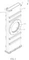
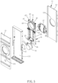
- a dustproof gate valve 10 in accordance with the present invention mainly comprises a housing 11, a slide 21, a driver 31, a swing arm 35 and a dust pipe 41.
- the housing 11 is flat, comprising a first panel 13, a second panel 15, and an accommodation space 111 defined between the first panel 13 and the second panel 15.
- the first panel 13 and the second panel 15 each have a valve port 131,151 cut therethrough and disposed opposite to each other.
- the housing 11 is internally provided with a guide rail set 12, which is substantially linear but has a curved portion 121 at one end.
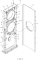
- the slide 21 comprises a body 22 and a valve member 27.
- the body 22 is movably mounted in the housing 11 and has a driving chute 23.
- the valve member 27 is movably mounted in the body 22 and provided with a pulley set 28.
- the pulley set 28 is slidably mounted on the guide rail set 12 inside the housing 11.
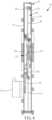
- the slide 21 is driven to move between a first position P1 and a second position P2 by the assembly relationship of the pully set 28 and the guide rail set 12.
- the pull set 28 enters the curved portion 121 and drives the valve member 27 to move to the first panel 13 in a straight line extending perpendicular to the guide rail set 12 and closes the valve port 131 of the first panel 13.
- the driver 31 is mounted to the housing 11.
- the driver 31 is a handle, and can be manually operated to rotate.
- a pneumatic device such as a pneumatic cylinder or an electric device such as a motor can be used as the driver.
- the swing arm 35 has one end thereof connected to the driver 31, and an opposite end thereof provided with a sliding block 36 that is disposed in the driving chute 23.
- the driver 31 is operated to drive the other end of the swing arm 35 for circular motion, and the sliding block 36 moves along the driving chute 23 to act on the chute wall of the driving chute 23, thereby driving the slide 21 to move.
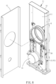
- the dust pipe 41 is mounted on the body 22.
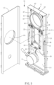
- the dust pipe 41 corresponds to the valve port 131 of the first panel 13 and the valve port 151 of the second panel 15 so that the valve port 131 of the first panel 13 and the valve port 151 of the second panel 15 are spatially connected to the dust pipe 41, and the pipe wall of the dust pipe 41 is located at the edges of the valve ports 131, 151 of the first panel 13 and the second panel 15 to separate the valve port 131 of the first panel 13 and the valve port 151 of the second panel 15 from the accommodation space 111.
- both ends of the dust pipe 41 are separated from the first panel 13 and the second panel 15 by a predetermined distance, leaving a gap S.
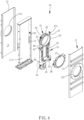
- the dust pipe 41 is provided on the body 22 through a dust frame 45.
- the dust pipe 41 has a mounting groove 42 located on an outer wall thereof.
- the dust frame 45 has a flange 46.
- the dust pipe 41 is coupled to the flange 46 with its mounting groove 42.
- the dust frame 45 has two extension arms 47 extending in direction away from the body 22.
- the two extension arms 47 are located on two opposite sides of the dust pipe 41, each having a distal end provided with a roller 471.
- the rollers 471 of the two extension arms 47 are stopped at the panel surface of the first panel 13.
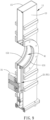
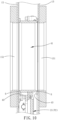
- the dust pipe 41 has a ring shape, as shown in FIGS.
- both ends of the dust pipe 41 face the first panel 13 and the second panel 15, and the end edges of the two ends of the dust pipe 41 extend radially outward to form a respective shoulder 43.
- This shoulder 43 can increase the depth of the gap S between the two valve ports 131,151 and the dust pipe 41, making it more difficult for dust to enter the housing 11 from the gap S.
- the arrangement of this shoulder 43 can be decided according to the needs. Whether the dust pipe 41 is set without the shoulder 43 can also achieve the effect of dust prevention. The dust pipe 41 can achieve the same dust-proof effect without the shoulder 43. Therefore, the shoulder 43 may not be provided.
- the dust pipe 41 may be forced by gravity to cause the two extension arms 47 to sag.
- the rollers 471 at the ends of the extension arms 47 can be stopped against the first panel 13, thereby ensuring that the dust frame 45 does not touch the first panel 13.
- the pipe wall of the dust pipe 41 is located on the edges of the valve ports 131, 151 of the first panel 13 and the second panel 15 to separate the valve ports 131, 151 of the first panel 13 and the second panel 15 from the accommodation space 111, the dust passing through the valve port 131 of the first panel 13, the dust pipe 41 and the valve port 151 of the second panel 15 is not easy to fall from the space between the first panel 13 and the second panel 15 into the housing 11, thereby achieving the effect of dust prevention.
- the gap S may allow dust to enter the housing 11, the amount of dust is very small compared to the conventional technology. In actual manufacturing, the gap S can be reduced by improving the assembly precision, thereby further reducing the amount of falling dust.
- the present invention can completely close the valve port 131 of the first panel 13 when the dustproof gate valve is closed, and the gap S between the two valve ports 131, 151 and the housing 11 can be shielded by the dust pipe 41 when the dustproof gate valve is opened.
- the present invention achieves the effect of dust prevention.
Landscapes
- Engineering & Computer Science (AREA)
- General Engineering & Computer Science (AREA)
- Mechanical Engineering (AREA)
- Details Of Valves (AREA)
- Sliding Valves (AREA)
Claims (4)
- Staubdichtes Absperrventil (10), welches umfasst:ein Gehäuse (11) in einer flachen Form, worin das Gehäuse (11) eine erste Platte (13), eine zweite Platte (15), einen Aufnahmeraum (111), der zwischen der ersten Platte (13) und der zweiten Platte (15) definiert ist, und einen Führungsschienensatz (12) aufweist, der innerhalb des Gehäuses (11) angeordnet ist, worin die erste Platte (13) und die zweite Platte (15) jeweils eine Ventilöffnung (131) (151) aufweisen, die einander abgewandt angeordnet sind, worin der Führungsschienensatz (12) im Wesentlichen linear ist und einen gekrümmten Abschnitt (121) an einem Ende davon aufweist;einen Schieber (21), der einen Körper (22) und ein Ventilelement (27) umfasst, das sich an dem Körper (22) befindet, worin der Körper (22) beweglich in dem Gehäuse (11) angebracht ist und eine Antriebsrinne (23) bereitstellt, worin das Ventilelement (27) beweglich an dem Körper (22) angebracht ist, worin das Ventilelement (27) einen Rollensatz (28) umfasst, worin der Rollensatz (28) an dem Führungsschienensatz (12) innerhalb des Gehäuses (11) gleitend angebracht ist, der Schieber (21) antreibbar ist, um sich zwischen einer ersten Position (P1) und einer zweiten Position (P2) durch die Aufbaubeziehung zwischen dem Rollensatz (28) und dem Führungsschienensatz (12) zu bewegen, worin der Rollensatz (28) in den gekrümmten Abschnitt (121) eintritt, um das Ventilelement (27) zu der ersten Platte (13) in einer sich linear erstreckenden Richtung senkrecht zu dem Führungsschienensatz (12) zu bewegen und die Ventilöffnung (131) der ersten Platte (13) zu schließen, wenn der Schieber (21) in der ersten Position (P1) ist;einen in dem Gehäuse (11) montierten Mitnehmer (31); undeinen Schwenkarm (35), dessen eines Ende mit dem Mitnehmer (31) verbunden ist und dessen gegenüberliegendes Ende mit einem Gleitblock (36) versehen ist, der in der Antriebsrinne (23) angeordnet ist, worin der Mitnehmer (31) betreibbar ist, um das andere Ende des Schwenkarms (35) für eine kreisförmige Bewegung anzutreiben, und worin der Gleitblock (36) entlang der Antriebsrutsche (23) bewegbar ist, um auf die Rinnenwand der Antriebsrinne (23) einzuwirken, wodurch der Schieber (21) zur Bewegung angetrieben wird;dadurch gekennzeichnet, dass das staubdichte Absperrventil (10) ferner umfasst:ein Staubrohr (41), das in dem Körper (22) angebracht ist, worin das Staubrohr (41) zwischen der Ventilöffnung (131) der ersten Platte (13) und der Ventilöffnung (151) der zweiten Platte (15) angeordnet ist, um die Ventilöffnung (131) der ersten Platte (13) und die Ventilöffnung (151) der zweiten Platte (15) räumlich mit dem Staubrohr (41) zu verbinden, wenn sich der Schieber (21) in der zweiten Position (P2) befindet, und die Rohrwand des Staubrohrs (41) an den Kanten der Ventilöffnungen (131) (151) der ersten Platte (13) und der zweiten Platte (15) angeordnet ist, um die Ventilöffnung (131) der ersten Platte (13) und die Ventilöffnung (151) der zweiten Platte (15) von dem Aufnahmeraum (111) zu trennen;worin das Staubrohr (41) an dem Körper (22) durch einen Staubrahmen (45) montiert ist;worin der Staubrahmen (45) zwei Verlängerungsarme (47) umfasst, die sich in Richtung weg von dem Körper (22) erstrecken und jeweils an zwei gegenüberliegenden Seiten relativ zu dem Staubrohr (41) angeordnet sind, worin jeder der Verlängerungsarme (47) eine Rolle (471) aufweist, die an einem distalen Ende davon angeordnet ist, worin die Rollen (471) der zwei Verlängerungsarme (47) gegen eine Plattenoberfläche der ersten Platte (13) angehalten werden, wenn der Schieber (21) in der ersten Position (P1) ist.
- Staubdichtes Absperrventil (10) nach Anspruch 1, worin das Staubrohr (41) eine Montagenut (42) aufweist und der Staubrahmen (45) einen Flansch (46) aufweist, der mit der Montagenut (42) des Staubrohrs (41) verbunden ist.
- Staubdichtes Absperrventil (10) nach Anspruch 1, worin die beiden abgewandten Enden des Staubrohrs (41) von der ersten Platte (13) und der zweiten Platte (15) um einen bestimmten Abstand getrennt sind, um einen Spalt (S) zu lassen, wenn sich der Schieber (21) in der zweiten Position (P2) befindet.
- Staubdichtes Absperrventil (10) nach Anspruch 1, worin sich die Endkanten der beiden abgewandten Enden des Staubrohrs (41) radial nach außen erstrecken, um eine entsprechende Schulter (43) auszubilden.
Applications Claiming Priority (1)
| Application Number | Priority Date | Filing Date | Title |
|---|---|---|---|
| TW109100075A TWI716250B (zh) | 2020-01-02 | 2020-01-02 | 具有防塵功能之閘閥 |
Publications (3)
| Publication Number | Publication Date |
|---|---|
| EP3845788A1 EP3845788A1 (de) | 2021-07-07 |
| EP3845788B1 true EP3845788B1 (de) | 2023-10-04 |
| EP3845788C0 EP3845788C0 (de) | 2023-10-04 |
Family
ID=69187595
Family Applications (1)
| Application Number | Title | Priority Date | Filing Date |
|---|---|---|---|
| EP20153017.7A Active EP3845788B1 (de) | 2020-01-02 | 2020-01-22 | Staubdichtes schieberventil |
Country Status (4)
| Country | Link |
|---|---|
| US (1) | US11112012B2 (de) |
| EP (1) | EP3845788B1 (de) |
| CN (2) | CN211924924U (de) |
| TW (1) | TWI716250B (de) |
Families Citing this family (3)
| Publication number | Priority date | Publication date | Assignee | Title |
|---|---|---|---|---|
| TWI716250B (zh) * | 2020-01-02 | 2021-01-11 | 新萊應材科技有限公司 | 具有防塵功能之閘閥 |
| CN117469414B (zh) * | 2023-12-27 | 2024-04-30 | 四川九天真空科技有限公司 | 一种侧驱插板阀及驱动系统 |
| US12510166B1 (en) * | 2024-10-04 | 2025-12-30 | Hui-Chuan Liao | Blast gate capable of preventing gate-dropping |
Family Cites Families (21)
| Publication number | Priority date | Publication date | Assignee | Title |
|---|---|---|---|---|
| US1844246A (en) * | 1929-12-11 | 1932-02-09 | Chapman Valve Mfg Co | Valve |
| US3610569A (en) * | 1969-10-02 | 1971-10-05 | Xomox Corp | Fluid control valve with retractable body seat |
| US4010928A (en) * | 1974-12-27 | 1977-03-08 | Xomox Corporation | Piston-operated parallel-slide gate valve |
| US4335733A (en) * | 1979-09-17 | 1982-06-22 | Richards John A | Valve for use in handling abrasive materials and method of wear prevention |
| CA1266199A (en) * | 1985-01-28 | 1990-02-27 | Waldemar H. Greiner | Damper construction |
| US4718637A (en) * | 1986-07-02 | 1988-01-12 | Mdc Vacuum Products Corporation | High vacuum gate valve having improved metal vacuum joint |
| JP2001165334A (ja) * | 1999-12-06 | 2001-06-22 | Smc Corp | スイングドアーゲートバルブ |
| JP3588637B2 (ja) * | 2001-03-28 | 2004-11-17 | 株式会社ブイテックス | 流量制御バルブ |
| US7611124B2 (en) * | 2004-12-22 | 2009-11-03 | Tokyo Electron Limited | Vacuum processing apparatus |
| DE102005043595A1 (de) * | 2005-09-12 | 2007-04-19 | Bösch, Hubert | Ventilmechanik für ein Vakuumventil |
| US9512927B2 (en) * | 2012-02-29 | 2016-12-06 | Fike Corporation | Pneumatic gate valve with integrated pressurized gas reservoir |
| JP6178845B2 (ja) * | 2013-04-22 | 2017-08-09 | Ckd株式会社 | ゲートバルブ |
| EP2949975B1 (de) * | 2014-05-22 | 2017-03-29 | Rico-Sicherheitstechnik AG | Explosionsschutzschieber zum Unterbrechen eines Fluidstroms in einer Rohrleitung |
| JP6160926B2 (ja) * | 2014-06-05 | 2017-07-12 | Smc株式会社 | ゲートバルブ |
| TWI580881B (zh) * | 2015-02-06 | 2017-05-01 | 新萊應材科技有限公司 | 具有鎖定功能之閘閥 |
| TWI551798B (zh) * | 2015-02-06 | 2016-10-01 | 新萊應材科技有限公司 | 具有鎖定功能之閘閥 |
| US9464721B2 (en) * | 2015-02-23 | 2016-10-11 | King Lai Hygienic Material Co., Ltd | Gate valve with secure sealing mechanism |
| CN207018556U (zh) * | 2017-07-04 | 2018-02-16 | 成都乘风阀门有限责任公司 | 可在线维护的上装平板闸阀 |
| CN207796110U (zh) * | 2018-01-04 | 2018-08-31 | 湖北津源阀门制造股份有限公司 | 一种烟气阀闸 |
| TWM595181U (zh) * | 2020-01-02 | 2020-05-11 | 新萊應材科技有限公司 | 具有防塵功能之閘閥 |
| TWI716250B (zh) * | 2020-01-02 | 2021-01-11 | 新萊應材科技有限公司 | 具有防塵功能之閘閥 |
-
2020
- 2020-01-02 TW TW109100075A patent/TWI716250B/zh active
- 2020-01-19 CN CN202020121764.7U patent/CN211924924U/zh not_active Withdrawn - After Issue
- 2020-01-19 CN CN202010069958.1A patent/CN113062991B/zh active Active
- 2020-01-22 EP EP20153017.7A patent/EP3845788B1/de active Active
- 2020-01-30 US US16/776,568 patent/US11112012B2/en active Active
Also Published As
| Publication number | Publication date |
|---|---|
| TWI716250B (zh) | 2021-01-11 |
| CN113062991A (zh) | 2021-07-02 |
| US20210207719A1 (en) | 2021-07-08 |
| TW202126935A (zh) | 2021-07-16 |
| CN113062991B (zh) | 2022-12-06 |
| CN211924924U (zh) | 2020-11-13 |
| EP3845788C0 (de) | 2023-10-04 |
| US11112012B2 (en) | 2021-09-07 |
| EP3845788A1 (de) | 2021-07-07 |
Similar Documents
| Publication | Publication Date | Title |
|---|---|---|
| EP3845788B1 (de) | Staubdichtes schieberventil | |
| WO2017101781A1 (zh) | 面板组件及空调器 | |
| WO2006004967A3 (en) | Door operator | |
| US9003708B2 (en) | Moving body drive apparatus | |
| US20240247532A1 (en) | Door hinge device for vehicle | |
| TWM595181U (zh) | 具有防塵功能之閘閥 | |
| MX2021015086A (es) | Sistema de operador de puerta. | |
| CN119894700A (zh) | 车门组件 | |
| KR101114807B1 (ko) | 기재를 진공실내로 유입하는 로드-락 장치 | |
| JP6195588B2 (ja) | ホーム柵 | |
| CN106288281B (zh) | 空调器风口组件及具有其的空调器 | |
| CN119314895B (zh) | 半导体工艺设备的装卸载腔室及半导体工艺设备 | |
| US9822575B2 (en) | Movable body driving device | |
| WO2003099697A1 (en) | Drive device for circular elevator door | |
| EP4001573A1 (de) | Drehschwenktür | |
| CN215967428U (zh) | 一种进料天窗装置及其加工设备 | |
| CN215761149U (zh) | 真空室 | |
| CN212318821U (zh) | 一种开度可调的档板阀 | |
| CN108188575B (zh) | 一种全封闭式贵金属切割机 | |
| CN115111388A (zh) | 带晃动防止机构的闸阀 | |
| KR100828419B1 (ko) | 자동차의 주유구용 커버 록킹장치 | |
| CN220539521U (zh) | 自动舱门、箱体及生物芯片处理装置 | |
| CN116856828B (zh) | 一种屏蔽门装置 | |
| KR100372693B1 (ko) | 차량용 윈도우 글라스 개폐 장치 | |
| CN114227628B (zh) | 一种箱体结构及工程机械 |
Legal Events
| Date | Code | Title | Description |
|---|---|---|---|
| STAA | Information on the status of an ep patent application or granted ep patent |
Free format text: STATUS: REQUEST FOR EXAMINATION WAS MADE |
|
| PUAI | Public reference made under article 153(3) epc to a published international application that has entered the european phase |
Free format text: ORIGINAL CODE: 0009012 |
|
| 17P | Request for examination filed |
Effective date: 20200122 |
|
| AK | Designated contracting states |
Kind code of ref document: A1 Designated state(s): AL AT BE BG CH CY CZ DE DK EE ES FI FR GB GR HR HU IE IS IT LI LT LU LV MC MK MT NL NO PL PT RO RS SE SI SK SM TR |
|
| GRAP | Despatch of communication of intention to grant a patent |
Free format text: ORIGINAL CODE: EPIDOSNIGR1 |
|
| STAA | Information on the status of an ep patent application or granted ep patent |
Free format text: STATUS: GRANT OF PATENT IS INTENDED |
|
| INTG | Intention to grant announced |
Effective date: 20230522 |
|
| RIN1 | Information on inventor provided before grant (corrected) |
Inventor name: HUANG, CHI-CHE Inventor name: LEE, CHUN-CHUN |
|
| GRAS | Grant fee paid |
Free format text: ORIGINAL CODE: EPIDOSNIGR3 |
|
| GRAA | (expected) grant |
Free format text: ORIGINAL CODE: 0009210 |
|
| STAA | Information on the status of an ep patent application or granted ep patent |
Free format text: STATUS: THE PATENT HAS BEEN GRANTED |
|
| AK | Designated contracting states |
Kind code of ref document: B1 Designated state(s): AL AT BE BG CH CY CZ DE DK EE ES FI FR GB GR HR HU IE IS IT LI LT LU LV MC MK MT NL NO PL PT RO RS SE SI SK SM TR |
|
| REG | Reference to a national code |
Ref country code: GB Ref legal event code: FG4D |
|
| REG | Reference to a national code |
Ref country code: CH Ref legal event code: EP |
|
| REG | Reference to a national code |
Ref country code: IE Ref legal event code: FG4D |
|
| REG | Reference to a national code |
Ref country code: DE Ref legal event code: R096 Ref document number: 602020018456 Country of ref document: DE |
|
| U01 | Request for unitary effect filed |
Effective date: 20231004 |
|
| U07 | Unitary effect registered |
Designated state(s): AT BE BG DE DK EE FI FR IT LT LU LV MT NL PT SE SI Effective date: 20231012 |
|
| U20 | Renewal fee for the european patent with unitary effect paid |
Year of fee payment: 5 Effective date: 20231228 |
|
| PG25 | Lapsed in a contracting state [announced via postgrant information from national office to epo] |
Ref country code: GR Free format text: LAPSE BECAUSE OF FAILURE TO SUBMIT A TRANSLATION OF THE DESCRIPTION OR TO PAY THE FEE WITHIN THE PRESCRIBED TIME-LIMIT Effective date: 20240105 |
|
| PG25 | Lapsed in a contracting state [announced via postgrant information from national office to epo] |
Ref country code: IS Free format text: LAPSE BECAUSE OF FAILURE TO SUBMIT A TRANSLATION OF THE DESCRIPTION OR TO PAY THE FEE WITHIN THE PRESCRIBED TIME-LIMIT Effective date: 20240204 |
|
| PG25 | Lapsed in a contracting state [announced via postgrant information from national office to epo] |
Ref country code: ES Free format text: LAPSE BECAUSE OF FAILURE TO SUBMIT A TRANSLATION OF THE DESCRIPTION OR TO PAY THE FEE WITHIN THE PRESCRIBED TIME-LIMIT Effective date: 20231004 |
|
| PG25 | Lapsed in a contracting state [announced via postgrant information from national office to epo] |
Ref country code: IS Free format text: LAPSE BECAUSE OF FAILURE TO SUBMIT A TRANSLATION OF THE DESCRIPTION OR TO PAY THE FEE WITHIN THE PRESCRIBED TIME-LIMIT Effective date: 20240204 Ref country code: GR Free format text: LAPSE BECAUSE OF FAILURE TO SUBMIT A TRANSLATION OF THE DESCRIPTION OR TO PAY THE FEE WITHIN THE PRESCRIBED TIME-LIMIT Effective date: 20240105 Ref country code: ES Free format text: LAPSE BECAUSE OF FAILURE TO SUBMIT A TRANSLATION OF THE DESCRIPTION OR TO PAY THE FEE WITHIN THE PRESCRIBED TIME-LIMIT Effective date: 20231004 |
|
| PG25 | Lapsed in a contracting state [announced via postgrant information from national office to epo] |
Ref country code: RS Free format text: LAPSE BECAUSE OF FAILURE TO SUBMIT A TRANSLATION OF THE DESCRIPTION OR TO PAY THE FEE WITHIN THE PRESCRIBED TIME-LIMIT Effective date: 20231004 Ref country code: PL Free format text: LAPSE BECAUSE OF FAILURE TO SUBMIT A TRANSLATION OF THE DESCRIPTION OR TO PAY THE FEE WITHIN THE PRESCRIBED TIME-LIMIT Effective date: 20231004 Ref country code: NO Free format text: LAPSE BECAUSE OF FAILURE TO SUBMIT A TRANSLATION OF THE DESCRIPTION OR TO PAY THE FEE WITHIN THE PRESCRIBED TIME-LIMIT Effective date: 20240104 Ref country code: HR Free format text: LAPSE BECAUSE OF FAILURE TO SUBMIT A TRANSLATION OF THE DESCRIPTION OR TO PAY THE FEE WITHIN THE PRESCRIBED TIME-LIMIT Effective date: 20231004 |
|
| REG | Reference to a national code |
Ref country code: DE Ref legal event code: R097 Ref document number: 602020018456 Country of ref document: DE |
|
| PG25 | Lapsed in a contracting state [announced via postgrant information from national office to epo] |
Ref country code: CZ Free format text: LAPSE BECAUSE OF FAILURE TO SUBMIT A TRANSLATION OF THE DESCRIPTION OR TO PAY THE FEE WITHIN THE PRESCRIBED TIME-LIMIT Effective date: 20231004 |
|
| PG25 | Lapsed in a contracting state [announced via postgrant information from national office to epo] |
Ref country code: SK Free format text: LAPSE BECAUSE OF FAILURE TO SUBMIT A TRANSLATION OF THE DESCRIPTION OR TO PAY THE FEE WITHIN THE PRESCRIBED TIME-LIMIT Effective date: 20231004 |
|
| PG25 | Lapsed in a contracting state [announced via postgrant information from national office to epo] |
Ref country code: SM Free format text: LAPSE BECAUSE OF FAILURE TO SUBMIT A TRANSLATION OF THE DESCRIPTION OR TO PAY THE FEE WITHIN THE PRESCRIBED TIME-LIMIT Effective date: 20231004 Ref country code: SK Free format text: LAPSE BECAUSE OF FAILURE TO SUBMIT A TRANSLATION OF THE DESCRIPTION OR TO PAY THE FEE WITHIN THE PRESCRIBED TIME-LIMIT Effective date: 20231004 Ref country code: RO Free format text: LAPSE BECAUSE OF FAILURE TO SUBMIT A TRANSLATION OF THE DESCRIPTION OR TO PAY THE FEE WITHIN THE PRESCRIBED TIME-LIMIT Effective date: 20231004 Ref country code: CZ Free format text: LAPSE BECAUSE OF FAILURE TO SUBMIT A TRANSLATION OF THE DESCRIPTION OR TO PAY THE FEE WITHIN THE PRESCRIBED TIME-LIMIT Effective date: 20231004 |
|
| PLBE | No opposition filed within time limit |
Free format text: ORIGINAL CODE: 0009261 |
|
| STAA | Information on the status of an ep patent application or granted ep patent |
Free format text: STATUS: NO OPPOSITION FILED WITHIN TIME LIMIT |
|
| PG25 | Lapsed in a contracting state [announced via postgrant information from national office to epo] |
Ref country code: MC Free format text: LAPSE BECAUSE OF FAILURE TO SUBMIT A TRANSLATION OF THE DESCRIPTION OR TO PAY THE FEE WITHIN THE PRESCRIBED TIME-LIMIT Effective date: 20231004 |
|
| PG25 | Lapsed in a contracting state [announced via postgrant information from national office to epo] |
Ref country code: MC Free format text: LAPSE BECAUSE OF FAILURE TO SUBMIT A TRANSLATION OF THE DESCRIPTION OR TO PAY THE FEE WITHIN THE PRESCRIBED TIME-LIMIT Effective date: 20231004 |
|
| REG | Reference to a national code |
Ref country code: CH Ref legal event code: PL |
|
| 26N | No opposition filed |
Effective date: 20240705 |
|
| PG25 | Lapsed in a contracting state [announced via postgrant information from national office to epo] |
Ref country code: CH Free format text: LAPSE BECAUSE OF NON-PAYMENT OF DUE FEES Effective date: 20240131 |
|
| PG25 | Lapsed in a contracting state [announced via postgrant information from national office to epo] |
Ref country code: CH Free format text: LAPSE BECAUSE OF NON-PAYMENT OF DUE FEES Effective date: 20240131 |
|
| PG25 | Lapsed in a contracting state [announced via postgrant information from national office to epo] |
Ref country code: IE Free format text: LAPSE BECAUSE OF NON-PAYMENT OF DUE FEES Effective date: 20240122 |
|
| PG25 | Lapsed in a contracting state [announced via postgrant information from national office to epo] |
Ref country code: IE Free format text: LAPSE BECAUSE OF NON-PAYMENT OF DUE FEES Effective date: 20240122 |
|
| U20 | Renewal fee for the european patent with unitary effect paid |
Year of fee payment: 6 Effective date: 20241231 |
|
| PGFP | Annual fee paid to national office [announced via postgrant information from national office to epo] |
Ref country code: GB Payment date: 20250123 Year of fee payment: 6 |
|
| PG25 | Lapsed in a contracting state [announced via postgrant information from national office to epo] |
Ref country code: CY Free format text: LAPSE BECAUSE OF FAILURE TO SUBMIT A TRANSLATION OF THE DESCRIPTION OR TO PAY THE FEE WITHIN THE PRESCRIBED TIME-LIMIT; INVALID AB INITIO Effective date: 20200122 |
|
| PG25 | Lapsed in a contracting state [announced via postgrant information from national office to epo] |
Ref country code: HU Free format text: LAPSE BECAUSE OF FAILURE TO SUBMIT A TRANSLATION OF THE DESCRIPTION OR TO PAY THE FEE WITHIN THE PRESCRIBED TIME-LIMIT; INVALID AB INITIO Effective date: 20200122 |
|
| PG25 | Lapsed in a contracting state [announced via postgrant information from national office to epo] |
Ref country code: TR Free format text: LAPSE BECAUSE OF FAILURE TO SUBMIT A TRANSLATION OF THE DESCRIPTION OR TO PAY THE FEE WITHIN THE PRESCRIBED TIME-LIMIT Effective date: 20231004 |