EP3842271B1 - Verriegelungsvorrichtung für kraftstofftankdeckel - Google Patents
Verriegelungsvorrichtung für kraftstofftankdeckel Download PDFInfo
- Publication number
- EP3842271B1 EP3842271B1 EP20216064.4A EP20216064A EP3842271B1 EP 3842271 B1 EP3842271 B1 EP 3842271B1 EP 20216064 A EP20216064 A EP 20216064A EP 3842271 B1 EP3842271 B1 EP 3842271B1
- Authority
- EP
- European Patent Office
- Prior art keywords
- unit
- fastening unit
- fastening
- lock
- fuel tank
- Prior art date
- Legal status (The legal status is an assumption and is not a legal conclusion. Google has not performed a legal analysis and makes no representation as to the accuracy of the status listed.)
- Active
Links
Images


Classifications
-
- B—PERFORMING OPERATIONS; TRANSPORTING
- B60—VEHICLES IN GENERAL
- B60K—ARRANGEMENT OR MOUNTING OF PROPULSION UNITS OR OF TRANSMISSIONS IN VEHICLES; ARRANGEMENT OR MOUNTING OF PLURAL DIVERSE PRIME-MOVERS IN VEHICLES; AUXILIARY DRIVES FOR VEHICLES; INSTRUMENTATION OR DASHBOARDS FOR VEHICLES; ARRANGEMENTS IN CONNECTION WITH COOLING, AIR INTAKE, GAS EXHAUST OR FUEL SUPPLY OF PROPULSION UNITS IN VEHICLES
- B60K15/00—Arrangement in connection with fuel supply of combustion engines or other fuel consuming energy converters, e.g. fuel cells; Mounting or construction of fuel tanks
- B60K15/03—Fuel tanks
- B60K15/04—Tank inlets
- B60K15/0406—Filler caps for fuel tanks
- B60K15/0409—Provided with a lock
-
- B—PERFORMING OPERATIONS; TRANSPORTING
- B60—VEHICLES IN GENERAL
- B60K—ARRANGEMENT OR MOUNTING OF PROPULSION UNITS OR OF TRANSMISSIONS IN VEHICLES; ARRANGEMENT OR MOUNTING OF PLURAL DIVERSE PRIME-MOVERS IN VEHICLES; AUXILIARY DRIVES FOR VEHICLES; INSTRUMENTATION OR DASHBOARDS FOR VEHICLES; ARRANGEMENTS IN CONNECTION WITH COOLING, AIR INTAKE, GAS EXHAUST OR FUEL SUPPLY OF PROPULSION UNITS IN VEHICLES
- B60K15/00—Arrangement in connection with fuel supply of combustion engines or other fuel consuming energy converters, e.g. fuel cells; Mounting or construction of fuel tanks
- B60K15/03—Fuel tanks
- B60K15/04—Tank inlets
- B60K15/05—Inlet covers
-
- B—PERFORMING OPERATIONS; TRANSPORTING
- B60—VEHICLES IN GENERAL
- B60K—ARRANGEMENT OR MOUNTING OF PROPULSION UNITS OR OF TRANSMISSIONS IN VEHICLES; ARRANGEMENT OR MOUNTING OF PLURAL DIVERSE PRIME-MOVERS IN VEHICLES; AUXILIARY DRIVES FOR VEHICLES; INSTRUMENTATION OR DASHBOARDS FOR VEHICLES; ARRANGEMENTS IN CONNECTION WITH COOLING, AIR INTAKE, GAS EXHAUST OR FUEL SUPPLY OF PROPULSION UNITS IN VEHICLES
- B60K15/00—Arrangement in connection with fuel supply of combustion engines or other fuel consuming energy converters, e.g. fuel cells; Mounting or construction of fuel tanks
- B60K15/03—Fuel tanks
- B60K15/04—Tank inlets
- B60K15/0406—Filler caps for fuel tanks
- B60K15/0409—Provided with a lock
- B60K2015/0416—Provided with a lock electrically actuated
-
- B—PERFORMING OPERATIONS; TRANSPORTING
- B60—VEHICLES IN GENERAL
- B60K—ARRANGEMENT OR MOUNTING OF PROPULSION UNITS OR OF TRANSMISSIONS IN VEHICLES; ARRANGEMENT OR MOUNTING OF PLURAL DIVERSE PRIME-MOVERS IN VEHICLES; AUXILIARY DRIVES FOR VEHICLES; INSTRUMENTATION OR DASHBOARDS FOR VEHICLES; ARRANGEMENTS IN CONNECTION WITH COOLING, AIR INTAKE, GAS EXHAUST OR FUEL SUPPLY OF PROPULSION UNITS IN VEHICLES
- B60K15/00—Arrangement in connection with fuel supply of combustion engines or other fuel consuming energy converters, e.g. fuel cells; Mounting or construction of fuel tanks
- B60K15/03—Fuel tanks
- B60K15/04—Tank inlets
- B60K15/0406—Filler caps for fuel tanks
- B60K2015/0432—Filler caps for fuel tanks having a specific connection between the cap and the vehicle or tank opening
- B60K2015/0445—Filler caps for fuel tanks having a specific connection between the cap and the vehicle or tank opening using hinges
-
- B—PERFORMING OPERATIONS; TRANSPORTING
- B60—VEHICLES IN GENERAL
- B60K—ARRANGEMENT OR MOUNTING OF PROPULSION UNITS OR OF TRANSMISSIONS IN VEHICLES; ARRANGEMENT OR MOUNTING OF PLURAL DIVERSE PRIME-MOVERS IN VEHICLES; AUXILIARY DRIVES FOR VEHICLES; INSTRUMENTATION OR DASHBOARDS FOR VEHICLES; ARRANGEMENTS IN CONNECTION WITH COOLING, AIR INTAKE, GAS EXHAUST OR FUEL SUPPLY OF PROPULSION UNITS IN VEHICLES
- B60K15/00—Arrangement in connection with fuel supply of combustion engines or other fuel consuming energy converters, e.g. fuel cells; Mounting or construction of fuel tanks
- B60K15/03—Fuel tanks
- B60K15/04—Tank inlets
- B60K15/0406—Filler caps for fuel tanks
- B60K2015/0451—Sealing means in the closure cap
-
- B—PERFORMING OPERATIONS; TRANSPORTING
- B60—VEHICLES IN GENERAL
- B60K—ARRANGEMENT OR MOUNTING OF PROPULSION UNITS OR OF TRANSMISSIONS IN VEHICLES; ARRANGEMENT OR MOUNTING OF PLURAL DIVERSE PRIME-MOVERS IN VEHICLES; AUXILIARY DRIVES FOR VEHICLES; INSTRUMENTATION OR DASHBOARDS FOR VEHICLES; ARRANGEMENTS IN CONNECTION WITH COOLING, AIR INTAKE, GAS EXHAUST OR FUEL SUPPLY OF PROPULSION UNITS IN VEHICLES
- B60K15/00—Arrangement in connection with fuel supply of combustion engines or other fuel consuming energy converters, e.g. fuel cells; Mounting or construction of fuel tanks
- B60K15/03—Fuel tanks
- B60K15/04—Tank inlets
- B60K15/0406—Filler caps for fuel tanks
- B60K2015/0454—Filler caps for fuel tanks combined closing of the fuel inlet and bodywork inlet by one element which is visible from outside
-
- B—PERFORMING OPERATIONS; TRANSPORTING
- B60—VEHICLES IN GENERAL
- B60K—ARRANGEMENT OR MOUNTING OF PROPULSION UNITS OR OF TRANSMISSIONS IN VEHICLES; ARRANGEMENT OR MOUNTING OF PLURAL DIVERSE PRIME-MOVERS IN VEHICLES; AUXILIARY DRIVES FOR VEHICLES; INSTRUMENTATION OR DASHBOARDS FOR VEHICLES; ARRANGEMENTS IN CONNECTION WITH COOLING, AIR INTAKE, GAS EXHAUST OR FUEL SUPPLY OF PROPULSION UNITS IN VEHICLES
- B60K15/00—Arrangement in connection with fuel supply of combustion engines or other fuel consuming energy converters, e.g. fuel cells; Mounting or construction of fuel tanks
- B60K15/03—Fuel tanks
- B60K15/04—Tank inlets
- B60K2015/0458—Details of the tank inlet
- B60K2015/0496—Details of the tank inlet the fuel inlet being arranged on the top of the fuel tank
-
- B—PERFORMING OPERATIONS; TRANSPORTING
- B60—VEHICLES IN GENERAL
- B60K—ARRANGEMENT OR MOUNTING OF PROPULSION UNITS OR OF TRANSMISSIONS IN VEHICLES; ARRANGEMENT OR MOUNTING OF PLURAL DIVERSE PRIME-MOVERS IN VEHICLES; AUXILIARY DRIVES FOR VEHICLES; INSTRUMENTATION OR DASHBOARDS FOR VEHICLES; ARRANGEMENTS IN CONNECTION WITH COOLING, AIR INTAKE, GAS EXHAUST OR FUEL SUPPLY OF PROPULSION UNITS IN VEHICLES
- B60K15/00—Arrangement in connection with fuel supply of combustion engines or other fuel consuming energy converters, e.g. fuel cells; Mounting or construction of fuel tanks
- B60K15/03—Fuel tanks
- B60K15/04—Tank inlets
- B60K15/05—Inlet covers
- B60K2015/0561—Locking means for the inlet cover
- B60K2015/0584—Locking means for the inlet cover the locking bolt is linearly moved to lock or unlock
-
- B—PERFORMING OPERATIONS; TRANSPORTING
- B60—VEHICLES IN GENERAL
- B60Y—INDEXING SCHEME RELATING TO ASPECTS CROSS-CUTTING VEHICLE TECHNOLOGY
- B60Y2200/00—Type of vehicle
- B60Y2200/10—Road Vehicles
- B60Y2200/12—Motorcycles, Trikes; Quads; Scooters
Definitions
- the present invention relates to a lock device of a fuel tank cap for locking or unlocking an opening and closing of a cap for blocking a fuel filler port connected to a fuel tank.
- a fuel filler port is provided at a top of a fuel tank in a large motorcycle
- a lock device for a fuel tank cap including a cap which can open and close the fuel filler port by moving between a closed position where the fuel filler port is blocked and an open position where the fuel filler port is open and a lock unit to lock or unlock the opening and closing of the cap has been proposed.
- a lock device for a fuel tank cap including a cap which can open and close the fuel filler port by moving between a closed position where the fuel filler port is blocked and an open position where the fuel filler port is open and a lock unit to lock or unlock the opening and closing of the cap
- a lock device including an operation knob which can swing around a swing shaft by an operator, a fastening unit which can be moved in conjunction with the swing operation of the operation knob and moves between a fastening position where a cap blocking a fuel filler port is held and an allowing position where the fastening is released and an opening movement of the cap is allowed, a lock unit which can lock movement of the fastening unit from the fastening position to the allowing position, or release the lock to allow movement of the fastening unit from the fastening position to the allowing position, and a detection switch which can detect the start of movement of the fastening unit accompanying an operation of an operating unit can be exemplified.
- JP 2017 196951 discloses a lock device of a fuel tank cap according to the preamble of claim 1.
- the invention is made in view of such circumstances and an obj ect thereof is to provide a lock device of a fuel tank cap which can secure a sufficient time from detection of the start of movement of a fastening unit by a detection switch until unlocking by a lock unit and can improve an operability by an operating unit.
- a lock device of a fuel tank cap as defined by the features of claim 1, including: a cap configured to open and close a fuel filler port by moving between a closed position where the fuel filler port leading to a fuel tank of a vehicle is blocked and an open position where the fuel filler port is open; an operating unit configured to be operated by an operator; a fastening unit movable in conjunction with an operation of the operating unit, the fastening unit configured to move between a fastening position where the cap blocking the fuel filler port is held and an allowing position where the fastening is released to allow the cap to open; a lock unit configured to lock movement of the fastening unit from the fastening position to the allowing position or release the lock to allow the movement of the fastening unit from the fastening position to the allowing position; and a detection switch configured to detect start of the movement of the fastening unit accompanying the operation of the operating unit, where: the lock device performs unlocking by the lock unit on condition that the detection switch
- a lock device of a fuel tank cap locks or unlocks an opening and closing of a cap for closing a fuel filler port connected to a fuel tank in a large two-wheeled vehicle.
- the lock device is configured to include a cap 1, an operation knob 2 (operating unit), a fastening unit 3, a solenoid 5 as lock unit, a slider 6, and a detection switch 8.
- the components described above are accommodated in a main body R fixed to a fuel tank T including a fuel filler port Ta.
- an annular cover portion H is fixed to an upper portion of the main body R by a plurality of bolts.
- the cap 1 can open or close the fuel filler port Ta by moving between a closed position (see Fig. 2A ) where the fuel filler port Ta connected to the fuel tank of a vehicle is closed and an open position (see Fig. 2B ) where the fuel filler port Ta is opened.
- the cap 1 is composed of an upper cap portion 1a and a lower cap portion 1b.
- an operator such as a driver picks the operation knob 2 by hand and pulls the operation knob 2 upward such that the cap 1 swings around a swing shaft La and moves from the closed position to the open position so that the fuel filler port Ta can face the outside.
- the upper cap portion 1a is formed with the swing shaft La which swings the cap 1 between the closed position and the open position at a predetermined position.
- the upper cap portion 1a holds the operation knob 2 (operating unit) to be swingable at the upper portion thereof.
- the lower cap portion 1b is attached with a sealing material S which seals the fuel filler port Ta when the cap 1 is in the closed position, and as illustrated in Fig. 4 to 6 , the lower cap portion 1b is configured to accommodate the fastening unit 3 in a movable state between a fastening position and an allowing position.
- the operation knob 2 (operating unit) has the swing shaft Lb integrally formed thereof. Protruding portions 2a are formed at both ends of the swing shaft Lb and are attached to recesses formed on an upper surface of the cap 1 (upper cap portion 1a). Then, when an operator pulls up and operates the operation knob 2, the operation knob 2 can be swung around the swing shaft Lb.
- the fastening unit 3 can be moved in conjunction with the operation of the operation knob 2 and the fastening unit 3 moves between a fastening position (see Fig. 4 ) where the cap 1 blocking the fuel filler port Ta is held and an allowing position (see Fig. 5 ) which releases the fastening and allows the opening movement of the cap 1. More specifically, the fastening unit 3 according to the embodiment is slidable substantially linearly in a working space (see Fig. 6 ) in the lower cap portion 1b.
- the fastening unit 3 is configured as follows. When the fastening unit 3 is in the fastening position, as illustrated in Fig.
- a fastening portion 3ba (the portion formed in a second fastening unit 3b described below) at the tip is fastened to a fastened portion Ha formed in the cover portion H to restrict the movement of the cap 1 from the closed position to the open position.
- the fastening portion 3ba is separated from the fastened portion Ha and the fastening is released, allowing the cap 1 to move from the closed position to the open position.
- the fastening unit 3 includes a first fastening unit 3a and the second fastening unit 3b, as illustrated in Figs. 10 to 12 .
- the first fastening unit 3a and the second fastening unit 3b consist of separate members.
- the first fastening unit 3a and the second fastening unit 3b can be moved integrally, or the first fastening unit 3a can be moved separately with respect to the second fastening unit 3b.
- the first fastening unit 3a and the second fastening unit 3b are urged from the allowing position toward the fastening position by urging forces of coil springs 9.
- the first fastening unit 3a moves by receiving the operating force of the operation knob 2 (operating unit) and the start of movement thereof can be detected by the detection switch 8.
- the first fastening unit 3a includes an abutment portion 3aa, an extension portion 3ab, an accommodation recess portion 3ac, a receiving portion 3ad, and an overload prevention portion 15.
- the abutment portion 3aa is composed of a portion formed at the tip portion of the first fastening unit 3a. As illustrated in Figs. 13 to 16 , depending on the movement of the first fastening unit 3a, the abutment portion 3aa can be brought into contact with or separated from the protruding portion 6a of the slider 6.
- the extension portion 3ab is composed of a portion formed at a base end portion of the first fastening unit 3a and is capable of abutting on one end of the coil spring 9 described above. As illustrated in Figs. 4 and 5 , the receiving portion 3ad located between the abutment portion 3aa and the extension portion 3ab is in contact with the protruding portion 2a of the operation knob 2. When the operation knob 2 swings around the swing shaft Lb, the receiving portion 3ad is pressed by the protruding portion 2a in response to the operating force, and the first fastening unit 3a can be moved.
- the accommodation recess portion 3ac has a concave shape capable of movably accommodating the overload prevention portion 15.
- the overload prevention unit 15 is for releasing load when a predetermined load or more is generated in the process of integrally moving the first fastening unit 3a and the second fastening unit 3b.
- the overload prevention portion 15 is composed of a separate member including a first abutment surface 15a and a spring receiving portion 15b. Then, as illustrated in Figs. 10 and 11 , the overload prevention portion 15 is accommodated in the accommodating recess 3ac via the coil spring 16.
- the first fastening unit 3a and the second fastening unit 3b are assembled so that the overload prevention portion 15 can slide in a notch portion 3be of the second fastening unit 3b.
- the second fastening unit 3b can be locked by the solenoid 5 (lock unit).
- the second fastening unit 3b is configured such that after the first fastening unit 3a moves by a predetermined dimension, the second fastening unit 3b moves integrally with the first fastening unit 3a so that the second fastening unit 3b can move from the fastening position to the allowing position.
- the second fastening unit 3b is configured to include a fastening portion 3ba, a tapered surface 3bb, an interfered portion 3bc, an extension portion 3bd, a notch portion 3be, and a second abutment surface 3bf.
- the fastening portion 3ba is composed of a portion which restricts the movement of the cap 1 from the closed position to the open position by fastening with respect to the fastened portion Ha and the tapered surface 3bb is formed on the back surface side thereof. Then, when the cap 1 is swung from the open position to the closed position, the tapered surface 3bb interferes with the fastened portion Ha of the cover portion H and the second fastening unit 3b moves slightly in a direction toward the allowing position against the urging force of the coil spring 9.
- the interfered portion 3bc is composed of a portion formed on the back surface of the second fastening unit 3b and the fastening unit 3 (second fastening unit 3b) can be locked by interfering with a plunger 5a of the solenoid 5.
- the extension portion 3bd is composed of a portion formed at the base end portion of the second fastening unit 3b and is capable of abutting on one end of the coil spring 9 described above.
- the notch portion 3be consists of a notch shape extending in a movement direction in the second fastening unit 3b and the overload prevention portion 15 is slidable on the notch portion 3be.
- the notch portion 3be has the second abutment surface 3bf which can abut on or be separated from the first abutment surface 15a of the overload prevention portion 15.
- the first fastening unit 3a and the second fastening unit 3b are assembled in parallel to the left and right and the overload prevention portion 15 of the first fastening unit 3a is assembled at the notch portion 3be of the second fastening unit 3b.
- the first abutment surface 15a of the first fastening unit 3a (overload prevention portion 15) and the second abutment surface 3bf of the second fastening unit 3b confront each other and a clearance having a predetermined dimension t is formed between the first abutment surface 15a and the second abutment surface 3bf.
- the lock unit are provided which can lock the movement from the fastening position to the allowing position of the fastening unit 3 or release the lock to allow the movement from the fastening position to the allowing position of the fastening unit 3.
- the lock unit according to the embodiment is composed of the solenoid 5 which can displace the plunger 5a by energization.
- the plunger 5a forms a lock member which can move between an interference position where the lock member interferes with and locks the interfered portion 3bc formed at a predetermined portion of the second fastening unit 3b and a non-interference position where the lock member does not interfere with the interfered portion 3bc and release the lock.
- the plunger 5a can be displaced between a protruding state and a contracted state by energization and is set to be an interference position in the protruding state and a non-interference position in the contracted state.
- the plunger 5a is constantly urged in a direction from the contracted state (non-interference position) to the protruding state (interference position) by a spring (not illustrated) formed inside the solenoid 5. That is, the plunger 5a is brought into a protruding state (interference position) by the urging force of the internal spring in a state where the plunger 5a is not energized and locks the fastening unit 3.
- the plunger 5a is put into a contracted state (non-interference position) against the urging force of the internal spring and unlocks the fastening unit 3.
- the plunger 5a at the interference position interferes and regulates and locks the movement toward the allowing position of the second fastening unit 3b.
- the plunger 5a moves from the interference position to the non-interference position and the lock is released, and thus the second fastening unit 3b is allowed to move toward the allowing position and the lock is released.
- the cap 1 can be swung to the open position.
- the solenoid 5 As illustrated in Figs. 20 to 24 , the solenoid 5 according to the embodiment is accommodated in a unit 4 fixed at a predetermined position in the main body R and the plunger 5a is in a state of protruding to the outside of the unit 4.
- the unit 4 includes a mounting case 10 to which the slider 6 and the detection switch 8 are mounted and the solenoid 5, the slider 6, and the detection switch 8 are integrated parts.
- the unit 4 is equipped with the slider 6 which works with the first fastening unit 3a and the detection switch 8 which can detect the movement of the slider 6.
- the unit 4 is configured such that the lock release by the solenoid 5 (lock unit) can be performed on condition that the detection switch 8 detects the movement of the slider 6.
- the slider 6 and the detection switch 8 are attached to the mounting case 10 forming the unit 4 and the protruding portion 6a of the slider 6 is in a state of protruding to the outside of the unit 4.
- the reference letter f indicates a sealing material for waterproofing.
- the slider 6 is in a state of being urged to the right side in Figs. 23 and 24 by the coil spring 7 attached to the mounting case 10 and the slider 6 is assembled in a state where the tip of the protruding portion 6a abuts on the abutment portion 3aa of the fastening unit 3.
- the slider 6 has a pressing surface 6b capable of pressing an operating portion 8a of the detection switch 8 at a portion different from the protruding portion 6a. It is configured such that, in response to the movement of the slider 6, the pressing surface 6b can press the operating portion 8a to electrically turn on the detection switch 8 (see Fig. 24 ) or the pressing surface 6b can be separated from the operating portion 8a so that the detection switch 8 can be electrically turned off (see Fig. 23 ).
- the slider 6 is in a state where the pressing surface 6b is separated from the operating portion 8a as illustrated in Fig. 23 and the detection switch 8 is electrically turned off.
- the operation knob 2 starts to be operated and the first fastening unit 3a starts moving
- the slider 6 moves in the same direction following the first fastening unit 3a by the urging force of the coil spring 7 and the pressing surface 6b presses the operating portion 8a and the detection switch 8 is electrically turned on.
- the detection switch 8 detects the movement of the slider 6 and is turned on electrically, the solenoid 5 is energized and the lock is released. Therefore, by continuing to operate the operation knob 2, the fastening unit 3 (second fastening unit 3b) is moved to the allowing position.
- the vehicle applied to the embodiment includes a transmission unit 11 which can be carried by a driver and transmits a vehicle-specific ID code on radio waves, a receiving unit 12 which is arranged on the vehicle side and capable of receiving the ID code from the transmission unit 11, and a determination unit 13 for determining whether the ID code received by the receiving unit 12 is legitimate in the vehicle.
- a control signal is transmitted to an ECU 14 to allow the engine to start, provided that the determination unit 13 determines that a legitimate ID code is received.
- the determination unit 13 is electrically connected to the detection switch 8. On condition that the determination unit 13 determines to have received a legitimate ID code and the detection switch 8 detects the start of movement of the first fastening unit 3a, the plunger 5a of the solenoid 5 is set to the non-interference position in the contracted state, and thus the lock is released. That is, when the determination unit 13 determines to have received the legitimate ID code, the detection switch 8 detects the start of movement of the first fastening unit 3a, and therefore, the lock unit performs unlocking by changing the plunger 5a of the solenoid 5 from the protruding state (interference position) to the contracted state (non-interference position).
- the determination unit 15 does not determine to have received a legitimate ID code, even if the detection switch 8 detects the start of movement of the first fastening unit 3a, the plunger 5a of the solenoid 5 is maintained in the protruding state (interference position) so that the unlocking operation by the lock unit is not performed.
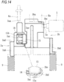
- the first fastening unit 3a moves downward in Fig. 13 , and the overload prevention portion 15 slides along an extension direction of the notch portion 3be. Therefore, the first fastening unit 3a moves relative to the second fastening unit 3b in the stopped state. Due to the movement of the first fastening unit 3a, as illustrated in Fig. 14 , the protruding portion 6a of the slider 6 follows the abutment portion 3aa and turns on the detection switch 8. As a result, the detection switch 8 can detect the start of movement of the first fastening unit 3a. Therefore, when the legitimate ID code is determined to be received by the determination unit 13, by energizing the solenoid 5, the plunger 5a can be moved from the interference position to the non-interference position to release the lock.
- the overload prevention portion 15 moves to the left side of the drawing against the urging force of the coil spring 16 to avoid abutment between the first abutment surface 15a and the second abutment surface 3bf.
- the first fastening unit 3a moves relative to the second fastening unit 3b and the stopped state of the second fastening unit 3b is maintained. Therefore, the operating force received in the first fastening unit 3a is not transmitted to the second fastening unit 3b.
- the lock device for the fuel tank cap locks or unlocks the opening and closing of a cap for blocking the fuel filler port connected to a fuel tank in a large two-wheeled vehicle, as in the first embodiment. Except for the fastening unit 3, the same components are configured as those in the first embodiment. The same components and parts as those in the first embodiment are designated by the same reference numerals and letters and detailed description thereof will be omitted.
- the fastening unit 3 is configured to include the first fastening unit 3a and the second fastening unit 3b.
- the first fastening unit 3a and second fastening unit 3b consist of separate members.
- the first fastening unit 3a and the second fastening unit 3b can be moved integrally, or the first fastening unit 3a can be moved separately against the second fastening unit 3b.
- the first fastening unit 3a and the second fastening unit 3b are urged from the allowing position toward the fastening position by the urging forces of the coil springs 9.
- the first fastening unit 3a moves by receiving the operating force of the operation knob 2 (operating unit) and the start of movement thereof can be detected by the detection switch 8. Therefore, as illustrated in Fig. 32 , the first fastening unit 3a includes the abutment portion 3aa, the extension portion 3ab, the receiving portion 3ad, and a first abutment surface 3ae.
- the first abutment surface 3ae consists of a surface of the protruding portion formed on a side of the first fastening unit 3a.
- the first fastening unit 3a and the second fastening unit 3b are assembled so that the protruding portion can slide in the notch portion 3be of the second fastening unit 3b.
- the first fastening unit 3a and the second fastening unit 3b are assembled in parallel on the left and right sides and the protruding portion where the first abutment surface 3ae is formed is located at the notch portion 3be of the second fastening unit 3b and is assembled.
- the first abutment surface 3ae of the first fastening unit 3a and the second abutment surface 3bf of the second fastening unit 3b confront each other and a clearance having a predetermined dimension t is formed between the first abutment surface 3ae and the second abutment surface 3bf.
- the first fastening unit 3a moves downward in Fig. 29 , and the protruding portion where the first abutment surface 3ae is formed slides along the extending direction of the notch portion 3be and the first fastening unit 3a moves relative to the second fastening unit 3b in the stopped state. Due to the movement of the first fastening unit 3a, as illustrated in Fig. 30 , the protruding portion 6a of the slider 6 follows the abutment portion 3aa and turns on the detection switch 8. As a result, the detection switch 8 can detect the start of movement of the first fastening unit 3a. Therefore, when the determination unit 13 determines that a legitimate ID code has been received, the plunger 5a can be moved from the interference position to the non-interference position and unlocked by energizing the solenoid 5.
- the fastening unit 3 includes the first fastening unit 3a which moves by receiving the operating force of the operation knob 2 (operating unit) and of which the start of movement can be detected by the detection switch 8 and the second fastening unit 3b which enables locking by the solenoid 5 (lock unit) and which is integrally moved with the first fastening unit 3a after the first fastening unit 3a is moved by the predetermined dimension t so that the second fastening unit 3b can be moved from the fastening position to the allowing position. Therefore, a sufficient time can be secured from the detection of the start of movement of the fastening unit 3 by the detection switch 8 until the unlocking by the solenoid 5, and thus the operability by the operation knob 2 can be improved.
- the first fastening unit 3a and the second fastening unit 3b can be moved integrally. Since a clearance of the predetermined dimension t is formed between the first abutment surface (15a, 3ae) and the second abutment surface 3bf, with a simple configuration, it is possible to secure a sufficient time from the detection of the movement start of the fastening unit 3 by the detection switch 8 until the unlocking by the solenoid 5.
- the first abutment surface 15a (or the second abutment surface 3bf) according to the first embodiment is formed in the overload prevention portion 15 for releasing a load when the load exceeding a predetermined value is generated in the process of integrally moving the first fastening unit 3a and the second fastening unit 3b. Therefore, it is possible to prevent the device from being damaged due to an overload generated in the operation process of the operation knob 2 (operating unit).
- Such an overload prevention portion 15 integrally moves the first fastening unit 3a and the second fastening unit 3b when a load exceeding a predetermined value does not occur in the operation process of the operation knob 2, and when a load exceeding a predetermined value is generated, the operating force received in the first fastening unit 3a is not transmitted to the second fastening unit 3b. As a result, it is possible to reliably release the overload generated in the operation process of the operation knob 2 and more reliably prevent damage to the device.
- the transmission unit 11 which can be carried by a driver and transmits a vehicle-specific ID code
- the receiving unit 12 which is arranged on the vehicle side and capable of receiving the ID code from the transmission unit 11, and the determination unit 13 for determining whether the ID code received by the receiving unit 12 is legitimate in the vehicle. Since the lock is released by the solenoid 5 (lock unit) on the condition that it is determined that a legitimate ID code has been received by the determination unit 13 and the start of the movement of the first fastening unit 3a is detected, the operability of the operation knob 2 can be improved while improving the crime prevention effect.
- the lock since unlocking by the lock unit is performed on the condition that a legitimate ID code is determined to be received by the determination unit 13 and the movement of the second fastening unit 3b is detected, the lock can be unlocked in the process of operating the operation knob 2.
- the operability can be improved as compared with a case in which the lock is released by a separate operating unit (access switch or the like) attached to the vehicle side.
- the lock unit is not limited to the solenoid 5 and may be another actuator or the like.
- the solenoid 5 as lock unit, the slider 6 and the detection switch 8 are integrated as a component with the unit 4, but the slider 6 and the detection switch 8 may be separately arranged without the unit 4.
- the movement of the fastening unit 3 is detected by the detection switch 8 via the slider 6, the movement of fastening unit 3 may be directly detected by the detection switch 8.
- the overload prevention unit 15 according to the first embodiment is accommodated in the accommodation recess portion 3ac while being urged by the coil spring 16.
- other configurations for example, one having different an urging unit from the coil spring 16 or one having a connecting force of the first fastening unit 3a and the second fastening unit 3b exclusively by frictional force
- the applicable vehicle may be an automobile, a motorcycle, a buggy, a snow vehicle, or the like.
- the fastening unit can be applied to a lock device of a fuel tank cap having a different appearance or having other functions added, as long as the lock device includes a first fastening unit which moves by receiving an operating force of an operating unit and of which the start of the movement can be detected by a detection switch and a second fastening unit which can be locked by a lock unit and is such that after the first fastening unit moves by a predetermined dimension, the second fastening unit moves integrally with the first fastening unit to move from the fastening position to the allowing position.
- a lock device of a fuel tank cap including: a cap configured to open and close a fuel filler port by moving between a closed position where the fuel filler port leading to a fuel tank of a vehicle is blocked and an open position where the fuel filler port is open; an operating unit configured to be operated by an operator; a fastening unit movable in conjunction with an operation of the operating unit, the fastening unit configured to move between a fastening position where the cap blocking the fuel filler port is held and an allowing position where the fastening is released to allow the cap to open; a lock unit configured to lock movement of the fastening unit from the fastening position to the allowing position or release the lock to allow the movement of the fastening unit from the fastening position to the allowing position; and a detection switch configured to detect start of the movement of the fastening unit accompanying the operation of the operating unit, where: the lock device performs unlocking by the lock unit on condition that the detection switch detects the start of the movement of
- the fastening unit includes the first fastening unit which moves by receiving the operating force of the operating unit and of which the start of movement can be detected by the detection switch and the second fastening unit which enables locking by the lock unit and which is integrally moved with the first fastening unit after the first fastening unit is moved by the predetermined dimension so that the second fastening unit can be moved from the fastening position to the allowing position. Therefore, a sufficient time can be secured from the detection of the start of movement of the fastening unit by the detection switch until the unlocking by the lock unit, and thus the operability by the operating unit can be improved.
- the first fastening unit and the second fastening unit may be configured to be moved integrally by making a first abutment surface formed in the first fastening unit abut on a second abutment surface formed in the second fastening unit and a clearance of a predetermined dimension is formed between the first abutment surface and the second abutment surface.
- the first fastening unit and the second fastening unit can be moved integrally. Since a clearance of the predetermined dimension is formed between the first abutment surface and the second abutment surface, with a simple configuration, it is possible to secure a sufficient time from the detection of the movement start of the fastening unit by the detection switch until the unlocking by the lock unit.
- the first abutment surface or the second abutment surface may be formed in an overload prevention portion for releasing a load when the load exceeding a predetermined value is generated in a process of integrally moving the first fastening unit and the second fastening unit.
- the first abutment surface or the second abutment surface is formed in the overload prevention portion for releasing a load when the load exceeding a predetermined value is generated in the process of integrally moving the first fastening unit and the second fastening unit. Therefore, it is possible to prevent a device from being damaged due to an overload generated in the operation process of the operating unit.
- the overload prevention portion may be configured such that the first fastening unit and the second fastening unit are integrally moved when the load exceeding the predetermined value does not occur in an operating process of the operating unit and an operating force received by the first fastening unit is not transmitted to the second fastening unit when the load exceeding the predetermined value is generated.
- the overload prevention portion integrally moves the first fastening unit and the second fastening unit when a load exceeding a predetermined value does not occur in the operation process of the operating unit, and when a load exceeding a predetermined value is generated, the operating force received in the first fastening unit is not transmitted to the second fastening unit.
- the overload prevention portion integrally moves the first fastening unit and the second fastening unit when a load exceeding a predetermined value does not occur in the operation process of the operating unit, and when a load exceeding a predetermined value is generated, the operating force received in the first fastening unit is not transmitted to the second fastening unit.
- the lock device may further include: a transmission unit that a driver can carry and transmit a vehicle-specific ID code; a receiving unit which is arranged on a vehicle side and is configured to receive the ID code from the transmission unit; and a determination unit to determine whether the ID code received by the receiving unit is legitimate in the vehicle, and the lock unit may release the lock on the condition that the legitimate ID code is determined to be received by the determination unit and the start of movement of the first fastening unit is detected.
- the lock device includes the transmission unit which can be carried by a driver and transmits a vehicle-specific ID code, the receiving unit which is arranged on the vehicle side and capable of receiving the ID code from the transmission unit, and the determination unit for determining whether the ID code received by the receiving unit is legitimate in the vehicle. Since the lock is released by the lock unit on the condition that it is determined that a legitimate ID code has been received by the determination unit and the start of the movement of the first fastening unit is detected. As a result, the operability of the operating unit can be improved while improving the crime prevention effect.
Landscapes
- Engineering & Computer Science (AREA)
- Life Sciences & Earth Sciences (AREA)
- Sustainable Development (AREA)
- Sustainable Energy (AREA)
- Chemical & Material Sciences (AREA)
- Combustion & Propulsion (AREA)
- Transportation (AREA)
- Mechanical Engineering (AREA)
- Lock And Its Accessories (AREA)
- Cooling, Air Intake And Gas Exhaust, And Fuel Tank Arrangements In Propulsion Units (AREA)
Claims (5)
- Verriegelungsvorrichtung eines Kraftstofftankdeckels, umfassend:eine Kappe (1) die so ausgeführt ist, dass sie einen Kraftstoffeinfüllkanal öffnet und schließt, indem sie sich zwischen einer geschlossenen Position, in der der zu einem Kraftstofftank eines Fahrzeugs führende Kraftstoffeinfüllkanal blockiert ist, und einer offenen Position bewegt, in der der Kraftstoffeinfüllkanal geöffnet ist;eine Betätigungs-Einheit, die zum Betätigen durch eine Bedienungsperson ausgeführt ist;eine Fixier-Einheit (3), die in Verbindung mit einer Betätigung der Betätigungs-Einheit bewegt werden kann, wobei die Fixier-Einheit so ausgeführt ist, dass sie sich zwischen einer Fixier-Position, in der die Kappe, die den Kraftstoffeinfüllkanal blockiert, gehalten wird, und einer Freigabe-Position bewegt, in der die Fixierung gelöst ist, so dass sich die Kappe öffnen kann;eine Arretier-Einheit, die so ausgeführt ist, dass sie Bewegung der Fixier-Einheit von der Fixier-Position an die Freigabe-Position arretiert oder die Arretierung löst, um die Bewegung der Fixier-Einheit von der Fixier-Position an die Freigabe-Position zu ermöglichen,dadurch gekennzeichnet, dass die Arretiervorrichtung umfasst:
einen Erfassungs-Schalter (8), der so ausgeführt ist, dass er Beginn der Bewegung der Fixier-Einheit erfasst, die mit der Betätigung der Betätigungs-Einheit einhergeht, wobei:die Arretiervorrichtung Entarretieren durch die Arretier-Einheit unter der Bedingung durchführt, dass der Erfassungs-Schalter den Beginn der Bewegung der Fixier-Einheit erfasst; unddie Fixier-Einheit (3) enthält:eine erste Fixier-Einheit (3a), die sich bewegt, wenn sie eine Betätigungskraft der Betätigungs-Einheit empfängt und für die der Beginn der Bewegung durch den Erfassungs-Schalter (8) erfasst werden kann; sowieeine zweite Fixier- Einheit (3b), die Arretieren durch die Arretier-Einheit ermöglicht und die integral mit der ersten Fixier-Einheit (3a) bewegt wird, nachdem die erste Fixier-Einheit (3a) um ein vorgegebenes Maß bewegt worden ist, so dass die zweite Fixier-Einheit (3b) von der Fixier-Position an die Freigabe-Position bewegt werden kann. - Verriegelungsvorrichtung des Kraftstofftankdeckels nach Anspruch 1, wobei
die erste Fixier-Einheit (3a) und die zweite Fixier-Einheit (3b) so ausgeführt sind, dass sie integral bewegt werden, indem eine erste Anliegefläche, die in der ersten Fixier-Einheit (3a) ausgebildet ist, zum Anliegen an einer zweiten Anliegefläche gebracht wird, die in der zweiten Fixier-Einheit (3b) ausgebildet ist, und ein Zwischenraum einer vorgegebenen Abmessung zwischen der ersten Anliegefläche und der zweiten Anliegefläche ausgebildet ist. - Verriegelungsvorrichtung des Kraftstofftankdeckels nach Anspruch 2, wobei
die erste Anliegefläche oder die zweite Anliegefläche in einem Abschnitt (15) zur Verhinderung von Überlastung ausgebildet ist, um eine Last abzubauen, wenn die einen vorgegebenen Wert überschreitende Last bei einem Vorgang zum integralen Bewegen der ersten Fixier-Einheit (3a) und der zweiten Fixier-Einheit (3b) erzeugt wird. - Verriegelungsvorrichtung des Kraftstofftankdeckels nach Anspruch 3, wobei
der Abschnitt (15) zur Verhinderung von Überlastung so ausgeführt ist, dass die erste Fixier-Einheit (3a) und die zweite Fixier-Einheit (3b) integral bewegt werden, wenn die den vorgegebenen Wert überschreitende Last bei einem Betätigungsvorgang der Betätigungs-Einheit nicht auftritt und eine durch die erste Fixier-Einheit (3a) empfangene Betätigungskraft nicht auf die zweite Fixier-Einheit (3b) übertragen wird, wenn die den vorgegebenen Wert überschreitende Last erzeugt wird. - Verriegelungsvorrichtung des Kraftstofftankdeckels (100) nach einem der Ansprüche 1 bis 4, die des Weiteren umfasst:eine Sende-Einheit (11), die ein Fahrer mitführen kann und die einen fahrzeugspezifischen ID-Code sendet;eine Empfangs-Einheit, die an einer Fahrzeugseite angeordnet und so ausgeführt ist, dass sie den ID-Code von der Sende-Einheit empfängt; sowieeine Feststellungs-Einheit (13), die feststellt, ob der durch die Empfangs-Einheit empfangene ID-Code für das Fahrzeug zulässig ist, wobeidie Arretier-Einheit die Arretierung unter der Bedingung löst, dass durch die Feststellungs-Einheit (13) festgestellt wird, dass der zulässige ID-Code empfangen wird, und der Beginn von Bewegung der ersten Fixier-Einheit (3a) erfasst wird.
Applications Claiming Priority (1)
| Application Number | Priority Date | Filing Date | Title |
|---|---|---|---|
| JP2019233857A JP7279895B2 (ja) | 2019-12-25 | 2019-12-25 | 燃料タンクキャップのロック装置 |
Publications (2)
| Publication Number | Publication Date |
|---|---|
| EP3842271A1 EP3842271A1 (de) | 2021-06-30 |
| EP3842271B1 true EP3842271B1 (de) | 2023-02-15 |
Family
ID=73856408
Family Applications (1)
| Application Number | Title | Priority Date | Filing Date |
|---|---|---|---|
| EP20216064.4A Active EP3842271B1 (de) | 2019-12-25 | 2020-12-21 | Verriegelungsvorrichtung für kraftstofftankdeckel |
Country Status (3)
| Country | Link |
|---|---|
| US (1) | US11325463B2 (de) |
| EP (1) | EP3842271B1 (de) |
| JP (1) | JP7279895B2 (de) |
Families Citing this family (3)
| Publication number | Priority date | Publication date | Assignee | Title |
|---|---|---|---|---|
| JP6964723B1 (ja) * | 2020-06-23 | 2021-11-10 | ヤマハ発動機株式会社 | 鞍乗型車両 |
| TWI873784B (zh) * | 2023-08-16 | 2025-02-21 | 東洋建蒼電機股份有限公司 | 油箱蓋構造 |
| CN119737088B (zh) * | 2025-03-04 | 2025-05-30 | 浙江雷牌机件有限公司 | 一种电动油箱锁 |
Family Cites Families (14)
| Publication number | Priority date | Publication date | Assignee | Title |
|---|---|---|---|---|
| US3915491A (en) * | 1974-06-21 | 1975-10-28 | Tom C Montgomery | Remote controlled gas tank lock |
| JPH0971275A (ja) | 1995-09-08 | 1997-03-18 | Honda Motor Co Ltd | 車両制御装置 |
| JP4346384B2 (ja) | 2003-09-03 | 2009-10-21 | 朝日電装株式会社 | 燃料タンクキャップのロック装置 |
| US7331616B2 (en) * | 2004-07-15 | 2008-02-19 | General Motors Corporation | Hood latch assemblies utilizing active materials and methods of use |
| DE102004035013B3 (de) * | 2004-07-20 | 2006-04-13 | Itw Automotive Products Gmbh & Co. Kg | Verriegelungssystem für eine Tankeinfüllmulde |
| IT1393382B1 (it) | 2008-12-18 | 2012-04-20 | Zadi S P A | Tappo per serbatoi, in particolare per motocicli. |
| CA2805662C (en) * | 2010-10-12 | 2014-04-22 | Kabushiki Kaisha Tokai Rika Denki Seisakusho | Device for detecting opening/closing of charger lid |
| JP5864242B2 (ja) | 2011-12-14 | 2016-02-17 | 株式会社東海理化電機製作所 | リッドロック制御装置 |
| JP6211909B2 (ja) * | 2013-12-02 | 2017-10-11 | 株式会社ニフコ | リッド装置 |
| JP6256683B2 (ja) | 2013-12-26 | 2018-01-10 | 三菱自動車工業株式会社 | フューエルフィラーリッド装置 |
| KR101567246B1 (ko) * | 2014-10-17 | 2015-11-06 | 현대자동차주식회사 | 액츄에이터 일체형 푸시 오프너 |
| DE102015001180A1 (de) * | 2015-01-30 | 2016-08-04 | Hella Kgaa Hueck & Co. | Betätigungsvorrichtung für ein bewegliches Teil |
| JP6697940B2 (ja) | 2016-04-26 | 2020-05-27 | 朝日電装株式会社 | 燃料タンクキャップのロック装置 |
| DE102017004447A1 (de) | 2017-05-09 | 2018-03-15 | Daimler Ag | Tankdeckelanordnung eines Kraftfahrzeugtanks, Kraftfahrzeugtank sowie Kraftfahrzeug |
-
2019
- 2019-12-25 JP JP2019233857A patent/JP7279895B2/ja active Active
-
2020
- 2020-12-21 EP EP20216064.4A patent/EP3842271B1/de active Active
- 2020-12-22 US US17/130,319 patent/US11325463B2/en active Active
Also Published As
| Publication number | Publication date |
|---|---|
| JP2021102369A (ja) | 2021-07-15 |
| JP7279895B2 (ja) | 2023-05-23 |
| EP3842271A1 (de) | 2021-06-30 |
| US20210197661A1 (en) | 2021-07-01 |
| US11325463B2 (en) | 2022-05-10 |
Similar Documents
| Publication | Publication Date | Title |
|---|---|---|
| EP3842271B1 (de) | Verriegelungsvorrichtung für kraftstofftankdeckel | |
| EP3760465B1 (de) | Kraftstofftankdeckelverriegelungsvorrichtung | |
| US8919828B2 (en) | Lock unit comprising two pawls and position detection means | |
| US6516640B2 (en) | Steering column lock apparatus and method | |
| JP6697940B2 (ja) | 燃料タンクキャップのロック装置 | |
| US5906120A (en) | Automotive vehicle steering column lock mechanism | |
| US6786069B2 (en) | Steering lock apparatus | |
| US11781349B2 (en) | Closure latch assembly for front trunk with pedestrian protection features | |
| CN111989449B (zh) | 用于机动车的锁装置 | |
| EP2694336B1 (de) | Lenkschloss | |
| US20100270813A1 (en) | Method and arrangement for fully automatic function checking of internal combustion engines | |
| US5497640A (en) | Door locking system for vehicles | |
| JP7036350B2 (ja) | 自動車の為の閉鎖装置 | |
| US7985932B2 (en) | Door lock device with safety switch | |
| JP7297248B2 (ja) | 燃料タンクキャップのロック装置 | |
| JP2003206664A (ja) | 車両における開閉リッドロック装置 | |
| CN120312031A (zh) | 锁 | |
| JP7309146B2 (ja) | 燃料タンクキャップのロック装置 | |
| JP2010125863A (ja) | 燃料タンクキャップのロック装置 | |
| JP4109335B2 (ja) | 車輌用グローブボックスのロック装置 | |
| JP4912282B2 (ja) | ステアリングロック装置 | |
| JP4507177B2 (ja) | ステアリングロック装置 | |
| EP0191738B1 (de) | Vorrichtung zum Schliessen oder Öffnen des Kofferraumdeckels oder der Hecktür eines Kraftfahrzeugs | |
| JP2025171148A (ja) | 車両用ロック装置 | |
| JP2000177447A (ja) | 回転シ―トのロック装置 |
Legal Events
| Date | Code | Title | Description |
|---|---|---|---|
| PUAI | Public reference made under article 153(3) epc to a published international application that has entered the european phase |
Free format text: ORIGINAL CODE: 0009012 |
|
| STAA | Information on the status of an ep patent application or granted ep patent |
Free format text: STATUS: THE APPLICATION HAS BEEN PUBLISHED |
|
| AK | Designated contracting states |
Kind code of ref document: A1 Designated state(s): AL AT BE BG CH CY CZ DE DK EE ES FI FR GB GR HR HU IE IS IT LI LT LU LV MC MK MT NL NO PL PT RO RS SE SI SK SM TR |
|
| STAA | Information on the status of an ep patent application or granted ep patent |
Free format text: STATUS: REQUEST FOR EXAMINATION WAS MADE |
|
| 17P | Request for examination filed |
Effective date: 20211221 |
|
| RBV | Designated contracting states (corrected) |
Designated state(s): AL AT BE BG CH CY CZ DE DK EE ES FI FR GB GR HR HU IE IS IT LI LT LU LV MC MK MT NL NO PL PT RO RS SE SI SK SM TR |
|
| GRAP | Despatch of communication of intention to grant a patent |
Free format text: ORIGINAL CODE: EPIDOSNIGR1 |
|
| STAA | Information on the status of an ep patent application or granted ep patent |
Free format text: STATUS: GRANT OF PATENT IS INTENDED |
|
| INTG | Intention to grant announced |
Effective date: 20220907 |
|
| GRAS | Grant fee paid |
Free format text: ORIGINAL CODE: EPIDOSNIGR3 |
|
| GRAA | (expected) grant |
Free format text: ORIGINAL CODE: 0009210 |
|
| STAA | Information on the status of an ep patent application or granted ep patent |
Free format text: STATUS: THE PATENT HAS BEEN GRANTED |
|
| AK | Designated contracting states |
Kind code of ref document: B1 Designated state(s): AL AT BE BG CH CY CZ DE DK EE ES FI FR GB GR HR HU IE IS IT LI LT LU LV MC MK MT NL NO PL PT RO RS SE SI SK SM TR |
|
| REG | Reference to a national code |
Ref country code: CH Ref legal event code: EP Ref country code: GB Ref legal event code: FG4D |
|
| REG | Reference to a national code |
Ref country code: DE Ref legal event code: R096 Ref document number: 602020008094 Country of ref document: DE |
|
| REG | Reference to a national code |
Ref country code: AT Ref legal event code: REF Ref document number: 1548073 Country of ref document: AT Kind code of ref document: T Effective date: 20230315 Ref country code: IE Ref legal event code: FG4D |
|
| REG | Reference to a national code |
Ref country code: LT Ref legal event code: MG9D |
|
| REG | Reference to a national code |
Ref country code: NL Ref legal event code: MP Effective date: 20230215 |
|
| PG25 | Lapsed in a contracting state [announced via postgrant information from national office to epo] |
Ref country code: RS Free format text: LAPSE BECAUSE OF FAILURE TO SUBMIT A TRANSLATION OF THE DESCRIPTION OR TO PAY THE FEE WITHIN THE PRESCRIBED TIME-LIMIT Effective date: 20230215 Ref country code: PT Free format text: LAPSE BECAUSE OF FAILURE TO SUBMIT A TRANSLATION OF THE DESCRIPTION OR TO PAY THE FEE WITHIN THE PRESCRIBED TIME-LIMIT Effective date: 20230615 Ref country code: NO Free format text: LAPSE BECAUSE OF FAILURE TO SUBMIT A TRANSLATION OF THE DESCRIPTION OR TO PAY THE FEE WITHIN THE PRESCRIBED TIME-LIMIT Effective date: 20230515 Ref country code: NL Free format text: LAPSE BECAUSE OF FAILURE TO SUBMIT A TRANSLATION OF THE DESCRIPTION OR TO PAY THE FEE WITHIN THE PRESCRIBED TIME-LIMIT Effective date: 20230215 Ref country code: LV Free format text: LAPSE BECAUSE OF FAILURE TO SUBMIT A TRANSLATION OF THE DESCRIPTION OR TO PAY THE FEE WITHIN THE PRESCRIBED TIME-LIMIT Effective date: 20230215 Ref country code: LT Free format text: LAPSE BECAUSE OF FAILURE TO SUBMIT A TRANSLATION OF THE DESCRIPTION OR TO PAY THE FEE WITHIN THE PRESCRIBED TIME-LIMIT Effective date: 20230215 Ref country code: HR Free format text: LAPSE BECAUSE OF FAILURE TO SUBMIT A TRANSLATION OF THE DESCRIPTION OR TO PAY THE FEE WITHIN THE PRESCRIBED TIME-LIMIT Effective date: 20230215 Ref country code: ES Free format text: LAPSE BECAUSE OF FAILURE TO SUBMIT A TRANSLATION OF THE DESCRIPTION OR TO PAY THE FEE WITHIN THE PRESCRIBED TIME-LIMIT Effective date: 20230215 |
|
| PG25 | Lapsed in a contracting state [announced via postgrant information from national office to epo] |
Ref country code: SE Free format text: LAPSE BECAUSE OF FAILURE TO SUBMIT A TRANSLATION OF THE DESCRIPTION OR TO PAY THE FEE WITHIN THE PRESCRIBED TIME-LIMIT Effective date: 20230215 Ref country code: PL Free format text: LAPSE BECAUSE OF FAILURE TO SUBMIT A TRANSLATION OF THE DESCRIPTION OR TO PAY THE FEE WITHIN THE PRESCRIBED TIME-LIMIT Effective date: 20230215 Ref country code: IS Free format text: LAPSE BECAUSE OF FAILURE TO SUBMIT A TRANSLATION OF THE DESCRIPTION OR TO PAY THE FEE WITHIN THE PRESCRIBED TIME-LIMIT Effective date: 20230615 Ref country code: GR Free format text: LAPSE BECAUSE OF FAILURE TO SUBMIT A TRANSLATION OF THE DESCRIPTION OR TO PAY THE FEE WITHIN THE PRESCRIBED TIME-LIMIT Effective date: 20230516 Ref country code: FI Free format text: LAPSE BECAUSE OF FAILURE TO SUBMIT A TRANSLATION OF THE DESCRIPTION OR TO PAY THE FEE WITHIN THE PRESCRIBED TIME-LIMIT Effective date: 20230215 |
|
| PG25 | Lapsed in a contracting state [announced via postgrant information from national office to epo] |
Ref country code: SM Free format text: LAPSE BECAUSE OF FAILURE TO SUBMIT A TRANSLATION OF THE DESCRIPTION OR TO PAY THE FEE WITHIN THE PRESCRIBED TIME-LIMIT Effective date: 20230215 Ref country code: RO Free format text: LAPSE BECAUSE OF FAILURE TO SUBMIT A TRANSLATION OF THE DESCRIPTION OR TO PAY THE FEE WITHIN THE PRESCRIBED TIME-LIMIT Effective date: 20230215 Ref country code: EE Free format text: LAPSE BECAUSE OF FAILURE TO SUBMIT A TRANSLATION OF THE DESCRIPTION OR TO PAY THE FEE WITHIN THE PRESCRIBED TIME-LIMIT Effective date: 20230215 Ref country code: DK Free format text: LAPSE BECAUSE OF FAILURE TO SUBMIT A TRANSLATION OF THE DESCRIPTION OR TO PAY THE FEE WITHIN THE PRESCRIBED TIME-LIMIT Effective date: 20230215 Ref country code: CZ Free format text: LAPSE BECAUSE OF FAILURE TO SUBMIT A TRANSLATION OF THE DESCRIPTION OR TO PAY THE FEE WITHIN THE PRESCRIBED TIME-LIMIT Effective date: 20230215 |
|
| REG | Reference to a national code |
Ref country code: DE Ref legal event code: R097 Ref document number: 602020008094 Country of ref document: DE |
|
| PG25 | Lapsed in a contracting state [announced via postgrant information from national office to epo] |
Ref country code: SK Free format text: LAPSE BECAUSE OF FAILURE TO SUBMIT A TRANSLATION OF THE DESCRIPTION OR TO PAY THE FEE WITHIN THE PRESCRIBED TIME-LIMIT Effective date: 20230215 |
|
| REG | Reference to a national code |
Ref country code: AT Ref legal event code: UEP Ref document number: 1548073 Country of ref document: AT Kind code of ref document: T Effective date: 20230215 |
|
| PLBE | No opposition filed within time limit |
Free format text: ORIGINAL CODE: 0009261 |
|
| STAA | Information on the status of an ep patent application or granted ep patent |
Free format text: STATUS: NO OPPOSITION FILED WITHIN TIME LIMIT |
|
| 26N | No opposition filed |
Effective date: 20231116 |
|
| PG25 | Lapsed in a contracting state [announced via postgrant information from national office to epo] |
Ref country code: SI Free format text: LAPSE BECAUSE OF FAILURE TO SUBMIT A TRANSLATION OF THE DESCRIPTION OR TO PAY THE FEE WITHIN THE PRESCRIBED TIME-LIMIT Effective date: 20230215 |
|
| REG | Reference to a national code |
Ref country code: CH Ref legal event code: PL |
|
| PG25 | Lapsed in a contracting state [announced via postgrant information from national office to epo] |
Ref country code: LU Free format text: LAPSE BECAUSE OF NON-PAYMENT OF DUE FEES Effective date: 20231221 |
|
| PG25 | Lapsed in a contracting state [announced via postgrant information from national office to epo] |
Ref country code: MC Free format text: LAPSE BECAUSE OF FAILURE TO SUBMIT A TRANSLATION OF THE DESCRIPTION OR TO PAY THE FEE WITHIN THE PRESCRIBED TIME-LIMIT Effective date: 20230215 |
|
| REG | Reference to a national code |
Ref country code: BE Ref legal event code: MM Effective date: 20231231 |
|
| PG25 | Lapsed in a contracting state [announced via postgrant information from national office to epo] |
Ref country code: MC Free format text: LAPSE BECAUSE OF FAILURE TO SUBMIT A TRANSLATION OF THE DESCRIPTION OR TO PAY THE FEE WITHIN THE PRESCRIBED TIME-LIMIT Effective date: 20230215 Ref country code: LU Free format text: LAPSE BECAUSE OF NON-PAYMENT OF DUE FEES Effective date: 20231221 |
|
| REG | Reference to a national code |
Ref country code: IE Ref legal event code: MM4A |
|
| PG25 | Lapsed in a contracting state [announced via postgrant information from national office to epo] |
Ref country code: IE Free format text: LAPSE BECAUSE OF NON-PAYMENT OF DUE FEES Effective date: 20231221 |
|
| PG25 | Lapsed in a contracting state [announced via postgrant information from national office to epo] |
Ref country code: BE Free format text: LAPSE BECAUSE OF NON-PAYMENT OF DUE FEES Effective date: 20231231 |
|
| PG25 | Lapsed in a contracting state [announced via postgrant information from national office to epo] |
Ref country code: FR Free format text: LAPSE BECAUSE OF NON-PAYMENT OF DUE FEES Effective date: 20231231 |
|
| PG25 | Lapsed in a contracting state [announced via postgrant information from national office to epo] |
Ref country code: CH Free format text: LAPSE BECAUSE OF NON-PAYMENT OF DUE FEES Effective date: 20231231 |
|
| PG25 | Lapsed in a contracting state [announced via postgrant information from national office to epo] |
Ref country code: IE Free format text: LAPSE BECAUSE OF NON-PAYMENT OF DUE FEES Effective date: 20231221 Ref country code: FR Free format text: LAPSE BECAUSE OF NON-PAYMENT OF DUE FEES Effective date: 20231231 Ref country code: CH Free format text: LAPSE BECAUSE OF NON-PAYMENT OF DUE FEES Effective date: 20231231 Ref country code: BE Free format text: LAPSE BECAUSE OF NON-PAYMENT OF DUE FEES Effective date: 20231231 |
|
| PG25 | Lapsed in a contracting state [announced via postgrant information from national office to epo] |
Ref country code: BG Free format text: LAPSE BECAUSE OF FAILURE TO SUBMIT A TRANSLATION OF THE DESCRIPTION OR TO PAY THE FEE WITHIN THE PRESCRIBED TIME-LIMIT Effective date: 20230215 |
|
| PG25 | Lapsed in a contracting state [announced via postgrant information from national office to epo] |
Ref country code: BG Free format text: LAPSE BECAUSE OF FAILURE TO SUBMIT A TRANSLATION OF THE DESCRIPTION OR TO PAY THE FEE WITHIN THE PRESCRIBED TIME-LIMIT Effective date: 20230215 |
|
| PG25 | Lapsed in a contracting state [announced via postgrant information from national office to epo] |
Ref country code: CY Free format text: LAPSE BECAUSE OF FAILURE TO SUBMIT A TRANSLATION OF THE DESCRIPTION OR TO PAY THE FEE WITHIN THE PRESCRIBED TIME-LIMIT; INVALID AB INITIO Effective date: 20201221 |
|
| PG25 | Lapsed in a contracting state [announced via postgrant information from national office to epo] |
Ref country code: HU Free format text: LAPSE BECAUSE OF FAILURE TO SUBMIT A TRANSLATION OF THE DESCRIPTION OR TO PAY THE FEE WITHIN THE PRESCRIBED TIME-LIMIT; INVALID AB INITIO Effective date: 20201221 |
|
| PG25 | Lapsed in a contracting state [announced via postgrant information from national office to epo] |
Ref country code: TR Free format text: LAPSE BECAUSE OF FAILURE TO SUBMIT A TRANSLATION OF THE DESCRIPTION OR TO PAY THE FEE WITHIN THE PRESCRIBED TIME-LIMIT Effective date: 20230215 |
|
| PGFP | Annual fee paid to national office [announced via postgrant information from national office to epo] |
Ref country code: DE Payment date: 20251028 Year of fee payment: 6 |
|
| PGFP | Annual fee paid to national office [announced via postgrant information from national office to epo] |
Ref country code: GB Payment date: 20251030 Year of fee payment: 6 |
|
| PGFP | Annual fee paid to national office [announced via postgrant information from national office to epo] |
Ref country code: AT Payment date: 20251126 Year of fee payment: 6 |
|
| PGFP | Annual fee paid to national office [announced via postgrant information from national office to epo] |
Ref country code: IT Payment date: 20251121 Year of fee payment: 6 |