EP3842262B1 - Bandage - Google Patents
Bandage Download PDFInfo
- Publication number
- EP3842262B1 EP3842262B1 EP19862350.6A EP19862350A EP3842262B1 EP 3842262 B1 EP3842262 B1 EP 3842262B1 EP 19862350 A EP19862350 A EP 19862350A EP 3842262 B1 EP3842262 B1 EP 3842262B1
- Authority
- EP
- European Patent Office
- Prior art keywords
- tire
- sipe
- segment
- sipe segment
- length
- Prior art date
- Legal status (The legal status is an assumption and is not a legal conclusion. Google has not performed a legal analysis and makes no representation as to the accuracy of the status listed.)
- Active
Links
- 238000005452 bending Methods 0.000 claims description 10
- 230000001154 acute effect Effects 0.000 claims description 3
- 230000000052 comparative effect Effects 0.000 description 18
- 238000004073 vulcanization Methods 0.000 description 11
- 238000000465 moulding Methods 0.000 description 5
- 230000000694 effects Effects 0.000 description 4
- 238000006073 displacement reaction Methods 0.000 description 3
- 238000010008 shearing Methods 0.000 description 3
- 230000001747 exhibiting effect Effects 0.000 description 2
- 238000004519 manufacturing process Methods 0.000 description 2
- 238000000034 method Methods 0.000 description 2
- 230000010355 oscillation Effects 0.000 description 2
- 238000010998 test method Methods 0.000 description 2
- 230000003247 decreasing effect Effects 0.000 description 1
Images


Classifications
-
- B—PERFORMING OPERATIONS; TRANSPORTING
- B60—VEHICLES IN GENERAL
- B60C—VEHICLE TYRES; TYRE INFLATION; TYRE CHANGING; CONNECTING VALVES TO INFLATABLE ELASTIC BODIES IN GENERAL; DEVICES OR ARRANGEMENTS RELATED TO TYRES
- B60C11/00—Tyre tread bands; Tread patterns; Anti-skid inserts
- B60C11/03—Tread patterns
- B60C11/12—Tread patterns characterised by the use of narrow slits or incisions, e.g. sipes
- B60C11/1204—Tread patterns characterised by the use of narrow slits or incisions, e.g. sipes with special shape of the sipe
- B60C11/1218—Three-dimensional shape with regard to depth and extending direction
-
- B—PERFORMING OPERATIONS; TRANSPORTING
- B60—VEHICLES IN GENERAL
- B60C—VEHICLE TYRES; TYRE INFLATION; TYRE CHANGING; CONNECTING VALVES TO INFLATABLE ELASTIC BODIES IN GENERAL; DEVICES OR ARRANGEMENTS RELATED TO TYRES
- B60C11/00—Tyre tread bands; Tread patterns; Anti-skid inserts
- B60C11/03—Tread patterns
- B60C11/12—Tread patterns characterised by the use of narrow slits or incisions, e.g. sipes
- B60C11/1259—Depth of the sipe
-
- B—PERFORMING OPERATIONS; TRANSPORTING
- B60—VEHICLES IN GENERAL
- B60C—VEHICLE TYRES; TYRE INFLATION; TYRE CHANGING; CONNECTING VALVES TO INFLATABLE ELASTIC BODIES IN GENERAL; DEVICES OR ARRANGEMENTS RELATED TO TYRES
- B60C11/00—Tyre tread bands; Tread patterns; Anti-skid inserts
- B60C11/03—Tread patterns
- B60C11/12—Tread patterns characterised by the use of narrow slits or incisions, e.g. sipes
- B60C11/1272—Width of the sipe
-
- B—PERFORMING OPERATIONS; TRANSPORTING
- B60—VEHICLES IN GENERAL
- B60C—VEHICLE TYRES; TYRE INFLATION; TYRE CHANGING; CONNECTING VALVES TO INFLATABLE ELASTIC BODIES IN GENERAL; DEVICES OR ARRANGEMENTS RELATED TO TYRES
- B60C11/00—Tyre tread bands; Tread patterns; Anti-skid inserts
- B60C11/03—Tread patterns
- B60C11/12—Tread patterns characterised by the use of narrow slits or incisions, e.g. sipes
- B60C11/1204—Tread patterns characterised by the use of narrow slits or incisions, e.g. sipes with special shape of the sipe
- B60C2011/1213—Tread patterns characterised by the use of narrow slits or incisions, e.g. sipes with special shape of the sipe sinusoidal or zigzag at the tread surface
-
- B—PERFORMING OPERATIONS; TRANSPORTING
- B60—VEHICLES IN GENERAL
- B60C—VEHICLE TYRES; TYRE INFLATION; TYRE CHANGING; CONNECTING VALVES TO INFLATABLE ELASTIC BODIES IN GENERAL; DEVICES OR ARRANGEMENTS RELATED TO TYRES
- B60C11/00—Tyre tread bands; Tread patterns; Anti-skid inserts
- B60C11/03—Tread patterns
- B60C11/12—Tread patterns characterised by the use of narrow slits or incisions, e.g. sipes
- B60C11/1204—Tread patterns characterised by the use of narrow slits or incisions, e.g. sipes with special shape of the sipe
- B60C2011/1227—Tread patterns characterised by the use of narrow slits or incisions, e.g. sipes with special shape of the sipe having different shape within the pattern
Definitions
- the present invention relates to a tire provided, in the tread portion, with sipes.
- JP 2018-001803 A there is proposed a tire which is provided, in the tread portion, with sipes extending in a tire axial direction.
- the above-mentioned tire is expected to have improved on-ice performance due to the sipes.
- EP 2 660 081 A1 discloses a tire having several sipes provided on land portions, the sipes having axial parts as well as a curved part having a shape similar to the shape of a horseshoe. Another tire having similar sipes is disclosed in WO 2012/001488 A1 . US 2004/0216826 A1 discloses another tire having sipes, where the tire can be divided into segments that have rectangular angles relative to their respective connecting segments.
- a sipe extending in the axial direction of a tire tends to open widely when it goes out of the ground contact surface of the tread portion as the tire rotates.
- Such opening of the sipe increases the amount of slip between the edges of the sipe and the road surface, which, therefor, tends to causes uneven wear (for example, heel-and-toe wear) in the vicinities of the edges.
- the present invention has been devised in view of the above problem, and a primary objective thereof is to provide a tire capable of exhibiting excellent on-ice performance and uneven wear resistance.
- the present invention is a tire comprising a tread portion, wherein
- each of the first sipe segment and the third sipe segment comprises the oscillated portion.
- the oscillated portion of the first sipe segment and the oscillated portion of the third sipe segment extend in the radial direction of the tire, while oscillating in opposite phases.
- each of the first sipe segment and the third sipe segment extends at an angle of not more than 35 degrees with respect to the tire axial direction.
- the repeat unit is bent so that the four sipe segments form angles of 30 to 70 degrees with each other.
- a linear bottom portion extending parallel to the tire radial direction is connected to an inner side in the tire radial direction of the oscillated portion.
- a length in the tire radial direction of the linear bottom portion is 0.10 to 0.30 times a length in the tire radial direction of the sipe segment to which the linear bottom portion belongs.
- a bending width of the oscillated portion is 0.4 to 1.0 mm.
- the oscillated portion comprises two or more first convex portions which are convex toward one side in the above-said lateral direction.
- the oscillated portion is composed of the above-said two first convex portions and one second convex portion which is convex toward the other side in the lateral direction between the two first convex portions.
- the widthwise centerline of the oscillated portion comprises a first vertex at which the first convex portion is bent, and a second vertex at which the second convex portion is bent,
- the above-said center line of the oscillated portion includes an outer end on the outer side in the radial direction of the tire and an inner end on the inner side in the radial direction of the tire,
- the first sipe segment extends at an angle of +/- 5 degrees with respect to the tire axial direction
- the fourth sipe segment extends to the second tire circumferential direction side of a region extended from the first sipe segment toward the first tire axial direction.
- each of the first sipe segment and the third sipe segment extends at an angle of 0 degree with respect to the tire axial direction.
- the length of the fourth sipe segment is 1.10 to 1.50 times the length of the second sipe segment.
- each of the four sipe segments extends in a zigzag shape in the cross section orthogonal to its length direction.
- the repeat units of the sipe provided in the tread portion of the tire of the present invention, since the first sipe segment and the third sipe segment extend in the tire axial direction, the repeat units can provide a large frictional force in the tire circumferential direction when running on ice, and thus improve traction and braking performance on ice. Further, when a shearing force in the tire circumferential direction is applied to the repeat units, the sipe walls facing each other in the second sipe segment and in the fourth sipe segment come into contact with each other, therefore, it is possible to prevent the first sipe segment and the third sipe segment from opening excessively. Such action reduces the amount of slip between the road surface and the edges of the first sipe segment and the third sipe segment when the edges are separated from the road surface. Therefore, uneven wear in the vicinities of the edges is suppressed.
- At least one of the first sipe segment and the third sipe segment comprises the oscillated portion which extends in the radial direction of the tire, while oscillating in the lateral direction orthogonal to the length direction of the sipe in the cross section of the sipe orthogonal to the length direction of the sipe.
- Such oscillated portion maintains the rigidity in the tire circumferential direction of the tread portion since the sipe walls facing each other come into contact with each other and engage with each other when a ground pressure is applied to the tread portion. Therefore, the traction performance and the braking performance on ice are further improved.
- Fig. 1 there is shown a cross-sectional view of a tread portion 2 of a tire 1 of the present embodiment.
- Fig. 1 is a meridian cross-sectional view of the tire 1 including the rotation axis of the tire 1 under a normal state.
- the tire 1 of the present embodiment is suitably used as, for example, a pneumatic tire for a passenger car.
- the present invention is not limited to such embodiment, and the tire 1 of the present invention may be used, for example, for a heavy load.
- the "normal state” is a no-load state in which the tire is mounted on a normal rim and is filled with a normal internal pressure.
- dimensions and the like of any part of the tire are values measured in the normal state.
- the "normal rim” means a rim specified for each tire in a standard system including a standard on which the tire is based, for example, “standard rim” in JATTA, "Design Rim” in TRA, “Measuring Rim” in ETRTO.
- the "normal internal pressure” means an air pressure specified for each tire in a standard system including a standard on which the tire is based, i.e. "maximum air pressure” in JATMA, a the maximum value described in the table "TIRE LOAD LIMITS AT VARIOUS COLD INFLATION PRESSURES" in TRA, and "INFLATION PRESSURE” in ETRTO.
- the tread portion 2 is provided with, for example, a plurality of main grooves 3 continuously extending in the tire circumferential direction, and land portions 4 divided thereby.
- Fig. 2 which does not form part of the present invention, there is shown an enlarged plan view of a land portion 4.
- the land portion 4 of the present embodiment is configured as, for example, a block row including a plurality of blocks 6 in the tire circumferential direction.
- the blocks 6 are divided between lateral grooves 5 which cross the land portion 4 in the tire axial direction.
- Fig. 3 which does not form part of the present invention, there is shown an enlarged perspective view of a block 6. Incidentally, in Fig. 3 , a part of the block 6 is cut out so that the invention can be easily understood. As shown in Fig. 3 , the ground contacting surface of the tread portion 2 is provided with a plurality of sipes 8.
- a plurality of the sipes 8 are provided per one block 6.
- the present invention is not limited to such blocks, and for example, the sipe 8 may be provided on a rib continuously extending in the tire circumferential direction.
- “sipe” means a cut having a width of not more than 1.5 mm. It is desirable that the width of the sipe 8 is 0.2 to 0.5 mm, for example.
- the sipe 8 comprises a portion in which a plurality of repeat units 9 are connected in series in the length direction of the sipe 8. Each of the repeat units 9 is bent so that four sipe segments 10 form acute angles with each other. Further, the four sipe segments 10 include a first sipe segment 11, a second sipe segment 12, a third sipe segment 13 and a fourth sipe segment 14.
- Fig. 4 which does not form part of the present invention, there are shown an enlarged view of the repeat units 9.
- the first sipe segment 11 extends in the tire axial direction.
- the second sipe segment 12 extends from an end in a first tire axial direction (rightward in Fig. 4 ) of the first sipe segment 11 toward a first tire circumferential direction "a" (upward in Fig. 4 ).
- the third sipe segment 13 extends in the first tire axial direction from the second sipe segment 12.
- the fourth sipe segment 14 is connected to the third sipe segment 13, and extends from the third sipe segment 13 toward a second tire circumferential direction "b" (downward in Fig. 4 ) which is opposite to the first tire circumferential direction.
- the first sipe segments 11 and the third sipe segments 13 extend in the tire axial direction, it is possible to provide a large frictional force in the tire circumferential direction when running on ice, and thereby traction performance and braking performance on ice can be improved.
- Fig. 5 there is shown an enlarged view of the repeat units 9 when the sipe 8 is opened.
- the opened areas of the repeat units 9 are colored so that the invention can be easily understood.
- the sipe walls facing each other in the second sipe segment 12 and in the fourth sipe segment 14 come into contact with each other, and thus it is possible to prevent the first sipe segment 11 and the third sipe segment 13 from opening excessively.
- Such action reduces the amount of slip between the road surface and the edges of the first sipe segment 11 and the third sipe segment 13 when the edges come free from the road surface. Therefore, uneven wear in the vicinities of the edges is suppressed.
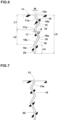
- Fig. 6 there is shown a cross-sectional view of the first sipe segment 11 taken along line A-A of Fig. 4 .
- Fig. 7 there is shown a cross-sectional view of the third sipe segment 13 taken along line B-B of Fig. 4 .
- at least one of the first sipe segment 11 and the third sipe segment 13 comprises an oscillated portion 15 extending in a tire radial direction, while oscillating in a lateral direction orthogonal to the above-said length direction in the cross section orthogonal to the above-said length direction.
- each of the first sipe segment 11 and the third sipe segment 13 comprises the oscillated portion 15.
- oscillated portion 15 maintains the rigidity of the tread portion 2 in the tire circumferential direction. Therefore, the traction performance and the braking performance on ice are further improved. In addition, such oscillated portion 15 also improves steering stability on a dry road surface.
- the first sipe segment 11 and the third sipe segment 13 extend at an angle of not more than 35 degrees with respect to the tire axial direction, for example.
- the angles of the first sipe segment 11 and the third sipe segment 13 with respect to the tire axial direction are desirably not more than 15 degrees, and more desirably not more than 5 degrees.
- the first sipe segment 11 and the third sipe segment 13 of the present embodiment as a more desirable embodiment extend parallel to the tire axial direction.
- the length of the first sipe segment 11 is the same as the length of the third sipe segment 13. Further, it is desirable that the length of the second sipe segment 12 and the length of the fourth sipe segment 14 are smaller than, for example, the length of the first sipe segment 11 or the length of the third sipe segment 13. In the present embodiment, the length of the second sipe segment 12 is the same as the length of the fourth sipe segment 14.
- the repeat unit 9 of the present embodiment is bent so that the four sipe segments 10 form angles ⁇ 1 of 30 to 70 degrees with each other. It is more desirable that the angle ⁇ 1 is 30 to 40 degrees.
- the angles of the acute-angled portions 10a formed by the respective sipe segments 10 are smaller than 30 degrees, the acute-angled portions 10a may be reduced in the rigidity, and tend to be reduced in the effect of suppressing the opening and displacement of the sipe 8. And there is a possibility that the frictional force in the tire axial direction provided by the repeat units 9 is reduced.
- the angles of the acute-angled portions 10a formed by the respective sipe segments 10 are all the same. However, the present invention is not limited to such embodiment.
- each of the oscillated portions 15 extends in the tire radial direction in a zigzag shape from the outer surface of the tread portion 2.
- the present invention is not limited to such example, and each of the oscillated portions 15 may extend in a sinusoidal shape in the tire radial direction, for example.
- the oscillated portion 15 of the first sipe segment 11 and the oscillated portion 15 of the third sipe segment 13 are formed to have the same wavelength of oscillation and amplitude of oscillation.
- the oscillated portion 15 of the first sipe segment 11 and the oscillated portion 15 of the third sipe segment 13 extend in the radial direction of the tire while oscillating in opposite phases to each other.
- Fig. 8 there is shown a graph which shows the rigidity of the block 6 (shown in Fig. 2 ) when the oscillated portion 15 of the first sipe segment 11 and the oscillated portion 15 of the third sipe segment 13 oscillate in opposite phases as described above.
- Fig. 9 there is shown a graph which shows the rigidity of the block 6 when the oscillated portion 15 of the first sipe segment 11 and the oscillated portion 15 of the third sipe segment 13 oscillate in the same phase.
- the horizontal axis represents the load in the tire circumferential direction acting on the block 6
- the vertical axis represents the rigidity in the tire circumferential direction of the block 6.
- the rigidity of the block 6 during traction and during braking is similar.
- the oscillated portion 15 of the first sipe segment 11 and the oscillated portion 15 of the third sipe segment 13 extend in the tire radial direction while oscillating in opposite phases, therefore, the rigidity of the block 6 is unlikely to have anisotropy in the tire circumferential direction. Therefore, the tire of the present invention can be uniformly improved in the traction performance and the braking performance.
- the tread pattern can be made non-directional.
- the oscillating-start portion 11a (shown in Fig. 6 ) of the first sipe segment 11 which is on the most tread surface side, is inclined to the second tire circumferential direction "b" side toward the inside in the radial direction of the tire.
- the oscillating-start portion 13a (shown in Fig. 7 ) of the third sipe segment 13 which is on the most tread surface side, is inclined to the first tire circumferential direction "a" side toward the inside in the radial direction of the tire.
- the oscillating-start portion 11a of the first sipe segment 11 and the oscillating-start portion 13a of the third sipe segment 13 are inclined in such directions that these are separated from each other toward the inside in the radial direction of the tire. Since a large rubber volume of the rubber piece surrounded by the sipe segments is secured, it is possible to suppress the rubber chipping at the time of demolding in the manufacturing process. Thereby, a large rubber volume of the rubber piece surrounded by the sipe segments is secured, therefore, it is possible to suppress rubber chipping during demolding in the manufacturing process.
- the oscillated portion 15 comprises two or more first convex portions 16 which are convex toward one side in the lateral direction.
- the oscillated portion 15 of the present embodiment is composed of the two first convex portions 16 and one second convex portion 17 which is convex toward the other side in the lateral direction between the two first convex portions 16. such oscillated portion 15 effectively suppresses shear deformation of the block 6 when the sipe walls come into contact with each other.
- the widthwise center line 15c of the oscillated portion 15 has a first vertex 16a at which a first convex portion 16 is bent, and a second vertex 17a at which a second convex portion 17 is bent. Further, it is desirable that a virtual straight line (not shown) drawn between both ends of the center line 15c of the oscillated portion 15 is parallel to the tire radial direction. Further, it is desirable that the second vertex 17a is positioned on the virtual straight line. As a result, the anisotropy of the rigidity of the block 6 in the tire circumferential direction is controlled. Further, the knife blade of the vulcanization mold forming the oscillated portion 15 is not easily deformed when it comes into contact with the raw rubber of the tire during vulcanization molding, and excellent moldability can be obtained.
- the center line 15c of the oscillated portion 15 has an outer end 15o on the outer side in the radial direction of the tire and an inner end 15i on the inner side in the radial direction of the tire.
- the oscillated portion 15 comprises a first bent element 18 from the outer end 15o to the second vertex 17a and a second bent element 19 from the second vertex 17a to the inner end 15i. It is desirable that the length L1 in the tire radial direction of the first bent element 18 is 0.8 to 1.2 times the length L2 in the tire radial direction of the second bent element 19. In the present embodiment, the length L1 is the same as the length L2.
- Such oscillated portion 15 can uniformly improve the traction performance and the braking performance on ice.
- the rigidity of the block 6 may not be sufficiently improved.
- the bending width "A" of the oscillated portion 15 is large, the bending of the block 6 when a vertical load is applied to the ground contacting surface of the block 6 increases, and there is a possibility that the steering stability on dry roads is deteriorated.
- the bending width "A” is large, the demolding of the knife blade of the vulcanization mold forming the bending width "A", at the time of vulcanization molding, tends to deteriorate.
- the bending width "A” of the oscillated portion 15 is, for example, 0.4 to 1.0 mm.
- the bending width "A” is the distance in the lateral direction from the first vertex 16a to the second vertex 17a.
- the length L4 in the tire radial direction of the linear bottom portion 22 is 0.10 to 0.30 times the length L3 in the tire radial direction of the sipe segment 10 to which the linear bottom portion 22 belongs.
- Fig. 10 there is shown a cross-sectional view of the second sipe segment 12 taken along line C-C of Fig. 4 .
- the second sipe segment 12 extends linearly in the radial direction of the tire.
- the fourth sipe segment 14 Thereby, when the first sipe segment 11 and the third sipe segment 13 are opened, the sipe walls of the second sipe segment 12 and of the fourth sipe segment 14 are easily brought into close contact with each other with a broad surface, therefore, the rigidity of the block 6 in the tire circumferential direction is improved.
- the second sipe segment 12 and the fourth sipe segment 14 extend in a zigzag shape in the radial direction of the tire, there is a possibility that the gap between the sipe walls facing each other becomes large, and the rigidity of the block 6 in the tire circumferential direction is decreased.
- Fig. 11 there is shown an enlarged plan view of a land portion 4 of an embodiment of the present invention.
- elements common to the above-described embodiment are denoted by the same reference numerals, and the descriptions thereof are omitted here.
- Fig. 12 (A) there is shown an enlarged view of repeat units 9.
- the first sipe segment 11 extends at an angle of +/- 5 degrees with respect to the tire axial direction, for example.
- the third sipe segment 13 is connected in series to the second sipe segment 12, and extends at an angle of +/- 5 degrees with respect to the tire axial direction.
- the first sipe segment 11 and the third sipe segment 13 extend at the angle of +/- 5 degrees in the tire axial direction, a large friction in the tire circumferential direction is provided when running on ice, and thereby, the traction on ice can be increased.
- each of the first sipe segment 11 and the third sipe segment 13 extends at an angle of +/- 3 degrees with respect to the tire axial direction.
- each of the first sipe segment 11 and the third sipe segment 13 of the present embodiment extends at an angle of 0 degree with respect to the tire axial direction.
- Fig. 12 (B) there is shown an enlarged view of the repeat units 9 when the sipe 8 is opened.
- the opened areas of the sipe 8 are colored so that the invention can be easily understood.
- the sipe walls facing each other in the second sipe segment 12 and in the fourth sipe segment 14 come into contact with each other, and thus it is possible to prevent the first sipe segment 11 and the third sipe segment 13 from opening excessively.
- Such action reduces the amount of slip between the road surface and the edges of the first sipe segment 11 and the third sipe segment 13 when the edges come out from the ground contact surface of the tread portion 2 as the tire rotates. Therefore, uneven wear in the vicinities of the edges is suppressed.
- the length L8 of the fourth sipe segment 14 is larger than the length L6 of the second sipe segment 12. Therefore, when a shear force acts on the repeat units 9, there is a tendency that the amount of shear deformation along the sipe walls of the fourth sipe segment 14 becomes larger than the amount of shear deformation along the sipe walls of the second sipe segment 12. As a result, the second sipe segment 12 and the fourth sipe segment 14 and a land piece 23 therebetween tend to cause twisting deformation when the ground pressure is applied. Therefore, the sipe walls of the second sipe segment 12 and/or the fourth sipe segment 14 can be strongly pressed against each other. Owing to this action, the opening of the first sipe segment 11 and the third sipe segment 13 can be further suppressed.
- the length L6 of the second sipe segment 12 is smaller than the length L5 of the first sipe segment 11 and the length L7 of the third sipe segment 13 in order to secure traction on ice.
- the length L8 of the fourth sipe segment 14 is smaller than the length L5 of the first sipe segment 11 and the length L7 of the third sipe segment 13.
- the length of each sipe segment is measured, for example, at the center line of the sipe.
- the fourth sipe segment 14 extends to the second tire circumferential direction side of a region extended toward the first tire axial direction from the first sipe segment 11 which is connected to the fourth sipe segment 14 through the second sipe segment 12 and the third sipe segment 13. Thereby, the end on the second tire circumferential direction side of the fourth sipe segment 14 is located on the second tire circumferential direction side of the first sipe segment 11.
- the sipe 8 having a plurality of such repeat units 9 can be arranged in an oblique direction, for example, to accord to a shape of the block, while securing a tire axial component by the first sipe segments 11 and the third sipe segments 13. Therefore, the sipe of the present invention can provide large traction on ice even when arranged in an oblique direction.
- the length L4 of the fourth sipe segment 14 is preferably not less than 1.10 times, more preferably not less than 1.20 times, and preferably not more than 1.50 times, more preferably not more than 1.40 times the length L2 of the second sipe segment 12.
- the repeat unit 9 having such fourth sipe segment 14 it is possible to increase the arrangement angle of the overall sipe with respect to the tire axial direction, while ensuring the traction on ice.
- the acute-angled portions 24 formed by the four sipe segments 10 are, for example, arranged at the same angle with each other.
- the acute-angled portions 24 are not limited to such example, and the angles may be different. It is desirable that the angles ⁇ 2 of the acute-angled portions 24 are, for example, not less than 45 degrees. Specifically, the angles ⁇ 2 of the acute-angled portions 24 are preferably 50 to 80 degrees.
- Such repeat unit 9 can secure an appropriate distance in the tire circumferential direction between the first sipe segment 11 and the third sipe segment 13, while exerting the above-mentioned effects, and can further increase the uneven wear resistance.
- the arrangement angle of the sipe 8 is, for example, 5 to 15 degrees. Such sipe 8 can provide a large frictional force in the tire circumferential direction.
- the arrangement angle of the sipe 8 is an angle with respect to the tire axial direction, of a straight line connecting between ends of the first sipe segments 11 which ends are adjacent to each other in the tire axial direction.
- Fig. 13 (A) there is shown a cross-sectional view taken along line D-D of Fig. 12 (A) .
- Fig. 13 (A) is a figure showing a cross section orthogonal to the length direction of each sipe segment 10. It is desirable that as shown in Fig. 13 (A) , each of the four sipe segments 10 extends in the tire radial direction in a zigzag shape in the cross section orthogonal to the length direction thereof.
- Fig. 13 (B) there is shown a cross-sectional view of the sipe segment 10 having the cross section shown in Fig. 13(A) during running. when loads in the tire radial direction and the tire circumferential direction are applied to the sipe segment 10 having the above cross-sectional shape, then as shown in Fig. 13 (B) , the sipe walls come into contact with each other and supports each other. Owing to this action, the deformation of the block is suppressed, and excellent steering stability can be obtained.
- a sipe having such a shape can be vulcanization molded by the use of a vulcanization mold having a sipe blade extending in a zigzag shape in the depth direction of the sipe.
- the maximum width of the zigzag amplitude is, for example, 2.0 to 3.0 times the opening width of the sipe.
- Pneumatic tires of size 195/65R15 provided with the above-described sipes were experimentally manufactured based on specifications shown in Table 1.
- Table 1 a tire in which the sipe did not have an oscillated portion and the entire sipe extended linearly in the radial direction of the tire, was experimentally manufactured. All the test tires had substantially the same configuration, except for the shape of the sipe.
- Each test tire was tested for traction performance on ice, braking performance on ice, cornering performance on ice, steering stability on dry roads, and uneven wear resistance. Specifications common to all the test tires and test methods are as follows.
- Pneumatic tires of size 185/65R15 provided with the above-described sipes were experimentally manufactured based on specifications shown in Table 1.
- a tire having a sipe "a” comprising a plurality of repeat units "b” shown in Fig. 14 (A) was experimentally manufactured.
- the repeat units "b” shown in Fig. 14 (A) are bent in a trapezoidal wavy shape so that sipe segments "c" form obtuse angles with each other.
- a tire having a sipe "d” shown in Fig. 14 (B) was experimentally manufactured.
- the first sipe segment “e” and the third sipe segment “g” were inclined at about 7 degrees with respect to the tire axial direction, and the second sipe segment “f” and the fourth sipe segment “h” had the same length as each other.
- All the test tires had substantially the same configuration, except for the shape of the sipe.
- Each test tire was tested for traction on ice, uneven wear resistance, and steering stability on dry roads. Specifications common to all the test tires and test methods are as follows.
- the wear energy of the sipe edge of each test tire was measured.
- the result is a reciprocal of the wear energy indicated by an index based on the comparative example 2 being 100, wherein the larger the value, the smaller the wear energy and the better the uneven wear resistance.
- test results are shown in Table 2.
- Table 2 comparative example 2 comparative example 3 working example 9 working example 10 working example 11 working example 12 working example 13 working example 14 working example 15 comparative example 4 figure showing sipe shape fig. 14(A) fig. 14(B) fig. 12(A) fig. 12(A) fig. 12(A) fig. 12(A) fig. 12(A) fig. 12(A) fig. 12(A) fig. 12(A) fig. 12(A) fig. 12(A) fig. 12(A) fig. 12(A) fig. 12(A) fig.
- the working example tires provided a large traction on ice while exhibiting excellent uneven wear resistance. Further, it was confirmed that, on a dry road surface, the working example tires exhibited steering stability equal to or higher than that of the comparative example 2.
Claims (15)
- Pneumatique (1) comprenant une portion formant bande de roulement (2), dans lequella portion formant bande de roulement (2) est dotée d'une fente (8), caractérisé en ce quela fente (8) comprend une portion dans laquelle une pluralité d'unités répétitives (9) sont connectées en série dans la direction longitudinale de la fente (8),chacune des unités répétitives (9) est fléchie de telle sorte que quatre segments de fente (10) forment des angles aigus les uns avec les autres,lesdits quatre segments de fente (10) incluentun premier segment de fente (11) s'étendant dans une direction axiale du pneumatique sous un angle de +/- 5 degrés par rapport à la direction axiale du pneumatique,un deuxième segment de fente (12) s'étendant depuis une extrémité dans une première direction axiale du pneumatique du premier segment de fente (11) vers une première direction circonférentielle du pneumatique (a),un troisième segment de fente (13) s'étendant dans la première direction axiale du pneumatique depuis le deuxième segment de fente (12) sous un angle de +/- 5 degrés par rapport à la direction axiale du pneumatique, etun quatrième segment de fente (14) connecté au troisième segment de fente (13) et s'étendant depuis le troisième segment de fente (13) vers une seconde direction circonférentielle du pneumatique (b) opposée à la première direction circonférentielle du pneumatique (a), la longueur du quatrième segment de fente (14) étant plus grande que la longueur du deuxième segment de fente (12), etl'un au moins du premier segment de fente (11) et du troisième segment de fente (13) comprend, dans la section transversale orthogonale à la direction longitudinale, une portion en oscillation (15) qui s'étend dans une direction radiale du pneumatique, tout en oscillant dans une direction latérale orthogonale à ladite direction longitudinale.
- Pneumatique (1) selon la revendication 1, dans lequel chacun du premier segment de fente (11) et du troisième segment de fente (13) comprend la portion en oscillation (15).
- Pneumatique (1) selon la revendication 2, dans lequel la portion en oscillation (15) du premier segment de fente (11) et la portion en oscillation (15) du troisième segment de fente (13) s'étendent dans la direction radiale du pneumatique (1) tout en oscillant dans des phases opposées.
- Pneumatique (1) selon l'une quelconque des revendications 1 à 3, dans lequel
l'unité répétitive (9) est fléchie de telle sorte que les quatre segments de fente (10) forment des angles de 30 à 70 degrés les uns avec les autres. - Pneumatique (1) selon l'une quelconque des revendications 1 à 4, dans lequel une portion de fond linéaire (22) s'étendant parallèlement à la direction radiale du pneumatique est connectée à un côté intérieur dans la direction radiale du pneumatique de la portion en oscillation (15).
- Pneumatique (1) selon la revendication 5, dans lequel une longueur (L4) dans la direction radiale du pneumatique de la portion de fond linéaire (22) est de 0,10 à 0,30 fois une longueur (L3) dans la direction radiale du pneumatique du segment de fente (10) auquel appartient la portion de fond linéaire (22).
- Pneumatique (1) selon l'une quelconque des revendications 1 à 6, dans lequel une largeur de flexion (A) de la portion en oscillation (15) est de 0,4 à 1,0 mm.
- Pneumatique (1) selon l'une quelconque des revendications 1 à 7, dans lequel la portion en oscillation (15) comprend deux ou plusieurs premières portions convexes (16) qui sont convexes vers un côté dans ladite direction latérale.
- Pneumatique (1) selon la revendication 8, dans lequel la portion en oscillation (15) est composé desdites deux premières portions convexes (16) et d'une seconde portion convexe (17) qui est convexe vers l'autre côté dans la direction latérale entre les deux premières portions convexes (16).
- Pneumatique (1) selon la revendication 9, dans lequel la ligne centrale (15c) dans la direction de la largeur de la portion en oscillation (15) comprend un premier sommet (16a) au niveau duquel la première portion convexe (16) est fléchie, et un second sommet (17a) au niveau duquel la seconde portion convexe (17) est fléchie,une ligne droite virtuelle tirée entre les deux extrémités de ladite ligne centrale (15c) est parallèle à la direction radiale du pneumatique, etle second sommet (17a) est positionné sur la ligne droite virtuelle.
- Pneumatique (1) selon la revendication 10, dans lequel ladite ligne centrale (15c) de la portion en oscillation (15) inclut une extrémité extérieure (15o) sur le côté extérieur dans la direction radiale du pneumatique (1) et une extrémité intérieure (15i) sur le côté intérieur dans la direction radiale du pneumatique (1),la portion en oscillation (15) comprend un premier élément fléchi (18) depuis l'extrémité extérieure (15o) jusqu'au second sommet (17a) et un second élément fléchi (19) depuis le second sommet (17a) jusqu'à l'extrémité intérieure (15i), etla longueur (L1) dans la direction radiale du pneumatique du premier élément fléchi (18) est la même que la longueur (L2) dans la direction radiale du pneumatique du second élément fléchi (19).
- Pneumatique (1) selon la revendication 1, dans lequel le quatrième segment de fente (14) s'étend vers le second côté de direction circonférentielle du pneumatique d'une région qui s'étend depuis le premier segment de fente (11) vers la première direction axiale du pneumatique.
- Pneumatique (1) selon la revendication 1 ou 12, dans lequel chacun du premier segment de fente (11) et du troisième segment de fente (13) s'étend sous un angle de 0 degré par rapport à la direction axiale du pneumatique.
- Pneumatique (1) selon l'une quelconque des revendications 1, 12 ou 13, dans lequel la longueur (L4) du quatrième segment de fente (14) est de 1,10 à 1,50 fois la longueur (L2) du second segment de fente (12).
- Pneumatique (1) selon l'une quelconque des revendications 1 ou 12 à 14, dans lequel chacun des quatre segments de fente (10) s'étend dans une forme en zigzag dans la section transversale orthogonale à leur direction longitudinale.
Applications Claiming Priority (3)
| Application Number | Priority Date | Filing Date | Title |
|---|---|---|---|
| JP2018174846A JP7139814B2 (ja) | 2018-09-19 | 2018-09-19 | タイヤ |
| JP2019098720A JP7207166B2 (ja) | 2019-05-27 | 2019-05-27 | タイヤ |
| PCT/JP2019/031046 WO2020059345A1 (fr) | 2018-09-19 | 2019-08-07 | Bandage |
Publications (3)
| Publication Number | Publication Date |
|---|---|
| EP3842262A1 EP3842262A1 (fr) | 2021-06-30 |
| EP3842262A4 EP3842262A4 (fr) | 2022-06-08 |
| EP3842262B1 true EP3842262B1 (fr) | 2024-01-10 |
Family
ID=69886950
Family Applications (1)
| Application Number | Title | Priority Date | Filing Date |
|---|---|---|---|
| EP19862350.6A Active EP3842262B1 (fr) | 2018-09-19 | 2019-08-07 | Bandage |
Country Status (4)
| Country | Link |
|---|---|
| US (1) | US11623479B2 (fr) |
| EP (1) | EP3842262B1 (fr) |
| CN (1) | CN112654512B (fr) |
| WO (1) | WO2020059345A1 (fr) |
Families Citing this family (1)
| Publication number | Priority date | Publication date | Assignee | Title |
|---|---|---|---|---|
| JP2021138313A (ja) | 2020-03-06 | 2021-09-16 | 住友ゴム工業株式会社 | タイヤ |
Family Cites Families (29)
| Publication number | Priority date | Publication date | Assignee | Title |
|---|---|---|---|---|
| DE19543940A1 (de) * | 1995-11-25 | 1997-05-28 | Continental Ag | Profilierter Fahrzeugreifen mit Feineinschnitten |
| JP3238101B2 (ja) | 1997-06-27 | 2001-12-10 | 住友ゴム工業株式会社 | 重荷重用空気入りタイヤ |
| FR2826911A1 (fr) * | 2001-07-09 | 2003-01-10 | Michelin Soc Tech | Bande de roulement pourvue d'incisions |
| JP4294532B2 (ja) * | 2004-04-09 | 2009-07-15 | 株式会社ブリヂストン | 空気入りタイヤ |
| FR2888163B1 (fr) * | 2005-07-05 | 2007-09-14 | Michelin Soc Tech | Bande de roulement comportant une sculpture avec des incisions. |
| JP4864577B2 (ja) * | 2006-07-10 | 2012-02-01 | 住友ゴム工業株式会社 | ラグ付き走行体 |
| JP4913508B2 (ja) * | 2006-08-30 | 2012-04-11 | 株式会社ブリヂストン | 空気入りタイヤ |
| JP4382080B2 (ja) * | 2006-12-07 | 2009-12-09 | 東洋ゴム工業株式会社 | 空気入りタイヤ |
| EP2234823B1 (fr) | 2007-12-19 | 2012-12-05 | Pirelli Tyre S.P.A. | Pneu pour roues de véhicule |
| JP2009214697A (ja) | 2008-03-10 | 2009-09-24 | Bridgestone Corp | 空気入りタイヤ |
| JP5563069B2 (ja) | 2009-05-29 | 2014-07-30 | ピレリ・タイヤ・ソチエタ・ペル・アツィオーニ | 冬用タイヤ |
| JP2011105131A (ja) * | 2009-11-17 | 2011-06-02 | Yokohama Rubber Co Ltd:The | 空気入りタイヤ |
| BR112012032222B1 (pt) | 2010-06-30 | 2020-11-17 | Pirelli Tyre S.P.A | pneu, e, banda de rodagem |
| DE102012103946A1 (de) | 2012-05-04 | 2013-11-07 | Continental Reifen Deutschland Gmbh | Laufstreifenprofil eines Fahrzeugreifens |
| DE102012103945A1 (de) | 2012-05-04 | 2013-11-07 | Continental Reifen Deutschland Gmbh | Laufstreifenprofil eines Fahrzeugreifens |
| DE102012103944A1 (de) | 2012-05-04 | 2013-11-07 | Continental Reifen Deutschland Gmbh | Laufstreifenprofil eines Fahrzeugreifens |
| US10507696B2 (en) | 2012-10-24 | 2019-12-17 | Bridgestone Corporation | Pneumatic tire |
| JP5873455B2 (ja) * | 2013-03-15 | 2016-03-01 | 住友ゴム工業株式会社 | 空気入りタイヤ |
| JP5603966B2 (ja) * | 2013-03-26 | 2014-10-08 | 株式会社ブリヂストン | タイヤ |
| GB201408941D0 (en) * | 2014-05-20 | 2014-07-02 | Apollo Tyres Global R & D B V | Tire profile and molding form |
| KR101619381B1 (ko) | 2014-08-19 | 2016-05-10 | 한국타이어 주식회사 | 스노 타이어의 트레드 커프 |
| JP6305313B2 (ja) | 2014-10-28 | 2018-04-04 | 東洋ゴム工業株式会社 | 空気入りタイヤ |
| JP2016088342A (ja) * | 2014-11-06 | 2016-05-23 | 東洋ゴム工業株式会社 | 空気入りタイヤ |
| JP6646407B2 (ja) * | 2015-11-05 | 2020-02-14 | Toyo Tire株式会社 | 空気入りタイヤ |
| JP6715067B2 (ja) * | 2016-04-20 | 2020-07-01 | 株式会社ブリヂストン | タイヤ |
| JP6711171B2 (ja) | 2016-06-27 | 2020-06-17 | 住友ゴム工業株式会社 | タイヤ |
| JP6759787B2 (ja) * | 2016-07-13 | 2020-09-23 | 住友ゴム工業株式会社 | タイヤ |
| US11712928B2 (en) * | 2016-07-27 | 2023-08-01 | Bridgestone Americas Tire Operations, Llc | Three-dimensional tire sipe |
| JP6822095B2 (ja) * | 2016-11-24 | 2021-01-27 | 住友ゴム工業株式会社 | タイヤ |
-
2019
- 2019-08-07 WO PCT/JP2019/031046 patent/WO2020059345A1/fr unknown
- 2019-08-07 CN CN201980057532.XA patent/CN112654512B/zh active Active
- 2019-08-07 US US17/275,228 patent/US11623479B2/en active Active
- 2019-08-07 EP EP19862350.6A patent/EP3842262B1/fr active Active
Also Published As
| Publication number | Publication date |
|---|---|
| EP3842262A1 (fr) | 2021-06-30 |
| CN112654512B (zh) | 2023-09-05 |
| US20220024257A1 (en) | 2022-01-27 |
| WO2020059345A1 (fr) | 2020-03-26 |
| CN112654512A (zh) | 2021-04-13 |
| EP3842262A4 (fr) | 2022-06-08 |
| US11623479B2 (en) | 2023-04-11 |
Similar Documents
| Publication | Publication Date | Title |
|---|---|---|
| EP3326840B1 (fr) | Pneumatique | |
| EP3178668B1 (fr) | Pneumatique | |
| CN106042780B (zh) | 充气轮胎 | |
| EP2578418B1 (fr) | Pneu | |
| CN107199833B (zh) | 充气轮胎 | |
| EP3421263B1 (fr) | Pneumatique | |
| EP3012119B1 (fr) | Pneumatique | |
| EP2450200B1 (fr) | Bandage pneumatique | |
| EP3263365B1 (fr) | Pneumatique | |
| EP3335910B1 (fr) | Pneumatique | |
| EP3401123B1 (fr) | Pneumatique | |
| CN110525131B (zh) | 轮胎 | |
| EP3263366B1 (fr) | Pneumatique | |
| EP3549791B1 (fr) | Pneumatique | |
| US20230322028A1 (en) | Tire | |
| CN108688410B (zh) | 轮胎 | |
| EP3842262B1 (fr) | Bandage | |
| EP3925799B1 (fr) | Pneumatique | |
| JP7172106B2 (ja) | タイヤ | |
| US11691459B2 (en) | Tire | |
| JP7207166B2 (ja) | タイヤ | |
| EP4316871A1 (fr) | Pneumatique | |
| EP3925796B1 (fr) | Pneu | |
| EP4000961A1 (fr) | Pneumatique | |
| CN111038180B (zh) | 轮胎 |
Legal Events
| Date | Code | Title | Description |
|---|---|---|---|
| STAA | Information on the status of an ep patent application or granted ep patent |
Free format text: STATUS: THE INTERNATIONAL PUBLICATION HAS BEEN MADE |
|
| PUAI | Public reference made under article 153(3) epc to a published international application that has entered the european phase |
Free format text: ORIGINAL CODE: 0009012 |
|
| STAA | Information on the status of an ep patent application or granted ep patent |
Free format text: STATUS: REQUEST FOR EXAMINATION WAS MADE |
|
| 17P | Request for examination filed |
Effective date: 20210324 |
|
| AK | Designated contracting states |
Kind code of ref document: A1 Designated state(s): AL AT BE BG CH CY CZ DE DK EE ES FI FR GB GR HR HU IE IS IT LI LT LU LV MC MK MT NL NO PL PT RO RS SE SI SK SM TR |
|
| DAV | Request for validation of the european patent (deleted) | ||
| DAX | Request for extension of the european patent (deleted) | ||
| A4 | Supplementary search report drawn up and despatched |
Effective date: 20220511 |
|
| RIC1 | Information provided on ipc code assigned before grant |
Ipc: B60C 11/12 20060101AFI20220504BHEP |
|
| P01 | Opt-out of the competence of the unified patent court (upc) registered |
Effective date: 20230510 |
|
| GRAP | Despatch of communication of intention to grant a patent |
Free format text: ORIGINAL CODE: EPIDOSNIGR1 |
|
| STAA | Information on the status of an ep patent application or granted ep patent |
Free format text: STATUS: GRANT OF PATENT IS INTENDED |
|
| INTG | Intention to grant announced |
Effective date: 20231011 |
|
| GRAS | Grant fee paid |
Free format text: ORIGINAL CODE: EPIDOSNIGR3 |
|
| GRAA | (expected) grant |
Free format text: ORIGINAL CODE: 0009210 |
|
| STAA | Information on the status of an ep patent application or granted ep patent |
Free format text: STATUS: THE PATENT HAS BEEN GRANTED |
|
| AK | Designated contracting states |
Kind code of ref document: B1 Designated state(s): AL AT BE BG CH CY CZ DE DK EE ES FI FR GB GR HR HU IE IS IT LI LT LU LV MC MK MT NL NO PL PT RO RS SE SI SK SM TR |
|
| REG | Reference to a national code |
Ref country code: GB Ref legal event code: FG4D |
|
| REG | Reference to a national code |
Ref country code: CH Ref legal event code: EP |
|
| REG | Reference to a national code |
Ref country code: DE Ref legal event code: R096 Ref document number: 602019045027 Country of ref document: DE |
|
| REG | Reference to a national code |
Ref country code: IE Ref legal event code: FG4D |