EP3842239B1 - Tintenstrahldruckvorrichtung und anpassungsmusterdruckverfahren - Google Patents
Tintenstrahldruckvorrichtung und anpassungsmusterdruckverfahren Download PDFInfo
- Publication number
- EP3842239B1 EP3842239B1 EP20214705.4A EP20214705A EP3842239B1 EP 3842239 B1 EP3842239 B1 EP 3842239B1 EP 20214705 A EP20214705 A EP 20214705A EP 3842239 B1 EP3842239 B1 EP 3842239B1
- Authority
- EP
- European Patent Office
- Prior art keywords
- patches
- scanning direction
- printing device
- printing
- Prior art date
- Legal status (The legal status is an assumption and is not a legal conclusion. Google has not performed a legal analysis and makes no representation as to the accuracy of the status listed.)
- Active
Links
Images


Classifications
-
- B—PERFORMING OPERATIONS; TRANSPORTING
- B41—PRINTING; LINING MACHINES; TYPEWRITERS; STAMPS
- B41J—TYPEWRITERS; SELECTIVE PRINTING MECHANISMS, i.e. MECHANISMS PRINTING OTHERWISE THAN FROM A FORME; CORRECTION OF TYPOGRAPHICAL ERRORS
- B41J2/00—Typewriters or selective printing mechanisms characterised by the printing or marking process for which they are designed
- B41J2/005—Typewriters or selective printing mechanisms characterised by the printing or marking process for which they are designed characterised by bringing liquid or particles selectively into contact with a printing material
- B41J2/01—Ink jet
- B41J2/21—Ink jet for multi-colour printing
- B41J2/2132—Print quality control characterised by dot disposition, e.g. for reducing white stripes or banding
- B41J2/2135—Alignment of dots
-
- B—PERFORMING OPERATIONS; TRANSPORTING
- B41—PRINTING; LINING MACHINES; TYPEWRITERS; STAMPS
- B41J—TYPEWRITERS; SELECTIVE PRINTING MECHANISMS, i.e. MECHANISMS PRINTING OTHERWISE THAN FROM A FORME; CORRECTION OF TYPOGRAPHICAL ERRORS
- B41J19/00—Character- or line-spacing mechanisms
- B41J19/14—Character- or line-spacing mechanisms with means for effecting line or character spacing in either direction
- B41J19/142—Character- or line-spacing mechanisms with means for effecting line or character spacing in either direction with a reciprocating print head printing in both directions across the paper width
- B41J19/145—Dot misalignment correction
-
- B—PERFORMING OPERATIONS; TRANSPORTING
- B41—PRINTING; LINING MACHINES; TYPEWRITERS; STAMPS
- B41J—TYPEWRITERS; SELECTIVE PRINTING MECHANISMS, i.e. MECHANISMS PRINTING OTHERWISE THAN FROM A FORME; CORRECTION OF TYPOGRAPHICAL ERRORS
- B41J11/00—Devices or arrangements of selective printing mechanisms, e.g. ink-jet printers or thermal printers, for supporting or handling copy material in sheet or web form
- B41J11/0045—Guides for printing material
- B41J11/005—Guides in the printing zone, e.g. guides for preventing contact of conveyed sheets with printhead
-
- B—PERFORMING OPERATIONS; TRANSPORTING
- B41—PRINTING; LINING MACHINES; TYPEWRITERS; STAMPS
- B41J—TYPEWRITERS; SELECTIVE PRINTING MECHANISMS, i.e. MECHANISMS PRINTING OTHERWISE THAN FROM A FORME; CORRECTION OF TYPOGRAPHICAL ERRORS
- B41J2/00—Typewriters or selective printing mechanisms characterised by the printing or marking process for which they are designed
- B41J2/005—Typewriters or selective printing mechanisms characterised by the printing or marking process for which they are designed characterised by bringing liquid or particles selectively into contact with a printing material
- B41J2/01—Ink jet
- B41J2/21—Ink jet for multi-colour printing
- B41J2/2132—Print quality control characterised by dot disposition, e.g. for reducing white stripes or banding
- B41J2/2142—Detection of malfunctioning nozzles
-
- B—PERFORMING OPERATIONS; TRANSPORTING
- B41—PRINTING; LINING MACHINES; TYPEWRITERS; STAMPS
- B41J—TYPEWRITERS; SELECTIVE PRINTING MECHANISMS, i.e. MECHANISMS PRINTING OTHERWISE THAN FROM A FORME; CORRECTION OF TYPOGRAPHICAL ERRORS
- B41J2/00—Typewriters or selective printing mechanisms characterised by the printing or marking process for which they are designed
- B41J2/005—Typewriters or selective printing mechanisms characterised by the printing or marking process for which they are designed characterised by bringing liquid or particles selectively into contact with a printing material
- B41J2/01—Ink jet
- B41J2/21—Ink jet for multi-colour printing
- B41J2/2132—Print quality control characterised by dot disposition, e.g. for reducing white stripes or banding
- B41J2/2146—Print quality control characterised by dot disposition, e.g. for reducing white stripes or banding for line print heads
-
- G—PHYSICS
- G06—COMPUTING OR CALCULATING; COUNTING
- G06K—GRAPHICAL DATA READING; PRESENTATION OF DATA; RECORD CARRIERS; HANDLING RECORD CARRIERS
- G06K15/00—Arrangements for producing a permanent visual presentation of the output data, e.g. computer output printers
- G06K15/02—Arrangements for producing a permanent visual presentation of the output data, e.g. computer output printers using printers
- G06K15/027—Test patterns and calibration
-
- H—ELECTRICITY
- H04—ELECTRIC COMMUNICATION TECHNIQUE
- H04N—PICTORIAL COMMUNICATION, e.g. TELEVISION
- H04N1/00—Scanning, transmission or reproduction of documents or the like, e.g. facsimile transmission; Details thereof
- H04N1/40—Picture signal circuits
- H04N1/407—Control or modification of tonal gradation or of extreme levels, e.g. background level
- H04N1/4076—Control or modification of tonal gradation or of extreme levels, e.g. background level dependent on references outside the picture
- H04N1/4078—Control or modification of tonal gradation or of extreme levels, e.g. background level dependent on references outside the picture using gradational references, e.g. grey-scale test pattern analysis
-
- H—ELECTRICITY
- H04—ELECTRIC COMMUNICATION TECHNIQUE
- H04N—PICTORIAL COMMUNICATION, e.g. TELEVISION
- H04N1/00—Scanning, transmission or reproduction of documents or the like, e.g. facsimile transmission; Details thereof
- H04N1/46—Colour picture communication systems
- H04N1/56—Processing of colour picture signals
- H04N1/60—Colour correction or control
- H04N1/603—Colour correction or control controlled by characteristics of the picture signal generator or the picture reproducer
- H04N1/6033—Colour correction or control controlled by characteristics of the picture signal generator or the picture reproducer using test pattern analysis
-
- B—PERFORMING OPERATIONS; TRANSPORTING
- B41—PRINTING; LINING MACHINES; TYPEWRITERS; STAMPS
- B41J—TYPEWRITERS; SELECTIVE PRINTING MECHANISMS, i.e. MECHANISMS PRINTING OTHERWISE THAN FROM A FORME; CORRECTION OF TYPOGRAPHICAL ERRORS
- B41J29/00—Details of, or accessories for, typewriters or selective printing mechanisms not otherwise provided for
- B41J29/38—Drives, motors, controls or automatic cut-off devices for the entire printing mechanism
- B41J29/393—Devices for controlling or analysing the entire machine ; Controlling or analysing mechanical parameters involving printing of test patterns
- B41J2029/3935—Devices for controlling or analysing the entire machine ; Controlling or analysing mechanical parameters involving printing of test patterns by means of printed test patterns
Definitions
- the present invention relates to an inkjet printing apparatus and an adjustment pattern printing method in the apparatus.
- Some inkjet printing apparatus is capable of executing a print position adjustment mode for adjusting the print positions of dots on a print medium. For example, in the case of adjusting the print positions in outward and return scans, multiple patches in which the relative print position in the outward scan and return scan by a print head is gradually shifted are printed on a print medium in the print position adjustment mode. Then, the patch that achieved the smallest print position misalignment is selected and the print position used in the selected patch is set as an adjustment value.
- Japanese Patent Laid-Open No. 2010-143123 discloses a print position adjustment method in which multiple patches having mutually different dot print positions are printed in association with respective platen ribs that support a print medium, thereby keeping small an influence due to a variation of the distance between the print head and the print medium.
- JP 4 894881 B2 discloses printing of a plurality of patterns for adjusting a liquid discharge timing.
- US 9 186 886 B2 discloses forming a plurality of thickness measurement patterns and judging patterns on pattern forming areas defined on a print medium.
- an object of the present invention is to execute a print position adjustment mode with high accuracy while saving consumption of print media.
- the present invention in its first aspect provides a printing apparatus as specified in claims 1 to 21.
- the present invention in its second aspect provides an adjustment pattern printing method as specified in claims 22 and 23.
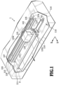
- Fig. 1 is a schematic perspective view of an inkjet printing apparatus 1 (hereinafter, also referred to as the printing apparatus 1) to which the present invention is applicable.
- a carriage 102 is capable of reciprocating in an X direction along a guide shaft 103 that extends in the X direction.
- the carriage 102 is driven by a main scanning motor 104 via a driving mechanism including a motor pulley 105, a driven pulley 106, a timing belt 107, and so on, and an encoder 1304 detects the position of the carriage 102 moved in the X direction.
- a head cartridge 101 is mounted on the carriage 102 and a reflection-type optical sensor 130 is attached to a side portion of the carriage 102.
- a platen 1301 is arranged at a position opposed to a downwardly-projecting ejection port surface (not illustrated in Fig. 1 ) of the head cartridge 101 and supports the print medium P being convened from the back side.
- the structure of the platen 1301 will be described later.
- the conveyance roller pairs 109 and 111 are part of a conveyance unit or a conveyor.
- the conveyor includes the conveyance roller pairs 109 and 111 and a conveying functionality provided by the CPU 901 (shown in Fig. 6 ) that performs the conveying operation.
- a recovery treatment unit 114 for maintaining good ink ejection conditions in the head cartridge 101 is arranged at an end portion of a movable region of the head cartridge 101.
- the recovery treatment unit 114 is equipped with a cap 115 that caps the ejection port surface of the head cartridge 101, a suction pump 116, a wiper 118, and so on.
- Figs. 2A and 2B are perspective views for explaining the structure of the head cartridge 101.
- the head cartridge 101 includes ink tanks 201 that store inks and a print head 202 that ejects the inks supplied from the ink tanks 201.
- Fig. 2A illustrates a state where the ink tanks 201 are mounted on the print head 202
- Fig. 2B illustrates a state where the ink tanks 201 are not mounted on the print head 202.
- the ink tanks 201 of colors of black, light cyan, light magenta, cyan, magenta, and yellow are detachably mounted.
- the print head 202 is an inkjet print head that ejects the inks by using thermal energy, and includes electric thermal conversion member. More specifically, the print head 202 boils the inks by using the thermal energy generated by the electric heat converters, and ejects the inks from its ejection ports to the print medium by using the bubble generating energy.
- the print head 202 may use piezo elements or the like as elements for generating the ink ejection energy.
- the print head 202 is part of a printing unit or a printer which includes the print head 202 and a function performed by a processor or a programmable device such as the central processing unit (CPU) 901 shown in Fig. 6 .
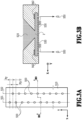
- Figs. 3A and 3B are diagrams for explaining a structure for one color in the print head 202.
- Fig. 3A illustrates an array structure of ejection ports 500 in an ejection port surface 510 and Fig. 3B illustrates a cross-sectional view taken along IIIB-IIIB.
- multiple ejection ports 500 from which the ink is ejectable are arranged in two arrays 501 and 502 in the ejection port surface 510.
- the ejection port arrays 501 and 502 extend in a Y direction in which the print medium is conveyed.
- 384 ejection ports 500 are formed at pitches Py, specifically, at intervals each corresponding to 600 dpi. Then, the ejection ports 500 in the ejection port array 501 are shifted in the Y direction from the ejection ports 500 in the ejection port array 502 by a half pitch (Py/2) corresponding to 1200 dpi.
- the ink of the same color is ejected, so that dots can be printed at a density of 1200 dpi in the Y direction.
- a common channel 520 through which the ink is supplied to the ejection port array 501 and the ejection port array 502 is formed between the ejection port array 501 and the ejection port array 502.
- the ink in the common channel 520 is guided to each of the ejection ports 500 in the ejection port arrays 501 and 502 through an individual channel 530.
- an ejection heater 942 formed of an electric heat converter is arranged at a position opposed to the ejection port 500.
- the ejection heater 942 driven according to a drive signal When the ejection heater 942 driven according to a drive signal generates thermal energy, the ink in the individual channel 530 causes film boiling, and the bubble generating energy at that time causes an ink droplet 550 to be ejected from the ejection port 500.
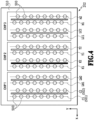
- Fig. 4 is a diagram illustrating the array structure of the ejection ports 500 for six colors in the ejection port surface 510.
- the print head 202 in the present embodiment supports inks of six colors of cyan (C), magenta (M), yellow (Y), black (K), light cyan (LC), and light magenta (LM).
- C1 and C2 denote ejection port arrays for ejecting the ink of cyan (C)
- LM1 and LM2 denote ejection port arrays for ejecting the ink of light magenta (LM).
- K1 and K2 denote ejection port arrays for ejecting the ink of black (K) and Y1 and Y2 denote ejection port arrays for ejecting the ink of yellow (Y).
- LC1 and LC2 denote ejection port arrays for ejecting the ink of light cyan (LC) and M1 and M2 denote ejection port arrays for ejecting the ink of magenta (M).
- the ejection port arrays C1, C2, LM1, and LM2 are provided in a common board (chip 1), the ejection port arrays K1, K2, Y1, and Y2 are provided in a common board (chip 2), and the ejection port arrays LC1, LC2, M1, and M2 are provided in a common board (chip 3).
- the inks of cyan (C), magenta (M), yellow (Y), and black (K) are thick inks each having a relatively high dye concentration, while the inks of light cyan (LC) and light magenta (LM) are light inks each having a dye concentration of about one-sixth of those of the thick inks.
- Fig. 5 is a schematic diagram for explaining the reflection-type optical sensor 130 (see Fig. 1 ) attached to the carriage 102.
- the reflection-type optical sensor 130 includes a light emitter 801 and a light receiver 802. Incident light 803 emitted from the light emitter 801 is reflected by a print medium P and then is detected by the light receiver 802.
- a detection signal (analog signal) of the light receiver 802 is transmitted to a control circuit on an electric board of the printing apparatus 1 through a flexible cable not illustrated, and is converted to a digital signal by an A/D converter.
- a controller 900 as a main controller includes, for example, a CPU 901 in the form of a microcomputer, a ROM 902 that stores programs, necessary tables, and other fixed data, and a RAM 903 on which an area for developing image data, a work area, and so on are provided.
- the CPU 901 performs operations by executing a function or a program stored in the ROM 902 or an equivalent memory device.
- the operations may include functionalities of a printing unit or printer, a scanning unit or scanner, and a conveyance unit or conveyor.
- a host device 910 is a supply source of image data, and may be in the form of not only a computer that performs creation, processing, and the like of image data for printing, but also a reader or the like for image reading.
- the host device 910 transmits and receives image data, other commands, status signals, and so on to and from the controller 900 via an interface (I/F) 911.
- I/F interface
- An operation unit 920 is a switch group that accepts input of instructions by an operator, and includes a power supply switch 921, a printing start switch 922 for making an instruction to start printing, and a recovery switch 923 for making an instruction to activate a recovery operation for the print head 202. Moreover, the operation unit 920 includes a print position adjustment start switch 924 for starting a print position adjustment mode to be described later. In the present embodiment, execution of the print operation, the recovery operation for the print head 202, and the print position adjustment mode can be instructed through the switches in the operation unit 920. Instead, these operations may be executed based on instructions from the host device 910.
- a sensor group 930 includes the reflection-type optical sensor 130 described with reference to Fig. 5 , a photocoupler 931 for detecting a home position, a temperature sensor 932 provided at an appropriate position for detecting an environment temperature, and so on.
- a head driver 940 is a driver that drives the ejection heaters 942 in the print head 202 according to print data or the like.
- the head driver 940 includes a shift register that aligns print data with the positions of the ejection heaters 942, a latch circuit that performs a latching action at an appropriate timing, and a logic circuit element that operates the ejection heaters 942 in synchronization with drive timing signals.
- the print head 202 includes sub-heaters 941 for temperature adjustment of the ink before ejection in addition to the ejection heaters 942 described with reference to Fig. 3B .
- the sub-heaters 941 may be provided on the same board as the ejection heaters 942 or provided at a portion other than the board in the print head 202.
- a main scanning motor driver 950 is a driver that drives the main scanning motor 104.
- a sub scanning motor driver 960 is a driver that drives a sub scanning motor 961 that rotates the conveyance roller pairs 109 and 111.
- a recovery motor driver 970 is a driver that operates the suction pump 116, the wiper 118, and so on in the recovery treatment unit 114.
- Fig. 7 is a flowchart for explaining steps in processing of the print position adjustment mode in the present embodiment.
- This processing is processing that the CPU 901 executes according to a program stored in the ROM 902 by using the RAM 903 as a work area. This processing is started in the case where a user presses down the print position adjustment start switch 924 or a command for print position adjustment is inputted from the host device 910.
- the CPU 901 Upon start of this processing, the CPU 901 first executes adjustment pattern print processing for printing a predetermined adjustment pattern on a print medium P at S 1.
- the adjustment pattern includes multiple patches for each of items for which the print positions are to be adjusted, which will be described in detail later.
- the CPU 901 measures an optical density of each of the patches included in the adjustment pattern by using the reflection-type optical sensor 130.
- the CPU 901 determines a print position adjustment value for each of the items based on the optical densities of the corresponding patches obtained at S2.
- the CPU 901 stores the adjustment values determined at S3 in association with the respective items in the ROM 902. This processing is completed at the end of this step.
- the adjustment values stored at S4 are used in following print operations, and enable the printing apparatus 1 to output an image having no print position misalignment.
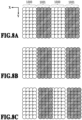
- Figs. 8A to 8C are diagrams illustrating an example of the patches printed at S 1 in Fig. 7 .
- a case where an adjustment value is obtained for the print positions in the outward and return scans as an item is described as an example.
- one patch includes a first dot group 1000 printed in the outward scan and a second dot group 1001 printed in the return scan.
- each of the first dot group 1000 and the second dot group 1001 is a pattern in which four pixels where dots are printed consecutively and four pixels where any dots are not printed consecutively are alternately repeated in a main scanning direction. Then, at S 1 in Fig.
- multiple patches where a shift amount in the X direction between these two dot groups is gradually changed are printed on the print medium. More specifically, a timing for applying a voltage to the ejection heaters 942 to print the second dot group in the return scan is shifted on a patch-by-patch basis relative to a timing for applying a voltage to the ejection heaters 942 to print the first dot group in the outward scan.
- Figs. 8A to 8C illustrate three patches among which the aforementioned ejection timings are different.
- Fig. 8A illustrates a state where the print positions of the first dot group 1000 and the second dot group 1001 are aligned with each other, in other words, the case where the ejection timing in the outward scan and the ejection timing in the return scan are in favorable conditions.
- Fig. 8B illustrates a state where the second dot group 1001 is misaligned with the first dot group 1000 in the right direction
- Fig. 8C illustrates a state where the aforementioned misalignment is further greater than in Fig. 8B .
- the optical density decreases in the order of the patch in Fig. 8A , the patch in Fig. 8B , and the patch in Fig. 8C , that is, in ascending order of the misalignment.
- Fig. 9 is a diagram illustrating a relation between the print position misalignment and the optical density.
- the horizontal axis indicates the misalignment of the second dot group 1001 relative to the first dot group 1000 in a patch, and the vertical axis indicates the optical density of the patch.
- the optical density is a detected density D obtained by using the reflection-type optical sensor 130 described with reference to Fig. 5 .
- the detected density D is a logarithmic function of the reciprocal of the reflectance R, and can be calculated in accordance with the following equation using the reflectance R.
- D Log 10 1 / R
- the area factor on the print medium is approximately 100% as in Fig. 8A and the detected density is the highest value. Then, as the misalignment between the print positions in any of the right and left directions increases, the area factor decreases and accordingly the detected density becomes lower.
- the CPU 901 compares the detected densities of the patches with each other, and determines the print position in the patch with the highest detected density as the adjustment value.
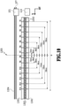
- Fig. 10 is a top view illustrating a layout of platen ribs 1303 in a platen 1301 that extend in the X direction. Although a scanning region of the head cartridge 101 is actually right above the platen 1301, the scanning region is shifted in the Y direction in Fig. 10 for the purpose of explaining the positional relationship between them in the X direction.
- Fig. 10 illustrates a state where the head cartridge 101 is located at the recovery treatment unit 114 outside a printable region W where the head cartridge 101 can actually print images.
- the platen 1301 is a plate that extends in the X direction.
- the platen 1301 is provided in two rows at a predetermined interval in the Y direction, and an ink absorber 1302 for absorbing the ink flowing out of the edges of a print medium during a print operation is provided between the two rows of the platen 1301.
- On the platen 1301, multiple platen ribs 1303 projecting upward are formed at predetermined pitches in the X direction. More specifically, these platen ribs 1303 are arranged on a conveyance route of the print medium and support the print medium being conveyed from the back side. The position of each of the platen ribs 1303 in the X direction is managed in association with a coordinate in the encoder 1304.
- the platen ribs 1303 are arranged symmetrically with respect to a center line 1305 of the printable region W.
- R1 denotes the platen rib 1303 located closest to the recovery treatment unit 114 and R2, R3, ..., R14 denote the platen ribs 1303 in ascending order of the distance from the recovery treatment unit 114.
- Fig. 10 indicates the distance between the center line 1305 and each platen rib 1303.
- the print medium P being conveyed on the platen ribs 1303 in the Y direction is conveyed with the center of the print medium P aligned with the center line 1305 irrespective of the size of the print medium.
- the layout of the platen ribs 1303 is determined depending on the size of a print medium supposed to be conveyed and the rib pitches between the two neighboring platen ribs 1303 are not constant. For example, in the case where a print medium is in A4 size, the print medium is conveyed in the Y direction at an internal position between the platen ribs 1303 of R3 and R12 while being supported by the eight platen ribs 1303 of R4 to R11.
- Fig. 11 is a diagram illustrating a state where the three platen ribs 1303 of R7, R8, and R9 support a print medium P being conveyed.
- the platen ribs 1303 have a height of approximately 2 mm, and their tip ends come into contact with the back side of the print medium P and thereby support the print medium P.
- the pitch between R7 and R8 and the pitch between R8 and R9 are both 24 mm.
- a portion supported by each of the platen ribs 1303 is in an upwardly-projecting form and a portion between the two platen ribs 1303 is in a recessed form.
- an intra-sheet maximum variation is defined as a difference between the projecting portion and the lowest point of the recessed portion.
- This intra-sheet maximum variation in a print medium having a low stiffness such as a plain sheet, for example, is approximately 200 ⁇ m.
- a distance between the ejection port surface of the print head 202 and the print medium P (a head-to-paper distance) has a variation of 200 ⁇ m in the X direction.
- Figs. 12A and 12B are diagrams for explaining print position misalignment between the outward scan and the return scan due to a difference in the head-to-paper distance.
- the print head 202 ejects the ink to the print medium P at an ejection velocity Vz while moving at a velocity Vx in the +X direction.
- an ink droplet ejected also has the velocity Vx in the +X direction and is landed to form the dot at a position shifted in the +X direction from the position where the print head 202 ejects the ink droplet.
- the print head 202 ejects the ink to the print medium P at the ejection velocity Vz while moving at the velocity Vx in the -X direction.
- an ink droplet ejected also has the velocity -Vx in the -X direction and is landed to form the dot at a position shifted in the - X direction from the position where the print head 202 ejects the ink droplet.
- Fig. 12A illustrates a state where the position of the ink landed in the outward scan and the position of the ink landed in the return scan coincide with each other with a head-to-paper distance d1.
- Fig. 12B illustrates a case where ejection actions are performed with a head-to-paper distance d2 (> d1) at the same timings as in Fig. 12A .
- a time from the ejection to the landing of the ink droplet increases, and accordingly the traveling distance in the X direction also increases. For this reason, even though the ejection actions are performed at the same timings as in Fig. 12A , the dot printed in the outward scan and the dot printed in the return scan are formed at different positions and thus a misalignment with a distance s occurs between the two dots.
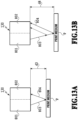
- Figs. 13A and 13B are diagrams illustrating an influence of a difference in the head-to-paper distance on the detection accuracy of the reflection-type optical sensor 130.
- Fig. 13A illustrates a case where an optical density of the print medium P is measured under the condition that a distance between the reflection-type optical sensor 130 and the print medium P is d3.
- the incident light 803 emitted from the light emitter 801 is reflected by the print medium P and the reflected light 804 is incident on the substantially center of the light receiver 802.
- Fig. 13B illustrates a case where an optical density of the print medium P is measured under the condition that the distance between the reflection-type optical sensor 130 and the print medium P is d4 (> d3).
- the reflected light 804 is shifted in the X direction and is incident on an edge portion of the light receiver 802. Thus, even if the measurement is performed on the same image, the optical density detected by the reflection-type optical sensor 130 varies between Figs. 13A and 13B .
- a variation of the head-to-paper distance illustrated in Fig. 11 is a factor that reduces the accuracy of the print positions and the measurement accuracy of the optical density.
- the head-to-paper distance at each of the positions on the print medium where the multiple patches are arranged is required to be stable in the process of conveying the print medium. From this point of view, it can be said that the printing of multiple patches in association with the respective platen ribs as in Japanese Patent Laid-Open No. 2010-143123 is effective for maintaining the accuracy of the print position adjustment.
- a print medium in, for example, A4 size allows only eight patches above R4 to R11 to be arranged in the X direction (see Fig. 10 ).
- the inkjet printing apparatus 1 requires print position adjustments for various items including not only the above-described print positions in the outward and return scans, but also the print positions of the inks of different colors (see Fig. 6 ), the print positions of the ejection port arrays (see Fig. 3A ), and so on. Under such circumstances, printing of all the patches for all the items on a print medium or print media requires a print medium in a large size having no versatility or consumes multiple print media for the print position adjustment mode, which is unfavorable in terms of the usability.
- the present inventors considered that it is effective to confirm in advance ranges on both sides of each platen rib 1303 where the influence of the print position misalignment due to a variation of the head-to-paper distance is tolerable and to arrange a plurality of the above patches within the confirmed ranges. Then, in the case of Fig. 11 , the studies by the present inventors confirmed that a variation of the head-to-paper distance within a range of 25% of the distance from R8 to R7 or R9, specifically, within a 6 mm area on either of the right and left sides is kept as low as approximately 100 ⁇ m, which is half of the intra-sheet maximum variation of 200 ⁇ m.
- the influence on the accuracy of the print position adjustment is only at a level of several ⁇ m and the influence on image quality in the inkjet printing apparatus of the present embodiment that prints images at a print resolution of 1200 dip can be kept within a tolerable range.
- one patch is printed within a 6 mm area on one side of the platen rib 1303 and another patch having a shift amount different from that in the former patch is printed within a 6 mm area on the other side of the platen rib 1303.
- the number of patches printable in the width direction of the print medium can be increased as compared with a case in the related art.
- the present inventors first confirmed the size of a patch necessary to normally measure the optical density.
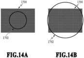
- Figs. 14A and 14B are diagrams each depicting a relation between one patch 1700 and a spot diameter 1702 of the incident light 803 of the reflection-type optical sensor 130 (see Fig. 5 ) on a print medium.
- the spot diameter 1702 be within the area of the patch 1700 as in Fig. 14A for the following reason. If the spot diameter 1702 protrudes from the area of the patch 1700 as illustrated in Fig. 14B , the detected density tends to be affected by a variation of the light incident position, and may not have the clear maximum value as illustrated in Fig. 9 .
- the spot diameter of the incident light 803 is narrowed by a lens not illustrated, and the size of the patch in the X direction is set to 4.7 mm, which is the size to which the spot diameter thus narrowed can be fully confined. This makes it possible to arrange two patches next to each other within the 6 mm areas on both sides of one platen rib 1303.
- Figs. 15A and 15B are views illustrating a layout of patches in the X direction in the print position adjustment mode of the present embodiment.
- Fig. 15A depicts an overall view in the X direction and
- Fig. 15B depicts an enlarged view of an area around the rib R4.
- an adjustment pattern for adjusting the print positions in the outward scan and the print positions in the return scan by using a print medium P in A4 size is illustrated as an example.
- 13 patches are illustrated with reference signs of 1401 to 1413, respectively.
- the patch 1401 and the patch 1402 are arranged next to each other on both sides of the platen rib 1303 of R4, and the two patches 1401 and 1402 each have a width of 4.7 mm in the X direction, that is, totally have a width of 9.4 mm in the X direction.
- these two patches are confined to the 6 mm areas on the right and left sides of the platen rib 1303, and therefore can be used favorably for the print position adjustment under the condition that a variation of the head-to-paper distance is in a tolerable range.
- such a patch set is printed in association with each of the platen ribs 1303 of R5 to R9.
- the leftmost patch 1413 is arranged right above the platen rib 1303 of R10.
- the relative print position of the first dot group 1000 printed in the outward scan and the second dot group 1001 printed in the return scan is gradually changed in the arrangement order of the patches.
- the first dot group 1000 and the second dot group 1001 are printed with the ejection timings in the outward scan and the return scan matched each other according to the design. Then, the ejection timing is changed gradually from that of the center patch 1407 such that the ejection timing in the return scan is advanced more as the patch is located closer to the leftmost and the ejection timing in the return scan is delayed more as the patch is located closer to the rightmost.
- the relation between the arrangement order and the ejection timings of the patches is not limited to the above.
- the patches with the most-advanced and most-delayed ejection timings in the return scan may be arranged next to each other in the vicinity of the same platen rib 1303.
- Fig. 16 is an overall view of an adjustment pattern printed in the print position adjustment mode of the present embodiment.
- the adjustment pattern in the present embodiment includes a first pattern 1800 for adjusting the print positions in the outward and return scans, a second pattern 1801 for adjusting the print positions of the ejection port arrays of the same color, and a third pattern 1802 for adjusting the print positions of the ejection port arrays of different colors. Then, all of these patterns are printed on one print medium P in A4 size.
- the first pattern 1800 is a pattern for adjusting the print positions in the outward scan and the return scan.
- Six rows each including 13 patches arrayed in the X direction as described with reference to Fig. 15 are printed in Y direction for the respective inks of six colors.
- the second pattern 1801 is a pattern for adjusting the print positions of the ejection port arrays that eject the ink of the same color, such as the ejection port arrays 501 and 502 in Fig. 3A .
- the third pattern 1802 is a pattern for adjusting the print positions of the ejection port arrays that eject the inks of different colors as illustrated in Fig. 4 .
- five rows each including 13 patches in which the shift amount between the dot group printed by the ejection port arrays of the reference color (K1) and the dot group printed by the ejection port arrays of an adjustment color (C1) is gradually changed are printed in Y direction in association with the respective five adjustment colors.
- all of the 221 patches included in the three patterns can be placed on one print medium in A4 size. In other words, it is possible to execute the print position adjustment mode with high accuracy while saving consumption of print media.
- the present embodiment is described on the assumption that the patches are printed within the 6 mm areas on both sides of the platen rib 1303 in order to limit the influence due to a variation of the head-to-paper distance to the tolerable range, such areas can be changed as appropriate as a matter of course.
- the degree of variation of the head-to-paper distance also varies depending on the type of the print medium, use environment, the width of the platen rib 1303, and so on.
- the influence on an image changes depending on whether the image is a text image or a photograph image or depending on the print resolution of the image or the like.
- the patch printable areas on both sides of the platen rib 1303 may be adjusted as appropriate depending on these various kinds of information.
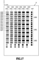
- Fig. 17 is an overall view of an adjustment pattern to be used in the print position adjustment mode of the present embodiment.
- the adjustment pattern of the present embodiment also includes a first pattern 1950 for adjusting the print positions in the outward and return scans, a second pattern 1951 for adjusting the print positions of the ejection port arrays of the same color, and a third pattern 1952 for adjusting the print positions of the ejection port arrays of the different colors. Then, all of these patterns are printed on one print medium P in A4 size.
- a difference of the adjustment pattern in the present embodiment from that in the first embodiment is a combination of two patches above the same platen rib 1303.
- parches 1901 to 1913 are patches for adjusting the print positions in the outward and return scans for the cyan ink.
- parches 1921 to 1933 are patches for adjusting the print positions in the outward and return scans for the light cyan ink.
- two patches arranged above the same platen rib 1303 are patches printed by different colors, that is, by different ejection port arrays. The same applies to the second pattern 1951 and the third pattern 1952.
- the ejection port arrays can be driven at more dispersed locations in the print medium P than in the first embodiment. This makes it possible to print the adjustment pattern while maintaining the stable ejection conditions of the respective ejection port arrays, and thereby to further enhance the adjustment accuracy.
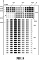
- Fig. 18 is an overall view of an adjustment pattern to be used in the print position adjustment mode of the present embodiment.
- the adjustment pattern in the present embodiment includes a coarse adjustment pattern 2000 in addition to the first pattern 1800, the second pattern 1801, and the third pattern 1802 described in the first embodiment. Then, all of these patterns are printed on one print medium P in A4 size.
- the coarse adjustment pattern 2000 is printed at the head in the conveyance direction (Y direction) prior to the first to third patterns 1800 to 1802 for fine adjustment. Then, before printing of the first to third patterns 1800 to 1802, the coarse adjustment pattern 2000 is read, and a range of the dot shift amount (ejection timing) is set for the multiple patches to be printed in the first to third patterns.
- Fig. 19 is a flowchart for explaining steps in processing in the print position adjustment mode of the present embodiment. Hereinafter the steps will be described with reference to the adjustment pattern in Fig. 18 .
- the CPU 901 Upon start of this processing, the CPU 901 first prints the coarse adjustment pattern 2000 on a print medium P at S11. As illustrated in Fig. 18 , the coarse adjustment pattern 2000 is printed at the head of the print medium P in the conveyance direction (Y direction).
- the coarse adjustment pattern 2000 includes pattern groups 2001 to 2006 for the respective inks of six colors.
- Each of the pattern groups 2001 to 2006 includes five columns and three rows of patches.
- the pattern groups 2001 to 2006 are arranged at equal intervals in the X direction irrespective of the positions of the platen ribs 1303.
- the pattern group 2001 for the cyan ink is focused.
- the five patches in the patch row 2007 are printed by the ejection port array C1 (see Fig. 4 ) in the outward scan.
- the five patches in the patch row 2008 are printed by the ejection port array C1 in the return scan.
- the five patches in the patch row 2009 are printed by the ejection port array C2 in the outward scan.
- the CPU 901 performs processing of reading the patches included in the coarse adjustment pattern 2000 by using the reflection-type optical sensor 130. Specifically, the CPU 901 conveys the print medium P such that the printed coarse adjustment pattern 2000 is located within a region readable by the reflection-type optical sensor 130, and causes the reflection-type optical sensor 130 to perform the reading processing while scanning the carriage 102.
- the CPU 901 sets median adjustment values for the fine adjustment pattern based on the image read at S12.
- the median adjustment value is a value equivalent to a median value of the print positions in the 13 patches for the same adjustment item in the fine adjustment pattern. Specifically, an average value of the amounts of misalignment between the edge positions of the patches in the patch row 2007 in the X direction and the edge positions of the patches in the patch row 2008 in the X direction is obtained. Then, the print position in the outward and return scans for correcting this amount of misalignment is set as the median adjustment value for cyan in the first pattern 1800.
- the CPU 901 sets the median adjustment values for the second pattern 1801 based on the edge positions in the patch row 2007 and the patch row 2008. Further, the CPU 901 sets the median adjustment values for the third pattern 1802 based on the edge positions of the patch groups of the different colors.
- the CPU 901 prints the adjustment pattern for fine adjustment, that is, the first pattern 1800, the second pattern 1801, and the third pattern 1802 based on the median adjustment values set at S13.
- the CPU 901 measures the optical density of each of the patches included in the first pattern 1800, the second pattern 1801, and the third pattern 1802 by using the reflection-type optical sensor 130.
- the CPU 901 determines the adjustment value of the print position for each of the aforementioned items based on the optical densities of the patches obtained at S15.
- the CPU 901 stores the adjustment values determined at S16 in the ROM 902 in association with the respective adjustment items. This processing is completed at the end of this step.
- the adjustment values stored at S17 are used afterwards to print actual images and enable the printing apparatus 1 to output images without print position misalignment.
- the execution of the coarse adjustment processing prior to the fine adjustment processing as in the present embodiment makes it possible to reduce the adjustment range, that is, the number of patches actually printed on a print medium in the fine adjustment processing. For this reason, even if a print head having a large variation of the print position misalignment is used, the print positions can be adjusted appropriately only by printing a predetermined number of patches.
- the adjustment pattern in the first embodiment described with reference to Fig. 16 is used above for the fine adjustment processing
- the adjustment pattern for fine adjustment may be the adjustment pattern in the second embodiment described with reference to Fig. 17 as a matter of course.
- the patches in the present embodiment are arranged at positions that can coincide with the sampling cycles of the reflection-type optical sensor 130 while satisfying the condition that the positions should be within the 6 mm areas on both sides.
- Figs. 20A and 20B are diagrams for comparing the print positions of the patches in the present embodiment with the print positions in the aforementioned embodiments.
- Fig. 20A illustrates the patch print positions without consideration of the sampling cycles and
- Fig. 20B illustrates the patch print positions in the present embodiment in consideration of the sampling cycles.
- Figs. 20A and 20B illustrate enlarged views of the platen ribs 1303 of R6 and R7 and patches 1404 to 1407 printed around these platen ribs 1303.
- FIG. 20B indicates sampling timings 2200 of the reflection-type optical sensor 130 that moves in the X direction at a predetermined velocity.
- a region where the reflection-type optical sensor 130 moves within a period of pulse application is each of sampling sections 2201 to 2206.
- the spot diameter of the reflection-type optical sensor 130 moves from 2207 to 2208, and this movement region is a sampling region.
- the spot diameter of the reflection-type optical sensor 130 moves from 2209 to 2210, and this movement region is a sampling region.
- the sampling regions in the sampling section 2201 and the sampling section 2202 are located at positions approximately symmetric with respect to the platen rib 1303 of R6.
- the sampling cycles of the reflection-type optical sensor 130 are not synchronized with the positions where the platen ribs 1303 are arranged.
- the sampling regions in the sampling section 2205 and the sampling section 2206 are not located at positions symmetric with respect to the platen rib 1303 of R7.
- Fig. 20A in which two patches are printed symmetrically in the right-left direction with respect to each platen rib 1303 without consideration of the sampling cycles, the sampling regions protrude from the patches. In this case, the detection accuracy of the reflection-type optical sensor 130 may decrease.
- the sampling timings of the reflection-type optical sensor 130 may not be set in fixed cycles but may be set according to the positions where the platen ribs 1303 are arranged. In this case, however, a new electric circuit, memory capacity, and firmware processing time are required, which causes an increase in cost.
- each of the patches is shifted to a position including the sampling region with a limitation of the 6 mm area on either side of the corresponding platen rib 1303 while the sampling cycles of the reflection-type optical sensor 130 are kept constant.
- two patches 1406 and 1407 in the vicinity of the platen rib 1303 of R7 are arranged to include the sampling regions in the two sampling sections 2205 and 2206 closest to the platen rib 1303 of R7.
- the two patches 1406 and 1407 are not arranged symmetric with respect to the platen rib 1303 of R7, but are shifted to the right by approximately 0.2 mm with respect to the platen rib 1303. Even in such a situation, the two patches are confined to the 6 mm areas on both sides of the platen rib 1303. Thus, it is possible to perform the print position adjustment mode with high accuracy while keeping the variation of the head-to-paper distance within 100 ⁇ m.
- a degree of unevenness on a print medium P varies depending on various conditions such as the type of the print medium, an environment temperature, and an environment humidity.
- an area where the patch can be arranged is not limited to the 6 mm area from the platen rib 1303 but is also adjustable depending on the above conditions.
- the present embodiment intends to change the number of patches arranged in the vicinity of the platen rib 1303 in the adjustment pattern as appropriate.
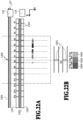
- Figs. 21A to 21C are diagrams for explaining processing of setting the number of patches.
- N same test patches are printed above one platen rib 1303 and on both sides of this platen rib 1303 as illustrated in Fig. 21A .
- the N test patches are the same as the patch described with reference to Fig. 8 , and are printed according to the adjustment value set at this time point.
- Fig. 21B is a top view of the N test patches.
- N is 5 and the test patches 1 to 5 are illustrated.
- the optical density of each of the test patches is measured by using the reflection-type optical sensor 130.
- the optical densities as illustrated in Fig. 21C are obtained.
- the test patch 3 above the platen rib 1303 where no print position misalignment occurs has the highest density, and the density of the test patch becomes lower as the distance from the platen rib 1303 increases.
- a density difference ⁇ D corresponding to a tolerable range of print position misalignment is determined in advance and patches can be printed only at positions corresponding to test patches each having a density difference ⁇ D or less in the actual print position adjustment mode.
- patches can be arranged at three areas corresponding to the test patches 2 to 4.
- Figs. 22A and 22B are diagrams illustrating how patches are printed in the X direction in the print position adjustment mode of the present embodiment.
- Fig. 22A depicts an overall view in the X direction and
- Fig. 22B depicts an enlarged view of an area around the platen rib 1303 of R4.
- an adjustment pattern for adjusting the print positions in the outward scan and the print positions in the return scan by using a print medium Pin A4 size is illustrated as an example.
- three patches 2401 to 2403 each having a width of 4.7 mm are arranged next to each other with the platen rib 1303 centered.
- the positions of these three patches are included in an area around the position of the platen rib 1303 where the print position misalignment due to the variation of the head-to-paper distance is confirmed sufficiently small. Therefore, the print position misalignment is within the tolerable range, and the favorable print position adjustment can be performed.
- the width in the X direction for printing the same numbers of patches is narrower than in the adjustment pattern in Fig. 15A .
- the movement range of the carriage is narrower than in the case of using the adjustment pattern in Fig. 15A , so that the mode itself can be completed within a shorter time.
- the patches are shifted as a whole to the center (the left side in Fig. 22A ) in the adjustment pattern in Fig. 22A , a print medium in a size smaller than A4 can be used. This also makes it possible to further save consumption of print media.
- the description is given on the assumption that the print medium P in A4 size is used. Instead, needless to say, the adjustment patterns described in the above embodiments may be also printed on print media larger than the A4 size.
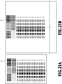
- Figs. 23A and 23B are diagrams illustrating cases where the pattern in Fig. 18 is printed on a print medium P in A4 size and a print medium P' in A3 size.
- an alternate long and short dash line corresponds to an area supported by the platen rib 1303 of R7 in the course of conveying a print medium P.
- the printing apparatus 1 in the above embodiments conveys a print medium P with the center of the print medium P aligned with the center line 1305 of the printable region W irrespective of the size of the print medium used. For this reason, in the print position adjustment mode, the relative positional relation between the patches included in the adjustment pattern and the platen ribs 1303 is stable irrespective of the size of a print medium. In sum, use of a print medium in a predetermined size or larger in the print position adjustment mode makes it possible to perform stable print position adjustment while avoiding a variation of the adjustment accuracy.
- Embodiment(s) of the present invention can also be realized by a computer of a system or apparatus that reads out and executes computer executable instructions (e.g., one or more programs) recorded on a storage medium (which may also be referred to more fully as a 'non-transitory computer-readable storage medium') to perform the functions of one or more of the above-described embodiment(s) and/or that includes one or more circuits (e.g., application specific integrated circuit (ASIC)) for performing the functions of one or more of the above-described embodiment(s), and by a method performed by the computer of the system or apparatus by, for example, reading out and executing the computer executable instructions from the storage medium to perform the functions of one or more of the above-described embodiment(s) and/or controlling the one or more circuits to perform the functions of one or more of the above-described embodiment(s).
- computer executable instructions e.g., one or more programs
- a storage medium which may also be referred to more fully as
- the computer may comprise one or more processors (e.g., central processing unit (CPU), micro processing unit (MPU)) and may include a network of separate computers or separate processors to read out and execute the computer executable instructions.
- the computer executable instructions may be provided to the computer, for example, from a network or the storage medium.
- the storage medium may include, for example, one or more of a hard disk, a random-access memory (RAM), a read only memory (ROM), a storage of distributed computing systems, an optical disk (such as a compact disc (CD), digital versatile disc (DVD), or Blu-ray Disc (BD) TM ), a flash memory device, a memory card, and the like.
Landscapes
- Engineering & Computer Science (AREA)
- Quality & Reliability (AREA)
- Multimedia (AREA)
- Signal Processing (AREA)
- General Engineering & Computer Science (AREA)
- Physics & Mathematics (AREA)
- General Physics & Mathematics (AREA)
- Theoretical Computer Science (AREA)
- Ink Jet (AREA)
Claims (23)
- Druckvorrichtung (1), umfassend:einen Schlitten (102), der sich in einer Abtastrichtung (X) hin- und herbewegen kann;eine Druckeinrichtung (202), die auf dem Schlitten montiert ist und mehrere Druckelemente (500) enthält, zum Erzeugen von Punkten auf einem Druckmedium (P) durch Aufbringen von Tintentröpfchen (550), während der Schlitten in der Abtastrichtung (X) bewegt wird;ein Transportelement (961), das konfiguriert ist, ein Druckmedium (P) in einer die Abtastrichtung kreuzenden Transportrichtung (Y) zu transportieren;mehrere Plattenrippen (1303), die konfiguriert sind, auf einer Transportstrecke eines Druckmediums (P) an Positionen in vorbestimmten Abständen in der Abtastrichtung und der Druckeinrichtung (202) zugewandt angeordnet zu sein und das Druckmedium (P) zu tragen,einen optischen Sensor vom Reflexionstyp (130), der konfiguriert ist, durch den Schlitten in der Abtastrichtung bewegbar zu sein und ein Bild auf dem Druckmedium (P) zu lesen,eine Steuerung (900), die konfiguriert ist, die Druckeinrichtung (202) zu steuern,wobei die Druckeinrichtung (202) konfiguriert ist, ansprechend auf Empfangen einer Anweisung zum Justieren von Druckpositionen von Tintentröpfchen, die durch die Druckeinrichtung (202) aufgebracht werden sollen, ein Justierungsmuster auf ein Druckmedium (P) zu drucken, wobei das Justierungsmuster mehrere erste Felder enthält und zur Justierung verwendet wird,die Druckeinrichtung (202) ferner konfiguriert ist, das Justierungsmuster derart zu drucken, dass zwei oder mehr Felder in der Abtastrichtung nebeneinander in einem benachbarten Gebiet um eine bestimmte der mehreren Plattenrippen (1303) gedruckt werden und dass keine Felder in einem mittleren Gebiet in der Abtastrichtung zwischen der bestimmten Plattenrippe (1303) und einer anderen Plattenrippe (1303) neben der bestimmten Plattenrippe (1303) gedruckt werden,dadurch gekennzeichnet, dassdie Druckeinrichtung (202) vor dem Drucken des Justierungsmusters ein grobes Justierungsmuster (2000) zum Justieren von Druckpositionen der Punkte mit einer gröberen Genauigkeit als derjenigen des Justierungsmusters druckt, wobei mehrere zweite Felder, die in dem groben Justierungsmuster (2000) enthalten sind, unabhängig von den Positionen der mehreren Plattenrippen (1303) angeordnet sind, unddie Steuerung (900) unter Verwendung des optischen Sensors vom Reflexionstyp (130) ein Leseergebnis des groben Justierungsmusters (2000) erhält und die Druckeinrichtung (202) steuert, die Druckpositionen der Punkte in den mehreren ersten Feldern im Justierungsmuster basierend auf dem Leseergebnis zu ändern.
- Druckvorrichtung nach Anspruch 1, wobei
das benachbarte Gebiet ein Gebiet ist, in dem eine Variation eines Abstands zwischen der Druckeinrichtung und dem Druckmedium in einem Zustand, in dem die Druckeinrichtung dem Druckmedium zugewandt ist, innerhalb eines vorbestimmten Bereichs liegt. - Druckvorrichtung nach Anspruch 2, wobei
ein oberer Grenzwert des vorbestimmten Bereichs die Hälfte einer maximalen Variation des Abstands zwischen der Druckeinrichtung und dem Druckmedium ist. - Druckvorrichtung (1), umfassend:einen Schlitten (102), der sich in einer Abtastrichtung (X) hin- und herbewegen kann;eine Druckeinrichtung (202), die auf dem Schlitten montiert ist und mehrere Druckelemente (500) enthält, zum Erzeugen von Punkten auf einem Druckmedium (P) durch Aufbringen von Tintentröpfchen (550), während der Schlitten in der Abtastrichtung (X) bewegt wird;ein Transportelement (961), das konfiguriert ist, ein Druckmedium (P) in einer die Abtastrichtung kreuzenden Transportrichtung (Y) zu transportieren;mehrere Plattenrippen (1303), die konfiguriert sind, auf einer Transportstrecke eines Druckmediums (P) an Positionen in vorbestimmten Abständen in der Abtastrichtung und der Druckeinrichtung (202) zugewandt angeordnet zu sein und das Druckmedium (P) zu tragen; undeinen optischen Sensor vom Reflexionstyp (130), der konfiguriert ist, durch den Schlitten in der Abtastrichtung bewegbar zu sein und ein Bild auf dem Druckmedium (P) zu lesen,wobei die Druckeinrichtung (202) konfiguriert ist, ansprechend auf Empfangen einer Anweisung zum Justieren von Druckpositionen von Tintentröpfchen, die durch die Druckeinrichtung (202) aufgebracht werden sollen, ein Justierungsmuster auf ein Druckmedium (P) zu drucken, wobei das Justierungsmuster mehrere erste Felder enthält und zur Justierung verwendet wird, unddie Druckeinrichtung (202) ferner konfiguriert ist, das Justierungsmuster derart zu drucken, dass zwei oder mehr Felder in der Abtastrichtung nebeneinander in einem benachbarten Gebiet um eine bestimmte der mehreren Plattenrippen (1303) gedruckt werden und dass keine Felder in einem mittleren Gebiet zwischen der bestimmten Plattenrippe (1303) und einer anderen Plattenrippe (1303) neben der bestimmten Plattenrippe (1303) in der Abtastrichtung gedruckt werden;dadurch gekennzeichnet, dassdie Druckeinrichtung vor dem Drucken des Justierungsmusters mehrere gleiche Testfelder in der Abtastrichtung nebeneinander oberhalb und auf beiden Seiten der bestimmten Plattenrippe druckt;der optische Sensor vom Reflexionstyp konfiguriert ist, eine optische Dichte (D) eines jeweiligen der Testfelder zu messen; unddie Druckvorrichtung konfiguriert ist, Testfelder zu bestimmen, die jeweils eine Differenz optischer Dichte (ΔD) oder weniger in Bezug auf eine höchste gemessene optische Dichte der Testfelder aufweisen, und die Anzahl der zwei oder mehr Felder im Justierungsmuster derart zu ändern, dass Felder durch die Druckeinrichtung in dem benachbarten Gebiet nur an Positionen gedruckt werden, die den Testfeldern entsprechen, die jeweils die Differenz optischer Dichte oder weniger aufweisen.
- Druckvorrichtung nach einem der Ansprüche 1 bis 4, wobeidie mehreren ersten Felder jeweils eine erste Punktgruppe (1000) und eine zweite Punktgruppe (1001) enthalten, undsich die mehreren ersten Felder in Bezug auf relative Druckpositionen der ersten Punktgruppe und der zweiten Punktgruppe voneinander unterscheiden.
- Druckvorrichtung nach Anspruch 5, wobei die Druckeinheit konfiguriert ist, die erste Punktgruppe in einer Vorwärtsabtastung zu drucken, in der die Druckeinrichtung sich in der Abtastrichtung bewegt, und konfiguriert ist, die zweite Punktgruppe in einer Rückwärtsabtastung zu drucken, in der die Druckeinrichtung sich in einer entgegengesetzt der Abtastrichtung verlaufenden Richtung (-X) bewegt.
- Druckvorrichtung nach Anspruch 5, wobeidie Druckeinrichtung enthält: eine erste Ausstoßöffnungsanordnung (501), in der Ausstoßöffnungen (500), die eine erste Tinte ausstoßen, in der Transportrichtung angeordnet sind, und eine zweite Ausstoßöffnungsanordnung (502), in der Ausstoßöffnungen (500), die die erste Tinte ausstoßen, in der Transportrichtung angeordnet sind, wobei die zweite Ausstoßöffnungsanordnung die erste Ausstoßöffnungsanordnung in der Abtastrichtung gesehen überlappt, unddie Druckeinrichtung konfiguriert ist, die erste Punktgruppe unter Verwendung der ersten Ausstoßöffnungsanordnung zu drucken, und konfiguriert ist, die zweite Punktgruppe unter Verwendung der zweiten Ausstoßöffnungsanordnung zu drucken.
- Druckvorrichtung nach Anspruch 5, wobeidie Druckeinrichtung enthält: eine erste Ausstoßöffnungsanordnung (501), in der Ausstoßöffnungen (500), die eine erste Tinte ausstoßen, in der Transportrichtung angeordnet sind, und eine zweite Ausstoßöffnungsanordnung (501), in der Ausstoßöffnungen (500), die eine von der ersten Tinte verschiedene zweite Tinte ausstoßen, in der Transportrichtung angeordnet sind, wobei die zweite Ausstoßöffnungsanordnung die erste Ausstoßöffnungsanordnung in der Abtastrichtung gesehen überlappt, unddie Druckeinrichtung konfiguriert ist, die erste Punktgruppe unter Verwendung der ersten Ausstoßöffnungsanordnung zu drucken, und konfiguriert ist, die zweite Punktgruppe unter Verwendung der zweiten Ausstoßöffnungsanordnung zu drucken.
- Druckvorrichtung nach Anspruch 5, wobeidie Druckeinrichtung enthält: eine erste Ausstoßöffnungsanordnung (501), in der Ausstoßöffnungen (500), die eine erste Tinte ausstoßen, in der Transportrichtung angeordnet sind, eine zweite Ausstoßöffnungsanordnung (501), in der Ausstoßöffnungen (500), die die erste Tinte ausstoßen, in der Transportrichtung angeordnet sind, wobei die zweite Ausstoßöffnungsanordnung die erste Ausstoßöffnungsanordnung in der Abtastrichtung gesehen überlappt, und eine dritte Ausstoßöffnungsanordnung, in der Ausstoßöffnungen, die eine von der ersten Tinte verschiedene zweite Tinte ausstoßen, in der Transportrichtung angeordnet sind, wobei die dritte Ausstoßöffnungsanordnung die erste Ausstoßöffnungsanordnung in der Abtastrichtung gesehen überlappt, unddie Druckeinrichtung konfiguriert ist zum Drucken, auf dasselbe Druckmedium,eines ersten Musters, in dem die erste Punktgruppe in einer Vorwärtsabtastung gedruckt wird, in der die Druckeinrichtung sich in der Abtastrichtung bewegt, und die zweite Punktgruppe in einer Rückwärtsabtastung gedruckt wird, in der die Druckeinrichtung sich in einer entgegengesetzt der Abtastrichtung verlaufenden Richtung (-X) bewegt,eines zweiten Musters, in dem die erste Punktgruppe durch die erste Ausstoßöffnungsanordnung gedruckt wird und die zweite Punktgruppe durch die zweite Ausstoßöffnungsanordnung gedruckt wird, undeines dritten Musters, in dem die erste Punktgruppe durch die erste Ausstoßöffnungsanordnung gedruckt wird und die zweite Punktgruppe durch die dritte Ausstoßöffnungsanordnung gedruckt wird.
- Druckvorrichtung nach einem der Ansprüche 1 bis 9, wobeider optische Sensor vom Reflexionstyp (130) konfiguriert ist, eine optische Dichte eines jeweiligen der mehreren ersten Felder während des Abtastens in der Abtastrichtung zu erfassen; und ferner umfassendeine Einstelleinheit (901), die konfiguriert ist, einen Justierungswert einer Druckposition eines jeweiligen Tintentröpfchens, das durch die Druckeinrichtung zum Drucken eines tatsächlichen Bilds aufgebracht werden soll, basierend auf den durch die Erfassungseinheit erfassten optischen Dichten der mehreren ersten Felder einzustellen.
- Druckvorrichtung nach Anspruch 10, wobei die Einstelleinheit konfiguriert ist, als den Justierungswert die Druckposition des durch die Druckeinrichtung aufgebrachten Tintentröpfchens für das Feld mit der höchsten optischen Dichte von den mehreren ersten Feldern einzustellen.
- Druckvorrichtung nach Anspruch 10 oder 11, wobei die Druckeinrichtung konfiguriert ist, einen Satz von zwei oder mehr Feldern entsprechend einer Plattenrippe in Übereinstimmung mit einem Abtastzyklus der Erfassungseinheit in der Abtastrichtung zu drucken.
- Druckvorrichtung nach einem der Ansprüche 1 bis 12, wobei Felder in einem Satz der zwei oder mehr Felder entsprechend einer Plattenrippe unter Verwendung derselben Ausstoßöffnungsanordnung der Druckeinrichtung gedruckt werden.
- Druckvorrichtung nach einem der Ansprüche 1 bis 12, wobei Felder in einem Satz der zwei oder mehr Felder entsprechend einer Plattenrippe unter Verwendung verschiedener Ausstoßöffnungsanordnungen der Druckeinrichtung gedruckt werden.
- Druckvorrichtung nach einem der Ansprüche 1 bis 14, wobei das mittlere Gebiet eine Mittelposition zwischen der bestimmten Plattenrippe und der anderen Plattenrippe enthält.
- Druckvorrichtung nach einem der Ansprüche 1 bis 15, wobeiein Feld auf einer Seite der bestimmten Plattenrippe in der Abtastrichtung gedruckt wird, undein anderes Feld auf der anderen Seite der bestimmten Plattenrippe in der Abtastrichtung gedruckt wird.
- Druckvorrichtung nach einem der Ansprüche 1 bis 16, wobeimindestens ein Teil eines Felds auf einer Seite der bestimmten Plattenrippe in der Abtastrichtung gedruckt wird, undmindestens ein Teil eines anderen Felds auf der anderen Seite der bestimmten Plattenrippe in der Abtastrichtung gedruckt wird.
- Druckvorrichtung nach einem der Ansprüche 1 bis 17, wobei die mehreren Plattenrippen in der Abtastrichtung symmetrisch in Bezug auf eine Mittellinie (1305) einer durch die Druckeinrichtung bedruckbaren Region angeordnet sind.
- Druckvorrichtung nach einem der Ansprüche 1 bis 18, wobei die Druckeinrichtung konfiguriert ist, die zwei oder mehr Felder nebeneinander innerhalb von Gebieten von 6 mm auf beiden Seiten der bestimmten Plattenrippe zu drucken.
- Druckvorrichtung nach einem der Ansprüche 1 bis 19, wobei die Druckeinrichtung konfiguriert ist, die zwei oder mehr Felder an in Bezug auf die bestimmte Plattenrippe symmetrischen Positionen zu drucken.
- Druckvorrichtung nach einem der Ansprüche 1 bis 19, wobei die Druckeinrichtung konfiguriert ist, eine Positionsbeziehung in der Abtastrichtung zwischen den mehreren Plattenrippen und den mehreren ersten Feldern unabhängig von einer Größe des Druckmediums konstant zu halten.
- Druckverfahren für eine Druckvorrichtung (1), umfassend einen Schlitten (102), eine Druckeinrichtung (202), ein Transportelement (961), mehrere Plattenrippen (1303), einen optischen Sensor vom Reflexionstyp (130) und eine Steuerung,
wobeider Schlitten (102) sich in einer Abtastrichtung (X) hin- und herbewegen kann;die Druckeinrichtung (202) auf dem Schlitten montiert ist und konfiguriert ist, durch Aufbringen von Tintentröpfchen (550), während sie sich in der Abtastrichtung (X) bewegt, Punkte auf einem Druckmedium (P) zu erzeugen,das Transportelement (961) konfiguriert ist, ein Druckmedium (P) in einer die Abtastrichtung kreuzenden Transportrichtung (Y) zu transportieren, unddie mehreren Plattenrippen (1303) auf einer Transportstrecke eines Druckmediums (P) an Positionen in vorbestimmten Abständen in der Abtastrichtung und der Druckeinrichtung (202) zugewandt angeordnet sind und konfiguriert sind, das Druckmedium (P) zu tragen,der optische Sensor vom Reflexionstyp (130) konfiguriert ist, durch den Schlitten in der Abtastrichtung bewegbar zu sein und ein Bild auf dem Druckmedium (P) zu lesen,die Steuerung (900) die Druckeinrichtung (202) steuert,wobei das Druckverfahren umfasst:einen Empfangsschritt zum Empfangen einer Anweisung zum Justieren von Druckpositionen von Tintentröpfchen (550), die durch die Druckeinrichtung aufgebracht werden sollen, undeinen Druckschritt (S1, S11, S14) zum Drucken eines Justierungsmusters, das mehrere erste Felder enthält und zum Justieren verwendet wird,wobei das Justierungsmuster derart gedruckt wird, dass zwei oder mehr Felder in der Abtastrichtung nebeneinander in einem benachbarten Gebiet um eine bestimmte der mehreren Plattenrippen (1303) gedruckt werden und dass keine Felder in einem mittleren Gebiet in der Abtastrichtung zwischen der bestimmten Plattenrippe (1303) und einer anderen Plattenrippe (1303) neben der bestimmten Plattenrippe (1303) gedruckt werden,dadurch gekennzeichnet, dassim Druckschritt (S1, S11, S14) vor dem Drucken des Justierungsmusters ein grobes Justierungsmuster (2000) zum Justieren von Druckpositionen der Punkte mit einer gröberen Genauigkeit als derjenigen des Justierungsmusters gedruckt wird, wobei mehrere zweite Felder, die in dem groben Justierungsmuster (2000) enthalten sind, unabhängig von den Positionen der mehreren Plattenrippen (1303) angeordnet sind,der optische Sensor vom Reflexionstyp (130) das grobe Justierungsmuster (2000) liest unddie Druckpositionen der Punkte in den mehreren ersten Feldern im Justierungsmuster basierend auf dem Leseergebnis geändert werden. - Druckverfahren für eine Druckvorrichtung (1), umfassend einen Schlitten (102), eine Druckeinrichtung (202), ein Transportelement (961), mehrere Plattenrippen (1303) und einen optischen Sensor vom Reflexionstyp (130),
wobeider Schlitten (102) sich in einer Abtastrichtung (X) hin- und herbewegen kann;die Druckeinrichtung (202) auf dem Schlitten montiert ist und konfiguriert ist, durch Aufbringen von Tintentröpfchen (550) während dem Abtasten in der Abtastrichtung (X) Punkte auf einem Druckmedium (P) zu erzeugen,das Transportelement (961) konfiguriert ist, ein Druckmedium (P) in einer die Abtastrichtung kreuzenden Transportrichtung (Y) zu transportieren,die mehreren Plattenrippen (1303) auf einer Transportstrecke eines Druckmediums (P) an der Druckeinrichtung (202) zugewandten Positionen in vorbestimmten Abständen in der Abtastrichtung angeordnet sind und konfiguriert sind, das Druckmedium (P) zu tragen, undder optische Sensor vom Reflexionstyp (130) konfiguriert ist, durch den Schlitten in der Abtastrichtung bewegbar zu sein und ein Bild auf dem Druckmedium (P) zu lesen;wobei das Druckverfahren umfasst:einen Empfangsschritt zum Empfangen einer Anweisung zum Justieren von Druckpositionen von Tintentröpfchen (550), die durch die Druckeinrichtung aufgebracht werden sollen, undeinen Druckschritt (S1, 511, S14) zum Drucken eines Justierungsmusters, das mehrere erste Felder enthält und zur Justierung verwendet wird,wobei das Justierungsmuster derart gedruckt wird, dass zwei oder mehr Felder in der Abtastrichtung in einem benachbarten Gebiet um eine bestimmte der mehreren Plattenrippen (1303) nebeneinander gedruckt werden und dass keine Felder in einem mittleren Gebiet in der Abtastrichtung zwischen der bestimmten Plattenrippe (1303) und einer anderen Plattenrippe (1303) neben der bestimmten Plattenrippe (1303) gedruckt werden,dadurch gekennzeichnet, dassvor dem Druckschritt zum Drucken des Justierungsmusters mehrere gleiche Testfelder in der Abtastrichtung nebeneinander oberhalb und auf beiden Seiten der bestimmten Plattenrippe gedruckt werden,eine optische Dichte (D) eines jeweiligen der Testfelder mit dem optischen Sensor vom Reflexionstyp gemessen wird, undTestfelder bestimmt werden, die jeweils eine Differenz optischer Dichte (ΔD) oder weniger in Bezug auf eine höchste gemessene optische Dichte der Testfelder aufweisen, und die Anzahl der zwei oder mehr Felder im Justierungsmuster derart geändert wird, dass Felder in dem benachbarten Gebiet nur an Positionen gedruckt werden, die den Testfeldern entsprechen, die jeweils die Differenz optischer Dichte oder weniger aufweisen.
Applications Claiming Priority (1)
| Application Number | Priority Date | Filing Date | Title |
|---|---|---|---|
| JP2019236668A JP7433900B2 (ja) | 2019-12-26 | 2019-12-26 | インクジェット記録装置および調整パターン記録方法 |
Publications (2)
| Publication Number | Publication Date |
|---|---|
| EP3842239A1 EP3842239A1 (de) | 2021-06-30 |
| EP3842239B1 true EP3842239B1 (de) | 2024-05-01 |
Family
ID=73855157
Family Applications (1)
| Application Number | Title | Priority Date | Filing Date |
|---|---|---|---|
| EP20214705.4A Active EP3842239B1 (de) | 2019-12-26 | 2020-12-16 | Tintenstrahldruckvorrichtung und anpassungsmusterdruckverfahren |
Country Status (3)
| Country | Link |
|---|---|
| US (1) | US11577524B2 (de) |
| EP (1) | EP3842239B1 (de) |
| JP (1) | JP7433900B2 (de) |
Families Citing this family (1)
| Publication number | Priority date | Publication date | Assignee | Title |
|---|---|---|---|---|
| JP7632032B2 (ja) * | 2021-04-28 | 2025-02-19 | ブラザー工業株式会社 | 液滴吐出装置 |
Family Cites Families (8)
| Publication number | Priority date | Publication date | Assignee | Title |
|---|---|---|---|---|
| JP5063327B2 (ja) | 2007-12-14 | 2012-10-31 | キヤノン株式会社 | インクジェット記録装置および調整値取得方法 |
| JP2010143123A (ja) | 2008-12-19 | 2010-07-01 | Canon Inc | 記録装置および記録方法 |
| JP4894881B2 (ja) | 2009-04-27 | 2012-03-14 | セイコーエプソン株式会社 | 液体吐出装置 |
| JP5287819B2 (ja) | 2010-10-06 | 2013-09-11 | ブラザー工業株式会社 | インクジェット記録装置 |
| JP6298229B2 (ja) | 2011-12-27 | 2018-03-20 | ブラザー工業株式会社 | 印刷データ生成装置、および、コンピュータプログラム |
| EP2684700B1 (de) * | 2012-07-09 | 2015-08-12 | Brother Kogyo Kabushiki Kaisha | Verfahren zum Formen eines Tintenausgabeeinstellmusters, Tintenausgabeeinstellverfahren für Tintenstrahlkopf und Tintenstrahldrucker |
| JP6111542B2 (ja) | 2012-07-09 | 2017-04-12 | ブラザー工業株式会社 | 吐出調整パターン形成方法、インクジェットヘッドの吐出調整方法、及び、インクジェットプリンタ |
| JP5705291B2 (ja) | 2013-11-08 | 2015-04-22 | キヤノン株式会社 | 記録装置 |
-
2019
- 2019-12-26 JP JP2019236668A patent/JP7433900B2/ja active Active
-
2020
- 2020-12-16 EP EP20214705.4A patent/EP3842239B1/de active Active
- 2020-12-17 US US17/125,637 patent/US11577524B2/en active Active
Also Published As
| Publication number | Publication date |
|---|---|
| JP7433900B2 (ja) | 2024-02-20 |
| US11577524B2 (en) | 2023-02-14 |
| US20210197579A1 (en) | 2021-07-01 |
| EP3842239A1 (de) | 2021-06-30 |
| JP2021104614A (ja) | 2021-07-26 |
Similar Documents
| Publication | Publication Date | Title |
|---|---|---|
| US11292268B2 (en) | Printing apparatus, registration adjustment method, and storage medium | |
| US7637586B2 (en) | Array type inkjet printer and method for determining condition of nozzles thereof | |
| US9227442B2 (en) | Printing apparatus and registration adjustment method | |
| US8636334B2 (en) | Printing apparatus and adjustment pattern printing method | |
| US11919300B2 (en) | Inkjet printing apparatus and inkjet printing method | |
| US9555620B2 (en) | Printing apparatus and method for adjusting printing position | |
| US7758139B2 (en) | Liquid ejecting apparatus and transport method | |
| US7267419B2 (en) | Method for liquid ejection and liquid ejecting apparatus | |
| US20200039248A1 (en) | Printing apparatus and printing method | |
| US9308741B2 (en) | Printing apparatus and printing method | |
| EP3842239B1 (de) | Tintenstrahldruckvorrichtung und anpassungsmusterdruckverfahren | |
| JP2010030161A (ja) | 画像形成装置 | |
| US11345176B2 (en) | Recording apparatus, control method, and storage medium | |
| US9840087B2 (en) | Liquid ejecting apparatus and liquid ejecting method | |
| JP2009056719A (ja) | 液体吐出装置およびその制御方法並びにプログラム | |
| EP1525988A1 (de) | Verfahren und Vorrichtung zum Betreiben eines Druckers | |
| JP5705291B2 (ja) | 記録装置 | |
| JP5101416B2 (ja) | 画像形成装置 | |
| JP2009119751A (ja) | インクジェット記録装置及びその装置に用いる記録制御方法 | |
| JP4419471B2 (ja) | 液体吐出装置、及び液体吐出方法 | |
| JP2020032702A (ja) | インクジェット記録装置、インクジェット記録装置のための制御方法、及びプログラム | |
| JP2005074853A (ja) | 印刷装置、印刷方法、ドット形成方法、プログラム及び印刷システム | |
| JP2023122009A (ja) | プリンタ | |
| JP2010143123A (ja) | 記録装置および記録方法 | |
| JP2014019101A (ja) | インクジェット記録装置 |
Legal Events
| Date | Code | Title | Description |
|---|---|---|---|
| PUAI | Public reference made under article 153(3) epc to a published international application that has entered the european phase |
Free format text: ORIGINAL CODE: 0009012 |
|
| STAA | Information on the status of an ep patent application or granted ep patent |
Free format text: STATUS: THE APPLICATION HAS BEEN PUBLISHED |
|
| AK | Designated contracting states |
Kind code of ref document: A1 Designated state(s): AL AT BE BG CH CY CZ DE DK EE ES FI FR GB GR HR HU IE IS IT LI LT LU LV MC MK MT NL NO PL PT RO RS SE SI SK SM TR |
|
| STAA | Information on the status of an ep patent application or granted ep patent |
Free format text: STATUS: REQUEST FOR EXAMINATION WAS MADE |
|
| 17P | Request for examination filed |
Effective date: 20220103 |
|
| RBV | Designated contracting states (corrected) |
Designated state(s): AL AT BE BG CH CY CZ DE DK EE ES FI FR GB GR HR HU IE IS IT LI LT LU LV MC MK MT NL NO PL PT RO RS SE SI SK SM TR |
|
| STAA | Information on the status of an ep patent application or granted ep patent |
Free format text: STATUS: EXAMINATION IS IN PROGRESS |
|
| 17Q | First examination report despatched |
Effective date: 20221130 |
|
| REG | Reference to a national code |
Ref country code: DE Ref legal event code: R079 Free format text: PREVIOUS MAIN CLASS: B41J0002165000 Ipc: B41J0002210000 Ref country code: DE Ref legal event code: R079 Ref document number: 602020030038 Country of ref document: DE Free format text: PREVIOUS MAIN CLASS: B41J0002165000 Ipc: B41J0002210000 |
|
| GRAP | Despatch of communication of intention to grant a patent |
Free format text: ORIGINAL CODE: EPIDOSNIGR1 |
|
| STAA | Information on the status of an ep patent application or granted ep patent |
Free format text: STATUS: GRANT OF PATENT IS INTENDED |
|
| RIC1 | Information provided on ipc code assigned before grant |
Ipc: B41J 29/393 20060101ALN20231030BHEP Ipc: H04N 1/60 20060101ALI20231030BHEP Ipc: H04N 1/407 20060101ALI20231030BHEP Ipc: G06K 15/02 20060101ALI20231030BHEP Ipc: B41J 19/14 20060101ALI20231030BHEP Ipc: B41J 11/00 20060101ALI20231030BHEP Ipc: B41J 2/21 20060101AFI20231030BHEP |
|
| INTG | Intention to grant announced |
Effective date: 20231130 |
|
| RIC1 | Information provided on ipc code assigned before grant |
Ipc: B41J 29/393 20060101ALN20231122BHEP Ipc: H04N 1/60 20060101ALI20231122BHEP Ipc: H04N 1/407 20060101ALI20231122BHEP Ipc: G06K 15/02 20060101ALI20231122BHEP Ipc: B41J 19/14 20060101ALI20231122BHEP Ipc: B41J 11/00 20060101ALI20231122BHEP Ipc: B41J 2/21 20060101AFI20231122BHEP |
|
| GRAS | Grant fee paid |
Free format text: ORIGINAL CODE: EPIDOSNIGR3 |
|
| GRAA | (expected) grant |
Free format text: ORIGINAL CODE: 0009210 |
|
| STAA | Information on the status of an ep patent application or granted ep patent |
Free format text: STATUS: THE PATENT HAS BEEN GRANTED |
|
| AK | Designated contracting states |
Kind code of ref document: B1 Designated state(s): AL AT BE BG CH CY CZ DE DK EE ES FI FR GB GR HR HU IE IS IT LI LT LU LV MC MK MT NL NO PL PT RO RS SE SI SK SM TR |
|
| REG | Reference to a national code |
Ref country code: GB Ref legal event code: FG4D |
|
| REG | Reference to a national code |
Ref country code: CH Ref legal event code: EP |
|
| REG | Reference to a national code |
Ref country code: IE Ref legal event code: FG4D |
|
| REG | Reference to a national code |
Ref country code: DE Ref legal event code: R096 Ref document number: 602020030038 Country of ref document: DE |
|
| REG | Reference to a national code |
Ref country code: LT Ref legal event code: MG9D |
|
| REG | Reference to a national code |
Ref country code: NL Ref legal event code: MP Effective date: 20240501 |
|
| PG25 | Lapsed in a contracting state [announced via postgrant information from national office to epo] |
Ref country code: IS Free format text: LAPSE BECAUSE OF FAILURE TO SUBMIT A TRANSLATION OF THE DESCRIPTION OR TO PAY THE FEE WITHIN THE PRESCRIBED TIME-LIMIT Effective date: 20240901 |
|
| PG25 | Lapsed in a contracting state [announced via postgrant information from national office to epo] |
Ref country code: BG Free format text: LAPSE BECAUSE OF FAILURE TO SUBMIT A TRANSLATION OF THE DESCRIPTION OR TO PAY THE FEE WITHIN THE PRESCRIBED TIME-LIMIT Effective date: 20240501 |
|
| PG25 | Lapsed in a contracting state [announced via postgrant information from national office to epo] |
Ref country code: FI Free format text: LAPSE BECAUSE OF FAILURE TO SUBMIT A TRANSLATION OF THE DESCRIPTION OR TO PAY THE FEE WITHIN THE PRESCRIBED TIME-LIMIT Effective date: 20240501 Ref country code: HR Free format text: LAPSE BECAUSE OF FAILURE TO SUBMIT A TRANSLATION OF THE DESCRIPTION OR TO PAY THE FEE WITHIN THE PRESCRIBED TIME-LIMIT Effective date: 20240501 |
|
| PG25 | Lapsed in a contracting state [announced via postgrant information from national office to epo] |
Ref country code: GR Free format text: LAPSE BECAUSE OF FAILURE TO SUBMIT A TRANSLATION OF THE DESCRIPTION OR TO PAY THE FEE WITHIN THE PRESCRIBED TIME-LIMIT Effective date: 20240802 |
|
| PG25 | Lapsed in a contracting state [announced via postgrant information from national office to epo] |
Ref country code: PT Free format text: LAPSE BECAUSE OF FAILURE TO SUBMIT A TRANSLATION OF THE DESCRIPTION OR TO PAY THE FEE WITHIN THE PRESCRIBED TIME-LIMIT Effective date: 20240902 |
|
| REG | Reference to a national code |
Ref country code: AT Ref legal event code: MK05 Ref document number: 1681829 Country of ref document: AT Kind code of ref document: T Effective date: 20240501 |
|
| PG25 | Lapsed in a contracting state [announced via postgrant information from national office to epo] |
Ref country code: NL Free format text: LAPSE BECAUSE OF FAILURE TO SUBMIT A TRANSLATION OF THE DESCRIPTION OR TO PAY THE FEE WITHIN THE PRESCRIBED TIME-LIMIT Effective date: 20240501 |
|
| PG25 | Lapsed in a contracting state [announced via postgrant information from national office to epo] |
Ref country code: ES Free format text: LAPSE BECAUSE OF FAILURE TO SUBMIT A TRANSLATION OF THE DESCRIPTION OR TO PAY THE FEE WITHIN THE PRESCRIBED TIME-LIMIT Effective date: 20240501 |
|
| PG25 | Lapsed in a contracting state [announced via postgrant information from national office to epo] |
Ref country code: AT Free format text: LAPSE BECAUSE OF FAILURE TO SUBMIT A TRANSLATION OF THE DESCRIPTION OR TO PAY THE FEE WITHIN THE PRESCRIBED TIME-LIMIT Effective date: 20240501 |
|
| PG25 | Lapsed in a contracting state [announced via postgrant information from national office to epo] |
Ref country code: PL Free format text: LAPSE BECAUSE OF FAILURE TO SUBMIT A TRANSLATION OF THE DESCRIPTION OR TO PAY THE FEE WITHIN THE PRESCRIBED TIME-LIMIT Effective date: 20240501 |
|
| PG25 | Lapsed in a contracting state [announced via postgrant information from national office to epo] |
Ref country code: LV Free format text: LAPSE BECAUSE OF FAILURE TO SUBMIT A TRANSLATION OF THE DESCRIPTION OR TO PAY THE FEE WITHIN THE PRESCRIBED TIME-LIMIT Effective date: 20240501 |
|
| PG25 | Lapsed in a contracting state [announced via postgrant information from national office to epo] |
Ref country code: PT Free format text: LAPSE BECAUSE OF FAILURE TO SUBMIT A TRANSLATION OF THE DESCRIPTION OR TO PAY THE FEE WITHIN THE PRESCRIBED TIME-LIMIT Effective date: 20240902 Ref country code: PL Free format text: LAPSE BECAUSE OF FAILURE TO SUBMIT A TRANSLATION OF THE DESCRIPTION OR TO PAY THE FEE WITHIN THE PRESCRIBED TIME-LIMIT Effective date: 20240501 Ref country code: NO Free format text: LAPSE BECAUSE OF FAILURE TO SUBMIT A TRANSLATION OF THE DESCRIPTION OR TO PAY THE FEE WITHIN THE PRESCRIBED TIME-LIMIT Effective date: 20240801 Ref country code: NL Free format text: LAPSE BECAUSE OF FAILURE TO SUBMIT A TRANSLATION OF THE DESCRIPTION OR TO PAY THE FEE WITHIN THE PRESCRIBED TIME-LIMIT Effective date: 20240501 Ref country code: LV Free format text: LAPSE BECAUSE OF FAILURE TO SUBMIT A TRANSLATION OF THE DESCRIPTION OR TO PAY THE FEE WITHIN THE PRESCRIBED TIME-LIMIT Effective date: 20240501 Ref country code: IS Free format text: LAPSE BECAUSE OF FAILURE TO SUBMIT A TRANSLATION OF THE DESCRIPTION OR TO PAY THE FEE WITHIN THE PRESCRIBED TIME-LIMIT Effective date: 20240901 Ref country code: HR Free format text: LAPSE BECAUSE OF FAILURE TO SUBMIT A TRANSLATION OF THE DESCRIPTION OR TO PAY THE FEE WITHIN THE PRESCRIBED TIME-LIMIT Effective date: 20240501 Ref country code: GR Free format text: LAPSE BECAUSE OF FAILURE TO SUBMIT A TRANSLATION OF THE DESCRIPTION OR TO PAY THE FEE WITHIN THE PRESCRIBED TIME-LIMIT Effective date: 20240802 Ref country code: FI Free format text: LAPSE BECAUSE OF FAILURE TO SUBMIT A TRANSLATION OF THE DESCRIPTION OR TO PAY THE FEE WITHIN THE PRESCRIBED TIME-LIMIT Effective date: 20240501 Ref country code: ES Free format text: LAPSE BECAUSE OF FAILURE TO SUBMIT A TRANSLATION OF THE DESCRIPTION OR TO PAY THE FEE WITHIN THE PRESCRIBED TIME-LIMIT Effective date: 20240501 Ref country code: BG Free format text: LAPSE BECAUSE OF FAILURE TO SUBMIT A TRANSLATION OF THE DESCRIPTION OR TO PAY THE FEE WITHIN THE PRESCRIBED TIME-LIMIT Effective date: 20240501 Ref country code: AT Free format text: LAPSE BECAUSE OF FAILURE TO SUBMIT A TRANSLATION OF THE DESCRIPTION OR TO PAY THE FEE WITHIN THE PRESCRIBED TIME-LIMIT Effective date: 20240501 Ref country code: RS Free format text: LAPSE BECAUSE OF FAILURE TO SUBMIT A TRANSLATION OF THE DESCRIPTION OR TO PAY THE FEE WITHIN THE PRESCRIBED TIME-LIMIT Effective date: 20240801 |
|
| PG25 | Lapsed in a contracting state [announced via postgrant information from national office to epo] |
Ref country code: DK Free format text: LAPSE BECAUSE OF FAILURE TO SUBMIT A TRANSLATION OF THE DESCRIPTION OR TO PAY THE FEE WITHIN THE PRESCRIBED TIME-LIMIT Effective date: 20240501 |
|
| PG25 | Lapsed in a contracting state [announced via postgrant information from national office to epo] |
Ref country code: EE Free format text: LAPSE BECAUSE OF FAILURE TO SUBMIT A TRANSLATION OF THE DESCRIPTION OR TO PAY THE FEE WITHIN THE PRESCRIBED TIME-LIMIT Effective date: 20240501 |
|
| PG25 | Lapsed in a contracting state [announced via postgrant information from national office to epo] |
Ref country code: CZ Free format text: LAPSE BECAUSE OF FAILURE TO SUBMIT A TRANSLATION OF THE DESCRIPTION OR TO PAY THE FEE WITHIN THE PRESCRIBED TIME-LIMIT Effective date: 20240501 |
|
| PG25 | Lapsed in a contracting state [announced via postgrant information from national office to epo] |
Ref country code: SK Free format text: LAPSE BECAUSE OF FAILURE TO SUBMIT A TRANSLATION OF THE DESCRIPTION OR TO PAY THE FEE WITHIN THE PRESCRIBED TIME-LIMIT Effective date: 20240501 Ref country code: RO Free format text: LAPSE BECAUSE OF FAILURE TO SUBMIT A TRANSLATION OF THE DESCRIPTION OR TO PAY THE FEE WITHIN THE PRESCRIBED TIME-LIMIT Effective date: 20240501 |
|
| PG25 | Lapsed in a contracting state [announced via postgrant information from national office to epo] |
Ref country code: SM Free format text: LAPSE BECAUSE OF FAILURE TO SUBMIT A TRANSLATION OF THE DESCRIPTION OR TO PAY THE FEE WITHIN THE PRESCRIBED TIME-LIMIT Effective date: 20240501 |
|
| PG25 | Lapsed in a contracting state [announced via postgrant information from national office to epo] |
Ref country code: SM Free format text: LAPSE BECAUSE OF FAILURE TO SUBMIT A TRANSLATION OF THE DESCRIPTION OR TO PAY THE FEE WITHIN THE PRESCRIBED TIME-LIMIT Effective date: 20240501 Ref country code: SK Free format text: LAPSE BECAUSE OF FAILURE TO SUBMIT A TRANSLATION OF THE DESCRIPTION OR TO PAY THE FEE WITHIN THE PRESCRIBED TIME-LIMIT Effective date: 20240501 Ref country code: RO Free format text: LAPSE BECAUSE OF FAILURE TO SUBMIT A TRANSLATION OF THE DESCRIPTION OR TO PAY THE FEE WITHIN THE PRESCRIBED TIME-LIMIT Effective date: 20240501 Ref country code: EE Free format text: LAPSE BECAUSE OF FAILURE TO SUBMIT A TRANSLATION OF THE DESCRIPTION OR TO PAY THE FEE WITHIN THE PRESCRIBED TIME-LIMIT Effective date: 20240501 Ref country code: DK Free format text: LAPSE BECAUSE OF FAILURE TO SUBMIT A TRANSLATION OF THE DESCRIPTION OR TO PAY THE FEE WITHIN THE PRESCRIBED TIME-LIMIT Effective date: 20240501 Ref country code: CZ Free format text: LAPSE BECAUSE OF FAILURE TO SUBMIT A TRANSLATION OF THE DESCRIPTION OR TO PAY THE FEE WITHIN THE PRESCRIBED TIME-LIMIT Effective date: 20240501 |
|
| REG | Reference to a national code |
Ref country code: DE Ref legal event code: R097 Ref document number: 602020030038 Country of ref document: DE |
|
| PG25 | Lapsed in a contracting state [announced via postgrant information from national office to epo] |
Ref country code: IT Free format text: LAPSE BECAUSE OF FAILURE TO SUBMIT A TRANSLATION OF THE DESCRIPTION OR TO PAY THE FEE WITHIN THE PRESCRIBED TIME-LIMIT Effective date: 20240501 |
|
| PLBE | No opposition filed within time limit |
Free format text: ORIGINAL CODE: 0009261 |
|
| STAA | Information on the status of an ep patent application or granted ep patent |
Free format text: STATUS: NO OPPOSITION FILED WITHIN TIME LIMIT |
|
| 26N | No opposition filed |
Effective date: 20250204 |
|
| PG25 | Lapsed in a contracting state [announced via postgrant information from national office to epo] |
Ref country code: SI Free format text: LAPSE BECAUSE OF FAILURE TO SUBMIT A TRANSLATION OF THE DESCRIPTION OR TO PAY THE FEE WITHIN THE PRESCRIBED TIME-LIMIT Effective date: 20240501 |
|
| PG25 | Lapsed in a contracting state [announced via postgrant information from national office to epo] |
Ref country code: MC Free format text: LAPSE BECAUSE OF FAILURE TO SUBMIT A TRANSLATION OF THE DESCRIPTION OR TO PAY THE FEE WITHIN THE PRESCRIBED TIME-LIMIT Effective date: 20240501 |
|
| REG | Reference to a national code |
Ref country code: CH Ref legal event code: PL |
|
| PG25 | Lapsed in a contracting state [announced via postgrant information from national office to epo] |
Ref country code: LU Free format text: LAPSE BECAUSE OF NON-PAYMENT OF DUE FEES Effective date: 20241216 |
|
| GBPC | Gb: european patent ceased through non-payment of renewal fee |
Effective date: 20241216 |
|
| PG25 | Lapsed in a contracting state [announced via postgrant information from national office to epo] |
Ref country code: SE Free format text: LAPSE BECAUSE OF FAILURE TO SUBMIT A TRANSLATION OF THE DESCRIPTION OR TO PAY THE FEE WITHIN THE PRESCRIBED TIME-LIMIT Effective date: 20240501 |
|
| REG | Reference to a national code |
Ref country code: BE Ref legal event code: MM Effective date: 20241231 |
|
| PG25 | Lapsed in a contracting state [announced via postgrant information from national office to epo] |
Ref country code: GB Free format text: LAPSE BECAUSE OF NON-PAYMENT OF DUE FEES Effective date: 20241216 Ref country code: BE Free format text: LAPSE BECAUSE OF NON-PAYMENT OF DUE FEES Effective date: 20241231 |
|
| PG25 | Lapsed in a contracting state [announced via postgrant information from national office to epo] |
Ref country code: FR Free format text: LAPSE BECAUSE OF NON-PAYMENT OF DUE FEES Effective date: 20241231 |
|
| PG25 | Lapsed in a contracting state [announced via postgrant information from national office to epo] |
Ref country code: CH Free format text: LAPSE BECAUSE OF NON-PAYMENT OF DUE FEES Effective date: 20241231 |
|
| PG25 | Lapsed in a contracting state [announced via postgrant information from national office to epo] |
Ref country code: IE Free format text: LAPSE BECAUSE OF NON-PAYMENT OF DUE FEES Effective date: 20241216 |
|
| PGFP | Annual fee paid to national office [announced via postgrant information from national office to epo] |
Ref country code: DE Payment date: 20251126 Year of fee payment: 6 |