EP3840969B1 - Bewohnbares fahrzeug mit einer endseitigen leitungsanordnung für ein heizgerät - Google Patents
Bewohnbares fahrzeug mit einer endseitigen leitungsanordnung für ein heizgerät Download PDFInfo
- Publication number
- EP3840969B1 EP3840969B1 EP19759314.8A EP19759314A EP3840969B1 EP 3840969 B1 EP3840969 B1 EP 3840969B1 EP 19759314 A EP19759314 A EP 19759314A EP 3840969 B1 EP3840969 B1 EP 3840969B1
- Authority
- EP
- European Patent Office
- Prior art keywords
- section
- line
- extension
- vehicle
- pipe section
- Prior art date
- Legal status (The legal status is an assumption and is not a legal conclusion. Google has not performed a legal analysis and makes no representation as to the accuracy of the status listed.)
- Not-in-force
Links
Images

Classifications
-
- B—PERFORMING OPERATIONS; TRANSPORTING
- B60—VEHICLES IN GENERAL
- B60H—ARRANGEMENTS OF HEATING, COOLING, VENTILATING OR OTHER AIR-TREATING DEVICES SPECIALLY ADAPTED FOR PASSENGER OR GOODS SPACES OF VEHICLES
- B60H1/00—Heating, cooling or ventilating devices
- B60H1/22—Heating, cooling or ventilating devices the heat source being other than the propulsion plant
- B60H1/2203—Heating, cooling or ventilating devices the heat source being other than the propulsion plant the heat being derived from burners
-
- B—PERFORMING OPERATIONS; TRANSPORTING
- B60—VEHICLES IN GENERAL
- B60H—ARRANGEMENTS OF HEATING, COOLING, VENTILATING OR OTHER AIR-TREATING DEVICES SPECIALLY ADAPTED FOR PASSENGER OR GOODS SPACES OF VEHICLES
- B60H1/00—Heating, cooling or ventilating devices
- B60H1/22—Heating, cooling or ventilating devices the heat source being other than the propulsion plant
- B60H1/2203—Heating, cooling or ventilating devices the heat source being other than the propulsion plant the heat being derived from burners
- B60H1/2212—Heating, cooling or ventilating devices the heat source being other than the propulsion plant the heat being derived from burners arrangements of burners for heating air
-
- F—MECHANICAL ENGINEERING; LIGHTING; HEATING; WEAPONS; BLASTING
- F23—COMBUSTION APPARATUS; COMBUSTION PROCESSES
- F23L—SUPPLYING AIR OR NON-COMBUSTIBLE LIQUIDS OR GASES TO COMBUSTION APPARATUS IN GENERAL ; VALVES OR DAMPERS SPECIALLY ADAPTED FOR CONTROLLING AIR SUPPLY OR DRAUGHT IN COMBUSTION APPARATUS; INDUCING DRAUGHT IN COMBUSTION APPARATUS; TOPS FOR CHIMNEYS OR VENTILATING SHAFTS; TERMINALS FOR FLUES
- F23L17/00—Inducing draught; Tops for chimneys or ventilating shafts; Terminals for flues
- F23L17/02—Tops for chimneys or ventilating shafts; Terminals for flues
- F23L17/04—Balanced-flue arrangements, i.e. devices which combine air inlet to combustion unit with smoke outlet
-
- B—PERFORMING OPERATIONS; TRANSPORTING
- B60—VEHICLES IN GENERAL
- B60H—ARRANGEMENTS OF HEATING, COOLING, VENTILATING OR OTHER AIR-TREATING DEVICES SPECIALLY ADAPTED FOR PASSENGER OR GOODS SPACES OF VEHICLES
- B60H1/00—Heating, cooling or ventilating devices
- B60H1/22—Heating, cooling or ventilating devices the heat source being other than the propulsion plant
- B60H1/2203—Heating, cooling or ventilating devices the heat source being other than the propulsion plant the heat being derived from burners
- B60H1/2209—Heating, cooling or ventilating devices the heat source being other than the propulsion plant the heat being derived from burners arrangements of burners for heating an intermediate liquid
-
- B—PERFORMING OPERATIONS; TRANSPORTING
- B60—VEHICLES IN GENERAL
- B60H—ARRANGEMENTS OF HEATING, COOLING, VENTILATING OR OTHER AIR-TREATING DEVICES SPECIALLY ADAPTED FOR PASSENGER OR GOODS SPACES OF VEHICLES
- B60H1/00—Heating, cooling or ventilating devices
- B60H1/22—Heating, cooling or ventilating devices the heat source being other than the propulsion plant
- B60H2001/2268—Constructional features
- B60H2001/2281—Air supply, exhaust systems
-
- F—MECHANICAL ENGINEERING; LIGHTING; HEATING; WEAPONS; BLASTING
- F23—COMBUSTION APPARATUS; COMBUSTION PROCESSES
- F23D—BURNERS
- F23D2900/00—Special features of, or arrangements for burners using fluid fuels or solid fuels suspended in a carrier gas
- F23D2900/21—Burners specially adapted for a particular use
- F23D2900/21002—Burners specially adapted for a particular use for use in car heating systems
-
- F—MECHANICAL ENGINEERING; LIGHTING; HEATING; WEAPONS; BLASTING
- F23—COMBUSTION APPARATUS; COMBUSTION PROCESSES
- F23J—REMOVAL OR TREATMENT OF COMBUSTION PRODUCTS OR COMBUSTION RESIDUES; FLUES
- F23J2211/00—Flue gas duct systems
- F23J2211/10—Balanced flues (combining air supply and flue gas exhaust)
- F23J2211/101—Balanced flues (combining air supply and flue gas exhaust) with coaxial duct arrangement
-
- F—MECHANICAL ENGINEERING; LIGHTING; HEATING; WEAPONS; BLASTING
- F23—COMBUSTION APPARATUS; COMBUSTION PROCESSES
- F23J—REMOVAL OR TREATMENT OF COMBUSTION PRODUCTS OR COMBUSTION RESIDUES; FLUES
- F23J2213/00—Chimneys or flues
- F23J2213/20—Joints; Connections
- F23J2213/203—Joints; Connections between stack/duct and combustion apparatus
Definitions
- the invention relates to an end-side line arrangement for a heater of a vehicle that can be lived in, in particular a caravan, mobile home or ship.
- the line arrangement has an exhaust pipe section and a combustion air pipe section.
- the GB 2 165 934 A discloses a gas powered space heater positioned below the floor of a passenger compartment to be heated.
- the invention is based on the object of specifying a habitable vehicle with an end-side line arrangement in which exhaust gases are discharged in accordance with regulations while avoiding exhaust gas backflows into one of the other Lines and / and exhaust gas accumulations, especially below the vehicle floor, is made possible.
- the joint accommodation of the exhaust pipe section and the combustion air pipe section in a sleeve section enables a compact design of the line arrangement. Since the sleeve section delimits the line arrangement to the environment, only one opening in a vehicle wall is required to allow both the exhaust gas line and the combustion air line to exit.
- the sleeve section can be formed by the combustion air pipe section.
- the combustion air pipe section forms the outer boundary of the line arrangement towards the environment.
- the at least one exhaust pipe section is arranged within the combustion air pipe section. This achieves a compact design of the line arrangement.
- the line arrangement at the end can have at least two exhaust gas pipe sections which are fluidically separated from one another.
- a line arrangement can be used for a heating device with at least two burners (or two fireplaces), each exhaust pipe section being fluidically connectable or connected to an associated burner.
- the two exhaust pipe sections are accommodated together in the sleeve section or in the combustion air pipe section forming the sleeve section. This also enables a compact design of the line arrangement, so that two exhaust gas lines together with a combustion air line can be easily arranged in the area of the outer skin of the vehicle or routed out of the vehicle.
- the combustion air pipe section can surround the exhaust pipe section or exhaust pipe sections in such a way that combustion air flows around the exhaust pipe section or exhaust pipe sections.
- the exhaust pipe section or the exhaust pipe sections and the combustion pipe section can be arranged concentrically to one another.
- a compact line arrangement that is easy to connect can be provided.
- a first exhaust pipe section be circular in cross section and form the center of the concentric line arrangement.
- the second exhaust pipe section can be arranged annularly around the first exhaust pipe section.
- the combustion air pipe section can be configured in a ring shape around the second exhaust gas pipe section. The combustion air pipe section can limit the line arrangement to the outside.
- the line arrangement includes a line end piece which forms a mouth for the exhaust pipe section or the exhaust pipe sections and the combustion air pipe section on its side facing away from the heater.
- the line end piece can be inserted into a wall of the habitable vehicle, in particular it can be fastened therein.
- a line end piece can also be provided in a wall of a compartment which is arranged below the floor of the interior, ie so-called underfloor, and in which a heating device is arranged underfloor.
- the line arrangement comprises an extension piece which has at least one curved line section which is arranged between a first extension section and a second extension section, the first extension section being arranged upstream of the curved line section with respect to the flow direction of exhaust gas.
- an extension allows exhaust gases to be diverted to an area further away from the heater.
- such an extension piece makes it possible for exhaust gases which come from an underfloor heating device and are emitted below the vehicle floor to be discharged at a point which is not underfloor, preferably higher than the vehicle floor.
- the extension piece can have a fastening device such that the extension piece, in particular the second extension section, can be fixed to a wall of the habitable vehicle.
- the extension piece can thus be securely fastened or secured to the vehicle by means of its connection in the area of the heater and by means of the fastening device.
- the extension piece may include a first curved pipe portion disposed between the first extension portion and the second extension portion, and a second curved pipe portion positioned downstream of the exhaust gas flow direction second extension section is arranged. Furthermore, the first extension section and the second extension section can be aligned substantially orthogonally to one another. This makes it possible for the exhaust pipe to be routed from under the floor to an edge of the vehicle floor by means of the extension piece and then routed upwards along a wall of the vehicle.
- the line arrangement includes a line adapter connected directly or indirectly to the heating device, to which the line end piece or the extension piece is attached in a detachable manner, in particular in the manner of a plug-in connection.
- the line adapter has the same configuration in relation to the arrangement of the exhaust pipe section(s) and the combustion air pipe section as the line end piece or extension piece to be connected.
- Such a line adapter can be used, for example, to bring together individual exhaust gas lines or combustion air lines coming from the heater, so that the individual lines can then be fluidly connected to the line arrangement at the end
- the line end piece can be attachable to the extension piece downstream of the second extension section in relation to the direction of flow of exhaust gas.
- an end piece used, for example, in a wall can be removed, for example, and the extension piece can be attached instead, in which case the end piece can then be placed on the free end of the extension piece.
- the invention also relates to a heating system for a habitable vehicle, in particular a caravan, mobile home or ship, with a heater for heating air in the interior of the vehicle and/or for heating water, the heater for discharging exhaust gases from a burner or several burners and having end ducting as described above for supplying combustion air to the burner or burners.
- At least one flexible exhaust pipe section and at least one flexible combustion air pipe section can be arranged in terms of flow between the heater and the line arrangement at the end.
- the flexible exhaust pipe section or several flexible exhaust pipe sections can be accommodated in the flexible combustion pipe section.
- the at least one flexible exhaust gas pipe section and the flexible combustion air pipe section can be designed as separate lines or lines arranged next to one another.
- such flexible line sections are connected, for example, to a line adapter of the line arrangement or be.
- the invention also relates to a vehicle that can be lived in, in particular a mobile home, mobile home or ship, with a heating system or a line arrangement described above.
- the heater can be accommodated in a compartment separated from the interior by a cover device, with the compartment being designed as an underfloor compartment below the floor of the interior or as an overfloor compartment through side walls delimiting the interior.
- the line arrangement at the end, in particular its extension piece can be arranged completely outside the interior of the vehicle when the heater is arranged in the underfloor compartment.
- the line arrangement at the end, in particular its extension piece can be arranged completely outside the interior of the vehicle when the heating device is arranged below the floor of the interior.
- the extension piece can be detachably fixed by means of a fastening device on an outside of a side wall of the vehicle.
- a direction of flow SA of exhaust gas is identified by a correspondingly designated arrow.
- the flow direction SV of combustion air, which is sucked in from the environment, is opposite to the exhaust gas flow direction SA.
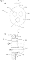
- FIG. 12 shows, in a schematic and simplified form, an end duct assembly 10 for a habitable vehicle heater.
- the following description refers both to the top view ( Figure 1A ), as well as to the sectional view ( Figure 1B ).
- the line arrangement 10 has a line end piece 12 which, in the example shown, is arranged in a wall 14, for example a wall of the habitable vehicle or a wall of a compartment in which the heating device is accommodated.
- the line end piece 12 has a first exhaust pipe section 16-1 for discharging exhaust gases. Furthermore, the line end piece 12 includes a second exhaust pipe section 16-2. Below the two exhaust pipe sections 16-1, 16-2, a combustion air pipe section 18 is arranged for supplying combustion air to an associated burner of the heater.
- the two exhaust pipe sections 16 - 1 , 16 - 2 and the combustion pipe section 18 are provided in a sleeve section 20 so that they are parallel and immovable relative to one another.
- the outer side 22 of the sleeve section 20 delimits the line arrangement towards the environment.
- the pipe end piece 12 is designed in such a way that it also has a screen 24 in which the mouths of the various pipe sections 16 - 1 , 16 - 2 , 18 are formed and which serves to cover an opening 26 provided in the wall 14 , in which the line end piece 12 is accommodated.
- Further exhaust pipe sections 16-3 or combustion pipe sections 18-1 can be connected to the line end piece 12.
- This line sections 16-3. 18-1 can be rigid or flexible.
- the tube sections 16-3 and 18-1 are preferably designed in such a way that the line end piece 12 can be connected to its tube sections 16-1, 16-2, 18 in a simple manner, in particular by forming a plug-in connection. It is also conceivable that flexible pipe sections 16-3, 18 are attached to the line end piece 12 by means of pipe clamps, which are not shown here.
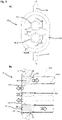
- FIG. 12 shows, again in a schematic and simplified form, an end duct assembly 10 for a habitable vehicle heater.
- the following description refers both to the top view ( Figure 2A ), as well as to the sectional view ( Figure 2B ).
- the line arrangement 10 has a line end piece 12 which, in the example shown, is arranged in a wall 14, for example a wall of the habitable vehicle or a wall of a compartment in which the heating device is accommodated.
- the line end piece 12 has a first exhaust pipe section 16-1 for discharging exhaust gases. Furthermore, the line end piece 12 includes a second exhaust pipe section 16-2.
- the two exhaust pipe sections 16-1, 16-2 are surrounded by a combustion air pipe section 18, which is used to supply combustion air to an associated burner of the heater.
- the two exhaust pipe sections 16-1, 16-2 and the combustion pipe section 18 are provided parallel and immovable relative to one another.
- the line end piece 12 is designed in such a way that it also comprises a screen 24 in which the mouths of the various tube sections 16-1, 16-2, 18 are formed and which serves to cover an opening 26 provided in the wall 14 in which the pipe end piece 12 is received.
- the two exhaust pipe sections 16 - 1 , 16 - 2 are connected to the surrounding combustion air pipe section 18 by means of strut-like elements 28 .
- each exhaust pipe section 16 - 1 , 16 - 2 is supported on the combustion air pipe section 18 by means of three struts 28 .
- Additional exhaust pipe sections 16-3, 16-4 or combustion pipe sections 18-1 can be connected to line end piece 12.
- These line sections 16-3, 16-4, 18-1 can be rigid or flexible.
- the tube sections 16-3, 16-4 and 18-1 are preferably designed in such a way that the line end piece 12 can be connected to its tube sections 16-1, 16-2, 18 in a simple manner, in particular by forming a plug-in connection. It is also conceivable that flexible pipe sections 16-3, 16-4, 18-1 are attached to the line end piece 12 by means of pipe clamps, not shown here.
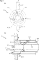
- FIG. 12 shows, again in a schematic and simplified form, an end duct assembly 10 for a habitable vehicle heater.
- the following description refers both to the top view ( Figure 3A ), as well as to the sectional view ( Figure 3B ).
- the line arrangement 10 has a line end piece 12 which, in the example shown, is arranged in a wall 14, for example a wall of the habitable vehicle or a wall of a compartment in which the heating device is accommodated.
- the line end piece 12 has a first exhaust pipe section 16-1 for discharging exhaust gases. Furthermore, the line end piece 12 includes a second exhaust pipe section 16-2.
- the two exhaust pipe sections 16-1, 16-2 are surrounded by a combustion air pipe section 18, which is used to supply combustion air to an associated burner of the heater.
- the two exhaust pipe sections 16-1, 16-2 and the combustion pipe section 18 are provided parallel and immovable relative to one another.
- the exhaust pipe sections 16-1, 16-2 and the combustion air pipe section 18 are arranged concentrically with one another.
- the first exhaust pipe section 16-1 has a circular cross section.
- the second exhaust pipe section 16-2 is arranged annularly in cross-section around the first exhaust pipe section 16-1.
- the combustion air pipe section 18 is arranged annularly in cross section around the second exhaust pipe section 16-2.
- the pipe end piece 12 is designed in such a way that it also has a screen 24 in which the mouths of the various pipe sections 16 - 1 , 16 - 2 , 18 are formed and which serves to cover an opening 26 provided in the wall 14 , in which the line end piece 12 is accommodated.
- the two exhaust pipe sections 16-1, 16-2 are connected to the surrounding combustion air pipe section 18 or to one another by means of strut-like elements 28.
- the first exhaust pipe section 16-1 is supported by three struts 28 on the second exhaust pipe section 16-2.
- the second exhaust pipe section 16 - 2 is in turn supported on the combustion air pipe section 18 by means of three struts 28 .
- Additional exhaust pipe sections 16-3, 16-4 or combustion pipe sections 18-1 can be connected to line end piece 12. These line sections 16-3, 16-4, 18-1 can be rigid or flexible.
- the tube sections 16-3, 16-4 and 18-1 are preferably designed in such a way that the line end piece 12 can be connected to its tube sections 16-1, 16-2, 18 in a simple manner, in particular by forming a plug-in connection. It is also conceivable that flexible pipe sections 16-3, 16-4, 18-1 are attached to the line end piece 12 by means of pipe clamps, not shown here.
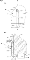
- FIG. 12 again shows in a schematic and simplified form an end line arrangement 10 for a heater 30 (indicated by dashed lines) of a habitable vehicle.
- the following description refers both to the top view ( Figure 4A ), as well as to the sectional view ( Figure 4B ).
- the duct assembly 10 includes an extension piece 32 which, in the example shown, is disposed along a wall 14 and an underside 34, such as a wall and underside of the habitable vehicle.
- the extension piece 32 has a first exhaust pipe section 16-1 for discharging exhaust gases.
- the exhaust pipe section 16-1 is surrounded by a combustion air pipe section 18, which is used to supply combustion air to an associated burner of the heater 30.
- the exhaust pipe section 16-1 and the combustion pipe section 18 are provided in parallel and immovable relative to each other.
- the exhaust pipe section 16-1 and the combustion air pipe section 18 is arranged concentrically to one another.
- the first exhaust pipe section 16-1 has a circular cross section.
- the combustion air pipe section 18 is arranged annularly in cross section around the first exhaust pipe section 16-1.
- the heater 30 indicated is accommodated in a compartment 36 under the floor.
- a side wall 38 of the compartment 36 is compared with the Figures 1 to 3 modified line end piece 112.
- the modified line end piece 112 usually forms the free end of the end-side line arrangement 10, so that exhaust gases are discharged under the floor, ie under the floor of the vehicle or the habitable vehicle body, and combustion air is also sucked in under the floor accordingly.
- the heating device 30 is designed in such a way that it itself is mounted under the floor and is therefore free of a compartment.
- the exhaust gas does not flow out under the floor, but rather at another point, in particular not under the floor, which is preferably also higher than the modified line end piece 112.
- the extension piece 32 can optionally be used for this purpose. It is provided that the extension piece can be connected to the modified line end piece 112 if necessary.
- the extension piece 32 has a first extension section 32-1 and a second extension section 32-2.
- the two extension sections 32-1, 32-2 are connected to one another by means of a bent line section 32-3.
- the first extension section 32-1 and the second extension section 32-2 are arranged substantially orthogonally to one another.
- a further curved line section 32-4 can be connected to the second extension section 32-2.
- the extension sections may be integrally formed with each other such that the extension piece 32 is an integral component.
- the extension sections can also be plugged together so that the extension piece 32 can be carried along in the habitable vehicle disassembled into individual extension sections.
- a fastening device 40 can be provided in an upper area of the extension piece 32, for example in the second extension section 32-2.
- the fastening device 40 serves in particular to secure the extension piece 32 to the wall 14 of the vehicle.
- the fastening device 40 can be designed, for example, as a suction cup which is attached to the extension piece 32 and whose suction side is brought into contact with the wall 14 or is.
- fastening devices are also conceivable, in particular fastening devices are also conceivable in which complementary fastening elements are provided on the extension piece 32 and the wall 14, by means of which a form-fitting and/or non-positive connection can be produced if required.
- a kind of eyelet or opening could be provided on the wall 14, into which a hook element attached to the extension piece 32 can be hung.
- a snap-in connection can also be considered as a fastening device, for example with a snap-in element protruding from the extension piece 32 and which can be releasably engaged with a snap-in opening provided on the wall 14 .
- FIG. 12 again shows in a schematic and simplified form an end line arrangement 10 for a heater 30 (indicated by dashed lines) of a habitable vehicle.
- the following description refers both to the top view ( Figure 5A ), as well as to the sectional view ( Figure 5B ).
- the duct assembly 10 includes an extension piece 32 which, in the example shown, is disposed along a wall 14 and an underside 34, such as a wall and underside of the habitable vehicle.
- the extension piece 32 has a first exhaust pipe section 16-1 and a second exhaust pipe section 16-2 for discharging exhaust gases.
- the exhaust pipe sections 16-1, 16-2 are surrounded by a combustion air pipe section 18, which is used to supply combustion air to an associated burner of the heater 30.
- the exhaust pipe sections 16-1, 16-2 and the combustion pipe section 18 are provided parallel and immovable relative to one another.
- the first exhaust pipe section 16 - 1 and the second exhaust pipe section 16 - 2 are arranged side by side and accommodated in the combustion air pipe section 18 .
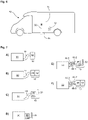
- FIG. 6 shows a habitable vehicle 42, here a mobile home, in a very greatly simplified and schematic representation.
- a side wall 14 of the habitable vehicle 42 the arrangement of a line end piece 12 of an end-side line arrangement is shown as an example.
- the line end piece 12 shown corresponds to the example of 2 . It can instead of the line end 12 of 2 other line end pieces 12 may be arranged on the vehicle 42, such as those line end pieces of 1 and 3 .
- extension piece 32 of the end line arrangement is shown as an example.
- the extension piece 32 is shown as an example figure 5 with two exhaust pipe sections.
- the extension piece 32 is connected or can be connected to an underfloor heating device which is provided on an underside 34 of the vehicle 42 or the vehicle body.
- the extension piece 32 according to 4 be provided on a vehicle 42.
- FIG. 7 shows in partial figures A) to F) purely schematically different designs or configurations of an end-side line arrangement 10 in relation to an associated heating device 30.
- FIG. 7A is the cable end piece 12 (see Figures 1 to 3 ) connected to heater 30 by flexible tubing 44 .
- the flexible tubes 44 are like this out that a corresponding connection to the exhaust pipe sections 16-1, 16-2 and the combustion air pipe section 18 in the line end piece 12 can be made possible.
- the line end 12 according to figures 2 and 3 be deployed.
- the terminal lead assembly includes only the lead end fitting 12 .
- a line adapter 46 is attached to the line end piece 12, which is then connected to the flexible tubes 44.
- the line adapter 46 is designed in particular in such a way that the line end piece 12 can be plugged onto the line adapter.
- the terminal lead assembly 10 includes the lead adapter 46 and the lead end fitting 12 .
- the plugging is an example of a quick attachment system.
- An alternative includes, for example, a bayonet system.
- FIG. 7C is an extension piece 32 ( 4 and 5 ) attached to flexible tubing 44 by means of a conduit adapter 46.
- the line adapter shown here can also be used as a line end piece 112 within the meaning of figure 5 be trained or understood.
- the end line assembly 10 includes the line adapter 46 or line end piece 112 and the extension piece 32 .
- FIG. 7D A configuration is also conceivable in which a line adapter 46 is attached directly to the heating device and the extension piece 32 is provided on the line adapter 46 .
- the line adapter 46 as a line end within the meaning of figure 5 be trained.
- the end line assembly 10 includes the line adapter 46 or line end piece 112 and the extension piece 32 .
Landscapes
- Engineering & Computer Science (AREA)
- Mechanical Engineering (AREA)
- Physics & Mathematics (AREA)
- Thermal Sciences (AREA)
- Chemical & Material Sciences (AREA)
- Combustion & Propulsion (AREA)
- General Engineering & Computer Science (AREA)
- Air-Conditioning For Vehicles (AREA)
- Quick-Acting Or Multi-Walled Pipe Joints (AREA)
Description
- Die Erfindung betrifft eine endseitige Leitungsanordnung für ein Heizgerät eines bewohnbaren Fahrzeugs, insbesondere Wohnwagen, Wohnmobil oder Schiff.
- Bei der Anordnung von Heizgeräten an bzw. in bewohnbaren Fahrzeugen ist es erforderlich, je nach Typ des verwendeten Heizgeräts, das einen oder mehrere Brenner aufweisen kann, und je nach dessen Unterbringung in einem Teil bzw. Kompartiment des Fahrzeugs, eine sichere Ableitung von Abgasen und eine ausreichende Zuleitung von Verbrennungsluft bereitzustellen. Dabei ist es insbesondere wünschenswert, dass in der Außenhaut des Fahrzeugs bzw. des bewohnbaren Aufbaus möglichst wenige bzw. möglichst kleine Öffnungen vorgesehen werden müssen. Für die Ableitung von Abgasen und für die Zuleitung von Verbrennungsluft sind in bekannten Systemen zwei voneinander getrennte Rohre bzw. Leitungen vorgesehen. Die Anzahl an getrennten Leitungen erhöht sich im Falle eines Heizgeräts, das zwei Brenner (alternative Bezeichung ist Feuerstätte) aufweist, von denen einer für das Erwärmen von Luft und der andere für das Erwärmen von Wasser eingesetzt wird.
- Aus der
FR 787 389 A US 4,621,609 A sowie derEP 1 227 276 A2 sind Heizgeräte mit endseitigen Leitungsanordnungen bekannt. - In der
GB 2 165 939 A - Aus der
EP 0 637 719 A2 ist ein Außenwandabschluss für einen Verbrennungsluft- und Abgaskanal eines mit einem Brennersystem arbeitenden Heizgeräts bekannt. - Die
GB 2 165 934 A - Der Erfindung liegt die Aufgabe zu Grunde, ein bewohnbares Fahrzeug mit einer endseitigen Leitungsanordnung anzugeben, bei der eine vorschriftsgemäße Ableitung von Abgasen unter Vermeidung von Abgasrückströmungen in eine der anderen Leitungen oder/und von Abgasansammlungen, insbesondere unterhalb des Fahrzeugbodens, ermöglicht ist.
- Die Aufgabe wird durch ein bewohnbares Fahrzeug mit den Merkmalen des Anspruchs 1 gelöst. Ausgestaltungen der Erfindung sind in den abhängigen Ansprüchen angegeben.
- Dazu wird eine endseitige Leitungsanordnung für ein Heizgerät eines bewohnbaren Fahrzeugs, insbesondere Wohnwagen, Wohnmobil oder Schiff, angegeben, mit
- wenigstens einem Abgasrohrabschnitt zum Ableiten von Abgasen eines zugeordneten Brenners des Heizgerätes;
- wenigstens einem Verbrennungsluftrohrabschnitt zum Zuleiten von Verbrennungsluft zu einem zugeordneten Brenner des Heizgeräts,
- wobei der Abgasrohrabschnitt und der Verbrennungsrohrabschnitt relativ zueinander parallel und unbeweglich in einem Hülsenabschnitt vorgesehen sind, dessen Außenseite die Leitungsanordnung zur Umgebung hin begrenzt.
- Die gemeinsame Unterbringung von Abgasrohrabschnitt und Verbrennungsluftrohrabschnitt in einem Hülsenabschnitt ermöglicht eine kompakte Bauweise der Leitungsanordnung. Da der Hülsenabschnitt die Leitungsanordnung zur Umgebung hin begrenzt, ist lediglich eine Öffnung in einer Fahrzeugwand erforderlich, um den Austritt sowohl der Abgasleitung als auch der Verbrennungsluftleitung zu ermöglichen.
- Der Hülsenabschnitt kann dabei durch den Verbrennungsluftrohrabschnitt gebildet sein. In diesem Fall bildet der Verbrennungsluftrohrabschnitt die äußere Begrenzung der Leitungsanordnung zur Umgebung hin. Dabei ist der wenigstens eine Abgasrohrabschnitt innerhalb des Verbrennungsluftrohrabschnitts angeordnet. Hierdurch wird eine kompakte Bauweise der Leitungsanordnung erreicht.
- Die endseitige Leitungsanordnung kann wenigstens zwei Abgasrohrabschnitte aufweisen, die strömungstechnisch voneinander getrennt sind. Eine derartige Leitungsanordnung kann für ein Heizgerät mit mindestens zwei Brennern (bzw. zwei Feuerstätten) eingesetzt werden, wobei jeder Abgasrohrabschnitt jeweils mit einem zugeordneten Brenner strömungstechnisch verbindbar bzw. verbunden ist. Dabei sind die beiden Abgasrohrabschnitte gemeinsam in dem Hülsenabschnitt oder in dem den Hülsenabschnitt bildenden Verbrennungsluftrohrabschnitt aufgenommen. Auch dies ermöglicht eine kompakte Bauweise der Leitungsanordnung, so dass auch zwei Abgasleitungen zusammen mit einer Verbrennungsluftleitung einfach im Bereich der Außenhaut des Fahrzeugs angeordnet bzw. aus dem Fahrzeug geführt werden können.
- Bei der endseitigen Leitungsanordnung kann der Verbrennungsluftrohrabschnitt den Abgasrohrabschnitt bzw. die Abgasrohrabschnitte umgeben, derart, dass der Abgasrohrabschnitt bzw. die Abgasrohrabschnitte von Verbrennungsluft umströmt ist.
- Weiter können bei der endseitigen Leitungsanordnung der Abgasrohrabschnitt bzw. die Abgasrohrabschnitte und der Verbrennungsrohrabschnitt konzentrisch zueinander angeordnet sein. Hierdurch kann eine kompakte und einfach anzuschließende Leitungsanordnung bereitgestellt werden. Im Falle einer Leitungsanordnung mit zwei Abgasrohrabschnitten kann beispielsweise ein erster Abgasrohrabschnitt im Querschnitt kreisförmig ausgebildet sein und das Zentrum der konzentrischen Leitungsanordnung bilden. Der zweite Abgasrohrabschnitt kann in einem solchen Falle ringförmig um den ersten Abgasrohrabschnitt angeordnet sein. Schließlich kann bei einer solchen Konstellation der Verbrennungsluftrohrabschnitt ringförmig um den zweiten Abgasrohrabschnitt ausgebildet sein. Dabei kann der Verbrennungsluftrohrabschnitt die Leitungsanordnung nach außen hin begrenzen.
- Die Leitungsanordnung umfasst ein Leitungsendstück, das auf seiner dem Heizgerät abgewandten Seite eine Mündung für den Abgasrohrabschnitt bzw. die Abgasrohrabschnitte und den Verbrennungsluftrohrabschnitt bildet. Dabei kann das Leitungsendstück in eine Wand des bewohnbaren Fahrzeugs einsetzbar sein, insbesondere darin befestigbar sein. Alternativ kann ein solches Leitungsendstück auch in einer Wand eines Kompartiments vorgesehen sein, das unterhalb des Bodens des Innenraums, also sogenannt unterflur, angeordnet ist und in dem ein Heizgerät unterflur angeordnet ist.
- Die Leitungsanordnung umfasst ein Verlängerungsstück, das wenigstens einen gebogenen Leitungsabschnitt aufweist, der zwischen einem ersten Verlängerungsabschnitt und einem zweiten Verlängerungsabschnitt angeordnet ist, wobei der erste Verlängerungsabschnitt bezogen auf die Strömungsrichtung von Abgas stromaufwärts des gebogenen Leitungsabschnitts angeordnet ist. Ein solches Verlängerungsstück ermöglicht das Ableiten von Abgasen zu einem Bereich, der sich weiter weg von dem Heizgerät befindet. Insbesondere ermöglicht ein solches Verlängerungsstück, dass Abgase, die von einem unterflur angeordneten Heizgerät stammen und unterhalb des Fahrzeugbodens ausgestoßen werden, an einer Stelle abzugeben, die nicht unterflur liegt, vorzugsweise höher liegt als der Fahrzeugboden.
- Das Verlängerungsstück kann eine Befestigungseinrichtung aufweisen, derart dass das Verlängerungsstück, insbesondere der zweite Verlängerungsabschnitt, an einer Wand des bewohnbaren Fahrzeugs fixierbar ist. Somit kann das Verlängerungsstück mittels seines Anschlusses im Bereich des Heizgeräts und mittels der Befestigungseinrichtung sicher am Fahrzeug befestigt bzw. gesichert werden.
- Das Verlängerungsstück kann einen ersten gebogenen Leitungsabschnitt aufweisen, der zwischen dem ersten Verlängerungsabschnitt und dem zweiten Verlängerungsabschnitt angeordnet ist, und einen zweiten gebogenen Leitungsabschnitt aufweist, der bezogen auf die Strömungsrichtung von Abgas stromabwärts an dem zweiten Verlängerungsabschnitt angeordnet ist. Ferner können der erste Verlängerungsabschnitt und der zweite Verlängerungsabschnitt im Wesentlichen orthogonal zueinander ausgerichtet sein. Hierdurch ist es möglich, dass mittels des Verlängerungsstücks die Abgasleitung von unterflur zu einem Rand des Fahrzeugboden geführt und dann entlang einer Wand des Fahrzeugs nach oben geführt wird.
- Die Leitungsanordnung umfasst einen mit dem Heizgerät unmittelbar oder mittelbar verbundenen Leitungsadapter, an dem das Leitungsendstück oder das Verlängerungsstück abnehmbar angebracht ist, insbesondere in der Art einer Steckverbindung. Dabei weist der Leitungsadapter in Bezug auf die Anordnung von Abgasrohrabschnitt(en) und Verbrennungsluftrohrabschnitt eine gleiche Konfiguration auf, wie das anzuschließende Leitungsendstück bzw. Verlängerungsstück. Ein solcher Leitungsadapter kann beispielsweise dazu dienen, einzelne vom Heizgerät abgehende Abgasleitungen bzw. Verbrennungsluftleitungen zusammenzuführen, so dass die einzelnen Leitungen dann mit der endseitigen Leitungsanordnung fluidtechnisch verbunden werden kann
- Das Leitungsendstück kann bezogen auf die Strömungsrichtung von Abgas stromabwärts des zweiten Verlängerungsabschnitts an dem Verlängerungsstück anbringbar sein. Anders ausgedrückt kann ein beispielsweise in einer Wandung verwendetes Endstück beispielsweise abgenommen werden und stattdessen das Verlängerungsstück angebracht werden, wobei dann das Endstück auf das freie Ende des Verlängerungsstücks aufsetzbar ist.
- Die Erfindung betrifft ferner auch ein Heizungssystem für ein bewohnbares Fahrzeug, insbesondere Wohnwagen, Wohnmobil oder Schiff, mit einem Heizgerät zum Erwärmen von Luft im Innenraum des Fahrzeugs oder/und zum Erwärmen von Wasser, wobei das Heizgerät zum Ableiten von Abgasen eines Brenners oder mehrerer Brenner und zum Zuleiten von Verbrennungsluft zu dem Brenner oder zu den Brennern eine oben beschriebene endseitige Leitungsanordnung aufweist.
- Bei dem Heizungssystem kann strömungstechnisch zwischen dem Heizgerät und der endseitigen Leitungsanordnung wenigstens ein flexibler Abgasrohrabschnitt und wenigstens ein flexibler Verbrennungsluftrohrabschnitt angeordnet sein. Dabei kann der flexible Abgasrohrabschnitt oder können mehrere flexible Abgasrohrabschnitte in dem flexiblen Verbrennungsrohrabschnitt aufgenommen sein. Alternativ können der wenigstens eine flexible Abgasrohrabschnitt und der flexible Verbrennungsluftrohrabschnitt als separate bzw. nebeneinander angeordnete Leitungen ausgebildet sein. Wie bereits oben beschrieben worden ist, können solche flexiblen Leitungsabschnitte beispielsweise an einem Leitungsadapter der Leitungsanordnung angeschlossen werden bzw. sein.
- Schließlich betrifft die Erfindung auch ein bewohnbares Fahrzeug, insbesondere Wohnwagen, Wohnmobil oder Schiff, mit einem oben beschriebenen Heizungssystem bzw. einer oben beschriebenen Leitungsanordnung.
- Bei dem bewohnbaren Fahrzeug kann das Heizgerät in einem vom Innenraum durch eine Abdeckeinrichtung getrennten Kompartiment aufgenommen sein, wobei das Kompartiment als Unterflurkompartiment unterhalb des Bodens des Innenraums ausgebildet ist oder als Überflurkompartiment durch den Innenraum begrenzende Seitenwände ausgebildet ist.
- Ferner kann bei dem bewohnbaren Fahrzeug die endseitige Leitungsanordnung, insbesondere deren Verlängerungsstück, bei in dem Unterflurkompartiment angeordnetem Heizgerät vollständig außerhalb des Innenraums des Fahrzeugs angeordnet sein. Alternativ kann bei dem bewohnbaren Fahrzeug die endseitige Leitungsanordnung, insbesondere deren Verlängerungsstück, bei unterhalb des Bodens des Innenraums angeordnetem Heizgerät vollständig außerhalb des Innenraums des Fahrzeugs angeordnet sein. Dabei kann das Verlängerungsstück zusätzlich zum strömungstechnischen Anschluss im Bereich des Unterflurkompartiments mittels einer Befestigungseinrichtung an einer Außenseite einer Seitenwand des Fahrzeugs lösbar fixiert sein.
- Nachfolgend wird die Erfindung unter Bezugnahme auf die anliegenden Figuren beispielhaft und nicht einschränkend anhand verschiedener Ausführungsformen genauer beschrieben. Dabei zeigen
- Fig. 1
- eine schematische und vereinfachte Draufsicht (
Fig. 1A ) und zugehörige Schnittdarstellung (Fig. 1B ) entsprechend der Schnittlinie B-B eines ersten Beispiels eines Leitungsendstücks einer endseitigen Leitungsanordnung; - Fig. 2
- eine schematische und vereinfachte Draufsicht (
Fig. 2A ) und zugehörige Schnittdarstellung (Fig. 2B ) entsprechend der Schnittlinie B-B eines zweiten Beispiels eines Leitungsendstücks einer endseitigen Leitungsanordnung; - Fig. 3
- eine schematische und vereinfachte Draufsicht (
Fig. 3A ) und zugehörige Schnittdarstellung (Fig. 3B ) entsprechend der Schnittlinie B-B eines dritten Beispiels eines Leitungsendstücks einer endseitigen Leitungsanordnung; - Fig. 4
- eine schematische und vereinfachte Draufsicht (
Fig. 4A ) und zugehörige Schnittdarstellung (Fig. 4B ) entsprechend der Schnittlinie B-B eines ersten Beispiels eines Verlängerungsstücks einer endseitigen Leitungsanordnung; - Fig. 5
- eine schematische und vereinfachte Draufsicht (
Fig. 5A ) und zugehörige Schnittdarstellung (Fig. 5B ) entsprechend der Schnittlinie B-B eines zweiten Beispiels eines Verlängerungsstücks einer endseitigen Leitungsanordnung; - Fig. 6
- eine schematische und vereinfachte Ansicht ein bewohnbares Fahrzeug, an dem beispielhaft ein Leitungsendstück bzw. ein Verlängerungsstück einer endseitigen Leitungsanordnung angeordnet sind;
- Fig. 7
- in den Teilfiguren A) bis F) schematische Darstellungen möglicher Konfigurationen einer endseitigen Leitungsanordnung.
- In allen nachfolgenden Figuren wird eine Strömungsrichtung SA von Abgas durch einen entsprechend bezeichneten Pfeil gekennzeichnet. Die Strömungsrichtung SV von Verbrennungsluft, die aus der Umgebung angesaugt wird, ist der Abgasströmungsrichtung SA entgegengesetzt.
-
Fig. 1 zeigt in einer schematischen und vereinfachten Form eine endseitige Leitungsanordnung 10 für ein Heizgerät eines bewohnbaren Fahrzeugs. Die nachfolgende Beschreibung bezieht sich sowohl auf die Draufsicht (Fig. 1A ), als auch auf die Schnittdarstellung (Fig. 1B ). Die Leitungsanordnung 10 weist ein Leitungsendstück 12 auf, das im gezeigten Beispiel in einer Wand 14 angeordnet ist, beispielsweise einer Wand des bewohnbaren Fahrzeugs oder einer Wand eines Kompartiments, in dem das Heizgerät untergebracht ist. - Das Leitungsendstück 12 weist einen ersten Abgasrohrabschnitt 16-1 zum Ableiten von Abgasen auf. Weiter umfasst das Leitungsendstück 12 einen zweiten Abgasrohrabschnitt 16-2. Unterhalb der beiden Abgasrohrabschnitte 16-1, 16-2 ist ein Verbrennungsluftrohrabschnitt 18 angeordnet, der zum Zuleiten von Verbrennungsluft zu einem zugeordneten Brenner des Heizgeräts dient. Die beiden Abgasrohrabschnitt 16-1, 16-2 und der Verbrennungsrohrabschnitt 18 sind dabei relativ zueinander parallel und unbeweglich in einem Hülsenabschnitt 20 vorgesehen. Die Außenseite 22 des Hülsenabschnitts 20 begrenzt die Leitungsanordnung zur Umgebung hin. Das Leitungsendstück 12 ist in diesem Beispiel so ausgebildet, dass es auch eine Blende 24 aufweist, in der die Mündungen der verschiedenen Rohrabschnitte 16-1, 16-2, 18 ausgebildet sind und die dazu dient, eine in der Wand 14 vorgesehene Öffnung 26 abzudecken, in der das Leitungsendstück 12 aufgenommen ist.
- Mit dem Leitungsendstück 12 können weitere Abgasrohrabschnitte 16-3 bzw. Verbrennungsrohrabschnitte 18-1 verbunden sein. Diese Leitungsabschnitte 16-3. 18-1 können starr oder flexibel ausgebildet sein. Bevorzugt sind die Rohrabschnitte 16-3 und 18-1 so ausgebildet, dass das Leitungsendstück 12 mit seinen Rohrabschnitten 16-1, 16-2, 18 in einfacher Weise verbunden werden kann, insbesondere durch Ausbildung einer Steckverbindung. Denkbar ist auch, dass flexible Rohrabschnitte 16-3, 18 mittels hier nicht dargestellter Rohrschellen an dem Leitungsendstück 12 angebracht werden.
-
Fig. 2 zeigt in einer schematischen und vereinfachten Form wiederum eine endseitige Leitungsanordnung 10 für ein Heizgerät eines bewohnbaren Fahrzeugs. Die nachfolgende Beschreibung bezieht sich sowohl auf die Draufsicht (Fig. 2A ), als auch auf die Schnittdarstellung (Fig. 2B ). Die Leitungsanordnung 10 weist ein Leitungsendstück 12 auf, das im gezeigten Beispiel in einer Wand 14 angeordnet ist, beispielsweise einer Wand des bewohnbaren Fahrzeugs oder einer Wand eines Kompartiments, in dem das Heizgerät untergebracht ist. - Das Leitungsendstück 12 weist einen ersten Abgasrohrabschnitt 16-1 zum Ableiten von Abgasen auf. Weiter umfasst das Leitungsendstück 12 einen zweiten Abgasrohrabschnitt 16-2. Die beiden Abgasrohrabschnitte 16-1, 16-2 sind umgeben von einem Verbrennungsluftrohrabschnitt 18, der zum Zuleiten von Verbrennungsluft zu einem zugeordneten Brenner des Heizgeräts dient. Die beiden Abgasrohrabschnitt 16-1, 16-2 und der Verbrennungsrohrabschnitt 18 sind dabei relativ zueinander parallel und unbeweglich vorgesehen.
- Im Unterschied zum Beispiel der
Fig. 1 bildet der Verbrennungsluftrohrabschnitt 18 den in derFig. 1 separat gezeigten Hülsenabschnitt 20. Die Außenseite 22 des Verbrennungsluftrohrabschnitts 18 begrenzt die Leitungsanordnung 10 zur Umgebung hin. Das Leitungsendstück 12 ist in diesem Beispiel so ausgebildet, dass es auch eine Blende 24 aufweist, in der die Mündungen der verschiedenen Rohrabschnitte 16-1, 16-2, 18 ausgebildet sind und die dazu dient, eine in der Wand 14 vorgesehene Öffnung 26 abzudecken, in der das Leitungsendstück 12 aufgenommen ist. - Die beiden Abgasrohrabschnitte 16-1, 16-2 sind mittels strebenartiger Elemente 28 mit dem umgebenden Verbrennungsluftrohrabschnitt 18 verbunden. Im gezeigten Beispiel ist jeder Abgasrohrabschnitt 16-1,16-2 mittels dreier Streben 28 an dem Verbrennungsluftrohrabschnitt 18 abgestützt. Mit dem Leitungsendstück 12 können weitere Abgasrohrabschnitte 16-3, 16-4 bzw. Verbrennungsrohrabschnitte 18-1 verbunden sein. Diese Leitungsabschnitte 16-3, 16-4, 18-1 können starr oder flexibel ausgebildet sein. Bevorzugt sind die Rohrabschnitte 16-3, 16-4, und 18-1 so ausgebildet, dass das Leitungsendstück 12 mit seinen Rohrabschnitten 16-1, 16-2, 18 in einfacher Weise verbunden werden kann, insbesondere durch Ausbildung einer Steckverbindung. Denkbar ist auch, dass flexible Rohrabschnitte 16-3, 16-4, 18-1 mittels hier nicht dargestellter Rohrschellen an dem Leitungsendstück 12 angebracht werden.
-
Fig. 3 zeigt in einer schematischen und vereinfachten Form wiederum eine endseitige Leitungsanordnung 10 für ein Heizgerät eines bewohnbaren Fahrzeugs. Die nachfolgende Beschreibung bezieht sich sowohl auf die Draufsicht (Fig. 3A ), als auch auf die Schnittdarstellung (Fig. 3B ). Die Leitungsanordnung 10 weist ein Leitungsendstück 12 auf, das im gezeigten Beispiel in einer Wand 14 angeordnet ist, beispielsweise einer Wand des bewohnbaren Fahrzeugs oder einer Wand eines Kompartiments, in dem das Heizgerät untergebracht ist. - Das Leitungsendstück 12 weist einen ersten Abgasrohrabschnitt 16-1 zum Ableiten von Abgasen auf. Weiter umfasst das Leitungsendstück 12 einen zweiten Abgasrohrabschnitt 16-2. Die beiden Abgasrohrabschnitte 16-1, 16-2 sind umgeben von einem Verbrennungsluftrohrabschnitt 18, der zum Zuleiten von Verbrennungsluft zu einem zugeordneten Brenner des Heizgeräts dient. Die beiden Abgasrohrabschnitt 16-1, 16-2 und der Verbrennungsrohrabschnitt 18 sind dabei relativ zueinander parallel und unbeweglich vorgesehen. In diesem Beispiel sind die Abgasrohrabschnitte 16-1, 16-2 und der Verbrennungsluftrohrabschnitt 18 konzentrisch zueinander angeordnet. Dabei der erste Abgasrohrabschnitt 16-1 einen kreisförmigen Querschnitt auf. Der zweite Abgasrohrabschnitt 16-2 ist im Querschnitt ringförmig um den ersten Abgasrohrabschnitt 16-1 angeordnet. Der Verbrennungsluftrohrabschnitt 18 ist im Querschnitt ringförmig um den zweiten Abgasrohrabschnitt 16-2 angeordnet.
- Wie im Beispiel der
Fig. 2 (und im Unterschied zum Beispiel derFig. 1 ) bildet der Verbrennungsluftrohrabschnitt 18 den in derFig. 1 separat gezeigten Hülsenabschnitt 20. Die Außenseite 22 des Verbrennungsluftrohrabschnitts 18 begrenzt die Leitungsanordnung 10 zur Umgebung hin. Das Leitungsendstück 12 ist in diesem Beispiel so ausgebildet, dass es auch eine Blende 24 aufweist, in der die Mündungen der verschiedenen Rohrabschnitte 16-1, 16-2, 18 ausgebildet sind und die dazu dient, eine in der Wand 14 vorgesehene Öffnung 26 abzudecken, in der das Leitungsendstück 12 aufgenommen ist. - Die beiden Abgasrohrabschnitte 16-1, 16-2 sind mittels strebenartiger Elemente 28 mit dem umgebenden Verbrennungsluftrohrabschnitt 18 bzw. untereinander verbunden. Im gezeigten Beispiel ist der erste Abgasrohrabschnitt 16-1 mittels dreier Streben 28 an dem zweiten Abgasrohrabschnitt 16-2 abgestützt. Der zweite Abgasrohrabschnitt 16-2 ist wiederum mittels dreier Streben 28 an dem Verbrennungsluftrohrabschnitt 18 abgestützt. Mit dem Leitungsendstück 12 können weitere Abgasrohrabschnitte 16-3, 16-4 bzw. Verbrennungsrohrabschnitte 18-1 verbunden sein. Diese Leitungsabschnitte 16-3, 16-4, 18-1 können starr oder flexibel ausgebildet sein. Bevorzugt sind die Rohrabschnitte 16-3, 16-4, und 18-1 so ausgebildet, dass das Leitungsendstück 12 mit seinen Rohrabschnitten 16-1, 16-2, 18 in einfacher Weise verbunden werden kann, insbesondere durch Ausbildung einer Steckverbindung. Denkbar ist auch, dass flexible Rohrabschnitte 16-3, 16-4, 18-1 mittels hier nicht dargestellter Rohrschellen an dem Leitungsendstück 12 angebracht werden.
-
Fig. 4 zeigt in einer schematischen und vereinfachten Form wiederum eine endseitige Leitungsanordnung 10 für ein Heizgerät 30 (gestrichelt angedeutet) eines bewohnbaren Fahrzeugs. Die nachfolgende Beschreibung bezieht sich sowohl auf die Draufsicht (Fig. 4A ), als auch auf die Schnittdarstellung (Fig. 4B ). Die Leitungsanordnung 10 weist ein Verlängerungsstück 32 auf, das im gezeigten Beispiel entlang einer Wand 14 und einer Unterseite 34 angeordnet ist, beispielsweise einer Wand und einer Unterseite des bewohnbaren Fahrzeugs. - Das Verlängerungsstück 32 weist einen ersten Abgasrohrabschnitt 16-1 zum Ableiten von Abgasen auf. Der Abgasrohrabschnitt 16-1 ist umgeben von einem Verbrennungsluftrohrabschnitt 18, der zum Zuleiten von Verbrennungsluft zu einem zugeordneten Brenner des Heizgeräts 30 dient. Der Abgasrohrabschnitt 16-1 und der Verbrennungsrohrabschnitt 18 sind dabei relativ zueinander parallel und unbeweglich vorgesehen. In diesem Beispiel sind der Abgasrohrabschnitt 16-1 und der Verbrennungsluftrohrabschnitt 18 konzentrisch zueinander angeordnet. Dabei der erste Abgasrohrabschnitt 16-1 einen kreisförmigen Querschnitt auf. Der Verbrennungsluftrohrabschnitt 18 ist im Querschnitt ringförmig um den ersten Abgasrohrabschnitt 16-1 angeordnet.
- In diesem Beispiel ist das angedeutete Heizgerät 30 unterflur in einem Kompartiment 36 aufgenommen. In einer Seitenwand 38 des Kompartiments 36 ist eine verglichen mit den
Figuren 1 bis 3 modifiziertes Leitungsendstück 112. Das modifizierte Leitungsendstück 112 bildet üblicherweise das freie Ende der endseitigen Leitungsanordnung 10, so dass Abgase unterflur, also unter dem Boden des Fahrzeugs bzw. des bewohnbaren Fahrzeugaufbaus ausgestoßen werden und entsprechend auch Verbrennungsluft unterflur angesaugt wird. In einer alternativen - nicht dargestellten - Ausführung ist das Heizgerät 30 so ausgeführt, dass es selbst und daher frei von einem Kompartiment unterflur angebracht ist. - Unter bestimmten Umständen kann es wünschenswert sein, dass das das Abgas nicht unterflur ausströmt, sondern an einer anderen, insbesondere nicht unterflur liegenden Stelle, die vorzugsweise auch höher liegt als das modifizierte Leitungsendstück 112. Hierzu kann das Verlängerungsstück 32 optional eingesetzt werden. Dabei ist vorgesehen, dass das Verlängerungsstück bei Bedarf mit dem modifizierten Leitungsendstück 112 verbunden werden kann.
- Das Verlängerungsstück 32 weist im vorliegenden Beispiel einen ersten Verlängerungsabschnitt 32-1 und einen zweiten Verlängerungsabschnitt 32-2 auf. Die beiden Verlängerungsabschnitte 32-1, 32-2 sind mittels eines gebogenen Leitungsabschnitts 32-3 miteinander verbunden. Wie unschwer aus der Darstellung der
Fig. 4B ersichtlich, sind der erste Verlängerungsabschnitt 32-1 und der zweite Verlängerungsabschnitt 32-2 im Wesentlichen orthogonal zueinander angeordnet. An den zweiten Verlängerungsabschnitt 32-2 kann sich ein weiterer gebogener Leitungsabschnitt 32-4 anschließen. Die Verlängerungsabschnitte können einstückig miteinander ausgebildet sein, so dass das Verlängerungsstück 32 ein integrales Bauteil ist. Alternativ können die Verlängerungsabschnitte auch zusammensteckbar sein, so dass das Verlängerungsstück 32 in einzelne Verlängerungsabschnitte zerlegt im bewohnbaren Fahrzeug mitgeführt werden kann. - In einem oberen Bereich des Verlängerungsstücks 32, beispielsweise im des zweiten Verlängerungsabschnitts 32-2 kann eine Befestigungseinrichtung 40 vorgesehen. Die Befestigungseinrichtung 40 dient insbesondere dazu, das Verlängerungsstück 32 an der Wand 14 des Fahrzeugs zu sichern. Die Befestigungseinrichtung 40 kann beispielsweise als Saugnapf ausgebildet sein, der an dem Verlängerungsstück 32 angebracht ist und dessen Saugseite mit der Wand 14 in Kontakt gebracht wird bzw. steht.
- Es sind auch andere Arten von Befestigungseinrichtungen denkbar, insbesondere wird auch an Befestigungseinrichtungen gedacht, bei denen an dem Verlängerungsstück 32 und der Wand 14 komplementäre Befestigungselemente vorgesehen, durch die bei Bedarf eine formschlüssige oder/und kraftschlüssige Verbindung herstellbar ist. Beispielsweise könnte an der Wand 14 eine Art Öse oder Öffnung vorgesehen sein, in die ein am Verlängerungsstück 32 angebrachtes Hakenelement einhängbar ist. Weiter kann als Befestigungseinrichtung auch eine Rastverbindung in Frage kommen, beispielsweise mit einem von dem Verlängerungsstück 32 vorstehenden Rastelement, das mit einer an der Wand 14 vorgesehenen Rastöffnung lösbar in Eingriff gebracht werden kann.
-
Fig. 5 zeigt in einer schematischen und vereinfachten Form wiederum eine endseitige Leitungsanordnung 10 für ein Heizgerät 30 (gestrichelt angedeutet) eines bewohnbaren Fahrzeugs. Die nachfolgende Beschreibung bezieht sich sowohl auf die Draufsicht (Fig. 5A ), als auch auf die Schnittdarstellung (Fig. 5B ). Die Leitungsanordnung 10 weist ein Verlängerungsstück 32 auf, das im gezeigten Beispiel entlang einer Wand 14 und einer Unterseite 34 angeordnet ist, beispielsweise einer Wand und einer Unterseite des bewohnbaren Fahrzeugs. - Das Verlängerungsstück 32 weist einen ersten Abgasrohrabschnitt 16-1 und einen zweiten Abgasrohrabschnitt 16-2 zum Ableiten von Abgasen auf. Die Abgasrohrabschnitte 16-1, 16-2 sind umgeben von einem Verbrennungsluftrohrabschnitt 18, der zum Zuleiten von Verbrennungsluft zu einem zugeordneten Brenner des Heizgeräts 30 dient. Die Abgasrohrabschnitte 16-1, 16-2 und der Verbrennungsrohrabschnitt 18 sind dabei relativ zueinander parallel und unbeweglich vorgesehen. In diesem Beispiel sind der erste Abgasrohrabschnitt 16-1 und der zweite Abgasrohrabschnitt 16-2 nebeneinander angeordnet und in dem Verbrennungsluftrohrabschnitt 18 aufgenommen.
- In Bezug auf weitere Merkmale des Verlängerungsstücks 32 und dessen Anordnung wird auf die Beschreibung zur
Figur 4 hingewiesen, die auch für das Beispiel derFig. 5 anwendbar ist. Entsprechend sind in derFig. 5 weitere Bezugszeichen aufgeführt, deren Beschreibung aber in Bezug auf dieFig. 4 vorgenommen worden ist. - Unter Bezugnahme auf die
Figuren 1 bis 5 wird darauf hingewiesen, dass die verschiedenen Anordnungen von Abgasrohrabschnitten 16-1, 16-2 und Verbrennungsluftrohrabschnitten 18, wie etwa nebeneinander, übereinander, ineinander, konzentrisch, sowohl für die Leitungsendstücke 12, als auch für das Verlängerungsstück 32 umgesetzt werden können. Es kann also jede für ein Leitungsendstück 12 gezeigte Anordnung für ein Verlängerungsstück 32 umgesetzt werden oder umgekehrt. Dies gilt selbstredend auch für das in derFig. 5 gezeigte Leitungsendstück 112. -
Fig. 6 zeigt in einer sehr stark vereinfachten und schematischen Darstellung ein bewohnbares Fahrzeug 42, hier ein Wohnmobil. In einer Seitenwand 14 des bewohnbaren Fahrzeugs 42 ist beispielhaft die Anordnung eines Leitungsendstücks 12 einer endseitigen Leitungsanordnung gezeigt. Das dargestellte Leitungsendstück 12 entspricht dem Beispiel derFig. 2 . Es können statt des Leitungsendstücks 12 derFig. 2 auch andere Leitungsendstücke 12 an dem Fahrzeug 42 angeordnet sein, etwa diejenigen Leitungsendstücke derFig. 1 und3 . - Ferner ist in
Fig. 6 beispielshaft die Anordnung eines Verlängerungsstücks 32 der endseitigen Leitungsanordnung gezeigt. Dargestellt ist beispielhaft das Verlängerungsstück 32 derFig. 5 mit zwei Abgasrohrabschnitten. Wie bereits unter Bezugnahme auf dieFig. 4 und5 erläutern worden ist, ist das Verlngerungsstück 32 mit einem unterflur angeordneten Heizgerät verbunden bzw. verbindbar, das an einer Unterseite 34 des Fahrzeugs 42 bzw. des Fahrzeugaufbaus vorgesehen ist. Selbstverständlich kann auch das Verlängerungsstück 32 gemäßFig. 4 an einem Fahrzeug 42 vorgesehen sein. - Auch wenn das Leitungsendstück 12 und das Verlängerungsstück 32 in der
Fig. 6 gemeinsam an dem Fahrzeug 42 dargestellt ist, wird darauf hingewiesen, dass üblicherweise nicht beide an dem gleichen Fahrzeug vorgesehen sind. Ferner wird darauf hingewiesen, dass das Leitungsendstück 12 und das Verlängerungsstück in Relation zu dem Fahrzeug 42 nicht maßstabsgetreu dargestellt sind. Vielmehr sind sie zum Zwecke der besseren Verständlichkeit vergrößert gezeichnet. -
Fig. 7 zeigt in den Teilfiguren A) bis F) rein schematisch verschiedene Ausgestaltungen bzw. Konfigurationen einer endseitigen Leitungsanordnung 10 in Bezug auf ein zugeordnetes Heizgerät 30. - Gemäß
Fig. 7A ist das Leitungsendstück 12 (sieheFig. 1 bis 3 ) mittels flexibler Rohre 44 mit dem Heizgerät 30 verbunden. Die flexiblen Rohre 44 sind dabei so geführt, dass ein entsprechender Anschluss an die Abgasrohrabschnitte 16-1, 16-2 und den Verbrennungsluftrohrabschnitt 18 in dem Leitungsendstück 12 ermöglicht werden kann. Im Beispiel derFig. 7A ) kann beispielsweise das Leitungsendstück 12 gemäßFiguren 2 und3 eingesetzt sein. Bei einer derartigen Konfiguration weist die endseitige Leitungsanordnung nur das Leitungsendstück 12 auf. - Gemäß
Fig. 7B ist an dem Leitungsendstück 12 ein Leitungsadapter 46 angebracht, der dann mit den flexiblen Rohren 44 verbunden ist. Der Leitungsadapter 46 ist dabei insbesondere so ausgeführt, dass das Leitungsendstück 12 auf den Leitungsadapter aufgesteckt werden kann. Bei einer derartigen Konfiguration weist die endseitige Leitungsanordnung 10 den Leitungsadapter 46 und das Leitungsendstück 12 auf. Das Aufstecken ist dabei ein Beispiel für ein Schnellbefestigungssystem. Eine Alternative umfasst beispielsweise ein Bajonettsystem. - Gemäß
Fig. 7C ist ein Verlängerungsstück 32 (Fig. 4 und5 ) mittels eines Leitungsadapters 46 an flexiblen Rohren 44 angebracht. Der hier dargestellte Leitungsadapter kann auch als Leitungsendstück 112 im Sinne derFig. 5 ausgebildet sein bzw. verstanden werden. Bei einer derartigen Konfiguration weist die endseitige Leitungsanordnung 10 den Leitungsadapter 46 bzw. das Leitungsendstück 112 und das Verlängerungsstück 32 auf. - Gemäß
Fig. 7D ist auch eine Konfiguration denkbar, bei der ein Leitungsadapter 46 unmittelbar an dem Heizgerät angebracht ist und das Verlängerungsstück 32 an dem Leitungsadapter 46 vorgesehen ist. Wie beim Beispiel derFig. 7C kann der Leitungsadapter 46 auch als Leitungsendstück im Sinne derFig. 5 ausgebildet sein. Bei einer derartigen Konfiguration weist die endseitige Leitungsanordnung 10 den Leitungsadapter 46 bzw. das Leitungsendstück 112 und das Verlängerungsstück 32 auf. - Gemäß
Fig. 7E und 7F können mit einem Heizgerät 30 verbundene einzelne Leitungen 44-1, 44-2, 44-3 mit einem Leitungsadapter 46 verbunden sein. Der Leitungsadapter kann dann mit einem Leitungsendstück 12 (Fig. 7F ) oder einem Verlängerungsstück 32 (Fig. 7E ) verbunden werden. Dabei ist der Leitungsadapter 46 so ausgestaltet, dass die heizgerätseitigen einzelnen Leitungen 44-1, 44-2, 44-3 strömungstechnisch so zusammengeführt werden, dass endseitig an dem Leitungsadapter 46 das Leitungsendstück 12 bzw. das Verlängerungsstück 32 mit den in denFig. 1 bis 5 dargestellten Anordnungen von Abgasrohrabschnitten 16-1, 16-2 und Verbrennungsluftabschnitten 18 angeschlossen werden können. Bei einer Konfiguration gemäßFig. 7E weist die endseitige Leitungsanordnung 10 den Adapter 46 bzw. das Leitungsendstück 112 und das Verlängerungsstück 32 auf. Bei einer Konfiguration gemäßFig. 7F weist die endseitige Leitungsanordnung 10 den Adapter 46 und das Leitungsendstück 12 auf.
Claims (7)
- Bewohnbares Fahrzeug (42), insbesondere Wohnwagen, Wohnmobil oder Schiff, mit einem Heizungssystem mit einem Heizgerät (30) zum Erwärmen von Luft im Innenraum des Fahrzeugs oder/und zum Erwärmen von Wasser,wobei das Heizgerät (30) zum Ableiten von Abgasen eines Brenners oder mehrerer Brenner und zum Zuleiten von Verbrennungsluft zu dem Brenner oder zu den Brennern eine endseitige Leitungsanordnung (10) aufweist; undwobei die endseitige Leitungsanordnung (10) wenigstens einen Abgasrohrabschnitt (16-1, 16-2) zum Ableiten von Abgasen eines zugeordneten Brenners des Heizgerätes (30) und wenigstens einen Verbrennungsluftrohrabschnitt (18) zum Zuleiten von Verbrennungsluft zu einem zugeordneten Brenner des Heizgeräts (30) aufweist;dadurch gekennzeichnet, dassder Abgasrohrabschnitt (16-1, 16-2) und der Verbrennungsrohrabschnitt (18) relativ zueinander parallel und unbeweglich in einem Hülsenabschnitt (20) vorgesehen sind, dessen Außenseite (22) die Leitungsanordnung (10) zur Umgebung hin begrenzt;das Heizgerät (30) in einem vom Innenraum durch eine Abdeckeinrichtung getrennten Kompartiment (36) aufgenommen ist, wobei das Kompartiment (36) als Unterflurkompartiment unterhalb des Bodens (34) des Innenraums ausgebildet ist;die Leitungsanordnung (10) vollständig außerhalb des Innenraums des Fahrzeugs (42) angeordnet ist;die Leitungsanordnung (10) ein Leitungsendstück (12) umfasst, das auf seiner dem Heizgerät (30) abgewandten Seite eine Mündung für den Abgasrohrabschnitt (16-1, 16-2) und den Verbrennungsluftrohrabschnitt (18) bildet;die Leitungsanordnung (10) ein Verlängerungsstück (32) umfasst, das wenigstens einen gebogenen Leitungsabschnitt (32-3) aufweist, der zwischen einem ersten Verlängerungsabschnitt (32-1) und einem zweiten Verlängerungsabschnitt (32-2) angeordnet ist, wobei der erste Verlängerungsabschnitt (32-1) bezogen auf die Strömungsrichtung (SA) von Abgas stromaufwärts des gebogenen Leitungsabschnitts (32-3) angeordnet ist; und dassdie Leitungsanordnung (10) einen mit dem Heizgerät (30) unmittelbar oder mittelbar verbundenen Leitungsadapter (46, 112) umfasst, an dem das Leitungsendstück (12) oder das Verlängerungsstück (32) abnehmbar angebracht ist, insbesondere in der Art einer Steckverbindung.
- Bewohnbares Fahrzeug nach Anspruch 1, wobei die Leitungsanordnung (10) wenigstens zwei Abgasrohrabschnitte (16-1, 16-2) aufweist, die strömungstechnisch voneinander getrennt sind.
- Bewohnbares Fahrzeug nach einem der vorhergehenden Ansprüche, wobei das Verlängerungsstück (32) eine Befestigungseinrichtung (40) aufweist, derart dass das Verlängerungsstück (32), insbesondere der zweite Verlängerungsabschnitt (32-2), an einer Wand (14) des bewohnbaren Fahrzeugs (42) fixierbar ist.
- Bewohnbares Fahrzeug nach Anspruch 3, wobei das Verlängerungsstück (32) einen ersten gebogenen Leitungsabschnitt (32-3) aufweist, der zwischen dem ersten Verlängerungsabschnitt (32-1) und dem zweiten Verlängerungsabschnitt (32-2) angeordnet ist, und einen zweiten gebogenen Leitungsabschnitt (32-4) aufweist, der bezogen auf die Strömungsrichtung (SA) von Abgas stromabwärts an dem zweiten Verlängerungsabschnitt (32-2) angeordnet ist.
- Bewohnbares Fahrzeug nach einem der vorhergehenden Ansprüche, wobei der erste Verlängerungsabschnitt (32-1) und der zweite Verlängerungsabschnitt (32-2) im Wesentlichen orthogonal zueinander ausgerichtet sind.
- Bewohnbares Fahrzeug nach Anspruch 1, wobei das Leitungsendstück (12) bezogen auf die Strömungsrichtung (SA) von Abgas stromabwärts des zweiten Verlängerungsabschnitts (32-2) an dem Verlängerungsstück (32) anbringbar ist.
- Bewohnbares Fahrzeug nach einem der Ansprüche 1 bis 6, wobei strömungstechnisch zwischen dem Heizgerät (30) und der endseitigen Leitungsanordnung (10) wenigstens ein flexibler Abgasrohrabschnitt (44) und wenigsten ein flexibler Verbrennungsluftrohrabschnitt (44) angeordnet sind.
Applications Claiming Priority (2)
| Application Number | Priority Date | Filing Date | Title |
|---|---|---|---|
| DE102018120396.9A DE102018120396A1 (de) | 2018-08-21 | 2018-08-21 | Endseitige Leitungsanordnung für ein Heizgerät eines bewohnbaren Fahrzeugs |
| PCT/EP2019/072230 WO2020038921A1 (de) | 2018-08-21 | 2019-08-20 | Endseitige leitungsanordnung für ein heizgerät eines bewohnbaren fahrzeugs |
Publications (2)
| Publication Number | Publication Date |
|---|---|
| EP3840969A1 EP3840969A1 (de) | 2021-06-30 |
| EP3840969B1 true EP3840969B1 (de) | 2022-04-27 |
Family
ID=67770469
Family Applications (1)
| Application Number | Title | Priority Date | Filing Date |
|---|---|---|---|
| EP19759314.8A Not-in-force EP3840969B1 (de) | 2018-08-21 | 2019-08-20 | Bewohnbares fahrzeug mit einer endseitigen leitungsanordnung für ein heizgerät |
Country Status (7)
| Country | Link |
|---|---|
| US (1) | US20210316595A1 (de) |
| EP (1) | EP3840969B1 (de) |
| CN (1) | CN112638673A (de) |
| AU (1) | AU2019323649B2 (de) |
| CA (1) | CA3104978A1 (de) |
| DE (1) | DE102018120396A1 (de) |
| WO (1) | WO2020038921A1 (de) |
Families Citing this family (1)
| Publication number | Priority date | Publication date | Assignee | Title |
|---|---|---|---|---|
| DE102024116435A1 (de) * | 2024-06-12 | 2025-12-18 | Truma Gerätetechnik GmbH & Co. KG | Luft-Abgas-Leitungssystem für ein Heizgerät eines Caravaning-Fahrzeugs, Winkelstück für ein derartiges Luft-Abgas-Leitungssystem und Heizgerät für ein Caravaning-Fahrzeug |
Family Cites Families (13)
| Publication number | Priority date | Publication date | Assignee | Title |
|---|---|---|---|---|
| US1026349A (en) * | 1905-12-23 | 1912-05-14 | Westinghouse Air Brake Co | Car-heating system. |
| NL41759C (de) * | 1934-04-28 | |||
| US2229277A (en) * | 1938-10-14 | 1941-01-21 | Clements Mfg Co | Stove |
| US3304004A (en) * | 1965-05-24 | 1967-02-14 | Hraboweckyj Mykola | Vehicle heating method and apparatus |
| US4621609A (en) * | 1984-08-27 | 1986-11-11 | Kitchen John A | Heater and burner assembly therefor |
| GB2165934A (en) * | 1984-10-23 | 1986-04-23 | Willey Robinson Ltd | Gas-fired space heater |
| GB2165939A (en) * | 1984-10-23 | 1986-04-23 | Willey Robinson Ltd | Gas-fired heating appliance |
| JPS62173313A (ja) * | 1986-01-24 | 1987-07-30 | Diesel Kiki Co Ltd | 温蔵車用加温装置 |
| DE3839242C2 (de) * | 1988-11-21 | 1996-08-14 | Webasto Ag Fahrzeugtechnik | Heizgerät |
| DE4326065A1 (de) * | 1993-08-03 | 1995-02-09 | Kreis Truma Geraetebau | Außenwandanschluß |
| NL1002867C2 (nl) * | 1996-04-15 | 1997-10-23 | Fasto Nefit Bv | Aansluiting van een gasgestookte verwarmingsinrichting op een rookgasafvoer-/luchttoevoerkanaal. |
| DE10103383C5 (de) * | 2001-01-26 | 2005-07-21 | Willi Skoberne | Doppelwandige Anschlussleitung |
| DE102015111689C5 (de) * | 2015-07-17 | 2022-09-01 | Türk & Hillinger GmbH | Elektrisch beheizbarer Katalysator und Verfahren zu dessen Herstellung |
-
2018
- 2018-08-21 DE DE102018120396.9A patent/DE102018120396A1/de not_active Withdrawn
-
2019
- 2019-08-20 AU AU2019323649A patent/AU2019323649B2/en not_active Ceased
- 2019-08-20 US US17/269,805 patent/US20210316595A1/en not_active Abandoned
- 2019-08-20 EP EP19759314.8A patent/EP3840969B1/de not_active Not-in-force
- 2019-08-20 WO PCT/EP2019/072230 patent/WO2020038921A1/de not_active Ceased
- 2019-08-20 CA CA3104978A patent/CA3104978A1/en active Pending
- 2019-08-20 CN CN201980039177.3A patent/CN112638673A/zh active Pending
Also Published As
| Publication number | Publication date |
|---|---|
| DE102018120396A1 (de) | 2020-02-27 |
| US20210316595A1 (en) | 2021-10-14 |
| EP3840969A1 (de) | 2021-06-30 |
| CN112638673A (zh) | 2021-04-09 |
| AU2019323649A1 (en) | 2020-12-03 |
| CA3104978A1 (en) | 2020-02-27 |
| AU2019323649B2 (en) | 2021-09-30 |
| WO2020038921A1 (de) | 2020-02-27 |
Similar Documents
| Publication | Publication Date | Title |
|---|---|---|
| DE2642083C2 (de) | Filtereinrichtung für das Ansaugsystem bei Brennkraftmaschinen in Kraftfahrzeugen | |
| EP3216992B1 (de) | Mischer | |
| EP3268120B1 (de) | Mischvorrichtung | |
| EP3048200B1 (de) | Blasgerät | |
| DE112017003665T5 (de) | Strömungsumlenker zur minderung von ablagerungen in einem dosiererkegel | |
| DE10200673A1 (de) | Kraftfahrzeug-Luftfilter | |
| EP0175939A2 (de) | Fahrzeug mit einem Zuluftkanal für einen Ladeluftkühler | |
| EP2226107A1 (de) | Wasserabscheider insbesondere für Kraftstoffzuführsysteme von Brennkraftmaschinen in Kraftfahrzeugen | |
| EP3401606A1 (de) | Sockellüftungsbox für die montage in einem möbelsockel, ein möbelsockel sowie eine entsprechende downdraft-dunstabzugsvorrichtung | |
| DE202007003326U1 (de) | Straßenfertiger | |
| EP3840969B1 (de) | Bewohnbares fahrzeug mit einer endseitigen leitungsanordnung für ein heizgerät | |
| EP1503850A1 (de) | Rühr- und begasungsvorrichtung für belebtschlämme | |
| DE102006005543B4 (de) | Flugzeugklimatisierungssystem mit Zyklonausströmern | |
| DE112014004379B4 (de) | Anordnung zum Absaugen von in einem Luftreiniger eingefangenen Partikeln und ein Kraftfahrzeug, das eine solche Anordnung umfasst | |
| DE102008061538A1 (de) | Kanalanordnung zum Führen von Prozessluft zu einer Verbrennungskraftmaschine | |
| DE202018101051U1 (de) | Luftheizgerät | |
| DE102017104934A1 (de) | Dunstabzug | |
| EP3327261B1 (de) | Abgasbehandlungsanordnung | |
| DE727307C (de) | Heizvorrichtung fuer Flugzeugtorpedos | |
| DE202008010199U1 (de) | Luftführungsanordnung in einem Ansaugsystem für die Verbrennungsluft einer Brennkraftmaschine | |
| DE4310127C2 (de) | Kraftstoffbehälter | |
| EP2769076A1 (de) | Kraftstoffförder-vorrichtung mit geneigter saugstrahlpumpe | |
| EP1571021B1 (de) | Heizluftein- und Ausströmbaugruppe für ein Heizgerät | |
| DE102012012007A1 (de) | Abgasanlage für ein Fahrzeug | |
| EP3102878B1 (de) | Gasbrenner, kochstelle und herd |
Legal Events
| Date | Code | Title | Description |
|---|---|---|---|
| STAA | Information on the status of an ep patent application or granted ep patent |
Free format text: STATUS: UNKNOWN |
|
| STAA | Information on the status of an ep patent application or granted ep patent |
Free format text: STATUS: THE INTERNATIONAL PUBLICATION HAS BEEN MADE |
|
| PUAI | Public reference made under article 153(3) epc to a published international application that has entered the european phase |
Free format text: ORIGINAL CODE: 0009012 |
|
| STAA | Information on the status of an ep patent application or granted ep patent |
Free format text: STATUS: REQUEST FOR EXAMINATION WAS MADE |
|
| 17P | Request for examination filed |
Effective date: 20200916 |
|
| AK | Designated contracting states |
Kind code of ref document: A1 Designated state(s): AL AT BE BG CH CY CZ DE DK EE ES FI FR GB GR HR HU IE IS IT LI LT LU LV MC MK MT NL NO PL PT RO RS SE SI SK SM TR |
|
| DAV | Request for validation of the european patent (deleted) | ||
| DAX | Request for extension of the european patent (deleted) | ||
| GRAP | Despatch of communication of intention to grant a patent |
Free format text: ORIGINAL CODE: EPIDOSNIGR1 |
|
| STAA | Information on the status of an ep patent application or granted ep patent |
Free format text: STATUS: GRANT OF PATENT IS INTENDED |
|
| INTG | Intention to grant announced |
Effective date: 20220110 |
|
| GRAS | Grant fee paid |
Free format text: ORIGINAL CODE: EPIDOSNIGR3 |
|
| GRAA | (expected) grant |
Free format text: ORIGINAL CODE: 0009210 |
|
| STAA | Information on the status of an ep patent application or granted ep patent |
Free format text: STATUS: THE PATENT HAS BEEN GRANTED |
|
| AK | Designated contracting states |
Kind code of ref document: B1 Designated state(s): AL AT BE BG CH CY CZ DE DK EE ES FI FR GB GR HR HU IE IS IT LI LT LU LV MC MK MT NL NO PL PT RO RS SE SI SK SM TR |
|
| REG | Reference to a national code |
Ref country code: GB Ref legal event code: FG4D Free format text: NOT ENGLISH |
|
| REG | Reference to a national code |
Ref country code: CH Ref legal event code: EP |
|
| REG | Reference to a national code |
Ref country code: DE Ref legal event code: R096 Ref document number: 502019004223 Country of ref document: DE |
|
| REG | Reference to a national code |
Ref country code: AT Ref legal event code: REF Ref document number: 1486679 Country of ref document: AT Kind code of ref document: T Effective date: 20220515 |
|
| REG | Reference to a national code |
Ref country code: IE Ref legal event code: FG4D Free format text: LANGUAGE OF EP DOCUMENT: GERMAN |
|
| REG | Reference to a national code |
Ref country code: LT Ref legal event code: MG9D |
|
| REG | Reference to a national code |
Ref country code: NL Ref legal event code: MP Effective date: 20220427 |
|
| PG25 | Lapsed in a contracting state [announced via postgrant information from national office to epo] |
Ref country code: NL Free format text: LAPSE BECAUSE OF FAILURE TO SUBMIT A TRANSLATION OF THE DESCRIPTION OR TO PAY THE FEE WITHIN THE PRESCRIBED TIME-LIMIT Effective date: 20220427 |
|
| PG25 | Lapsed in a contracting state [announced via postgrant information from national office to epo] |
Ref country code: SE Free format text: LAPSE BECAUSE OF FAILURE TO SUBMIT A TRANSLATION OF THE DESCRIPTION OR TO PAY THE FEE WITHIN THE PRESCRIBED TIME-LIMIT Effective date: 20220427 Ref country code: PT Free format text: LAPSE BECAUSE OF FAILURE TO SUBMIT A TRANSLATION OF THE DESCRIPTION OR TO PAY THE FEE WITHIN THE PRESCRIBED TIME-LIMIT Effective date: 20220829 Ref country code: NO Free format text: LAPSE BECAUSE OF FAILURE TO SUBMIT A TRANSLATION OF THE DESCRIPTION OR TO PAY THE FEE WITHIN THE PRESCRIBED TIME-LIMIT Effective date: 20220727 Ref country code: LT Free format text: LAPSE BECAUSE OF FAILURE TO SUBMIT A TRANSLATION OF THE DESCRIPTION OR TO PAY THE FEE WITHIN THE PRESCRIBED TIME-LIMIT Effective date: 20220427 Ref country code: HR Free format text: LAPSE BECAUSE OF FAILURE TO SUBMIT A TRANSLATION OF THE DESCRIPTION OR TO PAY THE FEE WITHIN THE PRESCRIBED TIME-LIMIT Effective date: 20220427 Ref country code: GR Free format text: LAPSE BECAUSE OF FAILURE TO SUBMIT A TRANSLATION OF THE DESCRIPTION OR TO PAY THE FEE WITHIN THE PRESCRIBED TIME-LIMIT Effective date: 20220728 Ref country code: FI Free format text: LAPSE BECAUSE OF FAILURE TO SUBMIT A TRANSLATION OF THE DESCRIPTION OR TO PAY THE FEE WITHIN THE PRESCRIBED TIME-LIMIT Effective date: 20220427 Ref country code: BG Free format text: LAPSE BECAUSE OF FAILURE TO SUBMIT A TRANSLATION OF THE DESCRIPTION OR TO PAY THE FEE WITHIN THE PRESCRIBED TIME-LIMIT Effective date: 20220727 |
|
| PGFP | Annual fee paid to national office [announced via postgrant information from national office to epo] |
Ref country code: IT Payment date: 20220831 Year of fee payment: 4 Ref country code: DE Payment date: 20220822 Year of fee payment: 4 |
|
| PG25 | Lapsed in a contracting state [announced via postgrant information from national office to epo] |
Ref country code: RS Free format text: LAPSE BECAUSE OF FAILURE TO SUBMIT A TRANSLATION OF THE DESCRIPTION OR TO PAY THE FEE WITHIN THE PRESCRIBED TIME-LIMIT Effective date: 20220427 Ref country code: PL Free format text: LAPSE BECAUSE OF FAILURE TO SUBMIT A TRANSLATION OF THE DESCRIPTION OR TO PAY THE FEE WITHIN THE PRESCRIBED TIME-LIMIT Effective date: 20220427 Ref country code: LV Free format text: LAPSE BECAUSE OF FAILURE TO SUBMIT A TRANSLATION OF THE DESCRIPTION OR TO PAY THE FEE WITHIN THE PRESCRIBED TIME-LIMIT Effective date: 20220427 Ref country code: IS Free format text: LAPSE BECAUSE OF FAILURE TO SUBMIT A TRANSLATION OF THE DESCRIPTION OR TO PAY THE FEE WITHIN THE PRESCRIBED TIME-LIMIT Effective date: 20220827 |
|
| PGFP | Annual fee paid to national office [announced via postgrant information from national office to epo] |
Ref country code: FR Payment date: 20220822 Year of fee payment: 4 |
|
| REG | Reference to a national code |
Ref country code: DE Ref legal event code: R097 Ref document number: 502019004223 Country of ref document: DE |
|
| PG25 | Lapsed in a contracting state [announced via postgrant information from national office to epo] |
Ref country code: SM Free format text: LAPSE BECAUSE OF FAILURE TO SUBMIT A TRANSLATION OF THE DESCRIPTION OR TO PAY THE FEE WITHIN THE PRESCRIBED TIME-LIMIT Effective date: 20220427 Ref country code: SK Free format text: LAPSE BECAUSE OF FAILURE TO SUBMIT A TRANSLATION OF THE DESCRIPTION OR TO PAY THE FEE WITHIN THE PRESCRIBED TIME-LIMIT Effective date: 20220427 Ref country code: RO Free format text: LAPSE BECAUSE OF FAILURE TO SUBMIT A TRANSLATION OF THE DESCRIPTION OR TO PAY THE FEE WITHIN THE PRESCRIBED TIME-LIMIT Effective date: 20220427 Ref country code: ES Free format text: LAPSE BECAUSE OF FAILURE TO SUBMIT A TRANSLATION OF THE DESCRIPTION OR TO PAY THE FEE WITHIN THE PRESCRIBED TIME-LIMIT Effective date: 20220427 Ref country code: EE Free format text: LAPSE BECAUSE OF FAILURE TO SUBMIT A TRANSLATION OF THE DESCRIPTION OR TO PAY THE FEE WITHIN THE PRESCRIBED TIME-LIMIT Effective date: 20220427 Ref country code: DK Free format text: LAPSE BECAUSE OF FAILURE TO SUBMIT A TRANSLATION OF THE DESCRIPTION OR TO PAY THE FEE WITHIN THE PRESCRIBED TIME-LIMIT Effective date: 20220427 Ref country code: CZ Free format text: LAPSE BECAUSE OF FAILURE TO SUBMIT A TRANSLATION OF THE DESCRIPTION OR TO PAY THE FEE WITHIN THE PRESCRIBED TIME-LIMIT Effective date: 20220427 |
|
| PLBE | No opposition filed within time limit |
Free format text: ORIGINAL CODE: 0009261 |
|
| STAA | Information on the status of an ep patent application or granted ep patent |
Free format text: STATUS: NO OPPOSITION FILED WITHIN TIME LIMIT |
|
| PG25 | Lapsed in a contracting state [announced via postgrant information from national office to epo] |
Ref country code: MC Free format text: LAPSE BECAUSE OF FAILURE TO SUBMIT A TRANSLATION OF THE DESCRIPTION OR TO PAY THE FEE WITHIN THE PRESCRIBED TIME-LIMIT Effective date: 20220427 Ref country code: AL Free format text: LAPSE BECAUSE OF FAILURE TO SUBMIT A TRANSLATION OF THE DESCRIPTION OR TO PAY THE FEE WITHIN THE PRESCRIBED TIME-LIMIT Effective date: 20220427 |
|
| REG | Reference to a national code |
Ref country code: CH Ref legal event code: PL |
|
| 26N | No opposition filed |
Effective date: 20230130 |
|
| PG25 | Lapsed in a contracting state [announced via postgrant information from national office to epo] |
Ref country code: LU Free format text: LAPSE BECAUSE OF NON-PAYMENT OF DUE FEES Effective date: 20220820 Ref country code: LI Free format text: LAPSE BECAUSE OF NON-PAYMENT OF DUE FEES Effective date: 20220831 Ref country code: CH Free format text: LAPSE BECAUSE OF NON-PAYMENT OF DUE FEES Effective date: 20220831 |
|
| REG | Reference to a national code |
Ref country code: BE Ref legal event code: MM Effective date: 20220831 |
|
| PG25 | Lapsed in a contracting state [announced via postgrant information from national office to epo] |
Ref country code: SI Free format text: LAPSE BECAUSE OF FAILURE TO SUBMIT A TRANSLATION OF THE DESCRIPTION OR TO PAY THE FEE WITHIN THE PRESCRIBED TIME-LIMIT Effective date: 20220427 |
|
| P01 | Opt-out of the competence of the unified patent court (upc) registered |
Effective date: 20230514 |
|
| PG25 | Lapsed in a contracting state [announced via postgrant information from national office to epo] |
Ref country code: IE Free format text: LAPSE BECAUSE OF NON-PAYMENT OF DUE FEES Effective date: 20220820 |
|
| PG25 | Lapsed in a contracting state [announced via postgrant information from national office to epo] |
Ref country code: BE Free format text: LAPSE BECAUSE OF NON-PAYMENT OF DUE FEES Effective date: 20220831 |
|
| REG | Reference to a national code |
Ref country code: DE Ref legal event code: R119 Ref document number: 502019004223 Country of ref document: DE |
|
| GBPC | Gb: european patent ceased through non-payment of renewal fee |
Effective date: 20230820 |
|
| PG25 | Lapsed in a contracting state [announced via postgrant information from national office to epo] |
Ref country code: CY Free format text: LAPSE BECAUSE OF FAILURE TO SUBMIT A TRANSLATION OF THE DESCRIPTION OR TO PAY THE FEE WITHIN THE PRESCRIBED TIME-LIMIT Effective date: 20220427 |
|
| PG25 | Lapsed in a contracting state [announced via postgrant information from national office to epo] |
Ref country code: MK Free format text: LAPSE BECAUSE OF FAILURE TO SUBMIT A TRANSLATION OF THE DESCRIPTION OR TO PAY THE FEE WITHIN THE PRESCRIBED TIME-LIMIT Effective date: 20220427 Ref country code: HU Free format text: LAPSE BECAUSE OF FAILURE TO SUBMIT A TRANSLATION OF THE DESCRIPTION OR TO PAY THE FEE WITHIN THE PRESCRIBED TIME-LIMIT; INVALID AB INITIO Effective date: 20190820 |
|
| PG25 | Lapsed in a contracting state [announced via postgrant information from national office to epo] |
Ref country code: GB Free format text: LAPSE BECAUSE OF NON-PAYMENT OF DUE FEES Effective date: 20230820 |
|
| PG25 | Lapsed in a contracting state [announced via postgrant information from national office to epo] |
Ref country code: IT Free format text: LAPSE BECAUSE OF NON-PAYMENT OF DUE FEES Effective date: 20230820 Ref country code: GB Free format text: LAPSE BECAUSE OF NON-PAYMENT OF DUE FEES Effective date: 20230820 Ref country code: FR Free format text: LAPSE BECAUSE OF NON-PAYMENT OF DUE FEES Effective date: 20230831 Ref country code: DE Free format text: LAPSE BECAUSE OF NON-PAYMENT OF DUE FEES Effective date: 20240301 |
|
| PG25 | Lapsed in a contracting state [announced via postgrant information from national office to epo] |
Ref country code: MT Free format text: LAPSE BECAUSE OF FAILURE TO SUBMIT A TRANSLATION OF THE DESCRIPTION OR TO PAY THE FEE WITHIN THE PRESCRIBED TIME-LIMIT Effective date: 20220427 |
|
| PG25 | Lapsed in a contracting state [announced via postgrant information from national office to epo] |
Ref country code: BG Free format text: LAPSE BECAUSE OF FAILURE TO SUBMIT A TRANSLATION OF THE DESCRIPTION OR TO PAY THE FEE WITHIN THE PRESCRIBED TIME-LIMIT Effective date: 20220427 |
|
| PG25 | Lapsed in a contracting state [announced via postgrant information from national office to epo] |
Ref country code: BG Free format text: LAPSE BECAUSE OF FAILURE TO SUBMIT A TRANSLATION OF THE DESCRIPTION OR TO PAY THE FEE WITHIN THE PRESCRIBED TIME-LIMIT Effective date: 20220427 |
|
| REG | Reference to a national code |
Ref country code: AT Ref legal event code: MM01 Ref document number: 1486679 Country of ref document: AT Kind code of ref document: T Effective date: 20240820 |
|
| PG25 | Lapsed in a contracting state [announced via postgrant information from national office to epo] |
Ref country code: AT Free format text: LAPSE BECAUSE OF NON-PAYMENT OF DUE FEES Effective date: 20240820 |
|
| PG25 | Lapsed in a contracting state [announced via postgrant information from national office to epo] |
Ref country code: TR Free format text: LAPSE BECAUSE OF FAILURE TO SUBMIT A TRANSLATION OF THE DESCRIPTION OR TO PAY THE FEE WITHIN THE PRESCRIBED TIME-LIMIT Effective date: 20220427 |
|
| PGFP | Annual fee paid to national office [announced via postgrant information from national office to epo] |
Ref country code: AT Payment date: 20260410 Year of fee payment: 5 |