EP0637719A2 - Aussenwandanschluss - Google Patents
Aussenwandanschluss Download PDFInfo
- Publication number
- EP0637719A2 EP0637719A2 EP94112044A EP94112044A EP0637719A2 EP 0637719 A2 EP0637719 A2 EP 0637719A2 EP 94112044 A EP94112044 A EP 94112044A EP 94112044 A EP94112044 A EP 94112044A EP 0637719 A2 EP0637719 A2 EP 0637719A2
- Authority
- EP
- European Patent Office
- Prior art keywords
- exhaust gas
- wall
- wall connection
- combustion air
- gas chamber
- Prior art date
- Legal status (The legal status is an assumption and is not a legal conclusion. Google has not performed a legal analysis and makes no representation as to the accuracy of the status listed.)
- Granted
Links
Images
Classifications
-
- F—MECHANICAL ENGINEERING; LIGHTING; HEATING; WEAPONS; BLASTING
- F23—COMBUSTION APPARATUS; COMBUSTION PROCESSES
- F23L—SUPPLYING AIR OR NON-COMBUSTIBLE LIQUIDS OR GASES TO COMBUSTION APPARATUS IN GENERAL ; VALVES OR DAMPERS SPECIALLY ADAPTED FOR CONTROLLING AIR SUPPLY OR DRAUGHT IN COMBUSTION APPARATUS; INDUCING DRAUGHT IN COMBUSTION APPARATUS; TOPS FOR CHIMNEYS OR VENTILATING SHAFTS; TERMINALS FOR FLUES
- F23L17/00—Inducing draught; Tops for chimneys or ventilating shafts; Terminals for flues
- F23L17/02—Tops for chimneys or ventilating shafts; Terminals for flues
- F23L17/04—Balanced-flue arrangements, i.e. devices which combine air inlet to combustion unit with smoke outlet
Definitions
- the invention relates to an outer wall connection according to the preamble of patent claim 1.
- An outer wall connection of this type is known from DE-OS 30 25 441.
- the exhaust gas chamber and combustion air chamber lie one above the other, the exhaust gas chamber above the combustion air chamber, the exhaust gas outlet opening and the combustion air inlet opening both being located in the vicinity of the wall in which the outer wall connection is mounted.
- the known external wall connection is not completely satisfactory in terms of flow in terms of the separation of the intake of combustion air and exhaust gas, especially when the wind is blowing obliquely from above, and above all the exhaust gas flowing out near the wall can damage the wall surface due to its temperature, especially if it is painted or made of plastic, to lead.
- the object of the invention is therefore to provide an outer wall box of the type mentioned, in which while simultaneously improving the flow conditions, improved protection of the surface of the wall in which the outer wall connection is mounted is guaranteed against the hot exhaust gases.
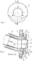
- the outer wall connection is of essentially cylindrical construction with an essentially annular combustion air chamber 1, which essentially coaxially surrounds a central, essentially cylindrical exhaust gas chamber 2.
- the two coaxial exhaust gas or combustion air chambers penetrate a wall 3, for example a caravan or mobile home, on which the outer wall connection is mounted.
- the combustion air chamber 1 and the exhaust gas chamber 2 continue to the rear in connecting pieces 17 and 18 for pipes or hoses forming the combustion air or exhaust gas duct.
- a substantially circular cover 6 is fastened by means of screws 5 parallel to the wall 3, the diameter of which is larger than the outside diameter of the combustion air chamber 1 and the between itself and the wall 3 or a mounting flange 19 for the outer wall connection defines a radially outwardly open annular space 7, in which the combustion air chamber opens with an annular, only interrupted by the webs 4 inlet opening 8, the plane of which is substantially parallel to the plane of the wall 3 runs.
- the exhaust gas chamber 2 passes through the cover 6 essentially centrally and coaxially.
- the opening 9, through which the exhaust gas emerges from the exhaust gas chamber 2, is located in the lower region of the jacket of the cylindrical exhaust gas chamber 2 projecting over the cover 6 on the outside of the cover 6.
- the exhaust gas chamber 2 is closed on the outside at the end by an end wall 10 which is sunk like a funnel.
- an end wall 10 which is sunk like a funnel.
- the exhaust gas outlet opening 9 is separated from the room wall endangered by the hot gases and at the same time additionally shielded by the cover 6.
- the combustion air can flow into the combustion air chamber 1 from all sides around the axis of the outer wall connection. Due to the described arrangement and configuration of the combustion air inlet opening 8 and the exhaust gas outlet opening 9, operational disruptions caused by wind from all directions, in particular airstream, are also eliminated. especially as a result of a pushing back of the exhaust gas into the exhaust gas chamber or also a vortex formation that impedes the intake of combustion air or an intake of one's own exhaust gases.
Landscapes
- Engineering & Computer Science (AREA)
- Chemical & Material Sciences (AREA)
- Combustion & Propulsion (AREA)
- Mechanical Engineering (AREA)
- General Engineering & Computer Science (AREA)
- Housings, Intake/Discharge, And Installation Of Fluid Heaters (AREA)
Abstract
Description
- Die Erfindung betrifft einen Außenwandanschluß gemäß dem Oberbegriff des Patentanspruchs 1.
- Ein Außenwandanschluß dieser Art ist aus der DE-OS 30 25 441 bekannt. Bei diesem bekannten Außenwandanschluß liegen Abgaskammer und Verbrennungsluftkammer übereinander, die Abgaskammer oberhalb der Verbrennungsluftkammer, wobei die Abgasaustrittsöffnung sowie die Verbrennungslufteintrittsöffnung beide im Nahbereich der Wand liegen, in der der Außenwandanschluß montiert ist.
- Der bekannte Außenwandanschluß ist strömungsmäßig hinsichtlich der Trennung von angesaugter Verbrennungsluft und ausgestoßenem Abgas, insbesondere bei Windeinfall schräg von oben nicht völlig zufriedenstellend, und vor allem kann das wandnah ausströmende Abgas aufgrund seiner Temperatur zu Schädigungen der Wandoberfläche, insbesondere wenn diese lackiert oder aus Kunststoff ist, führen.
- Aufgabe der Erfindung ist daher die Schaffung eines Außenwandkastens der eingangs genannten Art, bei welchem unter gleichzeitiger Verbesserung der Strömungsverhältnisse ein verbesserter Schutz der Oberfläche der Wand, in der der Außenwandanschluß montiert ist, vor den heißen Abgasen gewährleistet ist.
- Diese Aufgabe wird erfindungsgemäß durch einen Außenwandanschluß gelöst, wie er im Patentanspruch 1 gekennzeichnet ist.
- Vorteilhafte Weiterbildungen der Erfindung sind Gegenstand der Unteransprüche.
- Im folgenden wird eine bevorzugte Ausführungsform der Erfindung anhand der beigefügten Zeichnung beschrieben. Auf dieser zeigt
- Fig. 1 den Außenwandanschluß in einer Ansicht von vorne, und
- Fig. 2 den Außenwandanschluß in einem Längsschnitt längs Linie A-A der Fig. 1.
- Wie aus den Figuren ersichtlich, ist der Außenwandanschluß von im wesentlichen zylindrischem Aufbau mit einer im wesentlichen ringförmigen Verbrennungsluftkammer 1, welche eine zentrale im wesentlichen zylindrische Abgaskammer 2 im wesentlichen koaxial umgibt. Die beiden koaxialen Abgas- bzw. Verbrennungsluftkammern durchsetzen eine Wand 3, beispielsweise eines Wohnwagens oder Wohnmobils, an dem der Außenwandanschluß montiert ist. Die Verbrennungsluftkammer 1 und die Abgaskammer 2 setzen sich nach hinten in Anschlußstutzen 17 bzw. 18 für den Verbrennungsluft- bzw. Abgaskanal bildende Rohre oder Schläuche fort.
- In der Verbrennungsluftkammer 1 befinden sich drei in gleichem Winkelabstand verteilte Stege 4, von denen einer in Fig. 2 im Schnitt liegt. An den Stegen 4 ist mittels Schrauben 5 parallel zur Wand 3 eine im wesentlichen kreisförmige Abdeckung 6 befestigt, deren Durchmesser größer als der Außendurchmesser der Verbrennungsluftkammer 1 ist und die zwischen sich und der Wand 3 bzw. einem Befestigungsflansch 19 für den Außenwandanschluß einen radial nach außen offenen Ringraum 7 definiert, in dem die Verbrennungsluftkammer mit einer ringförmigen, nur von den Stegen 4 unterbrochenen Eintrittsöffnung 8 mündet, deren Ebene im wesentlichen parallel zur Ebene der Wand 3 verläuft.
- Die Abgaskammer 2 durchsetzt die Abdeckung 6 im wesentlichen zentral und koaxial. Die Öffnung 9, über die das Abgas aus der Abgaskammer 2 austritt, befindet sich im unteren Bereich des über die Abdeckung 6 herausragenden Mantels der zylindrischen Abgaskammer 2 auf der Außenseite der Abdeckung 6. Die Abgaskammer 2 ist außen stirnseitig durch eine Stirnwand 10 abgeschlossen, die trichterartig eingesenkt ist. Hierdurch wird bei auf die Stirnwand 10 stehendem Wind dieser in einer Weise abgelenkt, die sich günstig auf die Strömungsrichtung des Abgases weg von der Raumwand 3 auswirkt. Die Ablenkung des Abgases in eine Richtung mit stärkerer axialer Komponente wird ferner durch eine von der Abdeckung 6 in axialer Richtung abragende und unterhalb der Austrittsöffnung 9 befindliche Lippe 13 gefördert. Der Außenrand der Abdeckung 6 ist zur Raumwand 3 hin abgebogen, was den Ringraum 7 und damit die Eintrittsöffnung 8 für die Verbrennungsluft zusätzlich abschirmt.
- Mit dem beschriebenen Aufbau des Außenwandanschlusses ist die Abgasaustrittsöffnung 9 von der durch die heißen Gase gefährdeten Raumwand abgesetzt und gleichzeitig durch die Abdeckung 6 zusätzlich abgeschirmt. Gleichzeitig kann die Verbrennungsluft von allen Seiten um die Achse des Außenwandanschlusses herum in die Verbrennungsluftkammer 1 einströmen. Durch die beschriebene Anordnung und Ausgestaltung der Verbrennungslufteintrittsöffnung 8 und der Abgasaustrittsöffnung 9 sind ferner Betriebsstörungen durch Wind aus allen vorkommenden Richtungen, insbesondere Fahrtwind, vor allem als Folge eines Zurückdrückens des Abgases in die Abgaskammer oder auch einer Wirbelbildung, die das Ansaugen von Verbrennungsluft behindern, oder eines Ansaugens der eigenen Abgase, vermieden.
Claims (4)
- Außenwandanschluß für einen Verbrennungsluft- und Abgaskanal eines mit einem Brennersystem arbeitenden Geräts, wie insbesondere in einem fahrbaren Raum aufgestellten Heizgeräts, Kühlschranks oder dergleichen, wobei der Außenwandanschluß in einem Durchbruch einer Wand (3) des Raumes anbringbar ist und eine an den Abgaskanal anschließende Abgaskammer (2), aus der über eine Austrittsöffnung (9) das Abgas ins Freie gelangt, sowie eine an den Verbrennungsluftkanal anschließende Verbrennungsluftkammer (1), in die über eine Eintrittsöffnung (8) Verbrennungsluft eintritt, aufweist, dadurch gekennzeichnet, daß die Eintrittsöffnung (8) in einem bei angebrachtem Außenwandanschluß zwischen der Wand (3) und einer im Abstand von der Wand liegenden scheibenartigen Abdeckung (6) ausgebildeten radial nach außen offenen Ringraum (7) liegt, der die Abgaskammer (2) umgibt, und daß die Austrittsöffnung (9) in einem auf der Außenseite der Abdeckung (6) liegenden Teil der Abgaskammer (2) nach unten gerichtet ausgebildet ist.
- Außenwandanschluß nach Anspruch 1, dadurch gekennzeichnet, daß die Eintrittsöffnung (8) die Abgaskammer (2) ringförmig umgibt.
- Außenwandanschluß nach Anspruch 1 oder 2, dadurch gekennzeichnet, daß auf der Abdeckung (6) im Abstand von der und unterhalb der Austrittsöffnung (9) eine den Abgasstrom von der Abdeckung (6) weg ablenkende Lippe (13) vorgesehen ist.
- Außenwandanschluß nach einem der vorstehenden Ansprüche, dadurch gekennzeichnet, daß die Abgaskammer (2) außen durch eine konisch eingesenkte Stirnwand (10) abgeschlossen ist.
Applications Claiming Priority (2)
| Application Number | Priority Date | Filing Date | Title |
|---|---|---|---|
| DE4326065A DE4326065A1 (de) | 1993-08-03 | 1993-08-03 | Außenwandanschluß |
| DE4326065 | 1993-08-03 |
Publications (3)
| Publication Number | Publication Date |
|---|---|
| EP0637719A2 true EP0637719A2 (de) | 1995-02-08 |
| EP0637719A3 EP0637719A3 (de) | 1995-08-09 |
| EP0637719B1 EP0637719B1 (de) | 1998-03-18 |
Family
ID=6494373
Family Applications (1)
| Application Number | Title | Priority Date | Filing Date |
|---|---|---|---|
| EP94112044A Expired - Lifetime EP0637719B1 (de) | 1993-08-03 | 1994-08-02 | Aussenwandanschluss |
Country Status (2)
| Country | Link |
|---|---|
| EP (1) | EP0637719B1 (de) |
| DE (2) | DE4326065A1 (de) |
Cited By (1)
| Publication number | Priority date | Publication date | Assignee | Title |
|---|---|---|---|---|
| WO2020038921A1 (de) * | 2018-08-21 | 2020-02-27 | Truma Gerätetechnik GmbH & Co. KG | Endseitige leitungsanordnung für ein heizgerät eines bewohnbaren fahrzeugs |
Families Citing this family (2)
| Publication number | Priority date | Publication date | Assignee | Title |
|---|---|---|---|---|
| DE19751382A1 (de) * | 1997-11-20 | 1999-05-27 | Pepesoft Peter Eyssel Datentec | Absaugvorrichtung für Ofendämpfe |
| DE102024107997A1 (de) * | 2024-03-20 | 2025-09-25 | Truma Gerätetechnik GmbH & Co. KG | Wandkaminaufsatz für eine Heizeinrichtung eines Fahrzeugs |
Family Cites Families (3)
| Publication number | Priority date | Publication date | Assignee | Title |
|---|---|---|---|---|
| US3552377A (en) * | 1969-03-04 | 1971-01-05 | Empire Stove Co | Conduit assembly |
| FR2298062A1 (fr) * | 1975-01-17 | 1976-08-13 | Leblanc Sa E L M | Ventouse pour appareil de production d'eau chaude ou de chauffage |
| US4757802A (en) * | 1987-09-18 | 1988-07-19 | The Field Controls Company | Power venter |
-
1993
- 1993-08-03 DE DE4326065A patent/DE4326065A1/de not_active Ceased
-
1994
- 1994-08-02 EP EP94112044A patent/EP0637719B1/de not_active Expired - Lifetime
- 1994-08-02 DE DE59405455T patent/DE59405455D1/de not_active Expired - Lifetime
Cited By (3)
| Publication number | Priority date | Publication date | Assignee | Title |
|---|---|---|---|---|
| WO2020038921A1 (de) * | 2018-08-21 | 2020-02-27 | Truma Gerätetechnik GmbH & Co. KG | Endseitige leitungsanordnung für ein heizgerät eines bewohnbaren fahrzeugs |
| CN112638673A (zh) * | 2018-08-21 | 2021-04-09 | 特鲁玛杰拉特技术有限公司 | 用于可居住交通工具的加热器的末端管道装置 |
| AU2019323649B2 (en) * | 2018-08-21 | 2021-09-30 | Truma Gerätetechnik GmbH & Co. KG | End line assembly for a heating device of a vehicle fit for habitation |
Also Published As
| Publication number | Publication date |
|---|---|
| EP0637719A3 (de) | 1995-08-09 |
| DE4326065A1 (de) | 1995-02-09 |
| DE59405455D1 (de) | 1998-04-23 |
| EP0637719B1 (de) | 1998-03-18 |
Similar Documents
| Publication | Publication Date | Title |
|---|---|---|
| EP0250749B1 (de) | Düseneinrichtung für eine Klimaanlage | |
| DE1451413A1 (de) | Tragbarer Raumheizapparat | |
| DE1924873U (de) | Ventilator, insbesondere abluftventilator fuer raeume. | |
| DE69907054T2 (de) | Entlüftungsrohrauslass eines Getriebegehäuses | |
| EP0589300B1 (de) | Radialgebläse | |
| DE69713561T2 (de) | Küchenventilator | |
| DE4236674A1 (de) | Luftführungsgehäuse für Kraftfahrzeuge | |
| DE2851178A1 (de) | Fahrzeugbelueftungsvorrichtung | |
| DE10230044A1 (de) | Schalldämpfer | |
| EP0637719A2 (de) | Aussenwandanschluss | |
| DE102006005543B4 (de) | Flugzeugklimatisierungssystem mit Zyklonausströmern | |
| DE3723389A1 (de) | Hochfrequenzventilator | |
| DE19753617B4 (de) | Vorrichtung zur Heizung, Belüftung und/oder Klimatisierung, insbesondere für den Fahrgastraum eines Kraftfahrzeugs | |
| EP0128485A2 (de) | Fussbodenauslass für Lüftungs- und Klimaanlagen | |
| DE19743591C2 (de) | Vorrichtung zur Stabilisierung der Triebwerks-Einlaufströmung bei Triebwerks-Standläufen | |
| EP0211150B1 (de) | Drallauslass | |
| DE69100459T2 (de) | Endauslass für Raumlüftungsanlagen. | |
| EP0897087B1 (de) | Backofen mit Kühlluftgebläse | |
| DE19709193B4 (de) | Radialventilator | |
| DE102014102146A1 (de) | Luftansaugvorrichtung eines Kraftfahrzeugklimagerätes | |
| DE102006046750B4 (de) | Luftansaug-Geräuschdämpfer mit Wasserabscheidung | |
| DE4312825C1 (de) | Anordnung zur Luftzufuhr bei einem Radialgebläse oder dergleichen | |
| AT410057B (de) | Gehäuse für eine lufttechnische einrichtung | |
| DE2917094B1 (de) | Vorrichtung zur Schalldaemmung in einem Staubsauger | |
| DE1505278A1 (de) | Belueftungsvorrichtung fuer Kraftfahrzeugkarosserien |
Legal Events
| Date | Code | Title | Description |
|---|---|---|---|
| PUAI | Public reference made under article 153(3) epc to a published international application that has entered the european phase |
Free format text: ORIGINAL CODE: 0009012 |
|
| AK | Designated contracting states |
Kind code of ref document: A2 Designated state(s): BE DE FR GB IT NL SE |
|
| PUAL | Search report despatched |
Free format text: ORIGINAL CODE: 0009013 |
|
| AK | Designated contracting states |
Kind code of ref document: A3 Designated state(s): BE DE FR GB IT NL SE |
|
| 17P | Request for examination filed |
Effective date: 19960209 |
|
| 17Q | First examination report despatched |
Effective date: 19970212 |
|
| GRAG | Despatch of communication of intention to grant |
Free format text: ORIGINAL CODE: EPIDOS AGRA |
|
| GRAG | Despatch of communication of intention to grant |
Free format text: ORIGINAL CODE: EPIDOS AGRA |
|
| GRAH | Despatch of communication of intention to grant a patent |
Free format text: ORIGINAL CODE: EPIDOS IGRA |
|
| GRAH | Despatch of communication of intention to grant a patent |
Free format text: ORIGINAL CODE: EPIDOS IGRA |
|
| GRAA | (expected) grant |
Free format text: ORIGINAL CODE: 0009210 |
|
| ITF | It: translation for a ep patent filed | ||
| AK | Designated contracting states |
Kind code of ref document: B1 Designated state(s): BE DE FR GB IT NL SE |
|
| GBT | Gb: translation of ep patent filed (gb section 77(6)(a)/1977) |
Effective date: 19980323 |
|
| REF | Corresponds to: |
Ref document number: 59405455 Country of ref document: DE Date of ref document: 19980423 |
|
| ET | Fr: translation filed | ||
| RAP2 | Party data changed (patent owner data changed or rights of a patent transferred) |
Owner name: TRUMA GERAETETECHNIK GMBH & CO. |
|
| NLT2 | Nl: modifications (of names), taken from the european patent patent bulletin |
Owner name: TRUMA GERAETETECHNIK GMBH & CO. |
|
| PGFP | Annual fee paid to national office [announced via postgrant information from national office to epo] |
Ref country code: BE Payment date: 19980831 Year of fee payment: 5 |
|
| NLXE | Nl: other communications concerning ep-patents (part 3 heading xe) |
Free format text: PAT. BUL. 05/98 PAGE 645: CORR.: TRUMA GERAETETECHNIK GMBH & CO. |
|
| PLBE | No opposition filed within time limit |
Free format text: ORIGINAL CODE: 0009261 |
|
| STAA | Information on the status of an ep patent application or granted ep patent |
Free format text: STATUS: NO OPPOSITION FILED WITHIN TIME LIMIT |
|
| 26N | No opposition filed | ||
| PG25 | Lapsed in a contracting state [announced via postgrant information from national office to epo] |
Ref country code: BE Free format text: LAPSE BECAUSE OF NON-PAYMENT OF DUE FEES Effective date: 19990831 |
|
| BERE | Be: lapsed |
Owner name: PHILIPP KREIS G.M.B.H. & CO. TRUMA-GERATEBAU Effective date: 19990831 |
|
| REG | Reference to a national code |
Ref country code: GB Ref legal event code: IF02 |
|
| PGFP | Annual fee paid to national office [announced via postgrant information from national office to epo] |
Ref country code: NL Payment date: 20080827 Year of fee payment: 15 |
|
| PGFP | Annual fee paid to national office [announced via postgrant information from national office to epo] |
Ref country code: SE Payment date: 20080825 Year of fee payment: 15 |
|
| REG | Reference to a national code |
Ref country code: NL Ref legal event code: V1 Effective date: 20100301 |
|
| PG25 | Lapsed in a contracting state [announced via postgrant information from national office to epo] |
Ref country code: NL Free format text: LAPSE BECAUSE OF NON-PAYMENT OF DUE FEES Effective date: 20100301 |
|
| PG25 | Lapsed in a contracting state [announced via postgrant information from national office to epo] |
Ref country code: SE Free format text: LAPSE BECAUSE OF NON-PAYMENT OF DUE FEES Effective date: 20090803 |
|
| PGFP | Annual fee paid to national office [announced via postgrant information from national office to epo] |
Ref country code: DE Payment date: 20130827 Year of fee payment: 20 |
|
| PGFP | Annual fee paid to national office [announced via postgrant information from national office to epo] |
Ref country code: GB Payment date: 20130829 Year of fee payment: 20 Ref country code: FR Payment date: 20130828 Year of fee payment: 20 |
|
| PGFP | Annual fee paid to national office [announced via postgrant information from national office to epo] |
Ref country code: IT Payment date: 20130805 Year of fee payment: 20 |
|
| REG | Reference to a national code |
Ref country code: DE Ref legal event code: R071 Ref document number: 59405455 Country of ref document: DE |
|
| REG | Reference to a national code |
Ref country code: GB Ref legal event code: PE20 Expiry date: 20140801 |
|
| PG25 | Lapsed in a contracting state [announced via postgrant information from national office to epo] |
Ref country code: DE Free format text: LAPSE BECAUSE OF EXPIRATION OF PROTECTION Effective date: 20140805 |
|
| PG25 | Lapsed in a contracting state [announced via postgrant information from national office to epo] |
Ref country code: GB Free format text: LAPSE BECAUSE OF EXPIRATION OF PROTECTION Effective date: 20140801 |