EP3839498B1 - Flüssigkeitschromatographiesäule - Google Patents
Flüssigkeitschromatographiesäule Download PDFInfo
- Publication number
- EP3839498B1 EP3839498B1 EP20214728.6A EP20214728A EP3839498B1 EP 3839498 B1 EP3839498 B1 EP 3839498B1 EP 20214728 A EP20214728 A EP 20214728A EP 3839498 B1 EP3839498 B1 EP 3839498B1
- Authority
- EP
- European Patent Office
- Prior art keywords
- filter
- column
- retaining member
- spacer
- pore size
- Prior art date
- Legal status (The legal status is an assumption and is not a legal conclusion. Google has not performed a legal analysis and makes no representation as to the accuracy of the status listed.)
- Active
Links
Images


Classifications
-
- B—PERFORMING OPERATIONS; TRANSPORTING
- B01—PHYSICAL OR CHEMICAL PROCESSES OR APPARATUS IN GENERAL
- B01D—SEPARATION
- B01D36/00—Filter circuits or combinations of filters with other separating devices
- B01D36/02—Combinations of filters of different kinds
-
- G—PHYSICS
- G01—MEASURING; TESTING
- G01N—INVESTIGATING OR ANALYSING MATERIALS BY DETERMINING THEIR CHEMICAL OR PHYSICAL PROPERTIES
- G01N30/00—Investigating or analysing materials by separation into components using adsorption, absorption or similar phenomena or using ion-exchange, e.g. chromatography or field flow fractionation
- G01N30/02—Column chromatography
- G01N30/60—Construction of the column
- G01N30/6004—Construction of the column end pieces
- G01N30/603—Construction of the column end pieces retaining the stationary phase, e.g. Frits
-
- B—PERFORMING OPERATIONS; TRANSPORTING
- B01—PHYSICAL OR CHEMICAL PROCESSES OR APPARATUS IN GENERAL
- B01D—SEPARATION
- B01D29/00—Filters with filtering elements stationary during filtration, e.g. pressure or suction filters, not covered by groups B01D24/00 - B01D27/00; Filtering elements therefor
- B01D29/50—Filters with filtering elements stationary during filtration, e.g. pressure or suction filters, not covered by groups B01D24/00 - B01D27/00; Filtering elements therefor with multiple filtering elements, characterised by their mutual disposition
- B01D29/56—Filters with filtering elements stationary during filtration, e.g. pressure or suction filters, not covered by groups B01D24/00 - B01D27/00; Filtering elements therefor with multiple filtering elements, characterised by their mutual disposition in series connection
-
- B—PERFORMING OPERATIONS; TRANSPORTING
- B01—PHYSICAL OR CHEMICAL PROCESSES OR APPARATUS IN GENERAL
- B01D—SEPARATION
- B01D36/00—Filter circuits or combinations of filters with other separating devices
-
- G—PHYSICS
- G01—MEASURING; TESTING
- G01N—INVESTIGATING OR ANALYSING MATERIALS BY DETERMINING THEIR CHEMICAL OR PHYSICAL PROPERTIES
- G01N30/00—Investigating or analysing materials by separation into components using adsorption, absorption or similar phenomena or using ion-exchange, e.g. chromatography or field flow fractionation
- G01N30/02—Column chromatography
- G01N30/60—Construction of the column
-
- B—PERFORMING OPERATIONS; TRANSPORTING
- B01—PHYSICAL OR CHEMICAL PROCESSES OR APPARATUS IN GENERAL
- B01D—SEPARATION
- B01D2325/00—Details relating to properties of membranes
- B01D2325/02—Details relating to pores or porosity of the membranes
- B01D2325/0283—Pore size
Definitions
- JP-A Japanese Patent Application Laid-Open
- H02-262054 describes a high-speed liquid chromatography filter in which a coupling member is fitted over a column body so as to house a column filter in a space in the coupling member.
- the column filter is configured including an outer filter layer with a large pore size, and an inner filter layer with a small pore size.
- Filter devices that include plural filters with different pore sizes to each other are employed in order to prevent filter clogging over a long period of time. However, even in cases in which plural filters with different pore sizes are employed, filter clogging may still occur in a short period of time, requiring filter replacement.
- US 4551249 A discloses a chromatography column.
- WO 2008/014237 A2 discloses a prefilter element for a continuous flow system such as a liquid chromatography cartridge.
- JP H02 262054 A discloses a filter device for a liquid chromatograph, wherein the downstream filter has a smaller pore size than the upstream filter.
- JP 2007/127433 A discloses a column for liquid chromatography having a sealing member formed between a first frit and a second frit, the frits having filters comprising different pore sizes.
- An object of the present invention is to suppress filter clogging in a configuration including plural filters.
- the second filter that is fitted inside the second retaining member has a smaller pore size than the first filter that is fitted inside the first retaining member.
- the second retaining member is disposed downstream of the first filter, and so the second filter is also disposed downstream of the first filter.
- the spacer is disposed between the first retaining member and the second retaining member.
- the spacer maintains the non-contact state between the first filter and the second filter. Since the first filter and the second filter do not contact each other, a contact portion with holes that are smaller than the pore size of the first filter and the pore size of the second filter is not formed. Thus, foreign material that is smaller than the pore sizes of these filters is suppressed from becoming trapped at the portion between the first filter and the second filter, such that clogging is suppressed.
- the spacer includes the first contact portion that contacts the first filter.
- the first contact portion may be provided around the entire circumference of an inner ring of the spacer.
- the first contact portion may be provided in a ring shape by setting an internal diameter of the spacer smaller an internal diameter of the first retaining member.
- the ring shaped first contact portion can be provided simply by setting the internal diameter of the spacer smaller than the internal diameter of the first retaining member, such that there is no need to form the spacer in a complex shape.
- the spacer When the first contact portion protrudes from a portion of the inner ring circumference of the spacer toward the radial direction inside, the spacer is not provided around the entire inner circumference of the spacer. This enables a greater flow path area at the radial direction inside of the spacer, namely a greater area allowing a filtration subject to pass through, to be secured.
- the spacer is employed as a column including a column body that separates a component in a sample being filtered as the filtration subject filtered by the filter device passes through, a decrease in separation precision of the component in the sample in the column body can be suppressed.
- the first filter and the first retaining member may both be made from resin.
- the first filter and the first retaining member are both made from resin, the first filter can easily be fitted into and retained by the first retaining member.
- the third filter that has a larger pore size than that of the first filter enables foreign material with a large particle size to be removed from the filtration subject.
- the third filter is preferably thinner than the first filter.
- the third filter would have a larger space formed at the inside of the filter.
- the third filter by setting the third filter with the thinner thickness, spreading out that occurs as eluent and sample flow through the space inside the third filter can be kept to a minimum.
- the third filter is preferably a depth filter.
- a depth filter traps foreign material not only at the surface but also inside the filter, such that clogging is less liable to occur.
- the third filter preferably contacts a filtration face of the first filter.
- the third filter is supported by the first filter, thereby enabling slipping and deformation of the third filter to be suppressed.
- the filter device suppresses filter clogging. Moreover, a component in the sample from which the foreign material has been removed by the filter device can be separated by the column body.
- a liquid chromatography device as claimed in claim 10. The liquid chromatography device is configured including the above-described column, an eluent supply device configured to supply an eluent to the column to separate the component, and a detection device configured to detect the component of the sample separated in the column.
- the above-described column provided with any one of the above-described filter devices is included. Filter clogging is thereby suppressed by the filter device.
- a component in the sample in the column can be separated by supplying the eluent to the column using the eluent supply device. The separated sample component can be detected by the detection device.
- the present invention enables filter clogging in a configuration including plural filters to be suppressed.
- the liquid chromatography device provided with the filter device is employed to measure the concentration of glycated hemoglobin (HbA1c) in whole blood.
- the measurement subject is not limited thereto, and moreover the filter device may be applied to devices other than the liquid chromatography device.
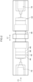
- a blood collection tube 16 is set in a device body 14 of a liquid chromatography device 12.
- the liquid chromatography device 12 is capable of automatically measuring the concentration of glycated hemoglobin (HbA1c) in whole blood.
- the device body 14 of the liquid chromatography device 12 includes plural (five in the example illustrated in Fig. 1 ) eluent bottles 18A, 18B, 18C, 18D, 18E.
- the eluent bottles 18A to 18E hold eluents A to E to be supplied to an analysis column 30, described later.
- Each of the eluents has a different composition, component ratio, acidity level, osmotic pressure, or the like, according to the purpose.
- the device body 14 further includes a sample preparation unit 20, an analysis unit 24, and a light measuring unit 26.
- the nozzle 22 is capable of sucking in and expelling liquid, and may be applied to various liquids, in particular a blood sample from the blood collection tube 16.
- the nozzle 22 can use suction to take a sample of the liquid, and can then expel the liquid.
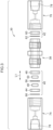
- the analysis unit 24 includes the analysis column 30, a manifold 32, a liquid feeding pump 34, and an injection valve 36.
- the analysis column 30 includes a substantially circular cylinder shaped column body 38, and an upstream filter structure 40 and a downstream filter structure 42, respectively provided at the two axial direction (length direction, arrow L1 direction) ends of the column body 38.
- the upstream filter structure 40 is an example of a "filter device”. A sample flows through the inside of the analysis column 30 in the arrow F1 direction. "Upstream” and “downstream” refer to upstream and whole blood downstream in this flow direction.
- a filler is retained inside the column body 38 in order to cause selective adsorption of hemoglobin in the sample.
- a methacrylic acid/methacrylic acid ester copolymer may be employed as the filler.
- the analysis unit 24 controls adsorption and desorption of biogenic components by the filler in the analysis column 30, and supplies various biogenic components separated in the analysis column 30 to the light measuring unit 26.
- the analysis unit 24 is set to a temperature in the region of 40°C.
- the manifold 32 is connected to the eluent bottles 18A, 18B, 18C, 18D, 18E via respective tubes 80A to 80E, and is connected to the injection valve 36 by a tube 84 with the liquid feeding pump 34 interposed between the manifold 32 and the injection valve 36.
- the manifold 32 switches internal valves so as to selectively supply eluent to the analysis column 30 from a specific eluent bottle out of the plural eluent bottles 18A to 18E.
- the liquid feeding pump 34 is provided partway along the tube 84, and imparts a motive force in order to move the eluent to the injection valve 36.
- the injection valve 36 includes plural entry ports and exit ports (not illustrated in the drawings), and is capable of taking an introduction sample of a fixed quantity, and of introducing such an introduction sample into the analysis column 30.
- An injection loop 64 is connected to the injection valve 36.
- the injection loop 64 is capable of retaining a fixed quantity (for example several ⁇ L) of liquid. Switching the injection valve 36 as appropriate enables selection of either a state in which the injection loop 64 is in communication with the dilution tank 28 and the introduction sample is supplied from the dilution tank 28 to the injection loop 64, or a state in which the injection loop 64 is in communication with the analysis column 30 via a tube 85 and the introduction sample is introduced to the analysis column 30 from the injection loop 64.
- a six-way valve may be employed as the injection valve 36.
- the light measuring unit 26 is connected to a waste liquid tank 88 via a tube 87. Liquid discharged from the analysis column 30 is discarded in the waste liquid tank 88. The light measuring unit 26 optically detects the hemoglobin contained in the eluent that has passed through the analysis column 30.
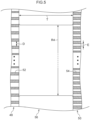
- the upstream filter structure 40 of the analysis column 30 includes a first retaining member 44 and a second retaining member 46, as illustrated in Fig. 3 and Fig. 4 .
- the first retaining member 44 is a hollow ring-shaped member, and a first filter 48 is retained in a hollow portion at the radial direction inside of the first retaining member 44.
- the second retaining member 46 is a hollow ring-shaped member that has substantially the same external diameter, internal diameter, and thickness (liquid feed direction length) as the first retaining member 44.
- a second filter 50 is retained in a hollow portion at the radial direction inside of the second retaining member 46.
- the first filter 48 is disposed upstream of the second filter 50. Namely, the first filter 48 is disposed closer to the inlet of the analysis column 30.
- the first filter 48 and the second filter 50 are configured by membrane filters or sintered filters configured to trap particles on their filter surfaces. Note that the first retaining member 44 and the second retaining member 46 do not necessarily have the same thickness as each other.
- the first retaining member 44 and the second retaining member 46 have substantially the same external diameter R1, and substantially the same internal diameter R2 and thickness.
- the first retaining member 44 and the second retaining member 46 are housed snugly in internal spaces of caps 74, 76, described later.
- the first retaining member 44 and the second retaining member 46 are both made from resin.
- the first filter 48 is formed with numerous percolation holes 52, each having a specific pore size D.
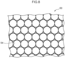
- the second filter 50 is formed with numerous percolation holes 54, each having a pore size E that is smaller than that of the percolation holes 52 in the first filter 48.
- the pore size D and the pore size E are respectively illustrated as uniform diameters in Fig. 5 , in reality variation within a specific range may be present in the pore size D and the pore size E of the first filter 48 and the second filter 50.
- the pore size E of the percolation holes 54 in the second filter 50 is smaller than the particle size of the filler in the column body 38.
- Liquid introduced to the analysis column 30 by the pump passes through the first filter 48, and then passes through the second filter 50.
- a filtration subject flows from the first filter 48 that has the larger pore size to the second filter 50 that has the smaller pore size.
- the second filter 50 that has the smaller pore size is a filter disposed downstream of the first filter 48 that has the larger pore size.
- the first filter 48 is configured by a porous resin (sintered resin product), and more specifically, is made of polyethylene.
- the resin first filter 48 is thus fitted inside and retained by friction in the hollow portion at the radial direction inside of the first retaining member 44 that is also made of resin.
- the outer side of the first filter 48 is surrounded by the first retaining member 44.
- the thickness of the first filter 48 is the same as the thickness of the first retaining member 44.
- the second filter 50 is also configured by a porous resin (sintered resin product), and more specifically, is made of polyether ether ketone.
- the resin second filter 50 is thus fitted inside and retained by friction in the hollow portion at the radial direction inside of the second retaining member 46 that is also made of resin.
- the thickness of the second filter 50 is the same as the thickness of the second retaining member 46.
- a spacer 56 is disposed between the first retaining member 44 and the second retaining member 46.
- the spacer 56 is a hollow ring-shaped member that has a specific thickness T (described in detail later).
- the spacer 56 contacts both the first retaining member 44 and the second retaining member 46.
- the spacer 56 is made of resin.
- An external diameter R3 of the spacer 56 is substantially the same as the external diameter R1 of the first retaining member 44 and the external diameter R1 of the second retaining member 46. However, an internal diameter R4 of the spacer 56 is smaller than the internal diameter R2 of the first retaining member 44.
- a radial direction inside portion of the spacer 56, more specifically a portion of the spacer 56 that is positioned further toward the radial direction inside than the internal diameter R2 of the first retaining member 44, is positioned further toward the inside than an inner ring edge (a radial direction inside edge of the ring shaped portion) of the first retaining member 44, and is in contact with a downstream end face of the first filter 48.
- the downstream filter structure 42 includes a ring shaped downstream retaining member 60, and a downstream filter 62 is retained clamped between the column body 38 and the downstream retaining member 60.
- Numerous percolation holes formed in the downstream filter 62 with a specific pore size have a pore size smaller than the particle size of the filler, such that the downstream filter 62 prevents the filler inside the column body 38 from being discharged to the exterior.
- a third filter 66 is disposed further upstream than the upstream filter structure 40.
- the third filter 66 is a depth filter in which a fibrous material is interwoven so as to form a filter structure, and traps foreign material in the filtration subject not only at the filter surface but also in tortuous internal passages. This discourages clogging even if the filtration precision has dropped.
- the pore size (mesh size) of the third filter 66 is larger than the pore size of the first filter 48, and the thickness (liquid feed direction length) of the third filter 66 is thinner than that of the first filter 48 and the second filter 50.
- the first filter 48 and the second filter 50 each have a thickness of from 0.5 mm to 4 mm
- the third filter 66 has a thickness of from 0.05 mm to 0.3 mm. Since the third filter 66 is thinner than the first filter 48, spreading out that occurs as the eluent and sample flows through a space inside the third filter 66 can be kept to a minimum.
- the third filter 66 is attached to the first retaining member 44, and contacts the first filter 48 on the upstream side of the first filter 48.
- the first filter 48 configures a structure downstream of the third filter 66 that supports the third filter 66 by contacting the entire downstream face of the third filter 66.
- a filtration face of the third filter 66 is in contact with the first filter 48.
- the third filter 66 is a filter configured by a resin nonwoven fabric.
- the downstream face of the third filter 66 and the first filter 48 are in contact with one another, such that the third filter 66 is pressed against the first filter 48 by the flow of liquid, thus fixing the third filter 66. Since the third filter 66 is a depth filter with large pores, the likelihood of blocked pores arising in the first filter 48 at a contact location between the third filter 66 and the first filter 48 is low, and clogging therefore does not occur.
- the caps 74, 76 are respectively mounted to the upstream side and downstream side of the column body 38 by being screwed into place.
- the upstream filter structure 40 is retained gripped between the column body 38 and the cap 74
- the downstream filter structure 42 is retained gripped between the column body 38 and the cap 76.
- the downstream face of the second filter 50 is in contact with the filler retained in the column body 38.
- Each of the caps 74, 76 is formed with a flow path 78 through which the sample flows.
- the column body 38 and the respective filters are integrated together in order to form the analysis column 30. This enables effort required when replacing the column body 38 and the respective filters to be alleviated.
- the nozzle 22 is used to take a blood sample from the blood collection tube 16, and this blood sample is supplied to the dilution tank 28.
- a diluent solution is also supplied to the dilution tank 28 from a preparation liquid tank (not illustrated in the drawings) in order to prepare an introduction sample in the dilution tank 28.
- the introduction sample prepared in the dilution tank 28 is supplied into and retained in the injection loop 64.
- the injection valve 36 is then switched so as to introduce the sample retained in the injection loop 64 into the analysis column 30.
- components including sA1c, HbA0, and mutant Hb are adsorbed by the filler.
- the injection valve 36 is then switched as appropriate so as to sequentially supply the eluents A to E into the analysis column 30 according to a predetermined control sequence.
- the eluent containing the various types of separated hemoglobin is then discharged from the analysis column 30.
- the eluent is supplied via a tube 86 to a light measuring cell of the light measuring unit 26, and is then guided via the tube 87 to the waste liquid tank 88.
- the light measuring unit 26 light from a light source is shone consecutively on the eluent. Transmitted light that has passed through the eluent is split using a beam splitter and picked up by light receiving elements. A chromatogram is computed and obtained by a control section of the light measuring unit 26 based on the light reception results of the light receiving elements.
- the upstream filter structure 40 of the analysis column 30 of the present exemplary embodiment includes the third filter 66, the first filter 48, and the second filter 50 in sequence from the liquid feed direction upstream side.
- the filter pore size of these filters decreases on in sequence from the upstream side toward the downstream side. Accordingly, larger sized foreign material is removed in sequence from the upstream side.
- the upstream side of the column body 38 is contacted by the second filter 50, thus suppressing the filler in the column body 38 from escaping (leaking) upstream.
- the spacer 56 is disposed between the first retaining member 44 that retains the first filter 48 and the second retaining member 46 that retains the second filter 50.
- the spacer 56 creates a non-contact state between the first filter 48 and the second filter 50, such that a space is created between the first filter 48 and the second filter 50.
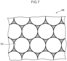
- Fig. 7 schematically illustrates the percolation holes 52 of the first filter 48.
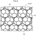
- Fig. 8 schematically illustrates the percolation holes 54 of the second filter 50. Note that although the shapes of the percolation holes 52, 54 are approximated to true circles in Fig. 7 , Fig. 8 , and Fig. 9 , described later, in reality elliptical holes or polygonal holes may also be present.
- the percolation holes 52 of the first filter 48 illustrated in Fig. 7 and the percolation holes 54 of the second filter 50 illustrated in Fig. 8 would overlap each other. As illustrated in Fig. 9 , such overlapping of the percolation holes 52 and the percolation holes 54 would form fine holes 68 each having a smaller pore size than the pore size of the percolation holes 54. Since foreign material would pass through the fine holes 68 less readily than through the percolation holes 54 due to the smaller opening area, clogging would be liable to occur at the boundary location between the first filter 48 and the second filter 50. Such clogging would reduce the effective filtration surface area of the filters, which would for example lead to a drop in flow speed and an increase in the pressure of the sample being filtered.
- the spacer 56 is used to create the non-contact state between the first filter 48 and the second filter 50. Since there is no boundary location between the first filter 48 and the second filter 50, locations (the fine holes 68 illustrated in Fig. 9 ) having a smaller opening area than the percolation holes 54 do not arise. Accordingly, the present exemplary embodiment is capable of suppressing clogging of the first filter 48 and the second filter 50. Suppressing such clogging enables a drop in the filtration performance of the filter device to be suppressed, and moreover enables increases in the lifespans of the first filter 48 and the second filter 50.
- the spacer 56 is provided with the first contact portion 58.
- the first contact portion 58 contacts the downstream face of the first filter 48. Accordingly, even if the first filter 48 is pushed toward the downstream side by the flow of the sample being filtered in the arrow F1 direction (see Fig. 4 ), the first filter 48 is suppressed from slipping or detaching from the first retaining member 44, enabling the spacing between the first filter 48 and the second filter 50 to be maintained. For example, the first filter 48 can be suppressed from moving downstream and contacting the second filter 50.
- a second contact portion (not illustrated in the drawings) is provided on the opposite face to the first contact portion 58, and the second contact portion contacts the upstream face of the second filter 50.
- the second contact portion may be omitted since the spacer 56 is upstream of the second filter 50, such a second contact portion is capable of preventing the second filter 50 from slipping or detaching from the second retaining member 46.
- the upstream filter structure 40 of the present exemplary embodiment includes the third filter 66 that is provided further upstream than the first filter 48.
- the third filter 66 covers the first filter 48, and the pore size (mesh size) of the third filter 66 is larger than the pore size D of the percolation holes 52 of the first filter 48. This enables foreign material with a relatively large particle size to be removed from the sample being filtered first, by the third filter 66. Foreign material with a smaller particle size can then removed by the first filter 48, and foreign material with an even smaller particle size can then removed by the second filter 50.
- the third filter 66 is further upstream than the first filter 48, and contacts the first filter 48.
- the first filter 48 therefore supports the third filter 66, enabling the third filter 66 to be suppressed from slipping toward the downstream side or deforming due to the flow of the sample being filtered in the arrow F1 direction.
- the third filter 66 since the third filter 66 is configured from nonwoven fabric, the third filter 66 flexes easily. However, since the third filter 66 contacts and is supported by the filtration face of the first filter 48, flexing of the third filter 66 is suppressed.
- the thickness T of the spacer 56 is not limited, as long as the thickness T is sufficient to place the first filter 48 and the second filter 50 in the non-contact state as described above.
- a lower limit for the thickness T of the spacer 56 is set with respect to the pore size D (mm) of the percolation holes 52 of the first filter 48 so as to satisfy the relationship D ⁇ 10 ⁇ T. So doing achieves a sufficient spacing between the first filter 48 and the second filter 50.
- the resulting gap enables, for example, a space in which the filtration subject that has passed through the first filter 48 can flow to be secured. This configuration is preferable since any obstruction to the flow of eluent can be suppressed even if foreign material contained in the filtration subject is trapped at the surface of the second filter 50.
- an upper limit of the thickness T of the spacer 56 is set so as to satisfy the relationship T ⁇ 0.2 mm. With increasing flow path length to the column body 38, the sample spreads out more before reaching the column body 38, resulting in decreased separation precision. However, setting the thickness T of the spacer 56 within the above range enables good separation precision to be maintained. Moreover, in the present exemplary embodiment, since the upstream filter structure 40 is employed to remove foreign material from the sample flowing into the column body 38, an increase in pressure in the column body 38 can be prevented, enabling a decrease in separation precision to be suppressed.
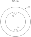
- protruding tabs 70 are formed protruding from the inner circumference of the spacer 56 toward the radial direction inside at two opposing locations.
- the internal diameter R4 of the spacer 56 is equal to the internal diameter R2 of the first retaining member 44. Accordingly, the first contact portion can be formed with a simple structure by the protruding tabs 70 protruding from the inner circumference of the spacer 56 in this manner.
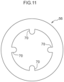
- the protruding tabs 70 of the first modified example illustrated in Fig. 10 protrude from the inner circumference of the spacer 56 toward the radial direction inside at four locations.
- the second modified example illustrated in Fig. 11 since the number of the protruding tabs 70 is greater, the effect of suppressing slipping and detachment of the first filter 48 is greater than that of the first modified example illustrated in Fig. 10 .
- the number of the protruding tabs 70 is fewer than in the second modified example illustrated in Fig.
- a bridging tab 72 is provided spanning across the diameter of the inner circumference of the spacer 56.
- the bridging tab 72 has a shape achieved by extending the two protruding tabs 70 of the first modified example illustrated in Fig. 10 in their protruding directions until they join up.
- the flow speed of the filtration subject flowing through the radial direction inside of the first retaining member 44 is faster the closer it is to a radial direction central portion thereof.
- the bridging tab 72 of the third modified example illustrated in Fig. 12 also contacts the first filter 48 at this central portion, and is thus highly effective in suppressing slipping and detachment of the first filter 48.
- the first contact portion 58 contacts the first filter 48 around its entire circumference, and is thus capable of suppressing slipping and detachment of the first filter 48 around its entire circumference. Since the first contact portion 58 can be formed simply by reducing the internal diameter R4 of the spacer 56, there is no need to form the protruding tabs 70 or the bridging tab 72 and the shape remains simple. Note that the modified examples of the first contact portion may similarly be adopted for the second contact portion. The first contact portion and the second contact portion do not have to have the same shape as each other. For example, the first contact portion 58 may have the shape described in the exemplary embodiment illustrated in Fig. 6 , whereas the second contact portion may have the shape of the first modified example illustrated in Fig. 10 .
- the materials employed for the first retaining member 44, the second retaining member 46, the first filter 48, and the second filter 50 are not limited to the resins described above, and for example some or all of these components may be configured from metal.
- the press fitting may incur some slight deformation (tightening) in order to achieve retention.
- the first retaining member 44 and the first filter 48 responds to the deformation of the other thereof, enabling a seal to be formed at a tight fitting portion between the first retaining member 44 and the first filter 48.
- the first retaining member 44 and the second retaining member 46 are both hollow ring-shaped members.
- these hollow members may each have an elliptical or polygonal outer circumference and inner circumference as viewed along the arrow F1 direction.
- these hollow members may each have a combination of a circular and a polygonal shape, such as a polygonal shaped outer side and a circular inner side. Namely, as long as they have a structure with a closed curved shape as viewed along the arrow F 1 direction, the first retaining member 44 and the second retaining member 46 are capable of respectively retaining the first filter 48 and the second filter 50 at the inside thereof.
Landscapes
- Chemical & Material Sciences (AREA)
- Chemical Kinetics & Catalysis (AREA)
- Physics & Mathematics (AREA)
- Health & Medical Sciences (AREA)
- Life Sciences & Earth Sciences (AREA)
- Analytical Chemistry (AREA)
- Biochemistry (AREA)
- General Health & Medical Sciences (AREA)
- General Physics & Mathematics (AREA)
- Immunology (AREA)
- Pathology (AREA)
- Sampling And Sample Adjustment (AREA)
- Treatment Of Liquids With Adsorbents In General (AREA)
Claims (10)
- Säule (30), umfassend:eine Filtervorrichtung (40) umfassend:einen ersten Filter (48);ein erstes Halteelement (44), das eine hohle Form aufweist, wobei der erste Filter (48) in das erste Halteelement (44) eingesetzt ist; undeinen zweiten Filter (50), der eine kleinere Porengröße als der erste Filter (48) aufweist;wobei die Säule weiter einen Säulenkörper (38) umfasst, der mit einem Füllstoff gefüllt ist, um eine in einer Probe enthaltene Komponente abzutrennen, die durch die Filtervorrichtung (40) gefiltert wird;dadurch gekennzeichnet, dass die Vorrichtung (40) Folgendes umfasst:ein zweites Halteelement (46), das dem ersten Filter (48) nachgeschaltet ist und eine hohle Form aufweist, wobei der zweite Filter (50) in das zweite Halteelement (46) eingesetzt ist; undeinen Abstandshalter (56), der eine hohle Form aufweist, der zwischen dem ersten Halteelement (44) und dem zweiten Halteelement (46) angeordnet ist, der einen berührungslosen Zustand zwischen dem ersten Filter (48) und dem zweiten Filter (50) aufrechterhält und der einen ersten Kontaktabschnitt (58) beinhaltet, der den ersten Filter (48) berührt;wobei eine Dicke T des Abstandshalters (56) in Bezug auf eine Porengröße D des ersten Filters (48) in einem Bereich liegt, der eine Beziehung D x 10 ≤ T ≤ 0,2 mm erfüllt.
- Säule (30) nach Anspruch 1, wobei der erste Kontaktabschnitt (58) in einer Ringform vorgesehen ist, indem ein Innendurchmesser des Abstandshalters (56) kleiner als ein Innendurchmesser des ersten Halteelements (44) eingestellt ist.
- Säule (30) nach Anspruch 1, wobei der erste Kontaktabschnitt (58) von einem Abschnitt eines inneren Ringumfangs des Abstandshalters (56) in eine radiale Richtung nach innen vorsteht.
- Säule (30) nach Anspruch 1, 2 oder 3, wobei der erste Filter (48) und das erste Halteelement (44) beide aus Harz hergestellt sind.
- Säule (30) nach einem der Ansprüche 1 bis 4, die weiter einen dritten Filter (66) umfasst, der dem ersten Halteelement (44) vorgeschaltet ist und eine größere Porengröße aufweist als die Porengröße des ersten Filters (48).
- Säule (30) nach Anspruch 5, wobei der dritte Filter (66) dünner ist als der erste Filter (48).
- Säule (30) nach Anspruch 5 oder 6, wobei der dritte Filter (66) ein Tiefenfilter ist.
- Säule (30) nach Anspruch 5, 6 oder 7, wobei der dritte Filter (66) eine Filtrationsfläche des ersten Filters (48) berührt.
- Säule (30) nach einem vorstehenden Anspruch, weiter umfassend:eine vorgeschaltete Filterstruktur (40), die den ersten Filter (48), das erste Halteelement (44), den zweiten Filter (50), das zweite Halteelement (46) und den Abstandshalter (56) beinhaltet; undeine Kappe (74), die so am Säulenkörper (38) montiert ist, dass die vorgeschaltete Filterstruktur (40) zwischen der Kappe (74) und dem Säulenkörper (38) eingeklemmt wird.
- Flüssigchromatographie-Vorrichtung (12) umfassend:die Säule (30) nach einem vorstehenden Anspruch;eine Eluentenzufuhrvorrichtung (32, 34, 36), die so konfiguriert ist, dass sie der Säule (30) einen Eluenten zuführt, um die Komponente abzutrennen; undeine Detektionsvorrichtung (26), die so konfiguriert ist, dass sie die in der Säule (30) abgetrennte Komponente der Probe detektiert.
Applications Claiming Priority (1)
| Application Number | Priority Date | Filing Date | Title |
|---|---|---|---|
| JP2019227009A JP7339876B2 (ja) | 2019-12-17 | 2019-12-17 | フィルタ装置、カラム及び液体クロマトグラフィ装置 |
Publications (3)
| Publication Number | Publication Date |
|---|---|
| EP3839498A1 EP3839498A1 (de) | 2021-06-23 |
| EP3839498B1 true EP3839498B1 (de) | 2025-02-05 |
| EP3839498C0 EP3839498C0 (de) | 2025-02-05 |
Family
ID=73855170
Family Applications (1)
| Application Number | Title | Priority Date | Filing Date |
|---|---|---|---|
| EP20214728.6A Active EP3839498B1 (de) | 2019-12-17 | 2020-12-16 | Flüssigkeitschromatographiesäule |
Country Status (4)
| Country | Link |
|---|---|
| US (1) | US11819786B2 (de) |
| EP (1) | EP3839498B1 (de) |
| JP (1) | JP7339876B2 (de) |
| CN (1) | CN112973266B (de) |
Families Citing this family (1)
| Publication number | Priority date | Publication date | Assignee | Title |
|---|---|---|---|---|
| JP2024017921A (ja) | 2022-07-28 | 2024-02-08 | アークレイ株式会社 | 液体クロマトグラフィーカラム |
Citations (2)
| Publication number | Priority date | Publication date | Assignee | Title |
|---|---|---|---|---|
| JPH02262054A (ja) * | 1989-03-31 | 1990-10-24 | Sekisui Chem Co Ltd | 高速液体クロマトグラフ用フィルター |
| JP2007127433A (ja) * | 2005-11-01 | 2007-05-24 | Hitachi High-Technologies Corp | 高速液体クロマトグラフ用カラム |
Family Cites Families (19)
| Publication number | Priority date | Publication date | Assignee | Title |
|---|---|---|---|---|
| US4551249A (en) * | 1984-02-29 | 1985-11-05 | Rainin Instrument Co. Inc. | Modular liquid chromatography column apparatus |
| US4565632A (en) * | 1985-01-11 | 1986-01-21 | Beckman Instruments, Inc. | Chromatographic cartridge column system |
| JPH0341763Y2 (de) * | 1985-03-18 | 1991-09-02 | ||
| JP3355681B2 (ja) * | 1993-02-15 | 2002-12-09 | 東ソー株式会社 | 液体クロマトグラフ用フィルター内蔵カラム |
| US5667676A (en) * | 1996-05-01 | 1997-09-16 | Alaska; Andrew B. | Side-packed chromatographic column |
| JP4219564B2 (ja) * | 2001-01-19 | 2009-02-04 | 株式会社資生堂 | 高速液体クロマトグラフィー用カラム |
| JP4897282B2 (ja) * | 2004-12-09 | 2012-03-14 | 積水化学工業株式会社 | 生体試料分析用の液体クロマトグラフィー用フィルタ及び生体試料の分析方法 |
| JP2006326515A (ja) * | 2005-05-27 | 2006-12-07 | Aisan Ind Co Ltd | フィルタ |
| US20080029449A1 (en) * | 2006-07-25 | 2008-02-07 | Bio-Rad Laboratories, Inc. | Graded external prefilter element for continuous-flow systems |
| WO2009123199A1 (ja) * | 2008-03-31 | 2009-10-08 | 積水化学工業株式会社 | 液体クロマトグラフィー用部材 |
| JP5458581B2 (ja) * | 2009-01-23 | 2014-04-02 | 栗田工業株式会社 | 液体クロマトグラフィ装置 |
| DE102009001756A1 (de) * | 2009-03-23 | 2009-07-30 | Agilent Technologies Inc., Santa Clara | Mehrlagige geordnete Netze als Filter in Probenseparationsvorrichtung |
| MX2012000735A (es) * | 2009-07-30 | 2012-01-27 | Hoffmann La Roche | Separador de columna de cromatografia movible. |
| JP5521218B2 (ja) * | 2010-05-18 | 2014-06-11 | 東ソー株式会社 | 液体クロマトグラフ用フィルター |
| US20140021116A1 (en) * | 2012-07-17 | 2014-01-23 | Fh Instruments, Llc | Hplc frit filter assembly |
| US20140124444A1 (en) * | 2012-11-06 | 2014-05-08 | Phenomenex, Inc. | Sintered metal fiber disks for chromatographic applications |
| JP6857604B2 (ja) * | 2015-08-25 | 2021-04-14 | 昭和電工株式会社 | 液体クロマトグラフィー用カラム及びそれを備えた液体クロマトグラフ装置 |
| JP2017146274A (ja) * | 2016-02-19 | 2017-08-24 | 栗田工業株式会社 | クロマトグラフィカラム及びその可動栓 |
| US11161065B2 (en) * | 2018-04-19 | 2021-11-02 | Waters Technologies Corporation | Filtration device for chromatographic instruments |
-
2019
- 2019-12-17 JP JP2019227009A patent/JP7339876B2/ja active Active
-
2020
- 2020-12-15 CN CN202011471590.8A patent/CN112973266B/zh active Active
- 2020-12-16 EP EP20214728.6A patent/EP3839498B1/de active Active
- 2020-12-16 US US17/123,799 patent/US11819786B2/en active Active
Patent Citations (2)
| Publication number | Priority date | Publication date | Assignee | Title |
|---|---|---|---|---|
| JPH02262054A (ja) * | 1989-03-31 | 1990-10-24 | Sekisui Chem Co Ltd | 高速液体クロマトグラフ用フィルター |
| JP2007127433A (ja) * | 2005-11-01 | 2007-05-24 | Hitachi High-Technologies Corp | 高速液体クロマトグラフ用カラム |
Also Published As
| Publication number | Publication date |
|---|---|
| US11819786B2 (en) | 2023-11-21 |
| CN112973266A (zh) | 2021-06-18 |
| US20210178296A1 (en) | 2021-06-17 |
| EP3839498A1 (de) | 2021-06-23 |
| CN112973266B (zh) | 2024-07-05 |
| JP2021096137A (ja) | 2021-06-24 |
| JP7339876B2 (ja) | 2023-09-06 |
| EP3839498C0 (de) | 2025-02-05 |
Similar Documents
| Publication | Publication Date | Title |
|---|---|---|
| US9216366B2 (en) | Liquid chromatography component | |
| EP0711183B1 (de) | Selbstentlüftende filtervorrichtung | |
| JP5868977B2 (ja) | 液体クロマトグラフィシステム用の生体適合性管 | |
| JP5833990B2 (ja) | 流体混合器アセンブリ | |
| US8733152B2 (en) | Automated analyzer with low-pressure in-line filtration | |
| EP3839498B1 (de) | Flüssigkeitschromatographiesäule | |
| WO2003061805A1 (en) | Sealed integral liquid chromatography system | |
| CN212757529U (zh) | 一次性注射式液相色谱分析液过滤装置 | |
| CN107636457A (zh) | 流路单元 | |
| US20240280546A1 (en) | Fluid supply devices for forming a filtered mobile phase for a sample separating device | |
| CN115335696B (zh) | 液相色谱用构件 | |
| EP4312024B1 (de) | Flüssigkeitschromatographiesäule | |
| US12146868B2 (en) | Pump unit and chromatograph | |
| JP2013003015A (ja) | 液体クロマトグラフィー用フィルターおよびその使用方法 | |
| JP2006138724A (ja) | 液体クロマトグラフィー用フィルター、該フィルターが一体化された液体クロマトグラフィー用カラム、該フィルターを用いた液体クロマトグラフィーシステム、及び該フィルターを用いた液体クロマトグラフィーによる測定方法 | |
| Joshi | Proper Sample Prep Ensures HPLC Success | |
| WO2020144878A1 (ja) | 液体クロマトグラフに使用されるフィルタおよび液体クロマトグラフ | |
| AU2003201392A1 (en) | Sealed integral liquid chromatography sytem |
Legal Events
| Date | Code | Title | Description |
|---|---|---|---|
| PUAI | Public reference made under article 153(3) epc to a published international application that has entered the european phase |
Free format text: ORIGINAL CODE: 0009012 |
|
| STAA | Information on the status of an ep patent application or granted ep patent |
Free format text: STATUS: THE APPLICATION HAS BEEN PUBLISHED |
|
| AK | Designated contracting states |
Kind code of ref document: A1 Designated state(s): AL AT BE BG CH CY CZ DE DK EE ES FI FR GB GR HR HU IE IS IT LI LT LU LV MC MK MT NL NO PL PT RO RS SE SI SK SM TR |
|
| STAA | Information on the status of an ep patent application or granted ep patent |
Free format text: STATUS: REQUEST FOR EXAMINATION WAS MADE |
|
| 17P | Request for examination filed |
Effective date: 20211220 |
|
| RBV | Designated contracting states (corrected) |
Designated state(s): AL AT BE BG CH CY CZ DE DK EE ES FI FR GB GR HR HU IE IS IT LI LT LU LV MC MK MT NL NO PL PT RO RS SE SI SK SM TR |
|
| STAA | Information on the status of an ep patent application or granted ep patent |
Free format text: STATUS: EXAMINATION IS IN PROGRESS |
|
| 17Q | First examination report despatched |
Effective date: 20230615 |
|
| GRAP | Despatch of communication of intention to grant a patent |
Free format text: ORIGINAL CODE: EPIDOSNIGR1 |
|
| STAA | Information on the status of an ep patent application or granted ep patent |
Free format text: STATUS: GRANT OF PATENT IS INTENDED |
|
| INTG | Intention to grant announced |
Effective date: 20240926 |
|
| GRAS | Grant fee paid |
Free format text: ORIGINAL CODE: EPIDOSNIGR3 |
|
| GRAA | (expected) grant |
Free format text: ORIGINAL CODE: 0009210 |
|
| STAA | Information on the status of an ep patent application or granted ep patent |
Free format text: STATUS: THE PATENT HAS BEEN GRANTED |
|
| AK | Designated contracting states |
Kind code of ref document: B1 Designated state(s): AL AT BE BG CH CY CZ DE DK EE ES FI FR GB GR HR HU IE IS IT LI LT LU LV MC MK MT NL NO PL PT RO RS SE SI SK SM TR |
|
| REG | Reference to a national code |
Ref country code: GB Ref legal event code: FG4D |
|
| REG | Reference to a national code |
Ref country code: CH Ref legal event code: EP |
|
| REG | Reference to a national code |
Ref country code: DE Ref legal event code: R096 Ref document number: 602020045728 Country of ref document: DE |
|
| REG | Reference to a national code |
Ref country code: IE Ref legal event code: FG4D |
|
| U01 | Request for unitary effect filed |
Effective date: 20250205 |
|
| U07 | Unitary effect registered |
Designated state(s): AT BE BG DE DK EE FI FR IT LT LU LV MT NL PT RO SE SI Effective date: 20250211 |
|
| PG25 | Lapsed in a contracting state [announced via postgrant information from national office to epo] |
Ref country code: RS Free format text: LAPSE BECAUSE OF FAILURE TO SUBMIT A TRANSLATION OF THE DESCRIPTION OR TO PAY THE FEE WITHIN THE PRESCRIBED TIME-LIMIT Effective date: 20250505 |
|
| PG25 | Lapsed in a contracting state [announced via postgrant information from national office to epo] |
Ref country code: PL Free format text: LAPSE BECAUSE OF FAILURE TO SUBMIT A TRANSLATION OF THE DESCRIPTION OR TO PAY THE FEE WITHIN THE PRESCRIBED TIME-LIMIT Effective date: 20250205 |
|
| PG25 | Lapsed in a contracting state [announced via postgrant information from national office to epo] |
Ref country code: ES Free format text: LAPSE BECAUSE OF FAILURE TO SUBMIT A TRANSLATION OF THE DESCRIPTION OR TO PAY THE FEE WITHIN THE PRESCRIBED TIME-LIMIT Effective date: 20250205 |
|
| PG25 | Lapsed in a contracting state [announced via postgrant information from national office to epo] |
Ref country code: NO Free format text: LAPSE BECAUSE OF FAILURE TO SUBMIT A TRANSLATION OF THE DESCRIPTION OR TO PAY THE FEE WITHIN THE PRESCRIBED TIME-LIMIT Effective date: 20250505 Ref country code: IS Free format text: LAPSE BECAUSE OF FAILURE TO SUBMIT A TRANSLATION OF THE DESCRIPTION OR TO PAY THE FEE WITHIN THE PRESCRIBED TIME-LIMIT Effective date: 20250605 |
|
| PG25 | Lapsed in a contracting state [announced via postgrant information from national office to epo] |
Ref country code: HR Free format text: LAPSE BECAUSE OF FAILURE TO SUBMIT A TRANSLATION OF THE DESCRIPTION OR TO PAY THE FEE WITHIN THE PRESCRIBED TIME-LIMIT Effective date: 20250205 |
|
| PG25 | Lapsed in a contracting state [announced via postgrant information from national office to epo] |
Ref country code: GR Free format text: LAPSE BECAUSE OF FAILURE TO SUBMIT A TRANSLATION OF THE DESCRIPTION OR TO PAY THE FEE WITHIN THE PRESCRIBED TIME-LIMIT Effective date: 20250506 |
|
| PG25 | Lapsed in a contracting state [announced via postgrant information from national office to epo] |
Ref country code: SM Free format text: LAPSE BECAUSE OF FAILURE TO SUBMIT A TRANSLATION OF THE DESCRIPTION OR TO PAY THE FEE WITHIN THE PRESCRIBED TIME-LIMIT Effective date: 20250205 |
|
| PG25 | Lapsed in a contracting state [announced via postgrant information from national office to epo] |
Ref country code: CZ Free format text: LAPSE BECAUSE OF FAILURE TO SUBMIT A TRANSLATION OF THE DESCRIPTION OR TO PAY THE FEE WITHIN THE PRESCRIBED TIME-LIMIT Effective date: 20250205 |
|
| PG25 | Lapsed in a contracting state [announced via postgrant information from national office to epo] |
Ref country code: SK Free format text: LAPSE BECAUSE OF FAILURE TO SUBMIT A TRANSLATION OF THE DESCRIPTION OR TO PAY THE FEE WITHIN THE PRESCRIBED TIME-LIMIT Effective date: 20250205 |
|
| PLBE | No opposition filed within time limit |
Free format text: ORIGINAL CODE: 0009261 |
|
| STAA | Information on the status of an ep patent application or granted ep patent |
Free format text: STATUS: NO OPPOSITION FILED WITHIN TIME LIMIT |
|
| PGFP | Annual fee paid to national office [announced via postgrant information from national office to epo] |
Ref country code: GB Payment date: 20251219 Year of fee payment: 6 |
|
| 26N | No opposition filed |
Effective date: 20251106 |
|
| U20 | Renewal fee for the european patent with unitary effect paid |
Year of fee payment: 6 Effective date: 20251230 |