EP3839176A1 - Sicherungsmodul für eine handhabe eines treibstangenbeschlages - Google Patents
Sicherungsmodul für eine handhabe eines treibstangenbeschlages Download PDFInfo
- Publication number
- EP3839176A1 EP3839176A1 EP20212443.4A EP20212443A EP3839176A1 EP 3839176 A1 EP3839176 A1 EP 3839176A1 EP 20212443 A EP20212443 A EP 20212443A EP 3839176 A1 EP3839176 A1 EP 3839176A1
- Authority
- EP
- European Patent Office
- Prior art keywords
- control part
- adapter
- module according
- drive
- handle
- Prior art date
- Legal status (The legal status is an assumption and is not a legal conclusion. Google has not performed a legal analysis and makes no representation as to the accuracy of the status listed.)
- Granted
Links
Images


Classifications
-
- E—FIXED CONSTRUCTIONS
- E05—LOCKS; KEYS; WINDOW OR DOOR FITTINGS; SAFES
- E05B—LOCKS; ACCESSORIES THEREFOR; HANDCUFFS
- E05B13/00—Devices preventing the key or the handle or both from being used
- E05B13/005—Disconnecting the handle
Definitions
- the invention relates to a securing module for a handle of a drive rod fitting, with a housing provided for screwing in a window, a window door or the like, with at least one drive pin provided for the arrangement between the handle and a drive gear of the drive rod fitting, with form-fitting means for optionally generating or releasing a Positive locking of the drive mandrel with a further component and with actuating means for controlling the positive locking means.
- Such a security module is, for example, from EP 2 669 452 A2 known.
- the drive mandrel is positively connected to an adapter having a flat.
- a form fit between the drive pin and the housing can optionally be created or released.
- this security module requires adapted handling because the drive pin is part of the security module.
- the rod protrudes from the housing.
- a locking device has become known in which a displaceable plate has a recess for the drive pin. In one position of the plate, a form fit with the drive pin is created, while in another position the form fit is released.
- the disadvantage here is that the plate, which is usually made of very thin sheet metal, can only support very low forces of the drive pin. With a slightly increased effort on the handle, the form fit between the plate and the drive pin can be released.
- an actuating device with a handle and a means for locking the rotational movement of the handle has become known.
- the handle is connected to a square as a drive pin.
- a locking plate with a recess can be moved into a position in which the recess creates a form fit with the square.
- the recess for the drive pin can be destroyed with a slightly increased effort on the handle.
- the invention is based on the problem of designing a security module of the type mentioned at the outset so that it can be used for various manipulations and connecting rod fittings and prevents unintentional driving of the connecting rod fitting via the handle.
- the form-locking means have a control part that is movable by the actuating means and an adapter that can be displaced with the control part and that the adapter is designed to optionally generate or release a form-fit connection of the drive mandrel with a second drive mandrel.
- the security module can be easily adapted to different handling by appropriately designing the adapter.
- the securing module can be easily adapted to different distances between the components of the connecting rod fitting.
- the adapter can also be manufactured with a specified height and strength and can thus support high forces when generating the form fit.
- the securing module forms a coupling between the drive pins, so that when the form fit is released, no forces can be transmitted from the handle to the drive rod fitting.
- the drive mandrel is usually designed as a square.
- the drive mandrel can be supported over a particularly large area by the adapter if the adapter is U-shaped, encompassing a section of the drive mandrel in one position of the control part.
- the adapter is able to create a coupling between the two drive mandrels when generating the form fit of the drive mandrel with the second drive mandrel.
- the coupling of two drive mandrels is particularly simple if the adapter is rotatably mounted in the control part and connects two ends of the drive mandrels to one another when generating the form fit.
- the adapter has a high level of strength when the height of the adapter corresponds at least to the diameter of the drive mandrel.
- the adapter helps to increase the stability of the form-locking means if the adapter is sandwiched between the control part and a bearing part connected to the control part.
- the adapter could, for example, interact directly with the drive mandrel to produce the form fit.
- the drive mandrel is usually designed as a square mandrel and has large tolerances.
- the form-locking means can be manufactured with particularly high stability if the drive pin is connected to a locking disk in a rotationally fixed manner and if the form-locking means are arranged between the locking disk and the adapter.
- a faulty coupling of the handle to the drive gear can easily be avoided according to another advantageous development of the invention if the locking disk and the adapter have projections and recesses and if the projections and recesses correspond to one another in a single rotational position of the drive pin. As a result of this design, the projections and recesses only fit together in the intended rotational position of the drive mandrel with the housing or the further drive mandrel.
- a subsequent assembly of the security module on an existing espagnolette fitting turns out to be particularly simple according to another advantageous development of the invention if screw holes for fastening the housing are aligned with a bearing plate of the handle.
- the security module has a particularly high stability when the control part surrounds the screw bores and is supported on an inner wall of the housing.
- the optional blocking or release of the form-locking means is particularly simple according to another advantageous development of the invention if the actuation means have an actuation element movably guided on the housing and if the actuation element and the control part are positively connected to one another.
- the actuating element is rotatable and protrudes with projections into a toothing of the control part.
- accidental activation of the form-locking means can be easily avoided if the movement of the actuating element is blocked in a basic position and if a manually operable securing element is arranged on the actuating element to release the blockage.
- a further avoidance of inadvertent activation of the interlocking means helps if the movement of the control part is blocked in a basic position and if a manually operated securing element is arranged on the housing to release the blockage.
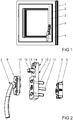
- Figure 1 shows a window with a sash 2 pivotable against a frame 1 and with a connecting rod fitting 3, shown schematically, for locking the sash 2 in the frame 1.
- the connecting rod fitting 3 can be driven by a handle 4.
- a safety module 5 is arranged between the wing 2 and the handle 4. The handle 4 can be decoupled from the connecting rod fitting 3 via the securing module 5.
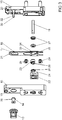
- Figure 2 shows the handle 4, the securing module 5 and a drive gear 6 of the espagnolette 3 in a perspective view before assembly. Screw holes 7 of the fuse module 5 are aligned with screw holes 8, 9 of the drive gear 6 and the handle 4.
- the handle 4 has a drive pin 10.
- a second drive pin 11 is mounted in the fuse module 5, which is coupled to the drive gear 6 in the assembled state.
- the securing module 5 has a housing 12 and an actuating element 13 which is rotatable in the housing 12 and has a securing element 14 arranged in it so that it cannot rotate.
- FIG. 3 shows the components of the fuse module 5 in an exploded view.
- the housing 12 has a housing main body 15 and a housing cover 16 that can be connected to the housing main body 15.
- a control part 17 is displaceably guided in the housing 12.
- the control part 17 has a toothing 18 for connection to the actuating element 13.
- Another securing element 19 is arranged as a push button in the housing cover 16 and, in the assembled state, interacts with a resilient hook 20 arranged in the housing base body 15.
- the hook 20 supports an edge 21 of the control part 17 and prevents its displacement.
- the securing element 19 designed as a push button
- the control part 17 is connected to a bearing part 22 in the assembled state.
- a U-shaped adapter 23 is sandwiched between the control part 17 and the bearing part 22.
- the U-shaped adapter 23 receives a section of the drive mandrel 10 of the handle 4 and a section of the second drive mandrel 11.
- a locking disk 24 is rotatably mounted in the bearing part 22.
- Locking disk 24 and adapter 23 have projections 25 and recesses 26 that correspond to one another, so that they engage in one another in only one rotational position.
- Bearing disks 27 for the second drive mandrel 11 are arranged between the housing base body 15 and the control part 17. These bearing disks 27 support the second drive mandrel 11 in a rotatable and axially immovable manner.
- screw sleeves 28, 29 are inserted, which are laterally enclosed by the control part 17 in the assembled state.
- the screw sleeves 28, 29 are inserted into the screw bores 7 from the side of the handle 4 and are locked there immovably after the securing module 5 has been attached to the drive gear 6 by connecting screws (not shown).
- the screw sleeves 28, 29 cover the heads of the connecting screws.
- the securing element 14 of the actuating element 13 is guided in the assembled state on a stationary mandrel 30 of the housing base body 15 and has tabs 31.
- the tabs 31 create a form fit with flattened areas 32 of the stationary mandrel 30.
- the form fit is released and the securing element is released by lateral compression 14 can be rotated together with the actuating element 13 in the housing 12 in order to drive the control part 17 via the toothing 18.
- a recess 33 arranged in the control part 17 has a bearing section 34 for mounting the adapter 23 and a section with support surfaces 35 for supporting the second drive mandrel 11.
- the Figures 4 and 5 the securing module 5 in longitudinal sections offset by 90 ° in relation to one another in a basic position in which the movement of the drive pin 10 of the handle 5 is coupled to the second drive pin 11.
- the coupling is achieved in that the projections 25 of the locking disk 24 engage in the recesses 26 of the adapter 23, the one drive mandrel 10 with the locking disk 24 and the adapter 23 and the second drive mandrel 11 is non-rotatably connected to the adapter 23.
- This allows the in Figure 1 Drive the espagnolette 3 shown by actuating the handle 4.
- the drive pin 10 of the handle 4 which is connected to the locking disk 24 in the assembled state, is not shown to simplify the drawing.
- the adapter 23 moves out of the range of motion of the second drive mandrel 11.
- This position is in FIG Figures 6 and 7 shown in the respective sectional views.
- the second drive mandrel 11 is held in a form-fitting manner by the support surfaces 35 of the control part 17.
- the second drive mandrel 11 cannot be rotated and thus the drive rod fitting 3 is held in its position.
- the projections of the locking disk are moved out of their engagement from the recesses of the adapter.
- the actuating element 13 is held in its position by the securing element 14 in the rotary position shown.
- the control part 17 is held in its position by the hook 20.
- the securing element 14 of the actuating element 13 is to be released by pressing it together and the hook 20 is to be depressed by the securing element 19 designed as a push button.
- the actuating element 13 can then be rotated and the control part 17 can be moved over the toothing 18 in order to return to the Figures 4 and 5 to return to the position shown.
Landscapes
- Lock And Its Accessories (AREA)
Abstract
Description
- Die Erfindung betrifft ein Sicherungsmodul für eine Handhabe eines Treibstangenbeschlages, mit einem zur Verschraubung in einem Fenster, einer Fenstertür oder dergleichen vorgesehenen Gehäuse, mit zumindest einem zur Anordnung zwischen der Handhabe und einem Antriebsgetriebe des Treibstangenbeschlages vorgesehenen Antriebsdorn, mit Formschlussmitteln zur wahlweisen Erzeugung oder Lösung eines Formschlusses des Antriebsdorns mit einem weiteren Bauteil und mit Betätigungsmitteln zur Ansteuerung der Formschlussmittel.
- Ein solches Sicherungsmodul ist beispielsweise aus der
EP 2 669 452 A2 bekannt. Bei diesem Sicherungsmodul ist der Antriebsdorn formschlüssig mit einem eine Abflachung aufweisenden Adapter verbunden. Mittels eines verschieblich in dem Gehäuse geführten Stabes lässt sich wahlweise ein Formschluss zwischen Antriebsdorn und Gehäuse erzeugen oder lösen. Dieses Sicherungsmodul benötigt jedoch angepasste Handhaben, weil der Antriebsdorn Teil des Sicherungsmoduls ist. Zudem ragt in der Stellung, in der der Formschluss gelöst ist, der Stab aus dem Gehäuse heraus. - Aus der
DE 89 12 255 U1 ist eine Verriegelungseinrichtung bekannt geworden, bei der eine verschiebbare Platte eine Ausnehmung für den Antriebsdorn hat. In einer Stellung der Platte ist ein Formschluss mit dem Antriebsdorn erzeugt, während in einer anderen Stellung der Formschluss gelöst ist. Nachteilig hierbei ist, dass die meist aus sehr dünnem Blech gefertigte Platte nur sehr geringe Kräfte des Antriebsdorns abstützen kann. Mit einem geringfügig erhöhten Kraftaufwand an der Handhabe lässt sich der Formschluss der Platte mit dem Antriebsdorn lösen. - Aus der
WO 2017/085299 A1 ist eine Betätigungsvorrichtung mit einem Griff und einem Mittel zum Sperren der Drehbewegung des Griffs bekannt geworden. Der Griff ist mit einem Vierkant als Antriebsdorn verbunden. Eine Sperrplatte mit einer Aussparung lässt sich in eine Stellung verschieben, in der die Aussparung einen Formschluss mit dem Vierkant erzeugt. Auch hier lässt sich mit geringfügig erhöhtem Kraftaufwand am Griff die Aussparung für den Antriebsdorn zerstören. - Der Erfindung liegt das Problem zugrunde, ein Sicherungsmodul der eingangs genannten Art so zu gestalten, dass es für verschiedene Handhaben und Treibstangenbeschläge einsetzbar ist und ein ungewolltes Antreiben des Treibstangenbeschlages über die Handhabe verhindert.
- Dieses Problem wird erfindungsgemäß dadurch gelöst, dass die Formschlussmittel ein von den Betätigungsmitteln bewegliches Steuerteil und einen mit dem Steuerteil verschiebbaren Adapter aufweisen und dass der Adapter zur wahlweisen Erzeugung oder Lösung eines Formschlusses des Antriebsdorns mit einem zweiten Antriebsdorn ausgebildet ist.
- Durch diese Gestaltung lässt sich das Sicherungsmodul durch eine entsprechende Gestaltung des Adapters einfach auf verschiedene Handhaben anpassen. Zudem kann durch die Koppelung des Adapters mit einem zweiten Antriebsdorn das Sicherungsmodul einfach auf unterschiedliche Abstände der Bauteile des Treibstangenbeschlages angepasst werden. Der Adapter lässt sich zudem mit einer vorgesehenen Höhe und Festigkeit fertigen und kann damit bei der Erzeugung des Formschlusses hohe Kräfte abstützen. Jedoch bildet das Sicherungsmodul eine Kupplung zwischen den Antriebsdornen, so dass bei gelöstem Formschluss keine Kräfte von der Handhabe auf den Treibstangenbeschlag übertragen werden können.
- Meist ist der Antriebsdorn als Vierkant ausgebildet. Der Antriebsdorn lässt sich gemäß einer anderen vorteilhaften Weiterbildung der Erfindung durch den Adapter besonders großflächig abstützen, wenn der Adapter U-förmig, einen Abschnitt des Antriebsdorns in einer Stellung des Steuerteils umgreifend gestaltet ist. Durch diese Gestaltung vermag der Adapter bei der Erzeugung des Formschlusses des Antriebsdorns mit dem zweiten Antriebsdorn eine Kupplung zwischen den beiden Antriebsdornen erzeugen.
- Die Kupplung zweier Antriebsdorne gestaltet sich gemäß einer anderen vorteilhaften Weiterbildung der Erfindung besonders einfach, wenn der Adapter drehbar in dem Steuerteil gelagert ist und bei der Erzeugung des Formschlusses zwei Enden der Antriebsdorne miteinander verbindet.
- Der Adapter weist gemäß einer anderen vorteilhaften Weiterbildung der Erfindung eine hohe Festigkeit auf, wenn die Höhe des Adapters zumindest dem Durchmesser des Antriebsdorns entspricht.
- Zur Erhöhung der Stabilität der Formschlussmittel trägt es gemäß einer anderen vorteilhaften Weiterbildung der Erfindung bei, wenn der Adapter sandwichartig zwischen dem Steuerteil und einem mit dem Steuerteil verbundenen Lagerteil angeordnet ist.
- Eine Verstellung des Treibstangenbeschlages oder der Handhabe bei voneinander getrennten Antriebsdornen lässt sich gemäß einer anderen vorteilhaften Weiterbildung der Erfindung vermeiden, wenn zumindest eines der Bauteile des Steuerteils oder des Lagerteils Stützflächen zur drehfesten Abstützung des Antriebsdorns in ihrer außerhalb des Adapters befindlichen Position aufweisen.
- Der Adapter könnte zur Erzeugung des Formschlusses beispielsweise unmittelbar mit dem Antriebsdorn zusammenwirken. Der Antriebsdorn ist jedoch in der Regel als Vierkantdorn ausgebildet und weist große Toleranzen auf. Die Formschlussmittel lassen sich gemäß einer anderen vorteilhaften Weiterbildung der Erfindung mit einer besonders hohen Stabilität fertigen, wenn der Antriebsdorn drehfest mit einer Sperrscheibe verbunden ist und wenn die Formschlussmittel zwischen der Sperrscheibe und dem Adapter angeordnet sind.
- Eine fehlerhafte Koppelung der Handhabe mit dem Antriebsgetriebe lässt sich gemäß einer anderen vorteilhaften Weiterbildung der Erfindung einfach vermeiden, wenn die Sperrscheibe und der Adapter Vorsprünge und Ausnehmungen aufweisen und wenn die Vorsprünge und Ausnehmungen in einer einzigen Drehstellung des Antriebsdorns miteinander korrespondieren. Durch diese Gestaltung passen die Vorsprünge und Ausnehmungen nur in der vorgesehenen Drehstellung des Antriebsdorns mit dem Gehäuse oder dem weiteren Antriebsdorn zusammen.
- Eine nachträgliche Montage des Sicherungsmoduls an einem bestehenden Treibstangenbeschlag gestaltet sich gemäß einer anderen vorteilhaften Weiterbildung der Erfindung besonders einfach, wenn Schraubbohrungen zur Befestigung des Gehäuses mit einer Lagerplatte der Handhabe fluchten.
- Das Sicherungsmodul weist gemäß einer anderen vorteilhaften Weiterbildung der Erfindung eine besonders hohe Stabilität auf, wenn das Steuerteil die Schraubbohrungen umschließt und sich an einer Innenwandung des Gehäuses abstützt.
- Die wahlweise Blockierung oder Freigabe der Formschlussmittel gestaltet sich gemäß einer anderen vorteilhaften Weiterbildung der Erfindung besonders einfach, wenn die Betätigungsmittel ein am Gehäuse beweglich geführtes Betätigungselement aufweisen und wenn das Betätigungselement und das Steuerteil formschlüssig miteinander verbunden sind. Im konstruktiv einfachsten Fall ist das Betätigungselement drehbar und ragt mit Vorsprüngen in eine Verzahnung des Steuerteils hinein.
- Ein versehentliches Ansteuern der Formschlussmittel lässt sich gemäß einer anderen vorteilhaften Weiterbildung der Erfindung einfach vermeiden, wenn die Bewegung des Betätigungselements in einer Grundstellung blockiert ist und wenn ein von Hand betätigbares Sicherungselement zur Lösung der Blockade am Betätigungselement angeordnet ist.
- Zur weiteren Vermeidung eines versehentlichen Ansteuerns der Formschlussmittel trägt es gemäß einer anderen vorteilhaften Weiterbildung der Erfindung bei, wenn die Bewegung des Steuerteils in einer Grundstellung blockiert ist und wenn ein von Hand betätigbares Sicherungselement zur Lösung der Blockade am Gehäuse angeordnet ist.
- Die Erfindung lässt zahlreiche Ausführungsformen zu. Zur weiteren Verdeutlichung ihres Grundprinzips ist eine davon in der Zeichnung dargestellt und wird nachfolgend beschrieben. Diese zeigt in
- Fig.1
- ein Fenster mit einem Sicherungsmodul,
- Fig.2
- das Sicherungsmodul mit angrenzenden Bauteilen einer Handhabe und einem Treibstangenbeschlag,
- Fig.3
- eine Explosionsdarstellung der Bauteile des Sicherungsmoduls,
- Fig.4
- einen Querschnitt durch das Sicherungsmodul unmittelbar oberhalb eines Steuerteils,
- Fig.5
- einen mittigen Längsschnitt durch das Sicherungsmodul,
- Fig.6
- die Schnittdarstellung des Sicherungsmoduls aus
Figur 4 nach einer Verschiebung des Steuerteils, - Fig.7
- die Schnittdarstellung des Sicherungsmoduls aus
Figur 5 nach einer Verschiebung des Steuerteils. -
Figur 1 zeigt ein Fenster mit einem gegen einen Rahmen 1 schwenkbaren Flügel 2 und mit einem schematisch dargestellten Treibstangenbeschlag 3 zur Verriegelung des Flügels 2 in dem Rahmen 1. Der Treibstangenbeschlag 3 lässt sich von einer Handhabe 4 antreiben. Zwischen dem Flügel 2 und der Handhabe 4 ist ein Sicherungsmodul 5 angeordnet. Über das Sicherungsmodul 5 lässt sich die Handhabe 4 von dem Treibstangenbeschlag 3 entkoppeln. -
Figur 2 zeigt vergrößert die Handhabe 4, das Sicherungsmodul 5 und ein Antriebsgetriebe 6 des Treibstangenbeschlages 3 in einer perspektivischen Darstellung vorder Montage. Schraubbohrungen 7 des Sicherungsmoduls 5 fluchten mit Schraubbohrungen 8, 9 des Antriebsgetriebes 6 und der Handhabe 4. Die Handhabe 4 hat einen Antriebsdorn 10. In dem Sicherungsmodul 5 ist ein zweiter Antriebsdorn 11 gelagert, welcher im montierten Zustand mit dem Antriebsgetriebe 6 gekoppelt ist. Das Sicherungsmodul 5 hat ein Gehäuse 12 und ein in dem Gehäuse 12 drehbares Betätigungselement 13 mit einem darin unverdrehbar angeordneten Sicherungselement 14. -
Figur 3 zeigt die Bauteile des Sicherungsmoduls 5 in einer Explosionsdarstellung. Hierbei erkennt man, dass das Gehäuse 12 einen Gehäusegrundkörper 15 und einen mit dem Gehäusegrundkörper 15 verbindbaren Gehäusedeckel 16 hat. In dem Gehäuse 12 ist ein Steuerteil 17 verschiebbar geführt. Das Steuerteil 17 hat eine Verzahnung 18 zur Verbindung mit dem Betätigungselement 13. Ein weiteres Sicherungselement 19 ist als Druckknopf in dem Gehäusedeckel 16 angeordnet und wirkt im montierten Zustand mit einem im Gehäusegrundkörper 15 angeordneten federnden Haken 20 zusammen. Im montierten Zustand stützt der Haken 20 einen Rand 21 des Steuerteils 17 ab und verhindert dessen Verschiebung. Durch Niederdrücken des als Druckknopf ausgebildeten Sicherungselements 19 gelangt der Haken 20 aus dem Bewegungsbereich des Randes 21, so dass sich das Steuerteil 17 verschieben lässt. - Das Steuerteil 17 ist im montierten Zustand mit einem Lagerteil 22 verbunden. Zwischen dem Steuerteil 17 und dem Lagerteil 22 ist ein U-förmiger Adapter 23 sandwichartig angeordnet. Der U-förmige Adapter 23 nimmt einen Abschnitt des Antriebsdorns 10 der Handhabe 4 und einen Abschnitt des zweiten Antriebsdorns 11 auf. Eine Sperrscheibe 24 ist in dem Lagerteil 22 drehbar gelagert. Sperrscheibe 24 und Adapter 23 weisen einander korrespondierende Vorsprünge 25 und Ausnehmungen 26 auf, so dass sie in nur einer Drehstellung ineinander greifen.
- Zwischen dem Gehäusegrundkörper 15 und dem Steuerteil 17 sind Lagerscheiben 27 für den zweiten Antriebsdorn 11 angeordnet. Diese Lagerscheiben 27 lagern den zweiten Antriebsdorn 11 drehbar und axial unverschieblich. In die Schraubbohrungen 7 des Sicherungsmoduls 5 sind Schraubhülsen 28, 29 eingesetzt, welche im montierten Zustand von dem Steuerteil 17 seitlich umschlossen sind. Die Schraubhülsen 28, 29 werden von der Seite der Handhabe 4 in die Schraubbohrungen 7 eingesetzt und sind dort unverschieblich verrastet, nachdem das Sicherungsmodul 5 durch nicht dargestellte Verbindungsschrauben an dem Antriebsgetriebe 6 befestigt wurde. Die Schraubhülsen 28, 29 überdecken die Köpfe der Verbindungsschrauben.
- Das Sicherungselement 14 des Betätigungselementes 13 ist im montierten Zustand auf einem feststehenden Dorn 30 des Gehäusegrundkörpers 15 geführt und hat Laschen 31. Die Laschen 31 erzeugen in Grundstellung einen Formschluss mit Abflachungen 32 des feststehenden Dorns 30. Durch seitliches Zusammendrücken wird der Formschluss gelöst und das Sicherungselement 14 lässt sich zusammen mit dem Betätigungselement 13 im Gehäuse 12 verdrehen, um das Steuerteil 17 über die Verzahnung 18 anzutreiben.
- Eine in dem Steuerteil 17 angeordnete Ausnehmung 33 hat einen Lagerabschnitt 34 zur Lagerung des Adapters 23 und einen Abschnitt mit Stützflächen 35 zur Abstützung des zweiten Antriebsdorns 11. Selbstverständlich kann das Lagerteil 22 ebenfalls nicht dargestellte Stützflächen für den Antriebsdorn 10 der Handhabe 4 aufweisen.
- Die
Figuren 4 und 5 das Sicherungsmodul 5 in zueinander um 90° versetzten Längsschnitten in einer Grundstellung, in der die Bewegung des Antriebsdorns 10 der Handhabe 5 mit dem zweiten Antriebsdorn 11 gekoppelt ist. Die Koppelung wird erreicht, indem die Vorsprünge 25 der Sperrscheibe 24 in die Ausnehmungen 26 des Adapters 23 eingreifen, wobei der eine Antriebsdorn 10 mit der Sperrscheibe 24 und dem Adapter 23 und der zweite Antriebsdorn 11 mit dem Adapter 23 drehfest verbunden ist. Damit lässt sich der inFigur 1 dargestellte Treibstangenbeschlag 3 durch Betätigung der Handhabe 4 antreiben. Der im montierten Zustand mit der Sperrscheibe 24 verbundene Antriebsdorn 10 der Handhabe 4 ist zur Vereinfachung der Zeichnung nicht dargestellt. Der Formschluss der Laschen 31 des Sicherungselementes 14 des Betätigungselementes 13 mit dem inFigur 3 dargestellten Abflachungen 32 des Dorns 30 ist gelöst. Ebenso befindet sich der Rand 21 außerhalb des Bewegungsbereichs des Hakens 20. Das Steuerteil 17 kann daher aus dieser Stellung durch Verdrehung des Betätigungselementes 13 verschoben werden. Die Schraubbohrungen 7 inFigur 5 und7 sind für die Auflage der nicht dargestellten Köpfe der Verbindungsschrauben zur Befestigung des Sicherungsmoduls 5 an dem Antriebsgetriebe 6 abgesetzt. - Verschiebt man das Steuerteil 17 ausgehend von der in den
Figuren 4 und 5 dargestellten Stellung in der Zeichenebene nach oben, gelangt der Adapter 23 aus dem Bewegungsbereich des zweiten Antriebsdorns 11. Diese Stellung ist inFigur 6 und 7 in den jeweiligen Schnittdarstellungen dargestellt. Hierbei ist der zweite Antriebsdorn 11 formschlüssig von den Stützflächen 35 des Steuerteils 17 gehalten. In dieser Stellung ist der zweite Antriebsdorn 11 unverdrehbar und damit der Treibstangenbeschlag 3 in seiner Stellung gehalten. Durch die Verschiebung sind die Vorsprünge der Sperrscheibe aus den Ausnehmungen des Adapters aus ihren Eingriff bewegt. - Das Betätigungselement 13 ist in der dargestellten Drehstellung von dem Sicherungselement 14 in seiner Lage gehalten. Zudem ist das Steuerteil 17 von dem Haken 20 in seiner Lage gehalten. Um das Steuerteil 17 zu verschieben, ist das Sicherungselement 14 des Betätigungselementes 13 durch Zusammendrücken freizugeben und der Haken 20 durch das als Druckknopf ausgebildete Sicherungselement 19 niederzudrücken. Anschließend lässt sich das Betätigungselement 13 verdrehen und das Steuerteil 17 über die Verzahnung 18 verschieben, um wieder in die in den
Figuren 4 und 5 dargestellte Stellung zurück zu gelangen.
Claims (13)
- Sicherungsmodul (5) für eine Handhabe (4) eines Treibstangenbeschlages (3), mit einem zur Verschraubung im einem Fenster, einer Fenstertür oder dergleichen vorgesehenen Gehäuse (12), mit zumindest einem zur Anordnung zwischen der Handhabe (4) und einem Antriebsgetriebe (6) des Treibstangenbeschlages (3) vorgesehenen Antriebsdorn (10), mit Formschlussmitteln zur wahlweisen Erzeugung oder Lösung eines Formschlusses des Antriebsdorns (10) mit einem weiteren Bauteil und mit Betätigungsmitteln zur Ansteuerung der Formschlussmittel, dadurch gekennzeichnet, dass die Formschlussmittel ein von den Betätigungsmitteln bewegliches Steuerteil (17) und einen mit dem Steuerteil (17) verschiebbaren Adapter (23) aufweisen und dass der Adapter (23) zur wahlweisen Erzeugung oder Lösung eines Formschlusses des Antriebsdorns (10) mit einem zweiten Antriebsdorn (11) ausgebildet ist.
- Sicherungsmodul nach Anspruch 1, dadurch gekennzeichnet, dass der Adapter (23) U-förmig, einen Abschnitt des Antriebsdorns (11) in einer Stellung des Steuerteils (17) umgreifend gestaltet ist.
- Sicherungsmodul nach Anspruch 1 oder 2, dadurch gekennzeichnet, dass der Adapter (23) drehbar in dem Steuerteil (17) gelagert ist und bei der Erzeugung des Formschlusses zwei Enden der Antriebsdorne (10, 11) miteinander verbindet.
- Sicherungsmodul nach zumindest einem der Ansprüche 1 bis 3, dadurch gekennzeichnet, dass die Höhe des Adapters (23) zumindest dem Durchmesser des Antriebsdorns (10, 11) entspricht.
- Sicherungsmodul nach zumindest einem der Ansprüche 1 bis 4, dadurch gekennzeichnet, dass der Adapter (23) sandwichartig zwischen dem Steuerteil (17) und einem mit dem Steuerteil (17) verbundenen Lagerteil (22) angeordnet ist.
- Sicherungsmodul nach zumindest einem der Ansprüche 1 bis 5, dadurch gekennzeichnet, dass zumindest eines der Bauteile des Steuerteils (17) oder des Lagerteils (22) Stützflächen (35) zur drehfesten Abstützung des Antriebsdorns (10, 11) in ihrer außerhalb des Adapters (23) befindlichen Position aufweisen.
- Sicherungsmodul nach zumindest einem der Ansprüche 1 bis 6, dadurch gekennzeichnet, dass der Antriebsdorn (10) drehfest mit einer Sperrscheibe (24) verbunden ist und dass die Formschlussmittel zwischen der Sperrscheibe (24) und dem Adapter (23) angeordnet sind.
- Sicherungsmodul nach Anspruch 7, dadurch gekennzeichnet, dass die Sperrscheibe (24) und der Adapter (23) Vorsprünge (25) und Ausnehmungen (26) aufweisen und dass die Vorsprünge (25) und Ausnehmungen (26) in einer einzigen Drehstellung des Antriebsdorns (10, 11) miteinander korrespondieren.
- Sicherungsmodul nach zumindest einem der Ansprüche 1 bis 8, dadurch gekennzeichnet, dass Schraubbohrungen (7 - 9) zur Befestigung des Gehäuses (12) mit einer Lagerplatte der Handhabe (4) fluchten.
- Sicherungsmodul nach zumindest einem der Ansprüche 1 bis 9, dadurch gekennzeichnet, dass das Steuerteil (17) die Schraubbohrungen (7) umschließt und sich an einer Innenwandung des Gehäuses (12) abstützt.
- Sicherungsmodul nach zumindest einem der Ansprüche 1 bis 10, dadurch gekennzeichnet, dass die Betätigungsmittel ein am Gehäuse (12) beweglich geführtes Betätigungselement (13) aufweisen und dass das Betätigungselement (13) und das Steuerteil (17) formschlüssig miteinander verbunden sind.
- Sicherungsmodul nach zumindest einem der Ansprüche 1 bis 11, dadurch gekennzeichnet, dass die Bewegung des Betätigungselements (13) in einer Grundstellung blockiert ist und dass ein von Hand betätigbares Sicherungselement (14) zur Lösung der Blockade am Betätigungselement (13) angeordnet ist.
- Sicherungsmodul nach zumindest einem der Ansprüche 1 bis 11, dadurch gekennzeichnet, dass die Bewegung des Steuerteils (17) in einer Grundstellung blockiert ist und dass ein von Hand betätigbares Sicherungselement (19) zur Lösung der Blockade am Gehäuse (12) angeordnet ist.
Applications Claiming Priority (1)
| Application Number | Priority Date | Filing Date | Title |
|---|---|---|---|
| DE102019135145.6A DE102019135145A1 (de) | 2019-12-19 | 2019-12-19 | Sicherungsmodul für eine Handhabe eines Treibstangenbeschlages |
Publications (2)
| Publication Number | Publication Date |
|---|---|
| EP3839176A1 true EP3839176A1 (de) | 2021-06-23 |
| EP3839176B1 EP3839176B1 (de) | 2022-06-29 |
Family
ID=73747941
Family Applications (1)
| Application Number | Title | Priority Date | Filing Date |
|---|---|---|---|
| EP20212443.4A Active EP3839176B1 (de) | 2019-12-19 | 2020-12-08 | Sicherungsmodul für eine handhabe eines treibstangenbeschlages |
Country Status (3)
| Country | Link |
|---|---|
| EP (1) | EP3839176B1 (de) |
| DE (1) | DE102019135145A1 (de) |
| PL (1) | PL3839176T3 (de) |
Citations (8)
| Publication number | Priority date | Publication date | Assignee | Title |
|---|---|---|---|---|
| GB190904610A (en) * | 1909-02-25 | 1909-09-30 | Newman William & Sons Ltd | Improvements in or relating to Panic-bolts. |
| DE8912255U1 (de) | 1989-10-14 | 1991-02-14 | Ramsauer, Dieter, 5620 Velbert | Verriegelungseinrichtung für den Betätigungsgriff eines Verschlusses für ein Fenster, Balkontür o.dgl. |
| US5653134A (en) * | 1994-11-17 | 1997-08-05 | Lee; Jae-Hak | Magnetic card key-operated locking device |
| US5992195A (en) * | 1999-01-15 | 1999-11-30 | Sargent Manufacturing Corporation | Lever handle controller for mortise lock |
| US6178794B1 (en) * | 1999-01-15 | 2001-01-30 | Sargent Manufacturing Company | Lever handle controller |
| EP2669452A2 (de) | 2012-05-30 | 2013-12-04 | Marangoni Meccanica s.n.c. di Marangoni Christian e Ivan | Sicherungsvorrichtung für Tür- oder Fenstergriff |
| WO2017085299A1 (de) | 2015-11-18 | 2017-05-26 | Profine Gmbh | Vorrichtung zur betätigung einer verriegelung eines fensters oder einer tür |
| US20190368222A1 (en) * | 2016-10-14 | 2019-12-05 | Rajesh Vinod Jethwa | Door handle |
-
2019
- 2019-12-19 DE DE102019135145.6A patent/DE102019135145A1/de not_active Withdrawn
-
2020
- 2020-12-08 PL PL20212443.4T patent/PL3839176T3/pl unknown
- 2020-12-08 EP EP20212443.4A patent/EP3839176B1/de active Active
Patent Citations (8)
| Publication number | Priority date | Publication date | Assignee | Title |
|---|---|---|---|---|
| GB190904610A (en) * | 1909-02-25 | 1909-09-30 | Newman William & Sons Ltd | Improvements in or relating to Panic-bolts. |
| DE8912255U1 (de) | 1989-10-14 | 1991-02-14 | Ramsauer, Dieter, 5620 Velbert | Verriegelungseinrichtung für den Betätigungsgriff eines Verschlusses für ein Fenster, Balkontür o.dgl. |
| US5653134A (en) * | 1994-11-17 | 1997-08-05 | Lee; Jae-Hak | Magnetic card key-operated locking device |
| US5992195A (en) * | 1999-01-15 | 1999-11-30 | Sargent Manufacturing Corporation | Lever handle controller for mortise lock |
| US6178794B1 (en) * | 1999-01-15 | 2001-01-30 | Sargent Manufacturing Company | Lever handle controller |
| EP2669452A2 (de) | 2012-05-30 | 2013-12-04 | Marangoni Meccanica s.n.c. di Marangoni Christian e Ivan | Sicherungsvorrichtung für Tür- oder Fenstergriff |
| WO2017085299A1 (de) | 2015-11-18 | 2017-05-26 | Profine Gmbh | Vorrichtung zur betätigung einer verriegelung eines fensters oder einer tür |
| US20190368222A1 (en) * | 2016-10-14 | 2019-12-05 | Rajesh Vinod Jethwa | Door handle |
Also Published As
| Publication number | Publication date |
|---|---|
| EP3839176B1 (de) | 2022-06-29 |
| PL3839176T3 (pl) | 2022-08-29 |
| DE102019135145A1 (de) | 2021-06-24 |
Similar Documents
| Publication | Publication Date | Title |
|---|---|---|
| EP2661194B1 (de) | Justiervorrichtung für schubladenblenden | |
| EP2531068B1 (de) | Kupplungsvorrichtung mit seitenverstellung für eine schublade | |
| EP2516779B1 (de) | Möbel und vorrichtung für ein möbel | |
| EP2193246B1 (de) | Betätigungshandhabenpaar für eine tür | |
| EP3336284B1 (de) | Anschlagkörper für betätigungshandhabe, betätigungshandhabe und tür | |
| EP2873787B1 (de) | Betätigungshandhabe | |
| EP2107189B1 (de) | Beschlag für Fenster oder Türen | |
| EP3684223B1 (de) | Kupplungsvorrichtung für schubkasten mit nachverrastung | |
| DE69701236T2 (de) | Einsteckschloss | |
| EP3498941B1 (de) | Betätigungshandhabe mit sperrvorrichtung | |
| EP3662123B1 (de) | Motorschloss | |
| EP3034728B1 (de) | Öffnungsbegrenzereinrichtung | |
| WO1991018173A1 (de) | Möbelscharnier | |
| EP3091151B1 (de) | Treibstangensperre für einen treibstangenbeschlag | |
| EP3839176B1 (de) | Sicherungsmodul für eine handhabe eines treibstangenbeschlages | |
| EP2980340B1 (de) | Treibstangenschloss | |
| DE9401943U1 (de) | Türschloß | |
| DE19801300C2 (de) | Versenkbare Drehknebeleinheit | |
| EP3626916B1 (de) | Treibstangenbeschlag | |
| EP1651831A1 (de) | Anordnung als teil eines schliessmechanismus | |
| EP0815776B1 (de) | Vorrichtung zur Auszugssicherung von über- oder nebeneinander angeordneten Bauteilen | |
| EP2022916A2 (de) | Kippsicherung | |
| EP4650553A1 (de) | Beschlag eines fensters oder einer tür | |
| EP1141506B1 (de) | Fenster- oder türflügel | |
| EP2835481B1 (de) | Kulissenanordnung eines Ecklagers |
Legal Events
| Date | Code | Title | Description |
|---|---|---|---|
| PUAI | Public reference made under article 153(3) epc to a published international application that has entered the european phase |
Free format text: ORIGINAL CODE: 0009012 |
|
| STAA | Information on the status of an ep patent application or granted ep patent |
Free format text: STATUS: THE APPLICATION HAS BEEN PUBLISHED |
|
| AK | Designated contracting states |
Kind code of ref document: A1 Designated state(s): AL AT BE BG CH CY CZ DE DK EE ES FI FR GB GR HR HU IE IS IT LI LT LU LV MC MK MT NL NO PL PT RO RS SE SI SK SM TR |
|
| STAA | Information on the status of an ep patent application or granted ep patent |
Free format text: STATUS: REQUEST FOR EXAMINATION WAS MADE |
|
| 17P | Request for examination filed |
Effective date: 20211122 |
|
| RBV | Designated contracting states (corrected) |
Designated state(s): AL AT BE BG CH CY CZ DE DK EE ES FI FR GB GR HR HU IE IS IT LI LT LU LV MC MK MT NL NO PL PT RO RS SE SI SK SM TR |
|
| GRAP | Despatch of communication of intention to grant a patent |
Free format text: ORIGINAL CODE: EPIDOSNIGR1 |
|
| STAA | Information on the status of an ep patent application or granted ep patent |
Free format text: STATUS: GRANT OF PATENT IS INTENDED |
|
| INTG | Intention to grant announced |
Effective date: 20220214 |
|
| GRAS | Grant fee paid |
Free format text: ORIGINAL CODE: EPIDOSNIGR3 |
|
| GRAA | (expected) grant |
Free format text: ORIGINAL CODE: 0009210 |
|
| STAA | Information on the status of an ep patent application or granted ep patent |
Free format text: STATUS: THE PATENT HAS BEEN GRANTED |
|
| AK | Designated contracting states |
Kind code of ref document: B1 Designated state(s): AL AT BE BG CH CY CZ DE DK EE ES FI FR GB GR HR HU IE IS IT LI LT LU LV MC MK MT NL NO PL PT RO RS SE SI SK SM TR |
|
| REG | Reference to a national code |
Ref country code: CH Ref legal event code: EP |
|
| REG | Reference to a national code |
Ref country code: AT Ref legal event code: REF Ref document number: 1501461 Country of ref document: AT Kind code of ref document: T Effective date: 20220715 |
|
| REG | Reference to a national code |
Ref country code: IE Ref legal event code: FG4D Free format text: LANGUAGE OF EP DOCUMENT: GERMAN |
|
| REG | Reference to a national code |
Ref country code: DE Ref legal event code: R096 Ref document number: 502020001303 Country of ref document: DE |
|
| REG | Reference to a national code |
Ref country code: LT Ref legal event code: MG9D |
|
| PG25 | Lapsed in a contracting state [announced via postgrant information from national office to epo] |
Ref country code: SE Free format text: LAPSE BECAUSE OF FAILURE TO SUBMIT A TRANSLATION OF THE DESCRIPTION OR TO PAY THE FEE WITHIN THE PRESCRIBED TIME-LIMIT Effective date: 20220629 Ref country code: NO Free format text: LAPSE BECAUSE OF FAILURE TO SUBMIT A TRANSLATION OF THE DESCRIPTION OR TO PAY THE FEE WITHIN THE PRESCRIBED TIME-LIMIT Effective date: 20220929 Ref country code: LT Free format text: LAPSE BECAUSE OF FAILURE TO SUBMIT A TRANSLATION OF THE DESCRIPTION OR TO PAY THE FEE WITHIN THE PRESCRIBED TIME-LIMIT Effective date: 20220629 Ref country code: HR Free format text: LAPSE BECAUSE OF FAILURE TO SUBMIT A TRANSLATION OF THE DESCRIPTION OR TO PAY THE FEE WITHIN THE PRESCRIBED TIME-LIMIT Effective date: 20220629 Ref country code: GR Free format text: LAPSE BECAUSE OF FAILURE TO SUBMIT A TRANSLATION OF THE DESCRIPTION OR TO PAY THE FEE WITHIN THE PRESCRIBED TIME-LIMIT Effective date: 20220930 Ref country code: FI Free format text: LAPSE BECAUSE OF FAILURE TO SUBMIT A TRANSLATION OF THE DESCRIPTION OR TO PAY THE FEE WITHIN THE PRESCRIBED TIME-LIMIT Effective date: 20220629 Ref country code: BG Free format text: LAPSE BECAUSE OF FAILURE TO SUBMIT A TRANSLATION OF THE DESCRIPTION OR TO PAY THE FEE WITHIN THE PRESCRIBED TIME-LIMIT Effective date: 20220929 |
|
| REG | Reference to a national code |
Ref country code: NL Ref legal event code: MP Effective date: 20220629 |
|
| PG25 | Lapsed in a contracting state [announced via postgrant information from national office to epo] |
Ref country code: RS Free format text: LAPSE BECAUSE OF FAILURE TO SUBMIT A TRANSLATION OF THE DESCRIPTION OR TO PAY THE FEE WITHIN THE PRESCRIBED TIME-LIMIT Effective date: 20220629 Ref country code: LV Free format text: LAPSE BECAUSE OF FAILURE TO SUBMIT A TRANSLATION OF THE DESCRIPTION OR TO PAY THE FEE WITHIN THE PRESCRIBED TIME-LIMIT Effective date: 20220629 |
|
| PG25 | Lapsed in a contracting state [announced via postgrant information from national office to epo] |
Ref country code: NL Free format text: LAPSE BECAUSE OF FAILURE TO SUBMIT A TRANSLATION OF THE DESCRIPTION OR TO PAY THE FEE WITHIN THE PRESCRIBED TIME-LIMIT Effective date: 20220629 |
|
| PG25 | Lapsed in a contracting state [announced via postgrant information from national office to epo] |
Ref country code: SM Free format text: LAPSE BECAUSE OF FAILURE TO SUBMIT A TRANSLATION OF THE DESCRIPTION OR TO PAY THE FEE WITHIN THE PRESCRIBED TIME-LIMIT Effective date: 20220629 Ref country code: SK Free format text: LAPSE BECAUSE OF FAILURE TO SUBMIT A TRANSLATION OF THE DESCRIPTION OR TO PAY THE FEE WITHIN THE PRESCRIBED TIME-LIMIT Effective date: 20220629 Ref country code: RO Free format text: LAPSE BECAUSE OF FAILURE TO SUBMIT A TRANSLATION OF THE DESCRIPTION OR TO PAY THE FEE WITHIN THE PRESCRIBED TIME-LIMIT Effective date: 20220629 Ref country code: PT Free format text: LAPSE BECAUSE OF FAILURE TO SUBMIT A TRANSLATION OF THE DESCRIPTION OR TO PAY THE FEE WITHIN THE PRESCRIBED TIME-LIMIT Effective date: 20221031 Ref country code: ES Free format text: LAPSE BECAUSE OF FAILURE TO SUBMIT A TRANSLATION OF THE DESCRIPTION OR TO PAY THE FEE WITHIN THE PRESCRIBED TIME-LIMIT Effective date: 20220629 Ref country code: EE Free format text: LAPSE BECAUSE OF FAILURE TO SUBMIT A TRANSLATION OF THE DESCRIPTION OR TO PAY THE FEE WITHIN THE PRESCRIBED TIME-LIMIT Effective date: 20220629 |
|
| PG25 | Lapsed in a contracting state [announced via postgrant information from national office to epo] |
Ref country code: IS Free format text: LAPSE BECAUSE OF FAILURE TO SUBMIT A TRANSLATION OF THE DESCRIPTION OR TO PAY THE FEE WITHIN THE PRESCRIBED TIME-LIMIT Effective date: 20221029 |
|
| REG | Reference to a national code |
Ref country code: DE Ref legal event code: R097 Ref document number: 502020001303 Country of ref document: DE |
|
| PG25 | Lapsed in a contracting state [announced via postgrant information from national office to epo] |
Ref country code: AL Free format text: LAPSE BECAUSE OF FAILURE TO SUBMIT A TRANSLATION OF THE DESCRIPTION OR TO PAY THE FEE WITHIN THE PRESCRIBED TIME-LIMIT Effective date: 20220629 |
|
| PG25 | Lapsed in a contracting state [announced via postgrant information from national office to epo] |
Ref country code: DK Free format text: LAPSE BECAUSE OF FAILURE TO SUBMIT A TRANSLATION OF THE DESCRIPTION OR TO PAY THE FEE WITHIN THE PRESCRIBED TIME-LIMIT Effective date: 20220629 Ref country code: CZ Free format text: LAPSE BECAUSE OF FAILURE TO SUBMIT A TRANSLATION OF THE DESCRIPTION OR TO PAY THE FEE WITHIN THE PRESCRIBED TIME-LIMIT Effective date: 20220629 |
|
| PLBE | No opposition filed within time limit |
Free format text: ORIGINAL CODE: 0009261 |
|
| STAA | Information on the status of an ep patent application or granted ep patent |
Free format text: STATUS: NO OPPOSITION FILED WITHIN TIME LIMIT |
|
| 26N | No opposition filed |
Effective date: 20230330 |
|
| P01 | Opt-out of the competence of the unified patent court (upc) registered |
Effective date: 20230516 |
|
| REG | Reference to a national code |
Ref country code: BE Ref legal event code: MM Effective date: 20221231 |
|
| PG25 | Lapsed in a contracting state [announced via postgrant information from national office to epo] |
Ref country code: SI Free format text: LAPSE BECAUSE OF FAILURE TO SUBMIT A TRANSLATION OF THE DESCRIPTION OR TO PAY THE FEE WITHIN THE PRESCRIBED TIME-LIMIT Effective date: 20220629 Ref country code: LU Free format text: LAPSE BECAUSE OF NON-PAYMENT OF DUE FEES Effective date: 20221208 |
|
| PG25 | Lapsed in a contracting state [announced via postgrant information from national office to epo] |
Ref country code: IE Free format text: LAPSE BECAUSE OF NON-PAYMENT OF DUE FEES Effective date: 20221208 |
|
| PG25 | Lapsed in a contracting state [announced via postgrant information from national office to epo] |
Ref country code: BE Free format text: LAPSE BECAUSE OF NON-PAYMENT OF DUE FEES Effective date: 20221231 |
|
| PG25 | Lapsed in a contracting state [announced via postgrant information from national office to epo] |
Ref country code: IT Free format text: LAPSE BECAUSE OF FAILURE TO SUBMIT A TRANSLATION OF THE DESCRIPTION OR TO PAY THE FEE WITHIN THE PRESCRIBED TIME-LIMIT Effective date: 20220629 |
|
| PG25 | Lapsed in a contracting state [announced via postgrant information from national office to epo] |
Ref country code: CY Free format text: LAPSE BECAUSE OF FAILURE TO SUBMIT A TRANSLATION OF THE DESCRIPTION OR TO PAY THE FEE WITHIN THE PRESCRIBED TIME-LIMIT Effective date: 20220629 |
|
| PG25 | Lapsed in a contracting state [announced via postgrant information from national office to epo] |
Ref country code: MK Free format text: LAPSE BECAUSE OF FAILURE TO SUBMIT A TRANSLATION OF THE DESCRIPTION OR TO PAY THE FEE WITHIN THE PRESCRIBED TIME-LIMIT Effective date: 20220629 |
|
| PG25 | Lapsed in a contracting state [announced via postgrant information from national office to epo] |
Ref country code: MC Free format text: LAPSE BECAUSE OF FAILURE TO SUBMIT A TRANSLATION OF THE DESCRIPTION OR TO PAY THE FEE WITHIN THE PRESCRIBED TIME-LIMIT Effective date: 20220629 |
|
| PG25 | Lapsed in a contracting state [announced via postgrant information from national office to epo] |
Ref country code: MC Free format text: LAPSE BECAUSE OF FAILURE TO SUBMIT A TRANSLATION OF THE DESCRIPTION OR TO PAY THE FEE WITHIN THE PRESCRIBED TIME-LIMIT Effective date: 20220629 |
|
| REG | Reference to a national code |
Ref country code: CH Ref legal event code: PL |
|
| PG25 | Lapsed in a contracting state [announced via postgrant information from national office to epo] |
Ref country code: MT Free format text: LAPSE BECAUSE OF FAILURE TO SUBMIT A TRANSLATION OF THE DESCRIPTION OR TO PAY THE FEE WITHIN THE PRESCRIBED TIME-LIMIT Effective date: 20220629 |
|
| PG25 | Lapsed in a contracting state [announced via postgrant information from national office to epo] |
Ref country code: CH Free format text: LAPSE BECAUSE OF NON-PAYMENT OF DUE FEES Effective date: 20231231 |
|
| PG25 | Lapsed in a contracting state [announced via postgrant information from national office to epo] |
Ref country code: CH Free format text: LAPSE BECAUSE OF NON-PAYMENT OF DUE FEES Effective date: 20231231 |
|
| PG25 | Lapsed in a contracting state [announced via postgrant information from national office to epo] |
Ref country code: BG Free format text: LAPSE BECAUSE OF FAILURE TO SUBMIT A TRANSLATION OF THE DESCRIPTION OR TO PAY THE FEE WITHIN THE PRESCRIBED TIME-LIMIT Effective date: 20220629 |
|
| REG | Reference to a national code |
Ref country code: DE Ref legal event code: R081 Ref document number: 502020001303 Country of ref document: DE Owner name: AUG. WINKHAUS SE & CO. KG, DE Free format text: FORMER OWNER: AUG. WINKHAUS GMBH & CO. KG, 48291 TELGTE, DE Ref country code: DE Ref legal event code: R081 Ref document number: 502020001303 Country of ref document: DE Owner name: AUG. WINKHAUS SE, DE Free format text: FORMER OWNER: AUG. WINKHAUS GMBH & CO. KG, 48291 TELGTE, DE |
|
| PG25 | Lapsed in a contracting state [announced via postgrant information from national office to epo] |
Ref country code: BG Free format text: LAPSE BECAUSE OF FAILURE TO SUBMIT A TRANSLATION OF THE DESCRIPTION OR TO PAY THE FEE WITHIN THE PRESCRIBED TIME-LIMIT Effective date: 20220629 |
|
| PG25 | Lapsed in a contracting state [announced via postgrant information from national office to epo] |
Ref country code: HU Free format text: LAPSE BECAUSE OF FAILURE TO SUBMIT A TRANSLATION OF THE DESCRIPTION OR TO PAY THE FEE WITHIN THE PRESCRIBED TIME-LIMIT; INVALID AB INITIO Effective date: 20201208 |
|
| GBPC | Gb: european patent ceased through non-payment of renewal fee |
Effective date: 20241208 |
|
| REG | Reference to a national code |
Ref country code: DE Ref legal event code: R081 Ref document number: 502020001303 Country of ref document: DE Owner name: AUG. WINKHAUS SE, DE Free format text: FORMER OWNER: AUG. WINKHAUS SE & CO. KG, 48291 TELGTE, DE |
|
| PG25 | Lapsed in a contracting state [announced via postgrant information from national office to epo] |
Ref country code: GB Free format text: LAPSE BECAUSE OF NON-PAYMENT OF DUE FEES Effective date: 20241208 |
|
| PG25 | Lapsed in a contracting state [announced via postgrant information from national office to epo] |
Ref country code: TR Free format text: LAPSE BECAUSE OF FAILURE TO SUBMIT A TRANSLATION OF THE DESCRIPTION OR TO PAY THE FEE WITHIN THE PRESCRIBED TIME-LIMIT Effective date: 20220629 |
|
| PGFP | Annual fee paid to national office [announced via postgrant information from national office to epo] |
Ref country code: AT Payment date: 20251215 Year of fee payment: 6 |
|
| PGFP | Annual fee paid to national office [announced via postgrant information from national office to epo] |
Ref country code: FR Payment date: 20251218 Year of fee payment: 6 |
|
| PGFP | Annual fee paid to national office [announced via postgrant information from national office to epo] |
Ref country code: PL Payment date: 20251128 Year of fee payment: 6 |
|
| PGFP | Annual fee paid to national office [announced via postgrant information from national office to epo] |
Ref country code: DE Payment date: 20251222 Year of fee payment: 6 |