EP3838851A1 - Vorrichtung und verfahren zum entwässern und verdichten von schlamm, abfällen, pastösen materialien und flüssigen suspensionen - Google Patents
Vorrichtung und verfahren zum entwässern und verdichten von schlamm, abfällen, pastösen materialien und flüssigen suspensionen Download PDFInfo
- Publication number
- EP3838851A1 EP3838851A1 EP20214401.0A EP20214401A EP3838851A1 EP 3838851 A1 EP3838851 A1 EP 3838851A1 EP 20214401 A EP20214401 A EP 20214401A EP 3838851 A1 EP3838851 A1 EP 3838851A1
- Authority
- EP
- European Patent Office
- Prior art keywords
- filtration
- filtration chamber
- compression plate
- closing
- chamber
- Prior art date
- Legal status (The legal status is an assumption and is not a legal conclusion. Google has not performed a legal analysis and makes no representation as to the accuracy of the status listed.)
- Pending
Links
- 239000000463 material Substances 0.000 title claims abstract description 141
- 238000000034 method Methods 0.000 title claims abstract description 65
- 239000010802 sludge Substances 0.000 title abstract description 48
- 235000011837 pasties Nutrition 0.000 title abstract description 15
- 239000002699 waste material Substances 0.000 title abstract description 10
- 239000006194 liquid suspension Substances 0.000 title abstract description 3
- 238000001914 filtration Methods 0.000 claims abstract description 306
- 238000007906 compression Methods 0.000 claims abstract description 95
- 230000006835 compression Effects 0.000 claims abstract description 95
- 239000007788 liquid Substances 0.000 claims abstract description 53
- 238000006073 displacement reaction Methods 0.000 claims abstract description 19
- 238000005056 compaction Methods 0.000 claims description 72
- 239000007787 solid Substances 0.000 claims description 60
- 230000008569 process Effects 0.000 claims description 30
- 239000000706 filtrate Substances 0.000 claims description 20
- 238000005086 pumping Methods 0.000 claims description 15
- XLYOFNOQVPJJNP-UHFFFAOYSA-N water Substances O XLYOFNOQVPJJNP-UHFFFAOYSA-N 0.000 claims description 14
- 238000012423 maintenance Methods 0.000 claims description 12
- 238000002347 injection Methods 0.000 claims description 10
- 239000007924 injection Substances 0.000 claims description 10
- 239000002245 particle Substances 0.000 claims description 9
- 238000011084 recovery Methods 0.000 claims description 6
- 230000006837 decompression Effects 0.000 claims description 5
- 238000007599 discharging Methods 0.000 claims 1
- 238000010297 mechanical methods and process Methods 0.000 abstract description 3
- 230000005226 mechanical processes and functions Effects 0.000 abstract description 3
- 238000001033 granulometry Methods 0.000 description 16
- 230000008901 benefit Effects 0.000 description 13
- 238000005516 engineering process Methods 0.000 description 12
- 230000009467 reduction Effects 0.000 description 11
- 238000013461 design Methods 0.000 description 9
- 238000007789 sealing Methods 0.000 description 9
- 238000005299 abrasion Methods 0.000 description 8
- 230000015572 biosynthetic process Effects 0.000 description 7
- 238000004140 cleaning Methods 0.000 description 7
- 238000009434 installation Methods 0.000 description 7
- 239000007791 liquid phase Substances 0.000 description 7
- 238000011017 operating method Methods 0.000 description 6
- 230000035699 permeability Effects 0.000 description 6
- 239000011343 solid material Substances 0.000 description 6
- 239000000725 suspension Substances 0.000 description 6
- 230000005484 gravity Effects 0.000 description 5
- 229910052500 inorganic mineral Inorganic materials 0.000 description 5
- 239000011707 mineral Substances 0.000 description 5
- 239000000243 solution Substances 0.000 description 5
- 230000003750 conditioning effect Effects 0.000 description 4
- 238000011161 development Methods 0.000 description 4
- 238000002474 experimental method Methods 0.000 description 4
- 230000000694 effects Effects 0.000 description 3
- 230000007613 environmental effect Effects 0.000 description 3
- 239000004744 fabric Substances 0.000 description 3
- 239000000835 fiber Substances 0.000 description 3
- 239000008394 flocculating agent Substances 0.000 description 3
- 239000000203 mixture Substances 0.000 description 3
- 238000005325 percolation Methods 0.000 description 3
- 238000012545 processing Methods 0.000 description 3
- 238000000926 separation method Methods 0.000 description 3
- 239000007921 spray Substances 0.000 description 3
- 239000011800 void material Substances 0.000 description 3
- 230000004308 accommodation Effects 0.000 description 2
- 239000000654 additive Substances 0.000 description 2
- 238000010276 construction Methods 0.000 description 2
- 238000001035 drying Methods 0.000 description 2
- 235000013399 edible fruits Nutrition 0.000 description 2
- 239000011344 liquid material Substances 0.000 description 2
- 239000012528 membrane Substances 0.000 description 2
- 239000012071 phase Substances 0.000 description 2
- 238000012805 post-processing Methods 0.000 description 2
- 239000000047 product Substances 0.000 description 2
- 230000000717 retained effect Effects 0.000 description 2
- 238000004062 sedimentation Methods 0.000 description 2
- 239000004575 stone Substances 0.000 description 2
- 238000012360 testing method Methods 0.000 description 2
- 238000005406 washing Methods 0.000 description 2
- RYGMFSIKBFXOCR-UHFFFAOYSA-N Copper Chemical compound [Cu] RYGMFSIKBFXOCR-UHFFFAOYSA-N 0.000 description 1
- 239000005909 Kieselgur Substances 0.000 description 1
- VYPSYNLAJGMNEJ-UHFFFAOYSA-N Silicium dioxide Chemical compound O=[Si]=O VYPSYNLAJGMNEJ-UHFFFAOYSA-N 0.000 description 1
- 230000001133 acceleration Effects 0.000 description 1
- 238000009825 accumulation Methods 0.000 description 1
- 230000000996 additive effect Effects 0.000 description 1
- 230000000903 blocking effect Effects 0.000 description 1
- 238000005119 centrifugation Methods 0.000 description 1
- 230000008859 change Effects 0.000 description 1
- 239000000701 coagulant Substances 0.000 description 1
- 239000003245 coal Substances 0.000 description 1
- 230000000295 complement effect Effects 0.000 description 1
- 230000001143 conditioned effect Effects 0.000 description 1
- 238000011109 contamination Methods 0.000 description 1
- 229910052802 copper Inorganic materials 0.000 description 1
- 239000010949 copper Substances 0.000 description 1
- 238000007865 diluting Methods 0.000 description 1
- 238000010790 dilution Methods 0.000 description 1
- 239000012895 dilution Substances 0.000 description 1
- 239000012467 final product Substances 0.000 description 1
- 238000007667 floating Methods 0.000 description 1
- 238000005188 flotation Methods 0.000 description 1
- 239000010720 hydraulic oil Substances 0.000 description 1
- 239000002184 metal Substances 0.000 description 1
- 229910052751 metal Inorganic materials 0.000 description 1
- 239000008188 pellet Substances 0.000 description 1
- 230000008092 positive effect Effects 0.000 description 1
- 239000000843 powder Substances 0.000 description 1
- 230000000750 progressive effect Effects 0.000 description 1
- 230000001737 promoting effect Effects 0.000 description 1
- 230000008707 rearrangement Effects 0.000 description 1
- 238000011160 research Methods 0.000 description 1
- 238000013341 scale-up Methods 0.000 description 1
- 239000003923 scrap metal Substances 0.000 description 1
- 239000007790 solid phase Substances 0.000 description 1
- 230000002269 spontaneous effect Effects 0.000 description 1
- 239000000126 substance Substances 0.000 description 1
- 238000003828 vacuum filtration Methods 0.000 description 1
- 235000013311 vegetables Nutrition 0.000 description 1
- 238000004065 wastewater treatment Methods 0.000 description 1
- 239000002023 wood Substances 0.000 description 1
Images
Classifications
-
- B—PERFORMING OPERATIONS; TRANSPORTING
- B01—PHYSICAL OR CHEMICAL PROCESSES OR APPARATUS IN GENERAL
- B01D—SEPARATION
- B01D29/00—Filters with filtering elements stationary during filtration, e.g. pressure or suction filters, not covered by groups B01D24/00 - B01D27/00; Filtering elements therefor
- B01D29/76—Handling the filter cake in the filter for purposes other than for regenerating
- B01D29/80—Handling the filter cake in the filter for purposes other than for regenerating for drying
- B01D29/82—Handling the filter cake in the filter for purposes other than for regenerating for drying by compression
- B01D29/824—Handling the filter cake in the filter for purposes other than for regenerating for drying by compression using pistons
-
- C—CHEMISTRY; METALLURGY
- C02—TREATMENT OF WATER, WASTE WATER, SEWAGE, OR SLUDGE
- C02F—TREATMENT OF WATER, WASTE WATER, SEWAGE, OR SLUDGE
- C02F11/00—Treatment of sludge; Devices therefor
- C02F11/12—Treatment of sludge; Devices therefor by de-watering, drying or thickening
- C02F11/121—Treatment of sludge; Devices therefor by de-watering, drying or thickening by mechanical de-watering
- C02F11/122—Treatment of sludge; Devices therefor by de-watering, drying or thickening by mechanical de-watering using filter presses
-
- B—PERFORMING OPERATIONS; TRANSPORTING
- B01—PHYSICAL OR CHEMICAL PROCESSES OR APPARATUS IN GENERAL
- B01D—SEPARATION
- B01D29/00—Filters with filtering elements stationary during filtration, e.g. pressure or suction filters, not covered by groups B01D24/00 - B01D27/00; Filtering elements therefor
- B01D29/11—Filters with filtering elements stationary during filtration, e.g. pressure or suction filters, not covered by groups B01D24/00 - B01D27/00; Filtering elements therefor with bag, cage, hose, tube, sleeve or like filtering elements
- B01D29/31—Self-supporting filtering elements
- B01D29/35—Self-supporting filtering elements arranged for outward flow filtration
- B01D29/356—Self-supporting filtering elements arranged for outward flow filtration open-ended, the arrival of the mixture to be filtered and the discharge of the concentrated mixture are situated on both opposite sides of the filtering element
-
- B—PERFORMING OPERATIONS; TRANSPORTING
- B01—PHYSICAL OR CHEMICAL PROCESSES OR APPARATUS IN GENERAL
- B01D—SEPARATION
- B01D29/00—Filters with filtering elements stationary during filtration, e.g. pressure or suction filters, not covered by groups B01D24/00 - B01D27/00; Filtering elements therefor
- B01D29/62—Regenerating the filter material in the filter
- B01D29/64—Regenerating the filter material in the filter by scrapers, brushes, nozzles, or the like, acting on the cake side of the filtering element
- B01D29/6469—Regenerating the filter material in the filter by scrapers, brushes, nozzles, or the like, acting on the cake side of the filtering element scrapers
- B01D29/6484—Regenerating the filter material in the filter by scrapers, brushes, nozzles, or the like, acting on the cake side of the filtering element scrapers with a translatory movement with respect to the filtering element
-
- B—PERFORMING OPERATIONS; TRANSPORTING
- B01—PHYSICAL OR CHEMICAL PROCESSES OR APPARATUS IN GENERAL
- B01D—SEPARATION
- B01D37/00—Processes of filtration
-
- B—PERFORMING OPERATIONS; TRANSPORTING
- B30—PRESSES
- B30B—PRESSES IN GENERAL
- B30B15/00—Details of, or accessories for, presses; Auxiliary measures in connection with pressing
- B30B15/26—Programme control arrangements
-
- B—PERFORMING OPERATIONS; TRANSPORTING
- B30—PRESSES
- B30B—PRESSES IN GENERAL
- B30B9/00—Presses specially adapted for particular purposes
- B30B9/02—Presses specially adapted for particular purposes for squeezing-out liquid from liquid-containing material, e.g. juice from fruits, oil from oil-containing material
- B30B9/04—Presses specially adapted for particular purposes for squeezing-out liquid from liquid-containing material, e.g. juice from fruits, oil from oil-containing material using press rams
- B30B9/06—Presses specially adapted for particular purposes for squeezing-out liquid from liquid-containing material, e.g. juice from fruits, oil from oil-containing material using press rams co-operating with permeable casings or strainers
- B30B9/067—Presses specially adapted for particular purposes for squeezing-out liquid from liquid-containing material, e.g. juice from fruits, oil from oil-containing material using press rams co-operating with permeable casings or strainers with a retractable abutment member closing one end of the press chamber
-
- B—PERFORMING OPERATIONS; TRANSPORTING
- B30—PRESSES
- B30B—PRESSES IN GENERAL
- B30B9/00—Presses specially adapted for particular purposes
- B30B9/02—Presses specially adapted for particular purposes for squeezing-out liquid from liquid-containing material, e.g. juice from fruits, oil from oil-containing material
- B30B9/26—Permeable casings or strainers
- B30B9/262—Permeable casings or strainers means disposed in the casing facilitating the squeezing-out of liquid
-
- C—CHEMISTRY; METALLURGY
- C02—TREATMENT OF WATER, WASTE WATER, SEWAGE, OR SLUDGE
- C02F—TREATMENT OF WATER, WASTE WATER, SEWAGE, OR SLUDGE
- C02F11/00—Treatment of sludge; Devices therefor
- C02F11/12—Treatment of sludge; Devices therefor by de-watering, drying or thickening
- C02F11/121—Treatment of sludge; Devices therefor by de-watering, drying or thickening by mechanical de-watering
- C02F11/128—Treatment of sludge; Devices therefor by de-watering, drying or thickening by mechanical de-watering using batch processes
-
- B—PERFORMING OPERATIONS; TRANSPORTING
- B01—PHYSICAL OR CHEMICAL PROCESSES OR APPARATUS IN GENERAL
- B01D—SEPARATION
- B01D29/00—Filters with filtering elements stationary during filtration, e.g. pressure or suction filters, not covered by groups B01D24/00 - B01D27/00; Filtering elements therefor
- B01D29/88—Filters with filtering elements stationary during filtration, e.g. pressure or suction filters, not covered by groups B01D24/00 - B01D27/00; Filtering elements therefor having feed or discharge devices
- B01D29/90—Filters with filtering elements stationary during filtration, e.g. pressure or suction filters, not covered by groups B01D24/00 - B01D27/00; Filtering elements therefor having feed or discharge devices for feeding
-
- B—PERFORMING OPERATIONS; TRANSPORTING
- B01—PHYSICAL OR CHEMICAL PROCESSES OR APPARATUS IN GENERAL
- B01D—SEPARATION
- B01D29/00—Filters with filtering elements stationary during filtration, e.g. pressure or suction filters, not covered by groups B01D24/00 - B01D27/00; Filtering elements therefor
- B01D29/88—Filters with filtering elements stationary during filtration, e.g. pressure or suction filters, not covered by groups B01D24/00 - B01D27/00; Filtering elements therefor having feed or discharge devices
- B01D29/94—Filters with filtering elements stationary during filtration, e.g. pressure or suction filters, not covered by groups B01D24/00 - B01D27/00; Filtering elements therefor having feed or discharge devices for discharging the filter cake, e.g. chutes
-
- C—CHEMISTRY; METALLURGY
- C02—TREATMENT OF WATER, WASTE WATER, SEWAGE, OR SLUDGE
- C02F—TREATMENT OF WATER, WASTE WATER, SEWAGE, OR SLUDGE
- C02F11/00—Treatment of sludge; Devices therefor
- C02F11/12—Treatment of sludge; Devices therefor by de-watering, drying or thickening
-
- C—CHEMISTRY; METALLURGY
- C02—TREATMENT OF WATER, WASTE WATER, SEWAGE, OR SLUDGE
- C02F—TREATMENT OF WATER, WASTE WATER, SEWAGE, OR SLUDGE
- C02F2209/00—Controlling or monitoring parameters in water treatment
- C02F2209/005—Processes using a programmable logic controller [PLC]
Definitions
- the present invention refers to a mechanical apparatus and method for dewatering and compacting sludge, wastes, pasty materials and liquid suspensions through a batchwise mechanical process of filtration and compacting, with technology developed from the association of three concepts: i) modern concept of conditioning and filtration of sludge and similar materials; ii) basic concept of mechanical compaction of compacting presses fitted with pistons, which are equipment usually used for the compaction of solids by means of a piston; and iii) technological fundamental concepts from the present invention that are of utmost importance and need, which include, among others, the control and programming of the steps and optimum conditions of the process, with the control of the pressure applied on the material throughout the process of filtration.
- the present invention refers to the field of Mechanics, more specifically in the area of filtration.
- the apparatus of the present invention can be used, for example, but not limited to, the dewatering and compaction of sludge, wastes, pasty materials and suspensions, especially those originated from the primary, secondary and tertiary stages of wastewater treatment plants, such as those from floating devices, decanters, aerobic and anaerobic biodigesters, among others.
- the processed sludge gets very well compacted, with the smallest possible volume and weight, and its key that it does not exhibit liquid leakage during handling, thus minimizing the risks of environmental contamination.
- the compaction of the material is obtained by the removal of the liquid phase, retaining the solids - the higher the concentration of solids, the lowest is the humidity and, therefore, the dryer is the material at the end of the process, and the lower are its transportation, general handling and possible post-processing costs, such as for drying.
- a 100-kg sample of sludge with 98% humidity when dewatered to a concentration of 40% solids, exhibits a final cake weight of 5 kg, which represents a 20-fold reduction as compared to its initial weight.
- the present invention makes it possible for the application of high filtration pressures without the occurrence of a significant wear by abrasion, which is an important condition for guaranteeing an appropriate compaction of the material.
- the separation of the solid and liquid phases of sludges is accomplished through: (a) a process of sedimentation or flotation of the solids based on the difference in density between the phases; (b) filtration processes, forcing the material through a perforated or porous filtration surface that retains the solids, usually with the opening of the filtration surface smaller than the granulometry of the solids that are being retained; (c) or by the combination of both processes.
- filtration processes forcing the material through a perforated or porous filtration surface that retains the solids, usually with the opening of the filtration surface smaller than the granulometry of the solids that are being retained.
- US patents US 3,919,088 ; US 8,137,568 ; and US 6,267,889 refer to rotary vacuum filters that operate according to the principle of filtration - continuous system wherein a perforated rotary cylindrical drum, which may or may not be covered with a filtrating belt, fitted with vacuum internally produced in the drum, generates a positive pressure difference from the outside to the inside of the drum, which sucks the material through the filtering medium.
- the maximum theoretical pressure that can be used for filtration is 1 (one) atmosphere (absolute vacuum), which is relatively low to assure efficient dewatering of most sludges.
- the speed of rotation of the drum must be very slow to provide a longer time for the percolation of the liquid phase, at the same time that the thickness of the cake must be thin, in order to reduce the path of percolation of the liquid phase; these translate into low productivity - large-sized, low-productivity equipment.
- the speed of rotation of the drum must be very slow to provide a longer time for the percolation of the liquid phase, at the same time that the thickness of the cake must be thin, in order to reduce the path of percolation of the liquid phase; these translate into low productivity - large-sized, low-productivity equipment.
- to perfectly seal the filtration surface exposed to the vacuum it can only work with diluted, non-pasty sludges, given the practical difficulty in homogeneously distributing a pasty material over the filtration surface. In many cases, this forces the dilution of the sludge prior to its processing, which is a procedure that goes in the opposite direction of the purpose of dewatering.
- US patents US 5,207,907 ; US 4,276,168 ; US 4,420,402 ; US 4,459,907 ; and US 3,601,039 refer to belt presses that operates according to the principle of filtration, consisting in a continuous system wherein a moving filtration belt receives a very liquid and homogeneous sludge and conducts it along the equipment, initially passing through a vacuum chamber, with the belt following to a section for the discharge of the cake or, in some models of this type of filter, passing first through a complementary section for compression of the solids between rollers that complete the dewatering prior to the discharge of the cake.
- This filter is increasingly replacing the Rotary Filter with several advantages.
- the first step of vacuum filtration shares the same principle and the same limitations as the Rotary Filter.
- the dewatering is more effective, even though new problems arise related to the control and adjustment of the belt, as well as a relevant additional wear of the belt and rollers due to abrasion. It requires large amounts of water for the constant washing of the filtration belt, increasing the volumes of liquid effluents to be reprocessed and diluting whatever components may be present in the liquid phase that are to be recovered. They are sophisticated equipment with many moving parts, which require several operational adjustments and demand high capital and maintenance costs, especially for the frequent replacement of the filtration belt.
- the speed of the filtration belt must be low, to allow for the percolation of a major part of the liquid phase during the vacuum stage, and it can only work with liquid non-pasty sludges, in order to guarantee the necessary sealing for the vacuum.
- US patents US 5,051,194 ; US 3,347,383 ; US 5,855,778 ; US 4,364,827 ; and US 6,387,282 refer to belt presses that operates according to the principle of filtration, which operates discontinuously in batch cycles.
- the most used ones consist in a series of vertical plates supported by beams and mounted so as to make up several independent dewatering chambers, with the filtration plates covered with a cloth or similar material of low granulometry, through which the liquid phase of the sludge is filtered and drained, while the solid material remains inside the chambers, on the internal surface of the filtration plates.
- US patents US 4,202,773 ; US 4,729,830 ; US 4,335,846 ; US 2003/0228966 ; and US 6,432,299 refer to centrifuges and/or decanters that operates according to the principle of sedimentation of solids amplified by the application of centrifugal acceleration generated by the rotation of the material under high speeds.
- centrifuges There are several models of centrifuges available in the market. For dewatering sludges, the most widely used are the decanter-type centrifuges, wherein the solids, generally denser than the liquid, are forced against the internal surface of a rotary drum, while an internal screw conveyor, centralized with respect to the drum, rotates and continuously scrapes the settled material towards a discharge port.
- US 8,596,195 ; US 5,390,592 ; US 3,98,434 ; EP 0,958,023 B1 ; ES 2420580T3 ; US 5,357,855 ; and US 4,844,799 refer to screw presses that operates according to the principle of filtration.
- the dewatering occurs in a drum that, in general, is in an inclined position, which has a wired metal filtration screen that forms the walls of the cylinder and an internal screw conveyor.
- the sludge already conditioned with additive flocculants, is conducted towards the entrance of the press. In the first section of the drum, free water drainage takes place. Gradually, the sludge suspension increases in solids content as the material enters the pressure zone of the press.
- Compaction presses fitted with a piston or press plates have been used for a long time for the mechanical compaction of several solid materials, in general dry materials of large granulometry, with the purpose of reducing their volumes, through the compaction of the void spaces inside the material.
- These equipment operate discontinuously, in batch mode, wherein, by means of some source of force multiplier, a high pressure is exerted on the material that is being compacted, generally through a rigid plate that presses the material against a surface, sometimes a filtration surface, but in most cases of solids compaction, a blind surface, wherein this capability of applying high pressures is a fundamental characteristic for obtaining well-compacted materials (an example of this type of compression press is the press used in the compaction of scrap metals).
- US 4,347,137 discloses an equipment for the mechanical compaction of mineral solutions or pastes comprised of a cylindrical compaction chamber with lateral openings for feeding the material that is to be dewatered, which is then compacted by means of one or two pistons that move axially in opposite directions inside the chamber, being the liquid filtrated through a perforated rubbery, or similar, elastic membrane, which is supported in a sandwich-like arrangement of screens to the working faces of the pistons.
- the equipment was developed to compact mineral materials, such as coal and copper powders, into pellets, with the application of huge pressures, of the order of 900 to 4000 psi (61 to 272 bar).
- the document does not show how the gaps between the pistons and the compaction chamber are sealed, nor it provides a practical alternative for the removal of the compressed material from the chamber, as well as it does not present a practical solution for an automated feed of the sludge into the chamber.
- the document calls for a perforated rubbery elastic plate as the filtration medium, which, when pressed, reduces the size of the orifices to a very small granulometry (micrometers), and which would promptly be blocked if operated with sludges containing very fine solids, fibers and/or of the biological type - it is worth mentioning that, in the document, the author himself made the comment that the equipment was proper for the compaction of minerals, and not for the dewatering of sludges containing fibers.
- this equipment does not solve the inefficiencies of the current state of the art for the dewatering and compaction of sludges from effluents treatment plants that process organic, fibrous and other compressible sludges, which is one of the main objectives of the present invention.
- US 4,214,519 discloses an equipment for the mechanical compaction of fruits, comprised of a compaction chamber with squared section, with a superior opening for feeding the material which is then compacted by two pistons that move axially in opposite directions against each other inside the chamber, the liquid being filtrated through gaps in the sides of the chamber.
- the document does not show how the sealing of the gaps between the pistons and the compaction chamber is made, neither it provides a practical alternative for the automation of the feed and discharge operations.
- the author proposes the installation of a mechanical device that opens the gaps after each fruit compaction operation, which makes it inappropriate for the filtration of finer solids.
- said equipment does not solve the inefficiencies observed in the current art for dewatering and compacting the sludges from effluents treatment plants that process organic, fibrous and other compressible sludges, which is one of the main objectives of the present invention.
- US 5,961,827 teaches an equipment for sludge compaction comprised of an initial dewatering chamber by filtration through walls that are shaped like filtrating bellows, which are compressed by a piston. After being pre-dewatered, a valve opens in the lower part of this chamber and the material follows to a second chamber, for compaction by means of a mechanical piston which compresses the dewatered material from the first chamber.
- the document does not show how the sealing of the several inherent gaps of the compression piston system is made, nor it mentions how to solve possible clogging problems of the bellows-type filtration surface of the first chamber.
- the document also does not describe how the dewatered material passes from one chamber to the next, and presents a complex mechanical designed that is difficult to automate, with several sequential operations, which is a diversion from of one the main objectives of the present invention, which is that of operational simplicity and maintenance with low investment cost.
- the present invention relates to an equipment and its respective operating method for the dewatering and compaction of sludges, wastes, pasty materials and suspensions, through a mechanical process of filtration and mechanical compaction, in batch cycles, which was developed based on the mechanical state of the art available in the literature and in the industrial practice for the dewatering and compaction of sludges, wastes, pasty materials and suspensions, observing the respective advantages and disadvantages associated to each existing process and equipment, as well as the current requirements and demands of the market for this type of application, aimed, especially, for the market of dewatering and compaction of residual sludges from effluents treatment plants, as per the summary that was previously presented.
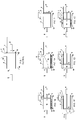
- the apparatus comprises: a cylindrical tubular filtration chamber (3) where the material to be dewatered is processed, comprising an end for feeding the material to be processed and another end for the discharge of the processed material; a filtration surface (4) arranged along the entire useful area of the filtration chamber; a feeding hopper (1) for stocking and feeding the material to be processed, coupled to the filtration chamber through a feed inlet duct (2), through which the material is fed to the filtration chamber next to the feed end of the filtration chamber; a compression plate (5), driven by a driving device (6), for the mechanical compaction of the material, the compression plate having a cross-sectional size slightly smaller than the internal dimensions of the filtration chamber, wherein the compression plate is installed internally and centrally to the filtration chamber, with its longitudinal axis coinciding with the longitudinal axis of the filtration chamber, wherein the compression plate may move along its longitudinal axis from the feed end of the compression chamber - maximum backward position, to the discharge end of the filtration chamber - maximum forward position
- Figure 1A shows the Feeding Stage, with the material (10) that was stored in the hopper (1) feeding, by gravity, the filtration chamber (3), while the compression plate (5) is maintained in its full backward position and the closing plate (8) is maintained fully advanced, closing the exit of the filtration chamber.
- the material (10) is stored in the hopper (1) feeding, by gravity, the filtration chamber (3), while the compression plate (5) is maintained in its full backward position and the closing plate (8) is maintained fully advanced, closing the exit of the filtration chamber.
- the material (10) that was stored in the hopper (1) feeding, by gravity, the filtration chamber (3), while the compression plate (5) is maintained in its full backward position and the closing plate (8) is maintained fully advanced, closing the exit of the filtration chamber.
- the step of Mechanical Compaction of the material (10) begins, with the advancement of the compression plate (5) and the complete closing of the passage of the feed inlet duct (2) to the filtration chamber (3) by the knife gate (7). During this stage, the filtration is carried out under pressure along the entire area of the filtration surface (4), while the material (11) to be processed in the next compaction cycle accumulates in the hopper (1).
- the filtration pressure must be varied along the cycle of operation.
- the forward and backward displacements of the compression plate, as well as the acting force and the associated pressure exerted by the compression plate on the material being processed must be properly controlled throughout the operation and programmed according to a pre-defined "compression pressure x application time" curve, according to the characteristics of each material to be processed.
- control can be automated and programmed, for example, through the installation of electric control valves for the control of the flow and pressure in the circuit of the hydraulic oil, with the operation being controlled by programmed electronic timers according to a pre-defined "pressure x time" curve, according to the characteristics of each material to be processed.
- control can be automated and programmed, for example, by means of electrical-electronic devices for the control of the torque and the variation of the speed of displacement of the compression plate.
- the present invention comprises many innovations that were incorporated io the original concept of the Compaction Press with Piston, which, combined, gave origin to a new equipment for the filtration of sludges, wastes, pasty materials, and suspensions, with many advantages as compared to the previously available techniques.
- the equipment can be designed and programmed to interrupt its operation during the feeding stage, waiting until the complete filling of the filtration chamber (3) with the material to be processed, for only then resuming the operating cycle. This can be done through the installation of a level sensor/controller in the feed inlet duct (2), which, when the filtration chamber is full and the level of sludge reaches the sensor, automatically resumes the operation of the equipment. In such way, the operation is automatically adjusted to meet the demand of flow, even if this flow is not continuous, as in most cases, with frequent interruptions or reductions in the flow of the material to be processed.
- the present invention is characterized, among other things, by the following facts:
- the equipment allows for the easy addition of a washing system for the filtration surface (4), through the installation of water sprays that can be placed externally to the filtration surface (4) and that can be activated after the ejection of the cake and prior to the restart of the feed of the material (11) to the filtration chamber (3), when it is empty of material; complementarily, or instead of that, such water sprays can be placed inside the filtration chamber (3), positioned next to the inner perimeter of the filtration chamber (3), attached to the backward face of (behind) the compression plate (5), moving together with the compression plate while it moves along the filtration chamber (3), cleaning the filtration surface from the inside to the outside, without this cleaning water coming into any contact with the material that is being processed, which could damage its dewatering.
- the present invention is characterized, among other things, by the fact that the ejection of the compacted cake from the filtration chamber (3) is carried out by the advancement of the compression plate (5), promoting the mechanical cleaning of the filtration surface (4), which can also be cleaned by means of water sprays.
- this natural filtrating pre-coat layer exhibits a porosity of very small granulometry, similar in size to the solids in the material that is being dewatered, it is capable of retaining the finest particles in the sludge, thus avoiding the leakage of solid materials during the beginning of the pressurization (sludge leakage), even while the material is still substantially liquid or diluted.
- the aforementioned pre-coat arises promptly, even when the used filtration surface (4) has openings (orifice sizes) that are several times larger than the granulometry of the solids in the material that is being dewatered, as long as the initial filtration pressure being applied on the material during the formation of said pre-coat is low enough and is increased only slowly and gradually.
- the natural filtrating pre-coat starts forming, at first, in a very tenuous way; as this pre-coat is reinforced, the pressure can be gradually increased, observing that it does not exceed the maximum limiting pressure above which the pre-coat can be broken. After a certain point, the natural filtrating pre-coat that is formed acquires enough resistance to support the maximum desired pressure. From this moment onwards, the maximum pressure may be kept fixed, while the cake proceeds its drying.
- the natural filtrating pre-coat is formed by the spontaneous creation of arch-shaped support bridges, such as the ones used in the construction of the ancient stone bridges of the Roman empire, wherein large openings or gaps were overcome by means of the successive support of various smaller pieces of stone.
- the present invention is characterized, among other things, by the fact that, during the initial process of filtration, wherein the material is still very liquid (diluted), it is possible to form a resistant natural filtrating pre-coat on top of the filtration surface (4) and over the mechanical gaps and clearances in the filtration chamber (3), this pre-coat being comprised by the same solid materials contained in the material that is being filtered, even in cases wherein the size of the openings in the filtration surface and of the gaps are much larger than the size of solids in the material that is being filtered, this natural filtrating pre-coat being an extremely efficient way for obtaining a good quality filtrated stream with low amounts of solids in it.
- the cake acts as a sponge, sucking external air through the filtration surface (4) in a direction opposite to the filtration of the liquid (from the outside to the inside), thus forcing a detachment and the breaking of the solids layer next to the filtration surface (4) (the natural filtrating pre-coat) which, due to its excessive compaction, was the main cause for the reduction in the filtration rate.
- the natural filtrating pre-coat which, due to its excessive compaction, was the main cause for the reduction in the filtration rate. It is important to point out that this operation is made when the cake is already with a good consistency of solids, especially alongside the filtration surface, and then the desired effect is much more significant than if the cake were still liquid. Also, as at this moment the cake is well dried alongside the filtration surface (4), it is not necessary to form a new natural filtrating pre-coat, and the filtration may be resumed immediately and at the maximum pressure, with no risks of sludge leaking.
- the present invention is characterized, among other things, by the fact that part of the filtration rate lost with the reduction of permeability of the material that is been processed, which naturally occurs during the process of filtration, can be recovered through a quick procedure of decompression of the compacted material with its subsequent recompression.
- the excellent final dewatering result is due to the perfect complementarity that occurs between the job of expelling the interstitial liquid by the injection of air under pressure and the job of mechanical compaction, which is an exclusive feature of the present invention.
- the injection of air can be carried before the beginning of the step of mechanical compaction, during this stage, or after its completion, depending on the type of material that is being dewatered.
- the injection of air before the mechanical compaction removes the superficial liquid fraction that segregates from the solid fraction during the feeding stage, and also eliminates a large fraction of the interstitial liquid, drastically reducing both the effort and the operating time of the mechanical compression stage.
- the present invention is characterized, among other things, by the fact that the residual humidity of the cake due to the interstitial liquid that is present at the end of the process of filtration and compaction can be reduced by means of a procedure of injection of air into the compacted material, that can be carried out before, during and/or after the step of mechanical compaction of the material.
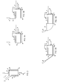
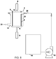
- the filtration chamber (3) is positioned with its longitudinal axis in the horizontal position, however in another preferred embodiment of the present invention, as shown in Figure 2 , the filtration chamber (3) is positioned with its longitudinal axis in the vertical position, keeping the principles, essential characteristics and operating methods described previously.
- the closing device of the filtration chamber (3) is of the knife gate type, wherein the closing plate (8) is installed externally and, in the closing position, is centralized with respect to the filtration chamber, with its longitudinal axis coinciding with the longitudinal axis of the filtration chamber ( Figure 3A ), wherein the closing plate can move perpendicularly to the axis of the filtration chamber, completely closing the discharge end of the filtration chamber in the position of maximum advancement and completely opening the discharge end of the filtration chamber in the position of maximum retreat ( Figure 3B ), so as to allow for the discharge of the processed material.
- This closing system of the filtration chamber can also be used with the option of the filtration chamber positioned with its longitudinal axis in the vertical position, keeping the principles, essential characteristics and operating methods described previously.
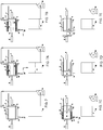
- the closing device of the filtration chamber (3) is of the rotary type, wherein the closing plate (8) is installed externally and, in the closing position, is centralized with respect to the filtration chamber, with its longitudinal axis coinciding with the longitudinal axis of the filtration chamber ( Figure 4A ), wherein the closing plate can rotate around an axis that is perpendicular to the chamber and parallel to the face of the closing plate, so as to displace from the face of the discharge end of the filtration chamber - closed position, to an inclination that allows for the discharge of the processed material - open position ( Figure 4B ).
- This closing system of the filtration chamber can also be used with the option of the filtration chamber positioned with its longitudinal axis in the vertical position, keeping the principles, essential characteristics and operating methods described previously.
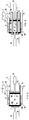
- the filtration is accomplished also or only through filtration surfaces located at the ends (15), installed on the faces of the compression (5) and closing (8) plates, wherein the filtered stream is collected in collectors (16) that are attached to the respective compression and closing plates.
- the installation of the filtration surfaces in the ends (15) can be made in complementation to the filtration surface (4) installed along the filtration chamber (3), to increase the total area available for filtration, keeping the principles, essential characteristics and operating methods described previously.
- the filtration is accomplished also or only through internal filtration surfaces (17), installed inside the filtration chamber (3), wherein the face of the compression plate (5) has openings, fitted with seals with the internal filtration surfaces (17), that allow for the compression plate to pass through these internal filtration surfaces.
- the liquid that is filtered through the internal filtration surfaces (17) flows through orifices in the closing plate (8), being collected in the collector (16) that is attached to the closing plate.
- the installation of the internal filtration surfaces (17) can be made in complementation to the filtration surface (4) installed along the filtration chamber (3) and/or the filtration surfaces in the ends (15), to increase the total area available for filtration, keeping the principles, essential characteristics and operating methods described previously.
- an initial step of dewatering by feeding the sludge (11) to the filtration chamber (3) by pumping the sludge under pressure is added.
- the sludge is being fed under pressure to the filtration chamber, it is already being filtered through the filtration surface (4), concentrating the solids inside the filtration chamber, at the same time that a natural filtrating pre-coat layer of solids is being formed on top of the filtration surfaces, which will serve as sealing and filtration aid for the subsequent step of mechanical compaction.
- the present invention is characterized, among other things, by enabling the association of the advantages of two processes, that of filtration by pumping and that of mechanical compaction, in a single equipment and in an extremely simple way, which is a unique and exceptional characteristic of the present invention.
- the material can be fed to the filtration chamber (3) through a pump (19), with the filtration chamber installed with its longitudinal axis in the vertical position.
- the solid material tends to deposit on the bottom of the filtration chamber, on top of the closing plate (8), while the liquid is filtered through the filtration surface (4), thus facilitating the initial dewatering step by pumping.
- filtration surface can be more appropriate to the operation, including, among others, perforated sheets, trapezoidal bar screens, sintered plates, filtration fabrics structured with metallic screens, porous membranes, sintered meshes laminated in multiple layers, etc., wherein, for each type of filtration surface, there also can be used different openings, porosities or materials of construction.
Applications Claiming Priority (1)
| Application Number | Priority Date | Filing Date | Title |
|---|---|---|---|
| BR102019026860-3A BR102019026860A2 (pt) | 2019-12-16 | 2019-12-16 | Equipamento e método para o desaguamento e compactação de lodos, rejeitos, materiais pastosos e suspensões |
Publications (1)
| Publication Number | Publication Date |
|---|---|
| EP3838851A1 true EP3838851A1 (de) | 2021-06-23 |
Family
ID=73854709
Family Applications (1)
| Application Number | Title | Priority Date | Filing Date |
|---|---|---|---|
| EP20214401.0A Pending EP3838851A1 (de) | 2019-12-16 | 2020-12-16 | Vorrichtung und verfahren zum entwässern und verdichten von schlamm, abfällen, pastösen materialien und flüssigen suspensionen |
Country Status (2)
| Country | Link |
|---|---|
| EP (1) | EP3838851A1 (de) |
| BR (1) | BR102019026860A2 (de) |
Cited By (5)
| Publication number | Priority date | Publication date | Assignee | Title |
|---|---|---|---|---|
| CN113461295A (zh) * | 2021-07-31 | 2021-10-01 | 浙江华硕科技股份有限公司 | 一种胶水的生产水处理工艺用设备及其使用方法 |
| CN114163092A (zh) * | 2021-12-08 | 2022-03-11 | 深圳大学 | 污泥脱水系统及污泥脱水方法 |
| CN114193815A (zh) * | 2021-12-01 | 2022-03-18 | 山东美果来食品有限公司 | 一种用于石榴籽的活性成分提取设备及提取工艺 |
| CN114474819A (zh) * | 2022-01-12 | 2022-05-13 | 中国矿业大学 | 一种真空力与压力连续施加的煤气化细渣快速脱水、型块脱模装置及方法 |
| CN116606050A (zh) * | 2023-06-19 | 2023-08-18 | 广东新泰隆环保集团有限公司 | 一种污泥无害化及资源化的综合处理系统 |
Citations (32)
| Publication number | Priority date | Publication date | Assignee | Title |
|---|---|---|---|---|
| US3347383A (en) | 1965-11-19 | 1967-10-17 | Shriver & Company Inc T | Filter press |
| US3540586A (en) | 1968-05-09 | 1970-11-17 | Holliday Co Ltd L B | Filtration apparatus and method |
| US3601039A (en) | 1968-11-04 | 1971-08-24 | Gen Am Transport | Sludge-dewatering apparatus |
| US3919088A (en) | 1974-03-22 | 1975-11-11 | Alar Eng Corp | Rotary vacuum filter |
| US4202773A (en) | 1977-04-27 | 1980-05-13 | Krauss-Maffei Aktiengesellschaft | Apparatus for the dewatering of sludge |
| US4214519A (en) | 1979-02-01 | 1980-07-29 | Stollenwerk Hubert C | Horizontal fruit press and process for pressing fruit |
| US4276168A (en) | 1978-02-15 | 1981-06-30 | Alb. Klein Gmbh & Co. Kg | Device for dewatering sludge |
| US4335846A (en) | 1981-01-15 | 1982-06-22 | Pennwalt Corporation | Three-phase decanter |
| US4347137A (en) | 1981-06-17 | 1982-08-31 | Norwood Minerals, Inc. | Apparatus for consolidation of slurries of solid particulate materials |
| US4364827A (en) | 1977-07-13 | 1982-12-21 | Envirotech Corporation | Hydraulic filter plate shifter |
| US4420402A (en) | 1981-12-07 | 1983-12-13 | Albany International Corp. | Method and apparatus with couch press for dewatering a slurry of fine particles |
| US4459907A (en) | 1981-09-16 | 1984-07-17 | A. Ahlstrom Osakeyhtio | Press for removing water |
| US4729830A (en) | 1985-12-27 | 1988-03-08 | Kotobuki Iron Works, Ltd. | Three-phase separation device using doubly-canted decanter |
| US4844799A (en) | 1986-07-17 | 1989-07-04 | Lee Chung Y | Filtration apparatus having spaced-apart driving members for changing a size of a treatment zone |
| WO1991008035A1 (de) | 1989-12-01 | 1991-06-13 | Horst Guggemos | Einrichtung zum entwässern von schlämmen |
| US5051194A (en) | 1989-05-10 | 1991-09-24 | Baehr Albert | Procedure and chamber filter press for dewatering slurries and similar substances |
| US5207907A (en) | 1991-03-13 | 1993-05-04 | Degremont | Compact apparatus for treating sludge by draining and pressing |
| US5357855A (en) | 1991-09-24 | 1994-10-25 | Ishigaki Mechanical Industry Co., Ltd. | Screw press for dewatering a slurry |
| US5390592A (en) | 1992-04-11 | 1995-02-21 | Sulzer Escher Wyss Gmbh | Dewatering press for compressibly dewaterable material |
| US5855778A (en) | 1997-08-07 | 1999-01-05 | William R. Perrin Ontario Ltd. | Filter press |
| US5961827A (en) | 1996-08-28 | 1999-10-05 | Baehr; Albert | Apparatus for dewatering of sludge and similar substances |
| US6267889B1 (en) | 2000-01-26 | 2001-07-31 | Mdf, Llc | Rotary drum filter |
| US6387282B1 (en) | 1998-08-26 | 2002-05-14 | Lenser Filtration Gmbh & Co. | Method of drying a filter cake and a press for carrying out the method |
| US6432299B1 (en) | 2000-07-21 | 2002-08-13 | Hutchison-Hayes International, Inc. | Cuttings dryer for removing liquid from a slurry |
| US20030228966A1 (en) | 2000-08-31 | 2003-12-11 | Koch Richard James | Centrifuge systems and methods |
| EP0958023B1 (de) | 1996-10-07 | 2004-09-08 | Spirac Engineering AB | Siebvorrichtung |
| WO2008011796A1 (fr) | 2006-07-21 | 2008-01-31 | Anji Microelectronics (Shanghai) Co., Ltd | Suspension épaisse de polissage pour matériau à faible constante diélectrique |
| US20090090256A1 (en) * | 2007-10-03 | 2009-04-09 | Mealey Jr Robert Edward | Sludge Dewatering System |
| US8137568B2 (en) | 2005-09-26 | 2012-03-20 | Andritz Ltd. | Rotary drum vacuum filter |
| ES2420580T3 (es) | 2003-10-15 | 2013-08-26 | Nordic Water Products Ab | Aparato y método para tratar lodos |
| US8596195B2 (en) | 2010-02-22 | 2013-12-03 | Ark Co. Ltd. | Sludge dehydrating apparatus |
| KR101935428B1 (ko) * | 2018-04-27 | 2019-04-05 | 이진용 | 실린더 가압식 협잡물 탈수장치 |
-
2019
- 2019-12-16 BR BR102019026860-3A patent/BR102019026860A2/pt unknown
-
2020
- 2020-12-16 EP EP20214401.0A patent/EP3838851A1/de active Pending
Patent Citations (32)
| Publication number | Priority date | Publication date | Assignee | Title |
|---|---|---|---|---|
| US3347383A (en) | 1965-11-19 | 1967-10-17 | Shriver & Company Inc T | Filter press |
| US3540586A (en) | 1968-05-09 | 1970-11-17 | Holliday Co Ltd L B | Filtration apparatus and method |
| US3601039A (en) | 1968-11-04 | 1971-08-24 | Gen Am Transport | Sludge-dewatering apparatus |
| US3919088A (en) | 1974-03-22 | 1975-11-11 | Alar Eng Corp | Rotary vacuum filter |
| US4202773A (en) | 1977-04-27 | 1980-05-13 | Krauss-Maffei Aktiengesellschaft | Apparatus for the dewatering of sludge |
| US4364827A (en) | 1977-07-13 | 1982-12-21 | Envirotech Corporation | Hydraulic filter plate shifter |
| US4276168A (en) | 1978-02-15 | 1981-06-30 | Alb. Klein Gmbh & Co. Kg | Device for dewatering sludge |
| US4214519A (en) | 1979-02-01 | 1980-07-29 | Stollenwerk Hubert C | Horizontal fruit press and process for pressing fruit |
| US4335846A (en) | 1981-01-15 | 1982-06-22 | Pennwalt Corporation | Three-phase decanter |
| US4347137A (en) | 1981-06-17 | 1982-08-31 | Norwood Minerals, Inc. | Apparatus for consolidation of slurries of solid particulate materials |
| US4459907A (en) | 1981-09-16 | 1984-07-17 | A. Ahlstrom Osakeyhtio | Press for removing water |
| US4420402A (en) | 1981-12-07 | 1983-12-13 | Albany International Corp. | Method and apparatus with couch press for dewatering a slurry of fine particles |
| US4729830A (en) | 1985-12-27 | 1988-03-08 | Kotobuki Iron Works, Ltd. | Three-phase separation device using doubly-canted decanter |
| US4844799A (en) | 1986-07-17 | 1989-07-04 | Lee Chung Y | Filtration apparatus having spaced-apart driving members for changing a size of a treatment zone |
| US5051194A (en) | 1989-05-10 | 1991-09-24 | Baehr Albert | Procedure and chamber filter press for dewatering slurries and similar substances |
| WO1991008035A1 (de) | 1989-12-01 | 1991-06-13 | Horst Guggemos | Einrichtung zum entwässern von schlämmen |
| US5207907A (en) | 1991-03-13 | 1993-05-04 | Degremont | Compact apparatus for treating sludge by draining and pressing |
| US5357855A (en) | 1991-09-24 | 1994-10-25 | Ishigaki Mechanical Industry Co., Ltd. | Screw press for dewatering a slurry |
| US5390592A (en) | 1992-04-11 | 1995-02-21 | Sulzer Escher Wyss Gmbh | Dewatering press for compressibly dewaterable material |
| US5961827A (en) | 1996-08-28 | 1999-10-05 | Baehr; Albert | Apparatus for dewatering of sludge and similar substances |
| EP0958023B1 (de) | 1996-10-07 | 2004-09-08 | Spirac Engineering AB | Siebvorrichtung |
| US5855778A (en) | 1997-08-07 | 1999-01-05 | William R. Perrin Ontario Ltd. | Filter press |
| US6387282B1 (en) | 1998-08-26 | 2002-05-14 | Lenser Filtration Gmbh & Co. | Method of drying a filter cake and a press for carrying out the method |
| US6267889B1 (en) | 2000-01-26 | 2001-07-31 | Mdf, Llc | Rotary drum filter |
| US6432299B1 (en) | 2000-07-21 | 2002-08-13 | Hutchison-Hayes International, Inc. | Cuttings dryer for removing liquid from a slurry |
| US20030228966A1 (en) | 2000-08-31 | 2003-12-11 | Koch Richard James | Centrifuge systems and methods |
| ES2420580T3 (es) | 2003-10-15 | 2013-08-26 | Nordic Water Products Ab | Aparato y método para tratar lodos |
| US8137568B2 (en) | 2005-09-26 | 2012-03-20 | Andritz Ltd. | Rotary drum vacuum filter |
| WO2008011796A1 (fr) | 2006-07-21 | 2008-01-31 | Anji Microelectronics (Shanghai) Co., Ltd | Suspension épaisse de polissage pour matériau à faible constante diélectrique |
| US20090090256A1 (en) * | 2007-10-03 | 2009-04-09 | Mealey Jr Robert Edward | Sludge Dewatering System |
| US8596195B2 (en) | 2010-02-22 | 2013-12-03 | Ark Co. Ltd. | Sludge dehydrating apparatus |
| KR101935428B1 (ko) * | 2018-04-27 | 2019-04-05 | 이진용 | 실린더 가압식 협잡물 탈수장치 |
Cited By (8)
| Publication number | Priority date | Publication date | Assignee | Title |
|---|---|---|---|---|
| CN113461295A (zh) * | 2021-07-31 | 2021-10-01 | 浙江华硕科技股份有限公司 | 一种胶水的生产水处理工艺用设备及其使用方法 |
| CN114193815A (zh) * | 2021-12-01 | 2022-03-18 | 山东美果来食品有限公司 | 一种用于石榴籽的活性成分提取设备及提取工艺 |
| CN114193815B (zh) * | 2021-12-01 | 2023-12-15 | 山东美果来食品有限公司 | 一种用于石榴籽的活性成分提取设备及提取工艺 |
| CN114163092A (zh) * | 2021-12-08 | 2022-03-11 | 深圳大学 | 污泥脱水系统及污泥脱水方法 |
| CN114474819A (zh) * | 2022-01-12 | 2022-05-13 | 中国矿业大学 | 一种真空力与压力连续施加的煤气化细渣快速脱水、型块脱模装置及方法 |
| CN114474819B (zh) * | 2022-01-12 | 2023-07-25 | 中国矿业大学 | 一种煤气化细渣快速脱水、型块脱模装置及方法 |
| CN116606050A (zh) * | 2023-06-19 | 2023-08-18 | 广东新泰隆环保集团有限公司 | 一种污泥无害化及资源化的综合处理系统 |
| CN116606050B (zh) * | 2023-06-19 | 2023-12-22 | 广东新泰隆环保集团有限公司 | 一种污泥无害化及资源化的综合处理系统 |
Also Published As
| Publication number | Publication date |
|---|---|
| BR102019026860A2 (pt) | 2021-06-22 |
Similar Documents
| Publication | Publication Date | Title |
|---|---|---|
| EP3838851A1 (de) | Vorrichtung und verfahren zum entwässern und verdichten von schlamm, abfällen, pastösen materialien und flüssigen suspensionen | |
| KR100481628B1 (ko) | 회전식 압축 여과기 | |
| KR101255321B1 (ko) | 여과장치 및 여과방법 | |
| KR101495906B1 (ko) | 협잡물 탈수성능을 향상시킨 협잡물 처리기 | |
| JPH0357595A (ja) | 連続濾過装置 | |
| EP2106834A1 (de) | Vorrichtung zur Abwasserfiltrierung | |
| CN203842373U (zh) | 加压连续固液分离净化装置 | |
| JP3903069B1 (ja) | 回転加圧脱水機および回転加圧脱水機による汚泥の脱水方法 | |
| KR102379522B1 (ko) | 협잡물 분리 성능이 향상된 협잡물 종합처리장치 | |
| CN219239492U (zh) | 一种自吸式压滤脱水设备及固液分离器 | |
| BR102018017347A2 (pt) | Equipamento e método para o desaguamento e compactação de lodos, rejeitos, materiais pastosos e suspensões | |
| CN115259615A (zh) | 一种泥浆筛分脱水用卧螺式沉降离心脱水机 | |
| KR100678990B1 (ko) | 필터프레스식 탈수장치 | |
| JP4247840B2 (ja) | 汚泥脱水ユニット、及びそれを用いた汚泥吸引脱水装置 | |
| KR101495905B1 (ko) | 모래여과의 안정성이 향상된 협잡물 처리기 | |
| CN206970440U (zh) | 污泥深度脱水装置 | |
| CN108325258A (zh) | 多功能固液分离机及其反冲洗方法 | |
| JPH09271612A (ja) | 固液分離装置 | |
| CN215828610U (zh) | 一种离心粪污分离机 | |
| CN212188119U (zh) | 一种混合污水固液分离装置 | |
| DE202004015115U1 (de) | Vorrichtung zum Abscheiden und Entwässern von Grobstoffen | |
| CN104275246A (zh) | 一种沉降过滤离心机及其方法 | |
| CN109464838A (zh) | 多功能带自动刮刀系统的陶瓷过滤机 | |
| CN218025812U (zh) | 一种污泥离心脱水装置 | |
| CN212308996U (zh) | 一种新型机械挤压式压滤机 |
Legal Events
| Date | Code | Title | Description |
|---|---|---|---|
| PUAI | Public reference made under article 153(3) epc to a published international application that has entered the european phase |
Free format text: ORIGINAL CODE: 0009012 |
|
| STAA | Information on the status of an ep patent application or granted ep patent |
Free format text: STATUS: THE APPLICATION HAS BEEN PUBLISHED |
|
| AK | Designated contracting states |
Kind code of ref document: A1 Designated state(s): AL AT BE BG CH CY CZ DE DK EE ES FI FR GB GR HR HU IE IS IT LI LT LU LV MC MK MT NL NO PL PT RO RS SE SI SK SM TR |
|
| STAA | Information on the status of an ep patent application or granted ep patent |
Free format text: STATUS: REQUEST FOR EXAMINATION WAS MADE |
|
| 17P | Request for examination filed |
Effective date: 20211217 |
|
| RBV | Designated contracting states (corrected) |
Designated state(s): AL AT BE BG CH CY CZ DE DK EE ES FI FR GB GR HR HU IE IS IT LI LT LU LV MC MK MT NL NO PL PT RO RS SE SI SK SM TR |
|
| STAA | Information on the status of an ep patent application or granted ep patent |
Free format text: STATUS: EXAMINATION IS IN PROGRESS |
|
| 17Q | First examination report despatched |
Effective date: 20220224 |