EP3837924B1 - Microwave sensor device, and sensing methods, and lighting system using the sensor device - Google Patents
Microwave sensor device, and sensing methods, and lighting system using the sensor device Download PDFInfo
- Publication number
- EP3837924B1 EP3837924B1 EP19744735.2A EP19744735A EP3837924B1 EP 3837924 B1 EP3837924 B1 EP 3837924B1 EP 19744735 A EP19744735 A EP 19744735A EP 3837924 B1 EP3837924 B1 EP 3837924B1
- Authority
- EP
- European Patent Office
- Prior art keywords
- microwave
- signal
- sensor device
- transmit
- frequency
- Prior art date
- Legal status (The legal status is an assumption and is not a legal conclusion. Google has not performed a legal analysis and makes no representation as to the accuracy of the status listed.)
- Active
Links
Images


Classifications
-
- G—PHYSICS
- G01—MEASURING; TESTING
- G01S—RADIO DIRECTION-FINDING; RADIO NAVIGATION; DETERMINING DISTANCE OR VELOCITY BY USE OF RADIO WAVES; LOCATING OR PRESENCE-DETECTING BY USE OF THE REFLECTION OR RERADIATION OF RADIO WAVES; ANALOGOUS ARRANGEMENTS USING OTHER WAVES
- G01S13/00—Systems using the reflection or reradiation of radio waves, e.g. radar systems; Analogous systems using reflection or reradiation of waves whose nature or wavelength is irrelevant or unspecified
- G01S13/02—Systems using reflection of radio waves, e.g. primary radar systems; Analogous systems
- G01S13/50—Systems of measurement based on relative movement of target
- G01S13/52—Discriminating between fixed and moving objects or between objects moving at different speeds
- G01S13/56—Discriminating between fixed and moving objects or between objects moving at different speeds for presence detection
-
- G—PHYSICS
- G01—MEASURING; TESTING
- G01S—RADIO DIRECTION-FINDING; RADIO NAVIGATION; DETERMINING DISTANCE OR VELOCITY BY USE OF RADIO WAVES; LOCATING OR PRESENCE-DETECTING BY USE OF THE REFLECTION OR RERADIATION OF RADIO WAVES; ANALOGOUS ARRANGEMENTS USING OTHER WAVES
- G01S13/00—Systems using the reflection or reradiation of radio waves, e.g. radar systems; Analogous systems using reflection or reradiation of waves whose nature or wavelength is irrelevant or unspecified
- G01S13/87—Combinations of radar systems, e.g. primary radar and secondary radar
-
- G—PHYSICS
- G01—MEASURING; TESTING
- G01S—RADIO DIRECTION-FINDING; RADIO NAVIGATION; DETERMINING DISTANCE OR VELOCITY BY USE OF RADIO WAVES; LOCATING OR PRESENCE-DETECTING BY USE OF THE REFLECTION OR RERADIATION OF RADIO WAVES; ANALOGOUS ARRANGEMENTS USING OTHER WAVES
- G01S13/00—Systems using the reflection or reradiation of radio waves, e.g. radar systems; Analogous systems using reflection or reradiation of waves whose nature or wavelength is irrelevant or unspecified
- G01S13/88—Radar or analogous systems specially adapted for specific applications
-
- Y—GENERAL TAGGING OF NEW TECHNOLOGICAL DEVELOPMENTS; GENERAL TAGGING OF CROSS-SECTIONAL TECHNOLOGIES SPANNING OVER SEVERAL SECTIONS OF THE IPC; TECHNICAL SUBJECTS COVERED BY FORMER USPC CROSS-REFERENCE ART COLLECTIONS [XRACs] AND DIGESTS
- Y02—TECHNOLOGIES OR APPLICATIONS FOR MITIGATION OR ADAPTATION AGAINST CLIMATE CHANGE
- Y02B—CLIMATE CHANGE MITIGATION TECHNOLOGIES RELATED TO BUILDINGS, e.g. HOUSING, HOUSE APPLIANCES OR RELATED END-USER APPLICATIONS
- Y02B20/00—Energy efficient lighting technologies, e.g. halogen lamps or gas discharge lamps
- Y02B20/40—Control techniques providing energy savings, e.g. smart controller or presence detection
Definitions
- This invention relates to microwave sensor devices, for example for presence and movement detection. Such detection may then be used to control other devices, such as luminaires of a lighting system.
- Lighting devices are well known with infrared PIR sensors for motion, and hence presence, detection.
- An alternative which is becoming increasingly popular is the use of a microwave sensor. This type of sensor may be more sensitive and it is also able to function through a lighting device lens, thus enabling more compact integration of the sensor into a lighting device.
- a simple smart road lighting system requires basic interaction between the lighting devices.
- a target object such as a car or pedestrian
- an extra RF communications system is required to realize this basic communication function. This increases the system cost and complexity.
- WO2014/033618A1 it has been proposed to make reuse of the presence detector to implement the communication between devices.
- One example is disclosed in WO2014/033618A1 , in which presence detectors are integrated with lighting devices.
- the presence detector uses a first signal frequency for activity detection, and uses a second sweeping frequency with respect to its frequency for signal for communication.
- the presence detector however requires two monitoring units; one for activity detection and one for communication reception.
- the solution provides a simplification of the hardware required but there is still a need for a more simple implementation.
- EP2214032A1 dislcoses an apparatus according to the preamble of claim 1.
- activity e.g. motion or presence
- signal communication sending and/or receiving
- a first microwave sensor device for detecting activity and for sending a communications signal to a second microwave sensor device, comprising:
- This sensor device detects an activity such as motion and also generates a communications signal using the same transceiver.
- the communications signal is designed to be detected by the second sensor device in the same way as for motion detection at that second sensor device.
- the second characteristics may for example be thought of as identifying an artificial activity signal (whereas the first and second sensor devices are preferably positionally fixed relative to each other).
- This artificial activity signal has a characteristic difference with respect to the transmit signal of the second sensor device.
- the artificial activity signal for example has a frequency shift with respect to the microwave transmit signal of the second sensor.
- This means the reception of the communications signal at the second sensor device also takes place with the same transceiver, since it is detected in the same way as a activity signal since the characteristic difference is inherently identifiable by the second sensor device.
- the overall hardware required to implement communication is simplified.
- the control unit is adapted to transmit the microwave communications signal in response to the detection of movement as the activity, and said communications signals is adapted to mimic the microwave transmit signal of the second microwave sensor device reflected by a moving object, by having the second characteristic difference equal to the characteristic variation of the characteristic of the microwave transmit signal of the second microwave sensor device caused by the moving object.
- the communications signal is for example used to alert adjacent sensor units to the presence of an approaching moving object, so that action may be taken in advance, such as providing lighting in an area approached by the moving object.
- the second characteristic difference is outside the range of the characteristic variation of the characteristic of the microwave transmit signal of the second microwave sensor device caused by the moving object.
- the first and second characteristic differences may each comprise a frequency difference
- the control unit is adapted to transmit the communications signal with a frequency having a frequency difference with respect to the frequency of the microwave transmit signal of the second microwave sensor device, wherein the second frequency difference is equal to the frequency variation of the frequency of the microwave transmit signal of the second microwave sensor device caused by the moving object due to Doppler effect.
- Frequency difference is one parameter in common Doppler effect-based detection, thus by providing a communications signal with a frequency difference from the second sensor device, the second sensor device is able to detect this frequency difference and deem it is a motion based on the Doppler effect.
- the first sensor device in another embodiment of the invention can provide a varied signal strength in order to mimic the presence of a new object.
- phase shift of a signal can also be mimicked in case that phase shift is used for detection at the second sensor device.
- phase shift is used for detection at the second sensor device.
- first and the second characteristic difference can be of the same type, for example both may be a frequency difference, or the characteristic differences can be different.
- first characteristic difference may be a frequency difference whereas the second characteristic difference is a phase difference.
- the value/amplitude of the difference can also be the same or different.
- control unit may be adapted to transmit the communications signal with a fixed frequency difference or with a dynamic pattern of frequency difference.
- a fixed frequency difference is simple for the second sensor device to detect.
- a dynamic pattern can embed more information or even a digital communications signal, thus is robust and efficient.
- the control unit is for example adapted to transmit a microwave transmit signal with a first frequency characteristic during a first time period for the detection of activity , and to transmit the communications signal with a second characteristic (e.g. based on a dynamic frequency) during a second time period.
- the sensor device thus operates a time division approach, with the activity detection using a static microwave transmit signal at one time, and with the communication using a microwave transmit signal at another time.
- the transceiver can also be able to send the transmit signal and the communications signal at the same time.
- the sensor device may be further for receiving a communications signal from a third microwave sensor device, wherein the detector is adapted to process the communications signal from the third microwave sensor device and the microwave transmit signal of the first sensor device to thereby to determine activity based on a third characteristic difference between the microwave transmit signal of the first microwave sensor and the communications signal from the third microwave sensor device.
- the first sensor device is thus able to be triggered by communications signals from a third sensor device, besides by a real movement of a real object.
- the reception uses the same transceiver, since the communications signal has the characteristics of a particular activity (e.g. movement) profile.
- the microwave receive signal is a reflected version of the microwave transmit signal in the case of activity detection, whereas it is a microwave communications signal from another sensor device in the case of receiving a communication.
- a second microwave sensor device for detecting activity and for receiving a communications signal from a first microwave sensor device, comprising:
- the second characteristic difference is either the same or different from the first characteristic difference.
- the frequency difference between the transmit microwave signal and the communications signal is equal to the frequency variation of the frequency of the microwave transmit signal of the second microwave sensor device caused by a moving object.
- the communication is interpreted by determining activity hence using the same approach as for activity detection, because the communications signal mimics an activity (e.g. motion) by mimicking the reflected transmit signal of the second sensor device.
- a received communications signal with particular characteristics indicates detection of activity.
- the frequency difference is outside the range of the frequency variation of the frequency of the microwave transmit signal of the second microwave sensor device caused by the moving object.
- the communication does not interfere the original sensing of moving object in the second microwave sensor device.
- the first and the second characteristic differences comprise frequency differences
- the detector is adapted to detect the frequency difference from the transmit microwave signal and the receive microwave signal, and the frequency difference from the transmit microwave signal and the communications signal.
- Frequency difference is usually used in Doppler effect-based motion detection, like microwave/radar sensor.
- a simple mixer may be used to implement homodyne mixing to derive the signal properties, corresponding to the first and second characteristics.
- the second characteristic difference is either a fixed frequency difference or a dynamic pattern of frequency difference.
- the fixed frequency difference is simple for detection.
- the dynamic pattern for example may be a frequency sweep of the microwave receive signal which crosses a static frequency of the microwave transmit signal.
- a frequency sweep creates an identifiable and unique pattern in the frequency difference components.
- the microwave receive signal may have constant amplitude, which further distinguishes over the signals reflected by real moving objects.
- the first sensor may mimic a constant frequency shift and in a second example it may mimic an unnatural frequency shift.
- a conventional second sensor can be used, whereas for the second case the second sensor is adapted to detect the unnatural shift.
- a dynamic pattern of frequency difference may comprise an increasing frequency sweep over time which represents a first communication symbol value and a decreasing frequency sweep over time which represents a second communication symbol value.
- the communications signal may be formed as a word of bits/symbols, where each bit/symbol takes a value which depends on the direction of the frequency sweep.
- information may be encoded in the communications signal as a data stream.
- the detector for example generates orthogonal I and Q intermediate frequency signals.
- the use of two orthogonal components enables the positive and negative frequency sweeps to be distinguished from each other.
- the microwave transceiver (of the second sensor device) may be adapted to transmit a further communications signal to a next microwave sensor device in order to spread the communications signal from the first microwave sensor device, wherein said further communications signal is for detection at the next microwave sensor device to form a third characteristic difference between the further communications signal and a microwave transmit signal of the next microwave sensor device.
- a communications signal is propagated along a series chain of sensor devices.
- the communications signal is propagated until a certain distance of spreading has been reached. This provides a finite distance of activity/motion trigger.
- the invention also provides a first luminaire, comprising:
- This luminaire is able to send information to other luminaires when it detects local activity. In this way, a series of luminaires may be controlled automatically in response to objects moving through different illumination areas.
- the invention also provides a second luminaire, comprising:
- the invention also provides a lighting system comprising:
- the first aspect of the invention also provides a method of detecting activity at a first microwave sensor device and sending a communications signal to a second microwave sensor device, comprising:
- the method may further comprise receiving a communications signal from a third microwave sensor device, wherein the detector is adapted to process the communications signal from the third microwave sensor device and the microwave transmit signal of the first sensor device to thereby to determine activity based on a third characteristic difference between the microwave transmit signal and the communications signal from the third microwave sensor device.
- the second aspect of the invention also provides a method of detecting activity at a second microwave sensor device and receiving a communication from a first microwave sensor device, comprising:
- the invention provides a microwave sensor device for detecting activity and for sending and/or receiving a communications signal to/from a second microwave sensor device.
- a microwave transceiver is used for transmitting a microwave transmit signal and for receiving a microwave receive signal.
- activity detection such as motion detection
- the microwave receive signal is a reflected version of the microwave transmit signal and the signals are processed to identify a first signal characteristic difference.
- the communications signal is for detection at another sensor device.
- the communications signal and a microwave transmit signal of the another sensor device are processed at the another sensor device to identify a second characteristic difference.
- This sensor device detects activity such as motion and also transmits and/or receives a communications signal using the same transceiver.
- the communications signal is designed to be detected by a remote sensor device in the same way as for activity (e.g. motion) detection.
- the basic principle of operation of a microwave sensor is to measure Doppler frequency shifts. Wave fronts transmitted by a microwave generator hit a moving target. Depending on the direction of the motion of this target, the wave fronts are either compressed or expanded, which results in a shift in frequency. The signal, shifted in frequency and reflected, is subtracted from the original unchanged microwave transmit signal in a relatively simple homodyne mixer, to result in a sinusoidal intermediate frequency (IF). This is well known in traditional sensor devices.
- IF sinusoidal intermediate frequency
- the microwave signal sent by one device may be received by an adjacent device.
- the microwave sensor transmit signal for example has a propagation distance of several tens of meters.
- This invention is based on making use of this interference between sensor devices. If the two microwave sensor devices have close enough frequency (e.g. within kHz), the second sensor will receive the signal from first sensor and amplify the intermediate frequency signal (IF) for processing. By setting the signal from the first sensor such that it resembles a reflected signal of the transmit signal of the second sensor, the second sensor would also detect a frequency shift and determines that there is a moving object reflecting this signal, thus a motion will be considered to have been sensed.
- IF intermediate frequency signal
- Figure 1 shows the basic principle of operation of the system of the invention, used as part of a road lighting system by way of example. Note that other applications like indoor lighting are also possible.
- the road lighting system 10 comprises a series of luminaires, of which two, 20 and 30, are shown.
- a first luminaire 20 has a first microwave sensor device 22 for detecting motion and for sending a communications signal to a second microwave sensor device 32 at the second luminaire 30.
- the microwave sensor device 22 transmits a microwave transmit signal T1a and receives a microwave receive signal R1 which is a reflection of the microwave transmit signal T1a for example from a moving van 40. Movement is detected based on a first characteristic difference between the microwave transmit signal T1a and the microwave receive signal R1. Preferably the first characteristic difference is frequency difference/shift between the two microwave signals. This is suitable for conventional and well-known Doppler effect-based motion detection. The well-known Doppler detection will not be described further.
- the microwave transceiver of the sensor device 22 is also controlled to transmit a communications signal T1b for detection at the second microwave sensor device 32.
- the second microwave sensor device 32 functions in the same way as the first. Thus, it is used to analyze a difference between its own microwave transmit signal T2a and a receive signal.
- the communications signal T1b instead of being a reflected signal from a moving object, functions as the receive signal R2.
- a second characteristic difference between the communications signal T1b and the microwave transmit signal T2a of the second microwave sensor device is determined. This second characteristic difference encodes a communications signal.
- the first sensor device 22 detects motion and also generates a communications signal using the same transceiver.
- the communications signal T1b is detected by the second sensor device 32 in the same way as for motion detection at that second sensor device.
- the communications signal mimics the microwave transmit signal of the second microwave sensor device T2a after reflection by a moving object. This means that no adaptation of the detection system in the second sensor device 32 is needed.
- the second characteristic difference represents an artificial movement signal.
- the first and second sensor devices are positionally fixed relative to each other for example at street lighting luminaires, so that the movement signal is artificial in that it is not generated by a Doppler shift.
- the second characteristic difference is identifiably either the same or different to the characteristics caused by movement of real objects, such as people or vehicles.
- the artificial movement signal for example has a fixed frequency shift with respect to the microwave transmit signal T2a of the second sensor or else a varying frequency shift. Because of the fixed distance between the two sensor devices, the received amplitude is constant. This constant amplitude as well as a specific (fixed or dynamic) frequency difference, enables the communications signals to be identified even in when there are additionally reflections from moving objects.
- the microwave communications signal T1b may be transmitted in response to the detection of movement.
- the communications signal is then used to alert adjacent sensor units to the presence of an approaching moving object 40, so that action may be taken in advance, such as providing lighting in an area approached by the moving object.
- the action may also be something else like doing some preparation in the microwave sensing for the incoming moving object.
- the communication is implemented between the two microwave sensor devices 22 and 32.
- the first and second characteristic differences each comprise a frequency difference, which in turn is representative of a movement in the specific example being described.
- the communications signal T1b is generated with a frequency such that an identifiable frequency difference is present with respect to the frequency of the microwave transmit signal T2a of the second microwave sensor device 32.
- This frequency difference (between T2a and R2) may be fixed or it may have a dynamic pattern.
- the two microwave sensor devices 22, 32 are preferably the same, i.e. each one is able to transmit a communications signal as explained for microwave sensor device 22 and receive a communications signal as explained for microwave sensor device 32.
- all communications signals may be identifiable as different to signals from real moving objects.
- the communications signal may not be identifiably different (for example a fixed frequency).
- the purpose is simply to relay a message that there is a moving object in the vicinity, it does not matter if the signal is from a real moving object or if it a received message that a moving object has been detected at a different location.
- the action to be performed may be the same, namely to alert all other units within a certain area of the activity detection that has taken place.
- FIG. 2 shows an example of the components of the microwave sensor device 22, 32.
- the device comprises a microwave transceiver 50 having a transmitter 52 for transmitting the microwave transmit signal and a receiver 54 for receiving the receive signal which is either a reflection of the microwave transmit signal or a simulated reflection of the microwave transmit signal (i.e. the communications signal T1b).
- a detector 56 processes the microwave transmit signal and the microwave receive signal thereby to detect movement based on the first characteristic difference between the microwave transmit signal and the microwave receive signal.
- the detector 56 comprises a mixer to implement homodyne mixing to derive the signal properties, corresponding to the first and second characteristics.
- a control unit 58 is provided to control the microwave transceiver 50 to transmit the communications signal for detection at the second microwave sensor device, and thereby to form the second characteristic difference as explained above.
- the communication between sensor devices is preferably bidirectional, i.e. each adjacent pair of sensor devices can communicate with each other.
- the moving object (van 40 in Figure 1 ) may be travelling in either direction, so one luminaire will need to communicate with the luminaires on either side depending on the direction of approach.
- a first luminaire and first sensor device may send a signal to a second luminaire and second sensor device.
- the second luminaire and second sensor device thus receive a signal from the first luminaire and first sensor device.
- the first luminaire and first sensor device may send also receive a signal from a third luminaire and third sensor device (which may be the same one as the second luminaire and second sensor device, or it may be a different one).
- FIG. 3 is a simple example to explain how communications signals may be sent and received. It shows a timing diagram for five different luminaires L1 to L5. Each timing diagram shows the output frequency of the sensor. Each luminaire has a period for receiving signals when the output frequency is constant (the flat line) and a period for transmitting a ramp signal (shown in a hatched area). The duration of the receiving time is twice as long as the duration for transmitting. Thus, the receiving occupies two time slots whereas the transmitting occupies one time slot. The time slots are shown separated by dashed lines.
- the vertical arrows show that the transmitted signal (sent during the hatched areas) is received at the two neighboring luminaires during their reception time periods.
- the transmit time periods are staggered so that when one luminaire is in communications signal transmit mode, the two neighboring luminaires are in receive mode.
- a first difference characteristic is determined between a transmitted signal T1a and a reflected received signal R1.
- Communication reception also takes place (if there is a communications signal to receive), i.e. a second difference characteristic is determined between a transmitted signal and a received communications signal (e.g. between T2a and T1b).
- the communications signal (T1b for the first sensor device) is sent out.
- Figure 3 shows that a transmitted signal may be received by the following luminaire or by the preceding luminaire. If the range of the transmit signal is only to the next or preceding luminaire, only one communications signal is ever received in any individual time slot.
- This simple time scheme ensures that a sensor is always ready to receive a transmitted signal from a neighboring sensor.
- one luminaire When one luminaire receives a communications signal, it may transmit a further communications signal to a next luminaire, and hence the next microwave sensor device, in order to spread the communications signal from the first microwave sensor device, preferably until a certain distance of spreading has been reached.
- the further communications signal is for detection at the next microwave sensor device to form a third characteristic difference (which may be the same or different as the second characteristic difference) between the further communications signal and a microwave transmit signal of the next microwave sensor device. In this way, a communications signal is propagated along a series chain of sensor devices.
- Figure 3 is based on a single type of communications signal, but there may be multiple communications signals used within the system.
- different sensor devices may employ different communications signals (leading to different characteristic differences) so that each communications signal also itself identifies the source of the signal. This may for example enable one sensor device to send a signal to multiple other devices at the same time, instead of the more simple adjacent communication system shown in Figure 3 .
- FIG 4 shows an example of the microwave transmit signal T1a (for motion detection) with a constant frequency of 24 GHz.
- the communications signal T1b comprises a frequency sweep from 23GHz to 25GHz.
- the sweep frequency T1b of the first sensor device is to be received by the second sensor device.
- the frequency sweep is sent to the second sensor device, it has its transmit frequency fixed as shown in Figure 3 (the transmit frequency is fixed during times R1 and R2).
- the output relates only to the second characteristic difference, i.e. the difference between the communications signal T1b and the transmit signal T2a.
- the output frequency is high when the difference is high, and is close to 0Hz when the two frequencies are equal (i.e. at the crossing point). Since the amplitude of the communications signal T1b is keep stable and the distance between two devices is also stable, the output signal amplitude of the second sensor device is constant with only the frequency changing.
- the output signal frequency of the second sensor is also -1MHz to 1MHz shown as the bottom plot in Figure 4 .
- This waveform is processed in the same way as for any other movement pattern (such as a man walking or a car driving) by the existing algorithm. It is noted that for the purposes of limiting the processing requirements, and the filter bandwidths, a signal range 60 between -100KHz to +100KHz may be used for signal processing.
- Figure 5 shows some further details of the sensor device.
- the receiving sensor device Based on detecting the difference frequency pattern, the receiving sensor device is able to identify the signal as a communication from an adjacent sensor.
- the receiver 54 generates quadrature intermediate frequency components IF-I and IF-Q, which are passed through band pass amplifiers 70 to the detector 56 which comprises a signal processor 72.
- Part of the signal processor 72 implements the control unit 58 by providing a frequency sweep command to the transceiver 50, via a D/A converter 74 and trimming circuit 76.
- the transmitter 52 comprises a voltage controlled oscillator (VCO) for implementing the frequency sweep.
- VCO voltage controlled oscillator
- the frequency trimming range is large (several MHz/V), so a precise trimming circuit such as a voltage divider and DC shift unit is used to enable accurate frequency trimming within a small range.
- quadrature sensing signals with identical signal output but with a phase shift, means the direction of a moving object can be determined (according to the receive frequency changing direction).
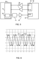
- Figure 6 shows the IF-I and IF-Q signals (versus time) for a constant frequency difference, corresponding to a moving object with constant speed.
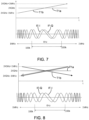
- Figure 7 shows a positive frequency sweep for the communications signal T1b and Figure 8 shows a negative frequency sweep for the communications signal T1b.
- This feature provides two distinguishable states for communication, with different directions of sweep frequency.
- the sensor device receiving the communications signal can identify these two behaviors by the different I and Q channel phase shifts, as can be seen from the bottom plots in Figures 7 and 8 .
- each frequency sweep may encode a single symbol (bit) of data transmission, with several frequency sweep operations enabling a simple data string to be sent out.
- the data transmission rate is determined by the possible frequency sweeping speed.
- the frequency sweep creates an identifiable and unique pattern in the frequency difference components.
- the reception system is then adapted to recognize the particular pattern.
- the sending (first) sensor may instead mimic a constant frequency shift, i.e. representing a specific Doppler shift.
- a completely conventional sensor can may be used to detect this and as long as it represents a response which will not arise from a moving object (e.g. because the speed is too high, or the amplitude is too constant), it can be identified as a communications signal.
- the invention may be employed generally for communication between sensor devices. However, as explained above, the invention is of particular interest for lighting applications which combine microwave presence/movement sensors and basic communication.
- Figure 9 shows a lighting control method.
- a sensor monitoring mode is started in one luminaire.
- step 92 it is determined if a useful sensing signal has been received (i.e. signifying movement or receipt of a communication).
- step 94 the type of received signal is determined. If a movement detection signal is determined, the luminaire lighting unit is turn on in step 96 and a communications signal is sent in step 98 relating to the movement detection and the method returns to step 90.
- a communications signal is determined in step 94, the signal is decoded in step 100, and it is also determined if another message needs to be relayed to a next luminaire (i.e. it is determined if the luminaire is the last one in the series or is the last one which needs to be turned on because it is as the limit of the distance range over which lighting is required). If it is not the last lighting unit to be turned on then the method proceeds to step 96. If it is the last, the lighting unit is turned on in step 102 and the method returns to step 90 (i.e. without the communications step 98).
- the frequency difference is within/equal to the range of Doppler frequency shift due to moving object.
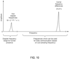
- An alternative embodiment is making the frequency difference between the communication signal of the first device and the transmit signal of the second device outside the range of Doppler frequency shift due to moving object.
- Figure 10 shows the frequency difference for communication is higher than the normal Doppler shift. This embodiment has an advantage of not disturbing the sensing function of the second device, such that the true motion-doppler signal region is also present as the region of interest to the detection algorithm.
Landscapes
- Engineering & Computer Science (AREA)
- Radar, Positioning & Navigation (AREA)
- Remote Sensing (AREA)
- Physics & Mathematics (AREA)
- Computer Networks & Wireless Communication (AREA)
- General Physics & Mathematics (AREA)
- Electromagnetism (AREA)
- Radar Systems Or Details Thereof (AREA)
- Arrangements For Transmission Of Measured Signals (AREA)
- Geophysics And Detection Of Objects (AREA)
- Circuit Arrangement For Electric Light Sources In General (AREA)
Applications Claiming Priority (3)
| Application Number | Priority Date | Filing Date | Title |
|---|---|---|---|
| CN2018100440 | 2018-08-14 | ||
| EP18204390 | 2018-11-05 | ||
| PCT/EP2019/070581 WO2020035314A1 (en) | 2018-08-14 | 2019-07-31 | Microwave sensor device, and sensing methods, and lighting system using the sensor device |
Publications (2)
| Publication Number | Publication Date |
|---|---|
| EP3837924A1 EP3837924A1 (en) | 2021-06-23 |
| EP3837924B1 true EP3837924B1 (en) | 2023-07-19 |
Family
ID=74978862
Family Applications (1)
| Application Number | Title | Priority Date | Filing Date |
|---|---|---|---|
| EP19744735.2A Active EP3837924B1 (en) | 2018-08-14 | 2019-07-31 | Microwave sensor device, and sensing methods, and lighting system using the sensor device |
Country Status (3)
| Country | Link |
|---|---|
| EP (1) | EP3837924B1 (https=) |
| JP (1) | JP7331085B2 (https=) |
| CN (1) | CN112534296B (https=) |
Family Cites Families (26)
| Publication number | Priority date | Publication date | Assignee | Title |
|---|---|---|---|---|
| GB2120491B (en) * | 1982-04-21 | 1985-06-26 | Racal Security Ltd | Improvements in and relating to signal transmitting and receiving arrangements |
| JP2586184B2 (ja) * | 1990-05-28 | 1997-02-26 | 三菱電機株式会社 | マイクロ波回路装置 |
| JPH07301669A (ja) * | 1994-05-06 | 1995-11-14 | Yokogawa Denshi Kiki Kk | Fm−cwレーダの性能検査装置 |
| WO2004074866A1 (ja) * | 2003-02-19 | 2004-09-02 | Hitachi, Ltd. | 物体監視センサ |
| JP2007155551A (ja) * | 2005-12-06 | 2007-06-21 | Toyota Motor Corp | 車載レーダ装置 |
| ES2393459T3 (es) * | 2007-10-11 | 2012-12-21 | Jenoptik Robot Gmbh | Procedimiento para la detección y documentación de infracciones de tráfico en un semáforo |
| EP2214032A1 (en) * | 2009-01-30 | 2010-08-04 | Ford Global Technologies, LLC | A method and system for presence detection |
| JP2011124187A (ja) * | 2009-12-14 | 2011-06-23 | Panasonic Electric Works Co Ltd | 照明システム |
| WO2012023087A1 (en) * | 2010-08-16 | 2012-02-23 | Koninklijke Philips Electronics N.V. | Multiple radar system |
| EP2636283B1 (en) * | 2010-11-02 | 2018-08-29 | Philips Lighting Holding B.V. | Lighting system with radar detection |
| JP2012168048A (ja) * | 2011-02-15 | 2012-09-06 | Panasonic Corp | ドップラーセンサ及び該ドップラーセンサを用いた照明器具 |
| JP2013065452A (ja) * | 2011-09-16 | 2013-04-11 | Agata Denshi Kk | 照明システム |
| WO2013056731A1 (en) * | 2011-10-19 | 2013-04-25 | Telefonaktiebolaget L M Ericsson (Publ) | A motion detector device |
| CN103998951A (zh) * | 2011-11-21 | 2014-08-20 | 大陆-特韦斯贸易合伙股份公司及两合公司 | 借助通信信号实现对象位置确定的方法和装置、以及该装置的使用 |
| EP2891140B1 (en) * | 2012-08-28 | 2020-02-05 | Signify Holding B.V. | Presence detector and method of operating a presence detector |
| DE102012025065A1 (de) * | 2012-12-19 | 2014-06-26 | Valeo Schalter Und Sensoren Gmbh | Verfahren zur Detektion eines Störsignalanteils in einem elektrischen Empfangssignal eines Ultraschallsensors, Ultraschallsensorvorrichtung und Kraftfahrzeug |
| DE102013201836A1 (de) * | 2013-02-05 | 2014-08-07 | Continental Teves Ag & Co. Ohg | Verfahren und Vorrichtung zur Anwesenheitserkennung von Objekten in einer Fahrgastzelle eines Fahrzeugs |
| WO2015078006A1 (zh) * | 2013-11-29 | 2015-06-04 | 华为技术有限公司 | 减少通信系统自干扰信号的方法和装置 |
| CN203894408U (zh) * | 2013-12-08 | 2014-10-22 | 安徽钰鑫电子科技有限公司 | 一种基于多普勒效应的微波探测器 |
| CN104730501B (zh) * | 2015-02-04 | 2017-11-03 | 江苏省计量科学研究院 | 机动车雷达测速仪现场仿真方法及检测装置 |
| WO2016150499A1 (en) * | 2015-03-25 | 2016-09-29 | Huawei Technologies Co., Ltd. | A communication receiver device and communication method |
| EP3286576B1 (en) * | 2015-04-20 | 2020-08-12 | ResMed Sensor Technologies Limited | Multi sensor radio frequency detection |
| KR101998360B1 (ko) * | 2016-03-28 | 2019-07-09 | 주식회사 경우 | 센서 모듈 |
| US9954955B2 (en) * | 2016-04-25 | 2018-04-24 | Uhnder, Inc. | Vehicle radar system with a shared radar and communication system |
| DE102016210172A1 (de) * | 2016-06-09 | 2017-12-14 | Zumtobel Lighting Gmbh | Anwesenheitsdetektion mittels Funksignalen in einem Beleuchtungssystem |
| US10779139B2 (en) * | 2019-01-31 | 2020-09-15 | StradVision, Inc. | Method and device for inter-vehicle communication via radar system |
-
2019
- 2019-07-31 JP JP2021507557A patent/JP7331085B2/ja active Active
- 2019-07-31 EP EP19744735.2A patent/EP3837924B1/en active Active
- 2019-07-31 CN CN201980053608.1A patent/CN112534296B/zh active Active
Also Published As
| Publication number | Publication date |
|---|---|
| CN112534296B (zh) | 2024-06-18 |
| JP2021534388A (ja) | 2021-12-09 |
| JP7331085B2 (ja) | 2023-08-22 |
| EP3837924A1 (en) | 2021-06-23 |
| CN112534296A (zh) | 2021-03-19 |
Similar Documents
| Publication | Publication Date | Title |
|---|---|---|
| JP3788452B2 (ja) | Fmcwレーダ装置 | |
| JP4124572B2 (ja) | レーダセンサ装置 | |
| EP3098625B1 (en) | Radar device and interference prevention method | |
| JP6937631B2 (ja) | レーダ装置 | |
| KR101619921B1 (ko) | 타겟의 위치 정보 탐지 장치 | |
| JP2020507749A5 (ja) | ドップラー効果を調整するためのlidarシステム | |
| JPH08189965A (ja) | 車両用レーダ装置 | |
| CN111190170A (zh) | 一种探测方法、装置以及系统 | |
| JP2002544491A (ja) | 車両周囲の対象物の検出装置 | |
| JP2014006072A (ja) | レーダ装置、目標データ取得方法及び、目標追尾システム | |
| WO2012023087A1 (en) | Multiple radar system | |
| CN107356919A (zh) | 可同时进行长短距离探测的雷达及其长短距离探测方法 | |
| US20190064335A1 (en) | Apparatus and method for rf interference avoidance in an automotive detection system | |
| JP2612429B2 (ja) | レーダ装置 | |
| US11172561B2 (en) | Microwave sensor device, and sensing methods, and lighting system using the sensor device | |
| EP1933164B1 (en) | Radar device and inter-radar site adjustment method | |
| EP3837924B1 (en) | Microwave sensor device, and sensing methods, and lighting system using the sensor device | |
| JP2013221893A (ja) | レーダ制御装置 | |
| US10591590B1 (en) | Control algorithm for wireless sensor to estimate and calculate environmental parameters | |
| JP4085840B2 (ja) | レーダ装置 | |
| KR20250028410A (ko) | 레이더 센서 장치 및 레이더 센서 장치의 작동을 위한 방법 | |
| KR101619064B1 (ko) | 능동 클러터 맵을 이용한 목표물 검출 방법 | |
| JP3619811B2 (ja) | パルスレーダ装置 | |
| JP2002328161A (ja) | 電波式センサ | |
| JP2003255044A (ja) | レーダ装置 |
Legal Events
| Date | Code | Title | Description |
|---|---|---|---|
| STAA | Information on the status of an ep patent application or granted ep patent |
Free format text: STATUS: UNKNOWN |
|
| STAA | Information on the status of an ep patent application or granted ep patent |
Free format text: STATUS: THE INTERNATIONAL PUBLICATION HAS BEEN MADE |
|
| PUAI | Public reference made under article 153(3) epc to a published international application that has entered the european phase |
Free format text: ORIGINAL CODE: 0009012 |
|
| STAA | Information on the status of an ep patent application or granted ep patent |
Free format text: STATUS: REQUEST FOR EXAMINATION WAS MADE |
|
| 17P | Request for examination filed |
Effective date: 20210315 |
|
| AK | Designated contracting states |
Kind code of ref document: A1 Designated state(s): AL AT BE BG CH CY CZ DE DK EE ES FI FR GB GR HR HU IE IS IT LI LT LU LV MC MK MT NL NO PL PT RO RS SE SI SK SM TR |
|
| DAV | Request for validation of the european patent (deleted) | ||
| DAX | Request for extension of the european patent (deleted) | ||
| REG | Reference to a national code |
Ref country code: DE Free format text: PREVIOUS MAIN CLASS: H05B0045000000 Ref country code: DE Ref legal event code: R079 Ref document number: 602019033071 Country of ref document: DE Free format text: PREVIOUS MAIN CLASS: H05B0045000000 Ipc: G01S0013870000 |
|
| RIC1 | Information provided on ipc code assigned before grant |
Ipc: G01S 13/88 20060101ALI20221208BHEP Ipc: G01S 13/56 20060101ALI20221208BHEP Ipc: G01S 13/87 20060101AFI20221208BHEP |
|
| GRAP | Despatch of communication of intention to grant a patent |
Free format text: ORIGINAL CODE: EPIDOSNIGR1 |
|
| STAA | Information on the status of an ep patent application or granted ep patent |
Free format text: STATUS: GRANT OF PATENT IS INTENDED |
|
| INTG | Intention to grant announced |
Effective date: 20230216 |
|
| GRAS | Grant fee paid |
Free format text: ORIGINAL CODE: EPIDOSNIGR3 |
|
| GRAA | (expected) grant |
Free format text: ORIGINAL CODE: 0009210 |
|
| STAA | Information on the status of an ep patent application or granted ep patent |
Free format text: STATUS: THE PATENT HAS BEEN GRANTED |
|
| P01 | Opt-out of the competence of the unified patent court (upc) registered |
Effective date: 20230530 |
|
| AK | Designated contracting states |
Kind code of ref document: B1 Designated state(s): AL AT BE BG CH CY CZ DE DK EE ES FI FR GB GR HR HU IE IS IT LI LT LU LV MC MK MT NL NO PL PT RO RS SE SI SK SM TR |
|
| REG | Reference to a national code |
Ref country code: GB Ref legal event code: FG4D |
|
| REG | Reference to a national code |
Ref country code: CH Ref legal event code: EP |
|
| REG | Reference to a national code |
Ref country code: DE Ref legal event code: R096 Ref document number: 602019033071 Country of ref document: DE |
|
| REG | Reference to a national code |
Ref country code: IE Ref legal event code: FG4D |
|
| REG | Reference to a national code |
Ref country code: LT Ref legal event code: MG9D |
|
| REG | Reference to a national code |
Ref country code: NL Ref legal event code: MP Effective date: 20230719 |
|
| REG | Reference to a national code |
Ref country code: AT Ref legal event code: MK05 Ref document number: 1589997 Country of ref document: AT Kind code of ref document: T Effective date: 20230719 |
|
| PG25 | Lapsed in a contracting state [announced via postgrant information from national office to epo] |
Ref country code: NL Free format text: LAPSE BECAUSE OF FAILURE TO SUBMIT A TRANSLATION OF THE DESCRIPTION OR TO PAY THE FEE WITHIN THE PRESCRIBED TIME-LIMIT Effective date: 20230719 |
|
| PG25 | Lapsed in a contracting state [announced via postgrant information from national office to epo] |
Ref country code: GR Free format text: LAPSE BECAUSE OF FAILURE TO SUBMIT A TRANSLATION OF THE DESCRIPTION OR TO PAY THE FEE WITHIN THE PRESCRIBED TIME-LIMIT Effective date: 20231020 |
|
| PG25 | Lapsed in a contracting state [announced via postgrant information from national office to epo] |
Ref country code: IS Free format text: LAPSE BECAUSE OF FAILURE TO SUBMIT A TRANSLATION OF THE DESCRIPTION OR TO PAY THE FEE WITHIN THE PRESCRIBED TIME-LIMIT Effective date: 20231119 |
|
| PG25 | Lapsed in a contracting state [announced via postgrant information from national office to epo] |
Ref country code: SE Free format text: LAPSE BECAUSE OF FAILURE TO SUBMIT A TRANSLATION OF THE DESCRIPTION OR TO PAY THE FEE WITHIN THE PRESCRIBED TIME-LIMIT Effective date: 20230719 Ref country code: RS Free format text: LAPSE BECAUSE OF FAILURE TO SUBMIT A TRANSLATION OF THE DESCRIPTION OR TO PAY THE FEE WITHIN THE PRESCRIBED TIME-LIMIT Effective date: 20230719 Ref country code: PT Free format text: LAPSE BECAUSE OF FAILURE TO SUBMIT A TRANSLATION OF THE DESCRIPTION OR TO PAY THE FEE WITHIN THE PRESCRIBED TIME-LIMIT Effective date: 20231120 Ref country code: NO Free format text: LAPSE BECAUSE OF FAILURE TO SUBMIT A TRANSLATION OF THE DESCRIPTION OR TO PAY THE FEE WITHIN THE PRESCRIBED TIME-LIMIT Effective date: 20231019 Ref country code: LV Free format text: LAPSE BECAUSE OF FAILURE TO SUBMIT A TRANSLATION OF THE DESCRIPTION OR TO PAY THE FEE WITHIN THE PRESCRIBED TIME-LIMIT Effective date: 20230719 Ref country code: LT Free format text: LAPSE BECAUSE OF FAILURE TO SUBMIT A TRANSLATION OF THE DESCRIPTION OR TO PAY THE FEE WITHIN THE PRESCRIBED TIME-LIMIT Effective date: 20230719 Ref country code: IS Free format text: LAPSE BECAUSE OF FAILURE TO SUBMIT A TRANSLATION OF THE DESCRIPTION OR TO PAY THE FEE WITHIN THE PRESCRIBED TIME-LIMIT Effective date: 20231119 Ref country code: HR Free format text: LAPSE BECAUSE OF FAILURE TO SUBMIT A TRANSLATION OF THE DESCRIPTION OR TO PAY THE FEE WITHIN THE PRESCRIBED TIME-LIMIT Effective date: 20230719 Ref country code: GR Free format text: LAPSE BECAUSE OF FAILURE TO SUBMIT A TRANSLATION OF THE DESCRIPTION OR TO PAY THE FEE WITHIN THE PRESCRIBED TIME-LIMIT Effective date: 20231020 Ref country code: FI Free format text: LAPSE BECAUSE OF FAILURE TO SUBMIT A TRANSLATION OF THE DESCRIPTION OR TO PAY THE FEE WITHIN THE PRESCRIBED TIME-LIMIT Effective date: 20230719 Ref country code: AT Free format text: LAPSE BECAUSE OF FAILURE TO SUBMIT A TRANSLATION OF THE DESCRIPTION OR TO PAY THE FEE WITHIN THE PRESCRIBED TIME-LIMIT Effective date: 20230719 |
|
| PG25 | Lapsed in a contracting state [announced via postgrant information from national office to epo] |
Ref country code: PL Free format text: LAPSE BECAUSE OF FAILURE TO SUBMIT A TRANSLATION OF THE DESCRIPTION OR TO PAY THE FEE WITHIN THE PRESCRIBED TIME-LIMIT Effective date: 20230719 |
|
| REG | Reference to a national code |
Ref country code: CH Ref legal event code: PL |
|
| REG | Reference to a national code |
Ref country code: BE Ref legal event code: MM Effective date: 20230731 |
|
| PG25 | Lapsed in a contracting state [announced via postgrant information from national office to epo] |
Ref country code: LU Free format text: LAPSE BECAUSE OF NON-PAYMENT OF DUE FEES Effective date: 20230731 |
|
| PG25 | Lapsed in a contracting state [announced via postgrant information from national office to epo] |
Ref country code: LU Free format text: LAPSE BECAUSE OF NON-PAYMENT OF DUE FEES Effective date: 20230731 |
|
| REG | Reference to a national code |
Ref country code: DE Ref legal event code: R097 Ref document number: 602019033071 Country of ref document: DE |
|
| REG | Reference to a national code |
Ref country code: IE Ref legal event code: MM4A |
|
| PG25 | Lapsed in a contracting state [announced via postgrant information from national office to epo] |
Ref country code: ES Free format text: LAPSE BECAUSE OF FAILURE TO SUBMIT A TRANSLATION OF THE DESCRIPTION OR TO PAY THE FEE WITHIN THE PRESCRIBED TIME-LIMIT Effective date: 20230719 |
|
| PG25 | Lapsed in a contracting state [announced via postgrant information from national office to epo] |
Ref country code: SM Free format text: LAPSE BECAUSE OF FAILURE TO SUBMIT A TRANSLATION OF THE DESCRIPTION OR TO PAY THE FEE WITHIN THE PRESCRIBED TIME-LIMIT Effective date: 20230719 Ref country code: RO Free format text: LAPSE BECAUSE OF FAILURE TO SUBMIT A TRANSLATION OF THE DESCRIPTION OR TO PAY THE FEE WITHIN THE PRESCRIBED TIME-LIMIT Effective date: 20230719 Ref country code: ES Free format text: LAPSE BECAUSE OF FAILURE TO SUBMIT A TRANSLATION OF THE DESCRIPTION OR TO PAY THE FEE WITHIN THE PRESCRIBED TIME-LIMIT Effective date: 20230719 Ref country code: EE Free format text: LAPSE BECAUSE OF FAILURE TO SUBMIT A TRANSLATION OF THE DESCRIPTION OR TO PAY THE FEE WITHIN THE PRESCRIBED TIME-LIMIT Effective date: 20230719 Ref country code: DK Free format text: LAPSE BECAUSE OF FAILURE TO SUBMIT A TRANSLATION OF THE DESCRIPTION OR TO PAY THE FEE WITHIN THE PRESCRIBED TIME-LIMIT Effective date: 20230719 Ref country code: CZ Free format text: LAPSE BECAUSE OF FAILURE TO SUBMIT A TRANSLATION OF THE DESCRIPTION OR TO PAY THE FEE WITHIN THE PRESCRIBED TIME-LIMIT Effective date: 20230719 Ref country code: SK Free format text: LAPSE BECAUSE OF FAILURE TO SUBMIT A TRANSLATION OF THE DESCRIPTION OR TO PAY THE FEE WITHIN THE PRESCRIBED TIME-LIMIT Effective date: 20230719 Ref country code: MC Free format text: LAPSE BECAUSE OF FAILURE TO SUBMIT A TRANSLATION OF THE DESCRIPTION OR TO PAY THE FEE WITHIN THE PRESCRIBED TIME-LIMIT Effective date: 20230719 Ref country code: CH Free format text: LAPSE BECAUSE OF NON-PAYMENT OF DUE FEES Effective date: 20230731 |
|
| PLBE | No opposition filed within time limit |
Free format text: ORIGINAL CODE: 0009261 |
|
| STAA | Information on the status of an ep patent application or granted ep patent |
Free format text: STATUS: NO OPPOSITION FILED WITHIN TIME LIMIT |
|
| PG25 | Lapsed in a contracting state [announced via postgrant information from national office to epo] |
Ref country code: IT Free format text: LAPSE BECAUSE OF FAILURE TO SUBMIT A TRANSLATION OF THE DESCRIPTION OR TO PAY THE FEE WITHIN THE PRESCRIBED TIME-LIMIT Effective date: 20230719 Ref country code: BE Free format text: LAPSE BECAUSE OF NON-PAYMENT OF DUE FEES Effective date: 20230731 |
|
| 26N | No opposition filed |
Effective date: 20240422 |
|
| PG25 | Lapsed in a contracting state [announced via postgrant information from national office to epo] |
Ref country code: IE Free format text: LAPSE BECAUSE OF NON-PAYMENT OF DUE FEES Effective date: 20230731 |
|
| PG25 | Lapsed in a contracting state [announced via postgrant information from national office to epo] |
Ref country code: IE Free format text: LAPSE BECAUSE OF NON-PAYMENT OF DUE FEES Effective date: 20230731 Ref country code: SI Free format text: LAPSE BECAUSE OF FAILURE TO SUBMIT A TRANSLATION OF THE DESCRIPTION OR TO PAY THE FEE WITHIN THE PRESCRIBED TIME-LIMIT Effective date: 20230719 |
|
| PG25 | Lapsed in a contracting state [announced via postgrant information from national office to epo] |
Ref country code: BG Free format text: LAPSE BECAUSE OF FAILURE TO SUBMIT A TRANSLATION OF THE DESCRIPTION OR TO PAY THE FEE WITHIN THE PRESCRIBED TIME-LIMIT Effective date: 20230719 |
|
| PG25 | Lapsed in a contracting state [announced via postgrant information from national office to epo] |
Ref country code: BG Free format text: LAPSE BECAUSE OF FAILURE TO SUBMIT A TRANSLATION OF THE DESCRIPTION OR TO PAY THE FEE WITHIN THE PRESCRIBED TIME-LIMIT Effective date: 20230719 |
|
| PG25 | Lapsed in a contracting state [announced via postgrant information from national office to epo] |
Ref country code: CY Free format text: LAPSE BECAUSE OF FAILURE TO SUBMIT A TRANSLATION OF THE DESCRIPTION OR TO PAY THE FEE WITHIN THE PRESCRIBED TIME-LIMIT; INVALID AB INITIO Effective date: 20190731 |
|
| PG25 | Lapsed in a contracting state [announced via postgrant information from national office to epo] |
Ref country code: HU Free format text: LAPSE BECAUSE OF FAILURE TO SUBMIT A TRANSLATION OF THE DESCRIPTION OR TO PAY THE FEE WITHIN THE PRESCRIBED TIME-LIMIT; INVALID AB INITIO Effective date: 20190731 |
|
| PGFP | Annual fee paid to national office [announced via postgrant information from national office to epo] |
Ref country code: DE Payment date: 20250926 Year of fee payment: 7 |
|
| PGFP | Annual fee paid to national office [announced via postgrant information from national office to epo] |
Ref country code: GB Payment date: 20250722 Year of fee payment: 7 |
|
| PGFP | Annual fee paid to national office [announced via postgrant information from national office to epo] |
Ref country code: FR Payment date: 20250725 Year of fee payment: 7 |
|
| PG25 | Lapsed in a contracting state [announced via postgrant information from national office to epo] |
Ref country code: TR Free format text: LAPSE BECAUSE OF FAILURE TO SUBMIT A TRANSLATION OF THE DESCRIPTION OR TO PAY THE FEE WITHIN THE PRESCRIBED TIME-LIMIT Effective date: 20230719 |