EP3836859B1 - Systeme zur beeinflussung der herzkontraktilität und/oder -relaxation - Google Patents
Systeme zur beeinflussung der herzkontraktilität und/oder -relaxation Download PDFInfo
- Publication number
- EP3836859B1 EP3836859B1 EP19849636.6A EP19849636A EP3836859B1 EP 3836859 B1 EP3836859 B1 EP 3836859B1 EP 19849636 A EP19849636 A EP 19849636A EP 3836859 B1 EP3836859 B1 EP 3836859B1
- Authority
- EP
- European Patent Office
- Prior art keywords
- electrode
- distal
- proximal
- electrodes
- catheter
- Prior art date
- Legal status (The legal status is an assumption and is not a legal conclusion. Google has not performed a legal analysis and makes no representation as to the accuracy of the status listed.)
- Active
Links
Images


Classifications
-
- A—HUMAN NECESSITIES
- A61—MEDICAL OR VETERINARY SCIENCE; HYGIENE
- A61B—DIAGNOSIS; SURGERY; IDENTIFICATION
- A61B5/00—Measuring for diagnostic purposes; Identification of persons
- A61B5/68—Arrangements of detecting, measuring or recording means, e.g. sensors, in relation to patient
- A61B5/6846—Arrangements of detecting, measuring or recording means, e.g. sensors, in relation to patient specially adapted to be brought in contact with an internal body part, i.e. invasive
- A61B5/6847—Arrangements of detecting, measuring or recording means, e.g. sensors, in relation to patient specially adapted to be brought in contact with an internal body part, i.e. invasive mounted on an invasive device
- A61B5/6852—Catheters
- A61B5/6858—Catheters with a distal basket, e.g. expandable basket
-
- A—HUMAN NECESSITIES
- A61—MEDICAL OR VETERINARY SCIENCE; HYGIENE
- A61B—DIAGNOSIS; SURGERY; IDENTIFICATION
- A61B18/00—Surgical instruments, devices or methods for transferring non-mechanical forms of energy to or from the body
- A61B18/04—Surgical instruments, devices or methods for transferring non-mechanical forms of energy to or from the body by heating
- A61B18/12—Surgical instruments, devices or methods for transferring non-mechanical forms of energy to or from the body by heating by passing a current through the tissue to be heated, e.g. high-frequency current
- A61B18/14—Probes or electrodes therefor
- A61B18/1492—Probes or electrodes therefor having a flexible, catheter-like structure, e.g. for heart ablation
-
- A—HUMAN NECESSITIES
- A61—MEDICAL OR VETERINARY SCIENCE; HYGIENE
- A61B—DIAGNOSIS; SURGERY; IDENTIFICATION
- A61B34/00—Computer-aided surgery; Manipulators or robots specially adapted for use in surgery
- A61B34/25—User interfaces for surgical systems
-
- A—HUMAN NECESSITIES
- A61—MEDICAL OR VETERINARY SCIENCE; HYGIENE
- A61N—ELECTROTHERAPY; MAGNETOTHERAPY; RADIATION THERAPY; ULTRASOUND THERAPY
- A61N1/00—Electrotherapy; Circuits therefor
- A61N1/02—Details
- A61N1/04—Electrodes
- A61N1/05—Electrodes for implantation or insertion into the body, e.g. heart electrode
- A61N1/0551—Spinal or peripheral nerve electrodes
- A61N1/0553—Paddle shaped electrodes, e.g. for laminotomy
-
- A—HUMAN NECESSITIES
- A61—MEDICAL OR VETERINARY SCIENCE; HYGIENE
- A61N—ELECTROTHERAPY; MAGNETOTHERAPY; RADIATION THERAPY; ULTRASOUND THERAPY
- A61N1/00—Electrotherapy; Circuits therefor
- A61N1/02—Details
- A61N1/04—Electrodes
- A61N1/05—Electrodes for implantation or insertion into the body, e.g. heart electrode
- A61N1/0551—Spinal or peripheral nerve electrodes
- A61N1/0558—Anchoring or fixation means therefor
-
- A—HUMAN NECESSITIES
- A61—MEDICAL OR VETERINARY SCIENCE; HYGIENE
- A61N—ELECTROTHERAPY; MAGNETOTHERAPY; RADIATION THERAPY; ULTRASOUND THERAPY
- A61N1/00—Electrotherapy; Circuits therefor
- A61N1/18—Applying electric currents by contact electrodes
- A61N1/32—Applying electric currents by contact electrodes alternating or intermittent currents
- A61N1/36—Applying electric currents by contact electrodes alternating or intermittent currents for stimulation
- A61N1/3605—Implantable neurostimulators for stimulating central or peripheral nerve system
-
- A—HUMAN NECESSITIES
- A61—MEDICAL OR VETERINARY SCIENCE; HYGIENE
- A61N—ELECTROTHERAPY; MAGNETOTHERAPY; RADIATION THERAPY; ULTRASOUND THERAPY
- A61N1/00—Electrotherapy; Circuits therefor
- A61N1/18—Applying electric currents by contact electrodes
- A61N1/32—Applying electric currents by contact electrodes alternating or intermittent currents
- A61N1/36—Applying electric currents by contact electrodes alternating or intermittent currents for stimulation
- A61N1/362—Heart stimulators
- A61N1/365—Heart stimulators controlled by a physiological parameter, e.g. heart potential
- A61N1/368—Heart stimulators controlled by a physiological parameter, e.g. heart potential comprising more than one electrode co-operating with different heart regions
-
- A—HUMAN NECESSITIES
- A61—MEDICAL OR VETERINARY SCIENCE; HYGIENE
- A61B—DIAGNOSIS; SURGERY; IDENTIFICATION
- A61B17/00—Surgical instruments, devices or methods
- A61B2017/00017—Electrical control of surgical instruments
- A61B2017/00022—Sensing or detecting at the treatment site
- A61B2017/00106—Sensing or detecting at the treatment site ultrasonic
-
- A—HUMAN NECESSITIES
- A61—MEDICAL OR VETERINARY SCIENCE; HYGIENE
- A61B—DIAGNOSIS; SURGERY; IDENTIFICATION
- A61B18/00—Surgical instruments, devices or methods for transferring non-mechanical forms of energy to or from the body
- A61B2018/00053—Mechanical features of the instrument of device
- A61B2018/0016—Energy applicators arranged in a two- or three dimensional array
-
- A—HUMAN NECESSITIES
- A61—MEDICAL OR VETERINARY SCIENCE; HYGIENE
- A61B—DIAGNOSIS; SURGERY; IDENTIFICATION
- A61B18/00—Surgical instruments, devices or methods for transferring non-mechanical forms of energy to or from the body
- A61B2018/00053—Mechanical features of the instrument of device
- A61B2018/00214—Expandable means emitting energy, e.g. by elements carried thereon
- A61B2018/0022—Balloons
-
- A—HUMAN NECESSITIES
- A61—MEDICAL OR VETERINARY SCIENCE; HYGIENE
- A61B—DIAGNOSIS; SURGERY; IDENTIFICATION
- A61B18/00—Surgical instruments, devices or methods for transferring non-mechanical forms of energy to or from the body
- A61B2018/00053—Mechanical features of the instrument of device
- A61B2018/00214—Expandable means emitting energy, e.g. by elements carried thereon
- A61B2018/00267—Expandable means emitting energy, e.g. by elements carried thereon having a basket shaped structure
-
- A—HUMAN NECESSITIES
- A61—MEDICAL OR VETERINARY SCIENCE; HYGIENE
- A61B—DIAGNOSIS; SURGERY; IDENTIFICATION
- A61B18/00—Surgical instruments, devices or methods for transferring non-mechanical forms of energy to or from the body
- A61B2018/00053—Mechanical features of the instrument of device
- A61B2018/00273—Anchoring means for temporary attachment of a device to tissue
- A61B2018/00279—Anchoring means for temporary attachment of a device to tissue deployable
- A61B2018/00285—Balloons
-
- A—HUMAN NECESSITIES
- A61—MEDICAL OR VETERINARY SCIENCE; HYGIENE
- A61B—DIAGNOSIS; SURGERY; IDENTIFICATION
- A61B18/00—Surgical instruments, devices or methods for transferring non-mechanical forms of energy to or from the body
- A61B2018/00315—Surgical instruments, devices or methods for transferring non-mechanical forms of energy to or from the body for treatment of particular body parts
- A61B2018/00345—Vascular system
- A61B2018/00351—Heart
-
- A—HUMAN NECESSITIES
- A61—MEDICAL OR VETERINARY SCIENCE; HYGIENE
- A61B—DIAGNOSIS; SURGERY; IDENTIFICATION
- A61B18/00—Surgical instruments, devices or methods for transferring non-mechanical forms of energy to or from the body
- A61B2018/00315—Surgical instruments, devices or methods for transferring non-mechanical forms of energy to or from the body for treatment of particular body parts
- A61B2018/00434—Neural system
-
- A—HUMAN NECESSITIES
- A61—MEDICAL OR VETERINARY SCIENCE; HYGIENE
- A61B—DIAGNOSIS; SURGERY; IDENTIFICATION
- A61B18/00—Surgical instruments, devices or methods for transferring non-mechanical forms of energy to or from the body
- A61B2018/00636—Sensing and controlling the application of energy
- A61B2018/00773—Sensed parameters
- A61B2018/00791—Temperature
-
- A—HUMAN NECESSITIES
- A61—MEDICAL OR VETERINARY SCIENCE; HYGIENE
- A61B—DIAGNOSIS; SURGERY; IDENTIFICATION
- A61B18/00—Surgical instruments, devices or methods for transferring non-mechanical forms of energy to or from the body
- A61B2018/00636—Sensing and controlling the application of energy
- A61B2018/00773—Sensed parameters
- A61B2018/00839—Bioelectrical parameters, e.g. ECG, EEG
-
- A—HUMAN NECESSITIES
- A61—MEDICAL OR VETERINARY SCIENCE; HYGIENE
- A61B—DIAGNOSIS; SURGERY; IDENTIFICATION
- A61B18/00—Surgical instruments, devices or methods for transferring non-mechanical forms of energy to or from the body
- A61B18/04—Surgical instruments, devices or methods for transferring non-mechanical forms of energy to or from the body by heating
- A61B18/12—Surgical instruments, devices or methods for transferring non-mechanical forms of energy to or from the body by heating by passing a current through the tissue to be heated, e.g. high-frequency current
- A61B18/14—Probes or electrodes therefor
- A61B2018/1467—Probes or electrodes therefor using more than two electrodes on a single probe
-
- A—HUMAN NECESSITIES
- A61—MEDICAL OR VETERINARY SCIENCE; HYGIENE
- A61M—DEVICES FOR INTRODUCING MEDIA INTO, OR ONTO, THE BODY; DEVICES FOR TRANSDUCING BODY MEDIA OR FOR TAKING MEDIA FROM THE BODY; DEVICES FOR PRODUCING OR ENDING SLEEP OR STUPOR
- A61M25/00—Catheters; Hollow probes
- A61M25/01—Introducing, guiding, advancing, emplacing or holding catheters
- A61M25/09—Guide wires
-
- A—HUMAN NECESSITIES
- A61—MEDICAL OR VETERINARY SCIENCE; HYGIENE
- A61M—DEVICES FOR INTRODUCING MEDIA INTO, OR ONTO, THE BODY; DEVICES FOR TRANSDUCING BODY MEDIA OR FOR TAKING MEDIA FROM THE BODY; DEVICES FOR PRODUCING OR ENDING SLEEP OR STUPOR
- A61M25/00—Catheters; Hollow probes
- A61M25/10—Balloon catheters
- A61M25/1011—Multiple balloon catheters
-
- A—HUMAN NECESSITIES
- A61—MEDICAL OR VETERINARY SCIENCE; HYGIENE
- A61N—ELECTROTHERAPY; MAGNETOTHERAPY; RADIATION THERAPY; ULTRASOUND THERAPY
- A61N1/00—Electrotherapy; Circuits therefor
- A61N1/18—Applying electric currents by contact electrodes
- A61N1/32—Applying electric currents by contact electrodes alternating or intermittent currents
- A61N1/36—Applying electric currents by contact electrodes alternating or intermittent currents for stimulation
- A61N1/362—Heart stimulators
- A61N1/365—Heart stimulators controlled by a physiological parameter, e.g. heart potential
- A61N1/36514—Heart stimulators controlled by a physiological parameter, e.g. heart potential controlled by a physiological quantity other than heart potential, e.g. blood pressure
- A61N1/36542—Heart stimulators controlled by a physiological parameter, e.g. heart potential controlled by a physiological quantity other than heart potential, e.g. blood pressure controlled by body motion, e.g. acceleration
-
- A—HUMAN NECESSITIES
- A61—MEDICAL OR VETERINARY SCIENCE; HYGIENE
- A61N—ELECTROTHERAPY; MAGNETOTHERAPY; RADIATION THERAPY; ULTRASOUND THERAPY
- A61N1/00—Electrotherapy; Circuits therefor
- A61N1/18—Applying electric currents by contact electrodes
- A61N1/32—Applying electric currents by contact electrodes alternating or intermittent currents
- A61N1/36—Applying electric currents by contact electrodes alternating or intermittent currents for stimulation
- A61N1/362—Heart stimulators
- A61N1/365—Heart stimulators controlled by a physiological parameter, e.g. heart potential
- A61N1/36514—Heart stimulators controlled by a physiological parameter, e.g. heart potential controlled by a physiological quantity other than heart potential, e.g. blood pressure
- A61N1/3655—Heart stimulators controlled by a physiological parameter, e.g. heart potential controlled by a physiological quantity other than heart potential, e.g. blood pressure controlled by body or blood temperature
-
- A—HUMAN NECESSITIES
- A61—MEDICAL OR VETERINARY SCIENCE; HYGIENE
- A61N—ELECTROTHERAPY; MAGNETOTHERAPY; RADIATION THERAPY; ULTRASOUND THERAPY
- A61N1/00—Electrotherapy; Circuits therefor
- A61N1/18—Applying electric currents by contact electrodes
- A61N1/32—Applying electric currents by contact electrodes alternating or intermittent currents
- A61N1/36—Applying electric currents by contact electrodes alternating or intermittent currents for stimulation
- A61N1/362—Heart stimulators
- A61N1/365—Heart stimulators controlled by a physiological parameter, e.g. heart potential
- A61N1/36514—Heart stimulators controlled by a physiological parameter, e.g. heart potential controlled by a physiological quantity other than heart potential, e.g. blood pressure
- A61N1/36557—Heart stimulators controlled by a physiological parameter, e.g. heart potential controlled by a physiological quantity other than heart potential, e.g. blood pressure controlled by chemical substances in blood
-
- A—HUMAN NECESSITIES
- A61—MEDICAL OR VETERINARY SCIENCE; HYGIENE
- A61N—ELECTROTHERAPY; MAGNETOTHERAPY; RADIATION THERAPY; ULTRASOUND THERAPY
- A61N1/00—Electrotherapy; Circuits therefor
- A61N1/18—Applying electric currents by contact electrodes
- A61N1/32—Applying electric currents by contact electrodes alternating or intermittent currents
- A61N1/36—Applying electric currents by contact electrodes alternating or intermittent currents for stimulation
- A61N1/362—Heart stimulators
- A61N1/365—Heart stimulators controlled by a physiological parameter, e.g. heart potential
- A61N1/36514—Heart stimulators controlled by a physiological parameter, e.g. heart potential controlled by a physiological quantity other than heart potential, e.g. blood pressure
- A61N1/36564—Heart stimulators controlled by a physiological parameter, e.g. heart potential controlled by a physiological quantity other than heart potential, e.g. blood pressure controlled by blood pressure
Definitions
- the present disclosure relates generally to methods and systems for facilitating modulation (e.g., electrical neuromodulation), and more particularly to methods and systems for facilitating therapeutic and calibration electrical neuromodulation of one or more nerves in and around the heart.
- modulation e.g., electrical neuromodulation
- the invention is set out in the appended claims.
- Acute heart failure is a cardiac condition in which a problem with the structure or function of the heart impairs its ability to supply sufficient blood flow to meet the body's needs.
- the condition impairs quality of life and is a leading cause of hospitalizations and mortality in the western world.
- Treating acute heart failure is typically aimed at removal of precipitating causes, prevention of deterioration in cardiac function, and control of the patient's congestive state.
- US2017/224415A1 discloses a radiofrequency ablation catheter having a meshed tubular stent structure comprising a meshed tubular stent disposed at a front end of the catheter and including a meshed tube. Both ends of the meshed tube are tapered to form a distal end and a proximal end of the meshed tubular stent. An intermediate segment of the meshed tubular stent has a contracted state and an expanded state. One or more electrodes are fixed on at least one filament of the intermediate segment of the meshed tubular stent.
- US2015/018818A1 discloses a renal nerve modulation device comprising an expandable basket having a proximal end and a distal end.
- the basket may include tapered proximal and distal ends and an enlarged central region.
- the basket may be formed from a number of longitudinally extending tines or may be formed from one or more filaments that may be woven, braided or knotted.
- One or more electrode assemblies may be positioned on a surface of the expandable basket.
- US2015/018818A1 discloses a probe including, inter alia, an electrode support assembly comprising an array of flexible spline elements.
- the probe further includes electrode circuit assemblies, one for each spline.
- Each circuit assembly comprises an array of multiple electrodes, electrically coupled by signal wires.
- WO2018/081466A2 discloses an expandable, internal support structure including, inter alia, an array of dynamic barbs.
- a front spoked face and wave stent may be deployed while the spoked barb array remains in a constrained position.
- the implant can be repositioned as needed, then distal motion of an inner tube with respect to an outer tube allows the barbs to expand and engage.
- the dynamic barbs can be obtained by a laser cut tube where half of front spokes connect to wave points of a stent cage to support re-sheathing while the other half of the spokes are formed into the barbs.
- US2018/168503A1 discloses an expandable structure including a plurality of splines extending from a proximal hub to a distal hub, where some of the splines may be provided with electrodes configured to stimulate a target nerve.
- US2017/189106A1 discloses a mapping device or catheter including a mapping overlay.
- the mapping overlay comprises a wire mesh (e.g., having 32 or 64 wires) extending beyond a catheter body, and multiple sensors/electrodes coupled to the wires.
- the mesh may include a combination of different types of wires.
- the mesh may include one or more conductor wires, one or more structural wires, and/or one or more radiopaque wires.
- the different wires can be made of different materials and can be braided together to provide a mesh with different characteristics.
- Treatments for acute heart failure include the use of inotropic agents, such as dopamine and dobutamine. These agents, however, have both chronotropic and inotropic effects and characteristically increase heart contractility at the expense of significant increases in oxygen consumption secondary to elevations in heart rate. As a result, although these inotropic agents increase myocardial contractility and improve hemodynamics, clinical trials have consistently demonstrated excess mortality caused by cardiac arrhythmias and increase in myocardium consumption.
- inotropic agents such as dopamine and dobutamine.
- no inotropics are used.
- reduced dosages of inotropics may be used because, for example, synergistic effects are provided through various examples herein. By reducing the dosages, the side effects can also be significantly reduced.
- tissue modulation such as neuromodulation
- some examples provide methods and devices for neuromodulation of one or more nerves in and around a heart of a patient.
- methods of the present disclosure may be useful in electrical neuromodulation of patients with cardiac disease, such as patients with acute or chronic cardiac disease.
- Several methods of the present disclosure encompass, for example, neuromodulation of one or more target sites of the autonomic nervous system of the heart.
- sensed non-electrical heart activity properties are used in making adjustments to one or more properties of the electrical neuromodulation delivered to the patient.
- Non-limiting examples of medical conditions that can be treated according to the present disclosure include cardiovascular medical conditions.
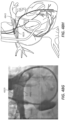
- the configuration of the catheter and electrode systems of the present disclosure may advantageously allow for a portion of the catheter to be positioned within the vasculature of the patient in the main pulmonary artery and/or one or both of the pulmonary arteries (the right pulmonary artery and the left pulmonary artery).
- the catheter and electrode systems of the present disclosure can provide electrical stimulation energy (e.g., electrical current or electrical pulses) to stimulate the autonomic nerve fibers surrounding the main pulmonary artery and/or one or both of the pulmonary arteries in an effort to provide adjuvant cardiac therapy to the patient.
- electrical stimulation energy e.g., electrical current or electrical pulses
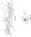
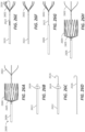
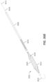
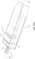
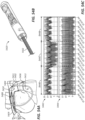
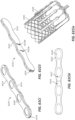
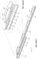
- the catheter can include an elongate body having a first end and a second end.
- the elongate body can include an elongate radial axis that extends through the first end and the second end of the elongate body, and a first plane extends through the elongate radial axis.
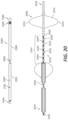
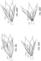
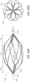
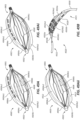
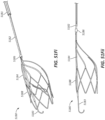
- At least two elongate stimulation members may extend from the elongate body, where each of the at least two elongate stimulation members curves into a first volume defined at least in part by the first plane.
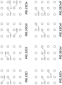
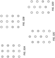
- at least one electrode is on each of the at least two elongate stimulation members, where the at least one electrode form an electrode array in the first volume.
- Conductive elements may extend through and/or along each of the elongate stimulation members, where the conductive elements conduct electrical current to combinations of two or more of the electrodes in the electrode array.
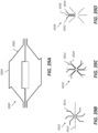
- the at least two elongate stimulation members can curve only in the first volume defined at least in part by the first plane, and a second volume defined at least in part by the first plane and being opposite the first volume contains no electrodes.
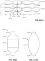
- a second plane can perpendicularly intersect the first plane along the elongate radial axis of the elongate body to divide the first volume into a first quadrant volume and a second quadrant volume.
- the at least two elongate stimulation members can include a first elongate stimulation member and a second elongate stimulation member, where the first elongate stimulation member curves into the first quadrant volume and the second elongate stimulation member curves into the second quadrant volume.
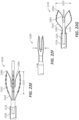
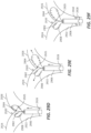
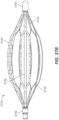
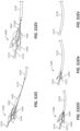
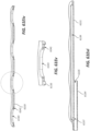
- Each of the at least two elongate stimulation members can include a stimulation member elongate body and a wire extending longitudinally through the elongate body and the stimulation member elongate body, where pressure applied by the wire against the stimulation member elongate body at or near its distal end causes the wire to deflect, thereby imparting the curve into each of the at least two elongate stimulation members into the first volume defined at least in part by the first plane.
- the catheter can also include an anchor member that extends from the elongate body into a second volume defined at least in part by the first plane and opposite the first volume, where the anchor member does not include an electrode.
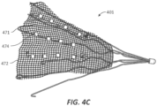
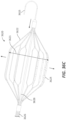
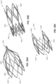
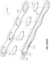
- the catheter can also include a structure extending between at least two of the least two elongate stimulation members.
- An additional electrode can be positioned on the structure, the additional electrode having a conductive element extending from the additional electrode through one of the elongate stimulation members, where the conductive element conducts electrical current to combinations of the additional electrode and at least one of the at least one electrode on each of the at least two elongate stimulation members.
- An example of such a structure is a mesh structure.
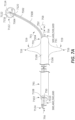
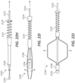
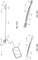
- the catheter can also include a positioning gauge that includes an elongate gauge body with a first end and a bumper end distal to the first end.
- the elongate body of the catheter can include a first lumen that extends from the first end through the second end of the elongate body.
- the bumper end can have a shape with a surface area no less than a surface area of the distal end of the elongate body taken perpendicularly to the elongate radial axis, and the elongate gauge body can extend through the first lumen of the elongate body to position the bumper end beyond the second end of the elongate body.
- the first end of the positioning gauge extends from the first end of the elongate body, the elongate gauge body having a marking that indicates a length between the second end of the elongate body and the bumper end of the positioning gauge.
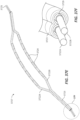
- the present disclosure also includes a catheter system that includes a catheter and a pulmonary artery catheter having a lumen, where the catheter extends through the lumen of the pulmonary artery catheter.
- the pulmonary artery catheter can include an elongate catheter body with a first end, a second end, a peripheral surface and an interior surface, opposite the peripheral surface, that defines the lumen extending between the first end and the second end of the elongate catheter body.
- An inflatable balloon can be positioned on the peripheral surface of the elongate catheter body, the inflatable balloon having a balloon wall with an interior surface that, along with a portion of the peripheral surface of the elongate catheter body, defines a fluid tight volume.
- An inflation lumen extends through the elongate catheter body, the inflation lumen having a first opening into the fluid tight volume of the inflatable balloon and a second opening proximal to the first opening to allow for a fluid to move in and out of the fluid tight volume to inflate and deflate the balloon.
- the present disclosure also provides for a catheter that includes an elongate catheter body having a first end, a second end, a peripheral surface and an interior surface defining an inflation lumen that extends at least partially between the first end and the second end of the elongate catheter body; an inflatable balloon on the peripheral surface of the elongate catheter body, the inflatable balloon having a balloon wall with an interior surface that along with a portion of the peripheral surface of the elongate catheter body defines a fluid tight volume, where the inflation lumen has a first opening into the fluid tight volume of the inflatable balloon and a second opening proximal to the first opening to allow for a fluid to move in the volume to inflate and deflate the balloon; a plurality of electrodes positioned along the peripheral surface of the elongate catheter body, the plurality of electrodes located between the inflatable balloon and the first end of the elongate catheter body; conductive elements extending through the elongate catheter body, where the conductive elements conduct electrical current to combinations of two or more of the at least one electrode of
- the first anchor is positioned between the inflatable balloon and the plurality of electrodes positioned along the peripheral surface of the elongate catheter body.
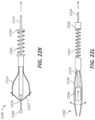
- a portion of the elongate catheter body that includes the plurality of electrodes can curve in a predefined radial direction when placed under longitudinal compression.
- the first anchor is positioned between the plurality of electrodes positioned along the peripheral surface of the elongate catheter body and the first end of the elongate catheter body.
- the elongate catheter body can also include a second interior surface defining a shaping lumen that extends from the first end towards the second end.
- a shaping wire having a first end and a second end can pass through the shaping lumen with the first end of the shaping wire proximal to the first end of the elongate catheter body and the second end of the shaping wire joined to the elongate catheter body so that the shaping wire imparts a curve into a portion of the elongate catheter body having the plurality of electrodes when tension is applied to the shaping wire.
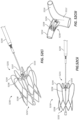
- An example of the catheter can also include an elongate catheter body having a first end, a second end, a peripheral surface and an interior surface defining an inflation lumen that extends at least partially between the first end and the second end of the elongate catheter body; an inflatable balloon on the peripheral surface of the elongate catheter body, the inflatable balloon having a balloon wall with an interior surface that along with a portion of the peripheral surface of the elongate catheter body defines a fluid tight volume, where the inflation lumen has a first opening into the fluid tight volume of the inflatable balloon and a second opening proximal to the first opening to allow for a fluid to move in the volume to inflate and deflate the balloon; a first anchor extending laterally from the peripheral surface of the elongate catheter body the first anchor having struts forming an open framework with a peripheral surface having a diameter larger than a diameter of the inflatable balloon; an electrode catheter having an electrode elongate body and a plurality of electrodes positioned along a peripheral surface of the electrode elong
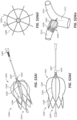
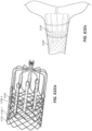
- a catheter system of the present disclosure can also include an elongate catheter body having a first end, a second end, a peripheral surface and an interior surface defining an inflation lumen that extends at least partially between the first end and the second end of the elongate catheter body, where the elongate catheter body includes an elongate radial axis that extends through the first end and the second end of the elongate body, and where a first plane extends through the elongate radial axis; an inflatable balloon on the peripheral surface of the elongate catheter body, the inflatable balloon having a balloon wall with an interior surface that along with a portion of the peripheral surface of the elongate catheter body defines a fluid tight volume, where the inflation lumen has a first opening into the fluid tight volume of the inflatable balloon and a second opening proximal to the first opening to allow for a fluid to move in the volume to inflate and deflate the balloon; an electrode cage having two or more ribs that extend radially away from the peripheral surface of the
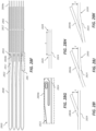
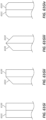
- a catheter in one example, includes an elongate body having a first end and a second end.
- the elongate body includes a longitudinal center axis that extends between the first end and the second end.
- the elongate body further includes three or more surfaces that define a convex polygonal cross-sectional shape taken perpendicularly to the longitudinal center axis.
- the catheter further includes one or more, but preferably two or more, electrodes on one surface of the three or more surfaces of the elongate body, where conductive elements extend through the elongate body.
- the conductive elements can conduct electrical current to combinations of the one or more electrodes or in the instance of a single electrode a second electrode is provided elsewhere in the system for flow of current.
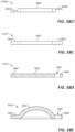
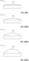
- the surfaces defining the convex polygonal cross-sectional shape of the elongate body can be a rectangle. Other shapes are possible.
- the one or two or more electrodes are only on the one surface of the three or more surfaces of the elongate body.
- the one or more electrodes can have an exposed face that is co-planar with the one surface of the three or more surfaces of the elongate body.
- the one surface of the three or more surfaces of the elongate body can further include anchor structures that extend above the one surface.
- the elongate body of the catheter can also have a portion with a circular cross-section shape taken perpendicularly to the longitudinal center axis.
- the catheter of this example can also include an inflatable balloon on a peripheral surface of the elongate body.
- the inflatable balloon includes a balloon wall with an interior surface that along with a portion of the peripheral surface of the elongate body defines a fluid tight volume.
- An inflation lumen extends through the elongate body, the inflation lumen having a first opening into the fluid tight volume of the inflatable balloon and a second opening proximal to the first opening to allow for a fluid to move in the fluid tight volume to inflate and deflate the balloon.
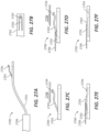
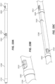
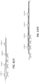
- a catheter in another example, includes an elongate body having a peripheral surface and a longitudinal center axis extending between a first end and a second end.
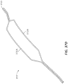
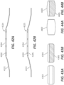
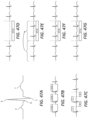
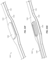
- the elongate body of this example has an offset region defined by a series of predefined curves along the longitudinal center axis.
- the predefined curves include a first portion having a first curve and a second curve in the longitudinal center axis, a second portion following the first portion, where the second portion has a zero curvature (e.g., a straight portion), and a third portion following the second portion, the third portion having a third curve and a fourth curve.
- An inflatable balloon is positioned on the peripheral surface of the elongate body, the inflatable balloon having a balloon wall with an interior surface that along with a portion of the peripheral surface of the elongate body defines a fluid tight volume.
- An inflation lumen extends through the elongate body, the inflation lumen having a first opening into the fluid tight volume of the inflatable balloon and a second opening proximal to the first opening to allow for a fluid to move in the fluid tight volume to inflate and deflate the balloon.
- One or more electrodes are positioned on the elongate body along the second portion of the offset region of the elongate body. Conductive elements extend through the elongate body, where the conductive elements conduct electrical current to combinations of the one or more electrodes.
- the portions of the elongate body of this example of a catheter can have a variety of shapes.
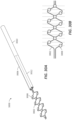
- the second portion of the elongate body can form a portion of a helix.
- the elongate body can also have three or more surfaces defining a convex polygonal cross-sectional shape taken perpendicularly to the longitudinal center axis, where the one or more electrodes are on one surface of the three or more surfaces of the elongate body.
- the convex polygonal cross-sectional shape can be a rectangle.
- the one or more electrodes are only on the one surface of the three or more surfaces of the elongate body.
- the one or more electrodes can have an exposed face that is co-planar with the one surface of the three or more surfaces of the elongate body.
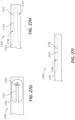
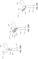
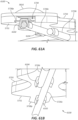
- a catheter in another example, includes an elongate body with a peripheral surface and a longitudinal center axis extending between a first end and a second end.
- the elongate body includes a surface defining a deflection lumen, where the deflection lumen includes a first opening and a second opening in the elongate body.
- An inflatable balloon is located on the peripheral surface of the elongate body, the inflatable balloon having a balloon wall with an interior surface that along with a portion of the peripheral surface of the elongate body defines a fluid tight volume.
- An inflation lumen extends through the elongate body, the inflation lumen having a first opening into the fluid tight volume of the inflatable balloon and a second opening proximal to the first opening to allow for a fluid to move in the fluid tight volume to inflate and deflate the balloon.
- One or more electrodes are located on the elongate body, where the second opening of the deflection lumen is opposite the one or more electrodes on the elongate body.
- Conductive elements extend through the elongate body, where the conductive elements conduct electrical current to combinations of the one or more electrodes.
- the catheter also includes an elongate deflection member, where the elongate deflection member extends through the second opening of the deflection lumen in a direction opposite the one or more electrodes on one surface of the elongate body.
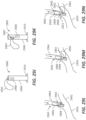
- a catheter in another example, includes an elongate body having a peripheral surface and a longitudinal center axis extending between a first end and a second end.
- the elongate body includes a surface defining an electrode lumen, where the electrode lumen includes a first opening in the elongate body.
- the catheter further includes an inflatable balloon on the peripheral surface of the elongate body, the inflatable balloon having a balloon wall with an interior surface that along with a portion of the peripheral surface of the elongate body defines a fluid tight volume.
- An inflation lumen extends through the elongate body, the inflation lumen having a first opening into the fluid tight volume of the inflatable balloon and a second opening proximal to the first opening to allow for a fluid to move in the fluid tight volume to inflate and deflate the balloon.
- the catheter further includes an elongate electrode member, where the elongate electrode member extends through the first opening of the electrode lumen of the elongate body, where the electrode member includes one or more electrodes and conductive elements extending through the electrode lumen, where the conductive elements conduct electrical current to combinations of the one or more electrodes.
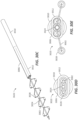
- the elongate electrode member can form a loop that extends away from the peripheral surface of the elongate body.
- the elongate electrode member forming the loop can be in a plane that is co-linear with the longitudinal center axis of the elongate body.
- the elongate electrode member forming the loop is in a plane that is perpendicular to the longitudinal center axis of the elongate body.
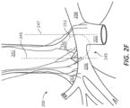
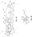
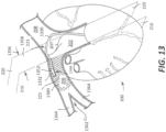
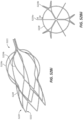
- a catheter having an electrode array is inserted into the pulmonary trunk and positioned at a location such that the electrode array is positioned with its electrodes in contact with the posterior surface, the superior surface and/or the inferior surface of the right pulmonary artery. From this location, electrical current can be delivered to or from the electrode array to selectively modulate the autonomic nervous system of the heart. For example, electrical current can be delivered to or from the electrode array to selectively modulate the autonomic cardiopulmonary nerves of the autonomic nervous system, which can modulate heart contractility and/or relaxation, in some examples more than heart rate.
- the electrode array is positioned at a site along the posterior wall and/or superior wall of the right pulmonary artery such that the electrical current delivered to or from the electrode array results in the greatest effect on heart contractility and/or relaxation and the least effect on heart rate and/or oxygen consumption compared to electrical current delivered at other sites in the right pulmonary artery and/or left pulmonary artery.
- the effect on heart contractility is to increase heart contractility.
- the effect on heart relaxation is to increase heart relaxation.
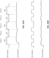
- the electrical current delivered to or from the electrode array can be in the form of a time variant electrical current.
- a time variant electrical current can be in the form of one or more of a pulse of electrical current (e.g., at least one pulse of electrical current), one or more of waveform, such as a continuous wave of electrical current, or a combination thereof.
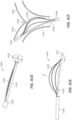
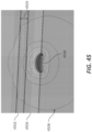
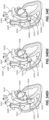
- the present disclosure provides for a method for treating a patient having a heart with a pulmonary trunk.
- Portions of the pulmonary trunk can be defined with a right lateral plane that passes along a right luminal surface of the pulmonary trunk, a left lateral plane parallel with the right lateral plane, where the left lateral plane passes along a left luminal surface of the pulmonary trunk.
- the right lateral plane and the left lateral plane extend in a direction that generally aligns with the posterior and anterior directions of a subject's (e.g., patient's) body.
- a branch point is positioned between the right lateral plane and the left lateral plane, where the branch point helps to define the beginning of a left pulmonary artery and a right pulmonary artery of the heart.
- the method further includes moving a catheter having an electrode array through the pulmonary trunk towards the branch point, where the electrode array includes one or more, preferably two or more, electrodes.
- the electrode array is positioned in the right pulmonary artery to the right of the left lateral plane, where the one or more electrodes contacts a posterior surface, a superior surface and/or an inferior surface of the right pulmonary artery to the right of the left lateral plane.
- the electrode array can be positioned in the right pulmonary artery to the right of the right lateral plane, where the one or more electrodes contacts the posterior surface, the superior surface and/or the inferior surface of the right pulmonary artery to the right of the right lateral plane.
- This example of a method further includes contacting the one or more electrodes on the posterior surface, the superior surface and/or the inferior surface of the right pulmonary artery at a position superior to (e.g., situated above) the branch point.
- the at least a portion of the catheter can also be positioned in contact with a portion of the surface defining the branch point.
- the portion of the catheter can be provided with a shape that provides an increase in surface area that can help to hold the portion of the catheter against the branch point.
- the electrode array can be positioned in the right pulmonary artery between the branch point helping to define the beginning of the left pulmonary artery and the right pulmonary artery and the branch point that divides the right pulmonary artery into at least two additional arteries.
- electrical current can be provided from or to the one or more electrodes of the electrode array.
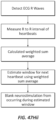
- a value of a cardiac parameter of the patient can be measured in response to the electrical current from or to the one or more electrodes of the electrode array. From the value of the cardiac parameter, changes can be made to which of the electrodes are used to provide the electrical current in response to the value of the cardiac parameter. Changes can also be made to the nature of the electrical current provided in response to the value of the cardiac parameter.
- Such changes include, but are not limited to, changes in voltage, amperage, waveform, frequency and pulse width, by way of example.
- the electrodes of the one or more electrodes on the posterior surface, the superior surface and/or the inferior surface of the right pulmonary artery can be moved in response to the values of the cardiac parameter.
- the electrical current provided to or from the one or more electrodes of the electrode array can be provided as at least one pulse of electrical current to or from the one or more electrodes of the electrode array.
- Examples of such a cardiac parameter include, but are not limited to, measuring a pressure parameter, an acoustic parameter, an acceleration parameter and/or an electrical parameter (e.g., ECG) of the heart of the patient as the cardiac parameter.
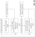
- Several methods of the present disclosure allow for electrical neuromodulation of the heart of the patient, for example including delivering one or more electrical pulses through a catheter positioned in a pulmonary artery of the heart of the patient, sensing from at least a first sensor positioned at a first location within the vasculature of the heart one or more heart activity properties (e.g., a non-electrical heart activity property) in response to the one or more electrical pulses, and adjusting a property of the one or more electrical pulses delivered through the catheter positioned in the pulmonary artery of the heart in response to the one or more heart activity properties.
- the methods may provide adjuvant cardiac therapy to the patient.
- Sensing from at least the first sensor positioned at the first location can include sensing one or more of a pressure property, an acceleration property, an acoustic property, a temperature, and a blood chemistry property from within the vasculature of the heart.
- the first sensor can be positioned in one of a left pulmonary artery, a right pulmonary artery, a pulmonary artery branch vessel, or a pulmonary trunk of the heart.
- the one or more electrical pulses can optionally be delivered through the catheter positioned in one of the left pulmonary artery, the right pulmonary artery, or pulmonary trunk of the heart that does not contain the first sensor.
- the first sensor can also be positioned in a pulmonary trunk of the heart.
- first sensor can include in the right ventricle of the heart and in the right atrium of the heart.
- first sensor When positioned in the right atrium of the heart, the first sensor can optionally be positioned on the septal wall of the right atrium of the heart.
- the first sensor could also be positioned on the septal wall of the right ventricle.
- the right ventricle and the left ventricle share a septal wall, so a sensor in the right ventricle or on the septal wall of the right ventricle may be preferable for detecting properties indicative of left ventricle
- the effect on heart contractility is to increase heart contractility, relaxation, and/or cardiac output.
- Additional locations for positioning the first sensor include in a superior vena cava of the heart, the inferior vena cava of the heart, and in a coronary sinus of the heart.
- the first sensor can be used to sense at least one of a temperature or a blood oxygen level.
- the first sensor may be positioned in the left atrium (e.g., by forming an aperture in the septal wall between the right atrium and the left atrium, or by using a patent foramen ovale (PFO) or atrial septal defect (ASD)).
- a sensor in the left atrium may be useful for detecting properties indicative of the left ventricle. If the left atrium has been accessed, in some examples, the sensor may be positioned in the left ventricle itself, which may provide the most direct measurement of properties associated with the left ventricle. In some examples, the sensor may be positioned downstream of the left ventricle, including the aorta, aortic branch arteries, etc.
- any aperture that was created or existing may be closed using a closure device such as Amplatzer, Helex, CardioSEAL, or others.
- Other measurements of left ventricle contractility can include invasive methods, for example, positioning a strain gauge on the myocardium to measure changes in myocardial stretch, positioning an electrode in proximity to a left stellate ganglion to measure single or multi-unit activity, and/or positioning a cuff electrode around sympathetic fibers to measure neural activity, for example compound action potentials.
- Some methods can include sensing one or more cardiac properties from a skin surface of the patient, and adjusting the property of the one or more electrical pulses delivered through the catheter positioned in the pulmonary artery of the heart in response to the one or more heart activity properties (e.g., non-electrical properties) from the first sensor positioned at a first location within the vasculature of the heart and/or the one or more cardiac properties from the skin surface of the patient.
- the one or more cardiac properties sensed from the skin surface of the patient can include, for example, an electrocardiogram property.
- Some methods can include sensing from at least a second sensor positioned at a second location within the vasculature of the heart one or more heart activity properties (e.g., non-electrical heart activity properties) in response to the one or more electrical pulses, and adjusting the property of the one or more electrical pulses delivered through the catheter positioned in the pulmonary artery of the heart in response to the one or more heart activity properties from the first sensor and/or the one or more heart activity properties from the second sensor.
- heart activity properties e.g., non-electrical heart activity properties
- Adjusting the property of the one or more electrical pulses can include a variety of responses.
- adjusting the property of the one or more electrical pulses can include changing which of an electrode or plurality of electrodes on the catheter is used to deliver the one or more electrical pulses.
- adjusting the property of the one or more electrical pulses can include moving the catheter to reposition one or more electrodes of the catheter in the pulmonary artery of the heart.
- adjusting the property of the one or more electrical pulses can include changing at least one of an electrode polarity, a pulsing mode, a pulse width, an amplitude, a frequency, a phase, a voltage, a current, a duration, an inter-pulse interval, a duty cycle, a dwell time, a sequence, a wavelength, and/or a waveform of the one or more electrical pulses.
- a hierarchy of electrode configurations can be assigned from which to deliver the one or more electrical pulses.
- the one or more electrical pulses can be delivered based on the hierarchy of electrode configurations, where the one or more heart activity properties sensed in response to the one or more electrical pulses can be analyzed and an electrode configuration can be selected to use for delivering the one or more electrical pulses through the catheter positioned in the pulmonary artery of a heart of a patient based on the analysis.
- a hierarchy can be assigned to each property of the one or more electrical pulses delivered through the catheter positioned in the pulmonary artery of the heart, where the one or more electrical pulses are delivered based on the hierarchy of each property.
- the one or more non-electrical heart activity properties sensed in response to the one or more electrical pulses are analyzed and an electrode configuration can be selected to be used for delivering the one or more electrical pulses through the catheter positioned in the pulmonary artery of a heart of a patient based on the analysis.
- Analyzing the one or more heart activity properties can include analyzing a predetermined number of the one or more heart activity properties.
- a method of facilitating therapeutic neuromodulation of a heart of a patient comprises positioning an electrode in a pulmonary artery of a heart and positioning a sensor in a right ventricle of the heart.
- the method further comprises delivering, via a stimulation system, a first series of electrical signals to the electrode.
- the first series comprises a first plurality of electrical signals.
- Each of the first plurality of electrical signals comprises a plurality of parameters.
- Each of the first plurality of electrical signals of the first series only differs from one another by a magnitude of a first parameter of the plurality of parameters.
- the method further comprises, after delivering the first series of electrical signals to the electrode, delivering, via the stimulation system, a second series of electrical signals to the electrode.
- the second series comprises a second plurality of electrical signals.
- Each of the second plurality of electrical signals comprises the plurality of parameters.
- Each of the second plurality of electrical signals of the second series only differs from one another by a magnitude of a second parameter of the plurality of parameters.
- the second parameter is different than the first parameter.
- the method further comprises determining, via the sensor, sensor data indicative of one or more non-electrical heart activity properties in response to delivering the first series of electrical signals and the second series of electrical signals, and delivering a therapeutic neuromodulation signal to the pulmonary artery using selected electrical parameters.
- the selected electrical parameters comprise a selected magnitude of the first parameter and a selected magnitude of the second parameter.
- the selected magnitudes of the first and second parameters are based at least partially on the sensor data.
- the therapeutic neuromodulation signal increases heart contractility and/or relaxation, in some examples more than heart rate.
- the method may further comprise delivering, via the stimulation system, a third series of electrical signals to the electrode.
- the third series comprises a third plurality of electrical signals.
- Each of the third plurality of electrical signals comprises the plurality of parameters.
- Each of the third plurality of electrical signals of the third series only differs from one another by a magnitude of a third parameter of the plurality of parameters.
- the third parameter is different than the first parameter and the second parameter.
- the method may further comprise determining, via the sensor, sensor data indicative of the one or more non-electrical heart activity properties in response to delivering the third series of electrical signals.
- the selected electrical parameters may comprise a selected magnitude of the third parameter.
- the selected magnitude of the third parameter is based at least partially on the sensor data.
- the method may further comprise determining a desired hierarchy between the first series and the second series.
- the pulmonary artery may comprise a right pulmonary artery.
- the one or more non-electrical heart activity properties may comprise at least one of a pressure property, an acceleration property, an acoustic property, a temperature, and a blood chemistry property.
- Determining the sensor data may comprise determining, via a second sensor on a skin surface, sensor data indicative of an electrocardiogram property in response to delivering the first series of electrical signals and the second series of electrical signals.
- the first parameter may be one of the following: a polarity, a pulsing mode, a pulse width, an amplitude, a frequency, a phase, a voltage, a current, a duration, an inter-pulse interval, a duty cycle, a dwell time, a sequence, a wavelength, a waveform, or an electrode combination
- the second parameter may be a different one of the following: a polarity, a pulsing mode, a pulse width, an amplitude, a frequency, a phase, a voltage, a current, a duration, an inter-pulse interval, a duty cycle, a dwell time, a sequence, a wavelength, a waveform, or an electrode combination.
- the second parameter may be one of the following: a polarity, a pulsing mode, a pulse width, an amplitude, a frequency, a phase, a voltage, a current, a duration, an inter-pulse interval, a duty cycle, a dwell time, a sequence, a wavelength, a waveform, or an electrode combination.
- the first parameter may comprise current and the second parameter may comprise a parameter relating to timing (e.g., one of frequency and duty cycle).
- a method of facilitating therapeutic neuromodulation of a heart of a patient comprises positioning an electrode in a pulmonary artery of a heart, positioning a sensor in a right ventricle of the heart, delivering, via a stimulation system, a first electrical signal of a series of electrical signals to the electrode, and, after delivering the first electrical signal, delivering, via the stimulation system, a second electrical signal of the series of electrical signals to the electrode.
- the second electrical signal differs from the first electrical signal by a magnitude of a first parameter of a plurality of parameters.
- the method further comprises determining, via the sensor, sensor data indicative of one or more non-electrical heart activity properties in response to the delivery of the series of electrical signals, and delivering a therapeutic neuromodulation signal to the pulmonary artery using selected electrical parameters.
- the selected electrical parameters comprise a selected magnitude of the first parameter.
- the selected magnitude of the first parameter is based at least partially on the sensor data.
- the therapeutic neuromodulation signal increases heart contractility and/or relaxation, in some examples more than heart rate.
- the pulmonary artery may comprise a right pulmonary artery.
- the pulmonary artery may comprise a left pulmonary artery.
- the pulmonary artery may comprise a pulmonary trunk.
- the one or more non-electrical heart activity properties may comprise at least one of a pressure property, an acceleration property, an acoustic property, a temperature, and a blood chemistry property.
- Determining the sensor data may comprise determining, via a second sensor on a skin surface of the patient, sensor data indicative of an electrocardiogram property in response to delivering the series of electrical signals.
- the first parameter may be one of the following: a polarity, a pulsing mode, a pulse width, an amplitude, a frequency, a phase, a voltage, a current, a duration, an inter-pulse interval, a duty cycle, a dwell time, a sequence, a wavelength, a waveform, or an electrode combination.
- a method of facilitating therapeutic neuromodulation of a heart of a patient comprises delivering a first series of electrical signals to an electrode in a first anatomical location, and, after delivering the first series of electrical signals to the electrode, delivering a second series of electrical signals to the electrode.
- the first series comprises a first plurality of electrical signals.
- Each of the first plurality of electrical signals comprises a plurality of parameters.
- Each of the first plurality of electrical signals of the first series only differs from one another by a magnitude of a first parameter of the plurality of parameters.
- the second series comprises a second plurality of electrical signals.
- Each of the second plurality of electrical signals comprises the plurality of parameters.
- Each of the second plurality of electrical signals of the second series only differs from one another by a magnitude of a second parameter of the plurality of parameters.
- the second parameter is different than the first parameter.
- the method further comprises sensing, via a sensor in a second anatomical location different than the first anatomical location, sensor data indicative of one or more non-electrical heart activity properties in response to delivering the first series of electrical signals and the second series of electrical signals, and providing a therapeutic neuromodulation signal to the first anatomical location using selected electrical parameters.
- the selected electrical parameters comprise a selected magnitude of the first parameter and a selected magnitude of the second parameter.
- the selected magnitudes of the first and second parameters are based at least partially on the sensor data.
- the therapeutic neuromodulation signal increases heart contractility and/or relaxation.
- the method may further comprise delivering a third series of electrical signals to the electrode.
- the third series comprises a third plurality of electrical signals.
- Each of the third plurality of electrical signals comprises the plurality of parameters.
- Each of the third plurality of electrical signals of the third series only differs from one another by a magnitude of a third parameter of the plurality of parameters.
- the third parameter is different than the first parameter and the second parameter.
- the method may further comprise sensing, via the sensor, sensor data indicative of the one or more non-electrical heart activity properties in response to delivering the third series of electrical signals.
- the selected electrical parameters may comprise a selected magnitude of the third parameter.
- the selected magnitude of the third parameter is based at least partially on the sensor data.
- the method may further comprise determining a desired hierarchy between the first series and the second series.
- the first anatomical location may comprise a right pulmonary artery.
- the pulmonary artery may comprise a left pulmonary artery.
- the pulmonary artery may comprise a pulmonary trunk.
- the one or more non-electrical heart activity properties may comprise at least one of a pressure property, an acceleration property, an acoustic property, a temperature, and a blood chemistry property.
- Sensing the sensor data may comprise determining, via a second sensor on a skin surface, sensor data indicative of an electrocardiogram property in response to delivering the first series of electrical signals and the second series of electrical signals.
- the first parameter may one of the following: a polarity, a pulsing mode, a pulse width, an amplitude, a frequency, a phase, a voltage, a current, a duration, an inter-pulse interval, a duty cycle, a dwell time, a sequence, a wavelength, a waveform, or an electrode combination
- the second parameter may be a different one of the following: a polarity, a pulsing mode, a pulse width, an amplitude, a frequency, a phase, a voltage, a current, a duration, an inter-pulse interval, a duty cycle, a dwell time, a sequence, a wavelength, a waveform, or an electrode combination.
- the second parameter may one of the following: a polarity, a pulsing mode, a pulse width, an amplitude, a frequency, a phase, a voltage, a current, a duration, an inter-pulse interval, a duty cycle, a dwell time, a sequence, a wavelength, a waveform, or an electrode combination.
- the first parameter may comprise current and the second parameter may comprise a parameter related to timing (e.g., one of frequency and duty cycle).
- a method of facilitating therapeutic neuromodulation of a heart of a patient comprises delivering a first electrical signal of a series of electrical signals to an electrode in a first anatomical location, and, after delivering the first electrical signal, delivering a second electrical signal of the series of electrical signals to the electrode.
- the second electrical signal differs from the first electrical signal by a magnitude of a first parameter of a plurality of parameters.
- the method further comprises sensing, via a sensor in a second anatomical location different than the first anatomical location, sensor data indicative of one or more non-electrical heart activity properties in response to the delivery of the series of electrical signals, and providing a therapeutic neuromodulation signal to the first anatomical location using selected electrical parameters.
- the selected electrical parameters comprise a selected magnitude of the first parameter.
- the selected magnitude of the first parameter is based at least partially on the sensor data.
- the therapeutic neuromodulation signal increases heart contractility and/or relaxation.
- the first anatomical location may comprise a right pulmonary artery.
- the first anatomical location may comprise a left pulmonary artery.
- the first anatomical location may comprise a pulmonary trunk.
- the one or more non-electrical heart activity properties may comprise at least one of a pressure property, an acceleration property, an acoustic property, a temperature, and a blood chemistry property.
- Sensing the sensor data may comprise sensing, via a second sensor on a skin surface of the patient, sensor data indicative of an electrocardiogram property in response to delivering the series of electrical signals.
- the first parameter may be one of the following: a polarity, a pulsing mode, a pulse width, an amplitude, a frequency, a phase, a voltage, a current, a duration, an inter-pulse interval, a duty cycle, a dwell time, a sequence, a wavelength, a waveform, or an electrode combination.
- the catheter comprises a catheter body comprising a proximal end, a distal end, a lumen extending from the proximal end towards the distal end, and an outer surface.
- the catheter further comprises an electrode on the outer surface.
- the electrode is configured to deliver an electrical signal to a pulmonary artery of a patient.
- the catheter further comprises a sensor on the outer surface. The sensor is configured to sense a heart activity property from a location within in vasculature of the patient.
- the stimulation system comprises a pulse generator configured to deliver a first series of electrical signals and a second series of electrical signals to the electrode.
- the first series comprises a first plurality of electrical signals.
- Each of the first plurality of electrical signals comprises a plurality of parameters.
- Each of the first plurality of electrical signals of the first series only differs from one another by a magnitude of a first parameter of the plurality of parameters.
- the second series comprises a second plurality of electrical signals.
- Each of the second plurality of electrical signals comprises the plurality of parameters.
- Each of the second plurality of electrical signals of the second series only differs from one another by a magnitude of a second parameter of the plurality of parameters.
- the second parameter is different than the first parameter.
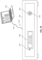
- the stimulation system further comprises a non-transitory computer-readable medium configured to store sensor data indicative of one or more non-electrical heart activity properties in response to delivering the first series of electrical signals and the second series of electrical signals to the electrode, and a processor configured to determine a selected magnitude of the first parameter and a selected magnitude of the second parameter based at least partially on the sensor data.
- the non-transitory computer readable medium is configured to store selected electrical parameters including the selected magnitude of the first parameter and the selected magnitude of the second parameter.
- the pulse generator is configured to deliver a therapeutic neuromodulation signal to the electrode using selected electrical parameters.
- the catheter comprises a catheter body comprising a proximal end, a distal end, a lumen extending from the proximal end towards the distal end, and an outer surface.
- the catheter further comprises an electrode on the outer surface.
- the electrode is configured to deliver an electrical signal to a pulmonary artery of a patient.
- the catheter further comprises a sensor on the outer surface.
- the sensor is configured to sense a heart activity property from a location within in vasculature of the patient.
- the stimulation system comprises a pulse generator configured to deliver a series of electrical signals to the electrode.
- the series comprises a first electrical signal and a second electrical signal.
- the second electrical signal differs from the first electrical signal by a magnitude of a first parameter of a plurality of parameters.
- the stimulation system further comprises a non-transitory computer-readable medium configured to store sensor data indicative of one or more non-electrical heart activity properties in response to delivering the series of electrical signals to the electrode, and a processor configured to determine a selected magnitude of the first parameter based at least partially on the sensor data.
- the non-transitory computer readable medium is configured to store selected electrical parameters including the selected magnitude of the first parameter.
- the pulse generator is configured to deliver a therapeutic neuromodulation signal to the electrode using selected electrical parameters.
- a neuromodulation system for facilitating delivery of electric signals to a heart of a patient comprises a catheter and a shaping wire.
- the catheter comprises a catheter body comprising a proximal end, a distal end, a lumen extending from the proximal end towards the distal end, and an outer surface.
- the catheter further comprises an electrode on the outer surface.
- the electrode is configured to deliver an electrical signal to a pulmonary artery of a patient.
- the shaping wire is configured to be positioned in the lumen of the catheter body.
- the shaping wire comprises a bent portion. When the shaping wire is inserted in the lumen of the catheter body, the catheter body comprises a curved portion corresponding to the bent portion of the shaping wire.
- the heart activity property may comprise a non-electrical hearty activity property.
- the non-electrical heart activity property may comprise at least one of a pressure property, an acceleration property, an acoustic property, a temperature, and a blood chemistry property.
- the electrode may be configured to deliver the electrical signal to a right pulmonary artery of the patient.
- the electrode may be configured to be positioned in a different location than the sensor.
- the catheter system may comprise a plurality of electrodes including the electrode.
- the location may be a pulmonary trunk, a right ventricle, a septal wall of a right ventricle, a right atrium, a septal wall of a right atrium, a superior vena cava, a pulmonary branch artery vessel, an inferior vena cava, or a coronary sinus.
- the neuromodulation system may further comprise a skin sensor configured to sense a cardiac property from a skin surface of the patient.
- the heart activity property may comprise a non-electrical heart activity property and wherein the cardiac property may comprise an electrical cardiac property.
- the electrical cardiac property may comprise an electrocardiogram property.
- a method of neuromodulation of a heart of a patient comprises positioning a catheter including an electrode in a pulmonary artery of a heart, positioning a sensor in a location within vasculature of the heart, delivering, via a stimulation system, a first set of one or more electrical pulses to the electrode, the first set of one or more electrical pulses having a first pulse property, and, after delivering the first delivering set of one or more electrical pulses to the electrode, delivering, via the stimulation system, a second set of one or more electrical pulses to the electrode.
- the second set of one or more electrical pulses has a second pulse property different than the first pulse property.
- the method further comprises delivering therapeutic electrical pulses to the pulmonary artery using an electrode configuration selected by analyzing one or more heart activity properties sensed, via the sensor, in response to the delivery of the first and second sets of electrical pulses.
- the electrode configuration comprises the first pulse property or the second pulse property based at least partially on the analysis.
- the therapeutic neuromodulation signal increases heart contractility and/or relaxation, in some examples more than heart rate.
- a method of modulation (e.g., electrical neuromodulation) of a heart of a patient comprises delivering one or more electrical pulses through a catheter positioned in a pulmonary artery of the heart of the patient, sensing from at least a first sensor positioned at a first location within a vasculature of the heart one or more non-electrical heart activity properties in response to the one or more electrical pulses, and adjusting a property of the one or more electrical pulses delivered through the catheter positioned in the pulmonary artery of the heart in response to the one or more non-electrical heart activity properties.
- sensing from at least the first sensor positioned at the first location may include sensing one or more of a pressure property, an acceleration property, an acoustic property, a temperature, and a blood chemistry property from within the vasculature of the heart.
- a first sensor is placed in one of a left pulmonary artery, a right pulmonary artery, or a pulmonary trunk of the heart.
- One or more electrical pulses are delivered through the catheter positioned in one of the left pulmonary artery, the right pulmonary artery, or the pulmonary trunk of the heart that does not contain the first sensor.
- the first sensor may be positioned in the left pulmonary artery.
- the first sensor may be positioned in the right pulmonary artery.
- the first sensor may be positioned in other vessels in and around the heart, including, but not limited to, the pulmonary trunk, a pulmonary artery branch vessel, right ventricle, a septal wall of the right ventricle, a right atrium, the septal wall of the right atrium, a superior vena cava, an inferior vena cava or a coronary sinus
- the first sensor (e.g., in the coronary sinus) may sense at least one of a temperature or a blood oxygen level.
- the method may include sensing one or more cardiac properties from a skin surface of the patient and adjusting the property of the one or more electrical pulses delivered through the catheter positioned in the pulmonary artery of the heart in response to the one or more non-electrical heart activity properties and the one or more cardiac properties from the skin surface of the patient.
- the one or more cardiac properties sensed from the skin surface of the patient may include an electrocardiogram property.
- The may include sensing from at least a second sensor positioned at a second location within the vasculature of the heart one or more non-electrical heart activity properties in response to the one or more electrical pulses and adjusting the property of the one or more electrical pulses delivered through the catheter positioned in the pulmonary artery of the heart in response to the one or more non-electrical heart activity properties received by the first sensor and the second sensor.
- adjusting the property of the one or more electrical pulses may include one or more of the following (i) changing which electrode on the catheter is used to deliver the one or more electrical pulses; (ii) moving the catheter to reposition electrodes of the catheter in the pulmonary artery of the heart; (iii) changing at least one of an electrode polarity, a pulsing mode, a pulse width, an amplitude, a frequency, a phase, a voltage, a current, a duration, an inter-pulse interval, a duty cycle, a dwell time, a sequence, a wavelength, a waveform, or an electrode combination of the one or more electrical pulses.
- the method may include assigning a hierarchy of electrode configurations from which to deliver the one or more electrical pulses, delivering the one or more electrical pulses based at least partially on the hierarchy of electrode configurations, analyzing the one or more non-electrical heart activity properties sensed in response to the one or more electrical pulses, and selecting an electrode configuration to use for delivering the one or more electrical pulses through the catheter positioned in the pulmonary artery of a heart of a patient based at least partially on the analysis.
- therapeutic neuromodulation is not provided. Instead, several examples are provided for the purposes of calibrating or optimizing a signal for, e.g., diagnosis or calibration purposes.
- a method of non-therapeutic calibration comprises positioning an electrode in a pulmonary artery of a heart and positioning a sensor in a right ventricle of the heart.
- the system further comprises delivering, via a stimulation system, a first series of electrical signals to the electrode.
- the first series comprises a first plurality of electrical signals.
- Each of the first plurality of electrical signals comprises a plurality of parameters.
- Each of the first plurality of electrical signals of the first series only differs from one another by a magnitude of a first parameter of the plurality of parameters.
- the method further comprises, after delivering the first series of electrical signals to the electrode, delivering, via the stimulation system, a second series of electrical signals to the electrode.
- the second series comprises a second plurality of electrical signals.
- Each of the second plurality of electrical signals comprises the plurality of parameters.
- Each of the second plurality of electrical signals of the second series only differs from one another by a magnitude of a second parameter of the plurality of parameters.
- the second parameter is different than the first parameter.
- the method further comprises determining, via the sensor, sensor data indicative of one or more non-electrical heart activity properties in response to delivering the first series of electrical signals and the second series of electrical signals.
- the method further comprises determining a therapeutic neuromodulation signal to be delivered to the pulmonary artery using selected electrical parameters.
- the selected electrical parameters comprise a selected magnitude of the first parameter and a selected magnitude of the second parameter.
- the selected magnitudes of the first and second parameters are based at least partially on the sensor data.
- a method of non-therapeutic calibration comprises delivering a first electrical signal of a series of electrical signals to an electrode in a first anatomical location and, after delivering the first electrical signal, delivering a second electrical signal of the series of electrical signals to the electrode.
- the second electrical signal differs from the first electrical signal by a magnitude of a first parameter of a plurality of parameters.
- the method further comprises sensing, via a sensor in a second anatomical location different than the first anatomical location, sensor data indicative of one or more non-electrical heart activity properties in response to the delivery of the series of electrical signals, and determining a therapeutic neuromodulation signal to be delivered to the first anatomical location using selected electrical parameters.
- the selected electrical parameters comprise a selected magnitude of the first parameter.
- the selected magnitude of the first parameter is based at least partially on the sensor data.
- a device comprises or consists essentially of a first part and a second part.
- the first part comprises a first annular portion having a first diameter and a first plurality of splines extending distally from the first annular portion.
- the second part comprises a second annular portion having a second diameter and a second plurality of splines extending distally and radially outward from the second annular portion.
- the second diameter is less than the first diameter.
- the second annular portion is telescopeable in the first annular portion.
- Each of the first plurality of splines is coupled to one spline of the second plurality of splines.
- the first part Upon distal longitudinal advancement of the second part relative to the first part, the first part expands from a collapsed state to an expanded state.
- the first plurality of splines is circumferentially spaced in the expanded state.
- the first part Upon proximal longitudinal retraction of the second part relative to the first part, the first part collapses from the expanded state to the collapsed state.
- a distal end of each of the first plurality of splines may be coupled to one spline of the second plurality of splines.
- each of the first plurality of splines may be coupled to one spline of the second plurality of splines proximal to a distal end of the one of the second plurality of splines.
- the distal ends of the second plurality of splines may comprise fixation elements.
- At least some of the first plurality of splines may comprise electrodes.
- Each spline of the first plurality of splines may comprise a plurality of electrodes.
- the plurality of electrodes may at least partially forming an electrode matrix.
- the device may further comprise a membrane coupled to the first plurality of splines, the membrane comprising a plurality of electrodes, the plurality of electrodes at least partially forming an electrode matrix.
- a longitudinal length from a proximal end of a proximal-most electrode of the plurality of electrodes to a distal end of a distal-most electrode the plurality of electrodes may be between 20 mm and 40 mm.
- a diameter of the first plurality of splines in the expanded state may be between 15 mm and 35 mm.
- the device may further comprise a catheter coupled to the first annular portion and an inner member in a lumen of the catheter and coupled to the second annular portion.
- the inner member may be movable relative to the catheter to distally advance and proximally retract the second part.
- a proximal end of the first annular portion may be coupled in a distal end of a lumen of the catheter.
- a proximal end of the second annular portion may be coupled in a distal end of a lumen of the inner member.
- the inner member may be trackable over a guidewire.
- the device may further comprise a gripper coupled to the inner member, a spring engaging the gripper, and a handle element coupled to the inner member.
- the spring may be longitudinally expanded, the inner member may be distally longitudinally advanced, the second part may be distally longitudinally advanced, and the first part may expand from the collapsed state to the expanded state.
- the spring may be longitudinally compressed, the inner member may be proximally longitudinally retracted, the second part may be proximally longitudinally retracted, and the first part collapses from the expanded state to the collapsed state.
- the spring may be configured to at least partially proximally retract the handle element.
- the device may further comprise a locking mechanism configured to maintain the handle element in a distally advanced state.
- the locking element may comprise a plurality of arms having an open proximal end.
- the handle element may be configured to extend through the open proximal end upon distal advancement.
- the locking element may comprise a plurality of arms having closed proximal end.
- the handle element may be configured to engage the closed proximal end upon distal advancement.
- the plurality of arms may comprise leaf springs. The leaf springs may be configured to at least partially proximally retract the handle element.
- the first plurality of splines may be not self-expanding.
- the first plurality of splines may be self-expanding.
- the first plurality of splines may comprise a non-tapered shape in the expanded state.
- the first part may comprise a first cut hypotube.
- the first annular portion may comprise a hypotube and the first plurality of splines may comprise a plurality of wires.
- the second part may comprise second a cut hypotube.
- a device comprises or consists essentially of a plurality of splines, a structure coupled to at least one spline of the plurality of splines, and an electrode coupled to the structure.
- the device may comprise a plurality of electrodes coupled to the structure.
- the plurality of electrodes may be the electrode.
- the plurality of electrodes may at least partially form an electrode matrix.
- the electrode matrix may comprise a 3 ⁇ 4 matrix.
- the structure may be coupled to at least two splines of the plurality of splines.
- the electrode may be circumferentially between two splines of the plurality of splines.
- the electrode may be circumferentially aligned with a spline of the plurality of splines.
- the device may further comprise a second electrode coupled to one of the plurality of splines.
- the structure may comprise a plurality of flexible strands connected to form a pattern of openings.
- the structure may comprise a mesh.
- the structure may comprise a woven or knitted membrane.
- the structure may comprise shape memory material having an expanded shape when not confined.
- the structure may comprise insulative material.
- a device comprises or consists essentially of a first sidewall, a second sidewall spaced from the first sidewall, and a third sidewall between the first sidewall and the second sidewall.
- the first sidewall, the second sidewall, and the third sidewall at least partially define a U-shaped trough.
- the device further comprises a plurality of conductors in the trough and an electrode electrically connected to one of the plurality of conductors.
- the device may comprise a plurality of electrodes including the electrode.
- the plurality of electrodes may at least partially form an electrode matrix.
- Each of the plurality of electrodes may be electrically connected to one of the plurality of conductors.
- the electrode may have a dome shape.
- the device may further comprise insulative material between the plurality of conductors and the electrode.
- the device may further comprise insulative material between the plurality of conductors and the third sidewall.
- the device may further comprise insulating material extending at least above a bottom of the electrode.
- the insulating material may comprise a dome shape.
- the insulating material may comprise a flat upper surface.
- the insulating material may comprise a crowned surface.
- the insulating material may cover a sharp edge of the electrode.
- the electrode may have no uninsulated sharp edges.
- the electrode may be configured to be spaced from a vessel wall surface.
- a system comprises a plurality of the devices.
- the plurality of devices may at least partially form an electrode matrix.
- a device comprises or consists essentially of a catheter comprising a lumen, a fixation structure, and a fixation element.
- the fixation structure comprises a first side, a second side, and a twist.
- the fixation element is coupled to the first side of the fixation structure.
- the first side faces radially inwardly when the fixation structure is inside the lumen of the catheter and faces radially outwardly when the fixation structure is outside the lumen of the catheter.
- the lumen may be shaped to correspond to a shape of the fixation structure and the fixation element.
- the twist may be 180°.
- the fixation structure may comprise a ribbon.
- the fixation structure may comprise a strut.
- the fixation structure may be configured to bend radially outward upon deployment from the catheter.
- the fixation element may comprise a conical spike.
- a device may comprise or consists essentially of a fixation structure, a fixation mechanism, and an attachment point coupling the fixation structure to the fixation mechanism.
- the fixation mechanism is configured to turn radially outward upon expansion of the fixation structure.
- the fixation mechanism is configured to turn radially inward upon collapse of the fixation structure. In an expanded state, the fixation mechanism extends radially outward of the fixation structure.
- the fixation mechanism may comprise an aperture.
- the device may further comprise a radiopaque marker coupled to the fixation mechanism.
- the device may further comprise a tether extending proximally from the attachment point.
- Tether may comprise a bend along a longitudinal length of the fixation mechanism. The bend may be between 30% and 70% of the longitudinal length of the fixation mechanism.
- the tether may comprise a ramped portion having a wide edge coupled to the attachment point.
- the tether may comprise a twist proximal to the attachment point.
- the device may further comprise a second fixation mechanism extending distally from the fixation structure.
- the fixation structure, the fixation element, and the attachment point may be monolithically cut from a same hypotube.
- the fixation structure may comprise an electrode.
- the fixation structure may comprise a plurality of electrodes including the electrode. The plurality of electrodes may at least partially form an electrode matrix.
- a method of forming a device comprises or consists essentially of cutting a hypotube to form a fixation structure, a fixation mechanism, and an attachment point coupling the fixation structure and the fixation mechanism, and shape setting an expanded shape.
- the expanded shape includes the fixation mechanism bent radially outward of the fixation structure. After shape setting the expanded shape, the fixation mechanism is configured to turn radially outward upon expansion of the fixation structure and the fixation mechanism is configured to turn radially inward upon collapse of the fixation structure.
- a device comprises or consists essentially of a fixation structure, a fixation arm, and a fixation mechanism coupled to the fixation arm.
- the fixation structure comprises an aperture, a first surface, and a second surface opposite the first surface.
- the fixation arm is coupled to an inside of the aperture of the fixation structure. The fixation arm does not protrude above the first surface in a first state.
- the fixation arm may be configured to flex radially outward when not confined by a catheter.
- the fixation mechanism may protrude above the first surface when the fixation arm is not confined by the catheter.
- the fixation arm may be configured to remain stationary when not confined by a catheter.
- the fixation mechanism may not protrude above the first surface when the fixation arm may be not confined by the catheter.
- the fixation structure and the fixation arm may be formed from a same piece of material.
- the aperture may extend from the first surface to the second surface.
- the aperture may extends from the first surface to a point above the second surface.
- the fixation mechanism may comprise a conical spike.
- the fixation mechanism may comprise a textured surface.
- a device comprises or consists essentially of a catheter comprising a lumen, a first loop longitudinally movable from in the lumen of the catheter to out of the lumen of the catheter, and a second loop longitudinally movable from in the lumen of the catheter to out of the lumen of the catheter.
- At least one of the catheter, the first loop, and the second loop comprises a first electrode.
- At least one of the first loop and the second loop may be a pigtail at an end of a finger.
- the first loop may comprise a first plurality of electrodes including the first electrode.
- the first plurality of electrodes may at least partially form a first electrode matrix.
- the second loop may comprise a second plurality of electrodes.
- the second plurality of electrodes may at least partially form a second electrode matrix.
- the second loop may comprise a second electrode.
- the first loop may comprise a first portion comprising electrodes of the first plurality of electrodes and a second portion comprising electrodes of the first plurality of electrodes.
- the second portion may be spaced from the first portion.
- the second portion may be parallel to the first portion.
- the first loop may comprise an undulating segment comprising peaks and troughs.
- the undulating segment may comprise the first plurality of electrodes.
- the undulating segment may comprise electrodes of the first plurality of electrodes proximate to the peaks and electrodes of the first plurality of electrodes proximate to the troughs.
- the catheter may comprise a plurality of electrodes including the first electrode.
- the first plurality of electrodes may at least partially form a first electrode matrix.
- the first loop and the second loop may be configured to be deployed from the lumen of the catheter at least partially simultaneously.
- the first loop and the second loop may be configured to be deployed from the lumen of the catheter sequentially.
- the device may further comprise a fixation feature extending radially outward from the catheter.
- the fixation feature may comprise an atraumatic stiff loop.
- a method of using the device may comprise or consist essentially of advancing the catheter distal to a pulmonary valve, advancing the catheter distal to the pulmonary valve, deploying the first loop and the second loop, and after deploying the first loop and the second loop, distally advancing the catheter towards a pulmonary artery bifurcation.
- the first loop and the second loop are self-orienting so that one of the first loop and the second loop extends into the right pulmonary artery and the other of the first loop and the second loop extends into the left pulmonary artery.
- the method may further comprise distally advancing the catheter until advancement may be limited by the pulmonary artery bifurcation.
- the method may further comprise extending a fixation feature proximate to the pulmonary valve.
- the method may further comprise attempting to capture a target nerve with the first electrode.
- the method may further comprise, if the target nerve may be not captured, withdrawing the first loop and the second loop into the lumen of the catheter, proximally retracting the catheter, rotating the catheter, after rotating the catheter, redeploying the first loop and the second loop, and, after redeploying the first loop and the second loop, distally advancing the catheter towards the pulmonary artery bifurcation.
- the first loop and the second loop are self-orienting so that one of the first loop and the second loop extends into the right pulmonary artery and the other of the first loop and the second loop extends into the left pulmonary artery in an opposite orientation.
- the method may further comprise, if the target nerve may be not captured, attempting to capture a target nerve with a second electrode.
- a device comprises, or alternatively consists essentially of, a catheter comprising a lumen and a loop longitudinally movable from in the lumen of the catheter to out of the lumen of the catheter. At least one of the catheter and the loop comprises a first electrode.
- the loop may comprise a first plurality of electrodes including the first electrode.
- the first plurality of electrodes may at least partially form a first electrode matrix.
- the loop may comprise a first portion comprising electrodes of the first plurality of electrodes and a second portion comprising electrodes of the first plurality of electrodes.
- the second portion may be spaced from the first portion.
- the second portion may be parallel to the first portion.
- the loop may comprise an undulating segment comprising peaks and troughs.
- the undulating segment may comprise the first plurality of electrodes.
- the undulating segment may comprise electrodes of the first plurality of electrodes proximate to the peaks and electrodes of the first plurality of electrodes proximate to the troughs.
- the catheter may comprise a first plurality of electrodes including the first electrode.
- the first plurality of electrodes may at least partially form a first electrode matrix.
- the loop may be configured to be deployed from the lumen of the catheter out of a distal end of the catheter.
- the loop may be configured to be deployed from the lumen of the catheter out of a side of the catheter.
- the device may further comprise a fixation feature extending radially outward from the catheter.
- the fixation feature may comprise an atraumatic stiff loop.
- the loop may be a pigtail at an end of a finger.
- a method of using the device may comprise deploying the loop out of the lumen of the catheter; after deploying the loop, advancing the catheter in a first branch vessel towards a primary vessel; allowing the loop to radially expand at a bifurcation comprising the first branch vessel, the primary vessel, and a second branch vessel; and after allowing the loop to radially expand, proximally retracting the catheter until the loop contacts the second branch vessel.
- the first branch vessel may comprise the left internal jugular vein
- the primary vessel may comprise the left brachiocephalic vein
- the second branch vessel may comprise the left subclavian vein.
- the method may further comprise extending a fixation feature.
- the method may further comprise attempting to capture a target nerve with the first electrode.
- the target nerve may comprise a thoracic cardiac branch nerve.
- the target nerve may comprise a cervical cardiac nerve.
- a device comprises or consists essentially of a catheter comprising a lumen, a first sinusoidal wire, a second sinusoidal wire radially spaced from the first sinusoidal wire, and a plurality of electrodes.
- Each of the plurality of electrodes may be coupled to at least one the first sinusoidal wire and the second sinusoidal wire.
- the device may further comprise a membrane coupled to the first sinusoidal wire and the second sinusoidal wire.
- Each of the plurality of electrodes may be coupled to the membrane.
- the membrane may be configured to have a curved shape in an expanded state.
- the membrane may comprise a flex circuit including conductor wires.
- the plurality of electrodes may comprise button electrodes.
- the plurality of electrodes may comprise barrel electrodes.
- the plurality of electrodes may comprise cylindrical electrodes.
- the plurality of electrodes may comprise directional electrodes. Centers the plurality of electrodes may be longitudinally offset.
- the catheter may comprise a first segment and a second segment distal to the first segment.
- the first segment may have a circular cross-section.
- the second segment may have an oval cross-section.
- the second segment may be configured to contain the first sinusoidal wire and the second sinusoidal wire.
- the first sinusoidal wire and the second sinusoidal wire may be planar in an expanded state.
- the first sinusoidal wire and the second sinusoidal wire may be at an angle in an expanded state.
- the first sinusoidal wire and the second sinusoidal wire may comprise shape memory material.
- a device comprises, or alternatively consists essentially of, a handle, a sheath, and an electrode system moveable in and out of the sheath.
- the handle comprises a repositioning system.
- the repositioning system comprises a track and a knob slideable within the track.
- the electrode system is configured to move longitudinally upon longitudinal movement of the knob in the track and to move rotationally upon transverse or rotational movement of the knob in the track.
- the track may comprise a longitudinal segment, a first transverse segment extending from the longitudinal segment in a first direction, and a second transverse segment extending from the longitudinal segment in a second direction opposite the first direction.
- the first transverse segment may be longitudinally offset from the second transverse segment.
- the first transverse segment may be longitudinally aligned with the second transverse segment.
- the electrode system may be configured to move a longitudinal distance upon movement of the knob the same longitudinal distance in the track.
- the electrode system may be configured to rotate a circumferential angle upon transverse or rotational movement of the knob in the track.
- the device may further comprise a rotational stop to limit rotation of the electrode system to the circumferential angle.
- the device may further comprise a detent and a groove configured to interact with the detent upon movement of the knob.
- the detent may be configured to produce audible indicia.
- the device may further comprise a physical barrier configured to inhibit accidental movement of the knob.
- a device comprises, or alternatively consists essentially of, an expandable structure having a collapsed state and an expanded state.
- the expandable structure comprises, in the expanded state, a plurality of splines each comprising a proximal segment comprising a first portion, a second portion distal to the first portion, and a third portion distal to the second portion; an intermediate segment distal to the proximal segment; and a distal segment distal to the intermediate segment, the distal segment comprising a fourth portion, a fifth portion distal to the fourth portion, and a sixth portion distal to the fifth portion.
- the first portion is parallel to a longitudinal axis.
- the second portion extends radially outward from the first portion.
- the third portion extends radially outward from the second portion and transverse to the longitudinal axis to the intermediate segment.
- the fourth portion extends from the intermediate segment radially inward and transverse to the longitudinal axis.
- the fifth portion extends radially inward from the fourth portion.
- the sixth portion extends from the fifth portion parallel to a longitudinal axis. At least two of the intermediate segments of the plurality of splines are circumferentially spaced and comprise a plurality of electrodes forming an electrode matrix.
- the expandable structure may be self-expanding.
- the expandable structure may be expandable upon operation of an actuation mechanism.
- the at least two intermediate segments may be parallel to the longitudinal axis. In the expanded state, the at least two intermediate segments may be recessed relative to the longitudinal axis. In the expanded state, the at least two intermediate segments may be crowned relative to the longitudinal axis.
- Pairs of the first portions of the plurality of splines may be parallel. Pairs of the sixth portions of the plurality of splines may be parallel. Pairs of the first portions of the plurality of splines may be twisted. Pairs of the sixth portions of the plurality of splines may be twisted.
- Proximal ends of the intermediate segments of the plurality of splines may be longitudinally aligned. Proximal ends of the intermediate segments of the plurality of splines may be longitudinally offset. Distal ends of the intermediate segments of the plurality of splines may be longitudinally aligned. Distal ends of the intermediate segments of the plurality of splines may be longitudinally offset.
- the plurality of splines may further comprise a spline circumferentially between the at least two intermediate segments.
- the plurality of splines may comprise a plurality of wires.
- the plurality of splines may be formed from a cut hypotube.
- the expandable structure may further comprise a membrane coupled to the at least two intermediate segments.
- the membrane may comprise the electrode matrix.
- the device may further comprise a proximal portion and a catheter shaft coupled to the proximal portion and coupled to the expandable structure.
- the device may further comprise an actuator wire.
- the proximal portion may comprise an actuator mechanism.
- the actuator wire may be coupled to the actuator mechanism and coupled to the expandable structure.
- the expandable structure may be configured to expand upon operation of the actuator mechanism.
- the proximal portion may comprise a Y-connector comprising a first branch configured to accept a guidewire and a second branch configured to electrically connect the electrode matrix to a stimulation system.
- the device may further comprise a strain relief between the catheter shaft and the expandable structure.
- the strain relief may comprise a spring.
- the strain relief may comprise a cut hypotube.
- the cut hypotube may comprise a plurality of helices having the same sense.
- the expandable structure may comprise a distal hub comprising a plurality of channels.
- the distal segments of the plurality of splines may be slideable in the channels of the distal hub.
- the distal segments may comprise a distal end having a dimension larger than a dimension of the channels.
- a device comprises, or alternatively consists essentially of, an expandable structure having a collapsed state and an expanded state.
- the expandable structure comprises, in the expanded state, a plurality of arms each comprising a proximal segment, an intermediate segment distal to the proximal segment, and a distal segment distal to the intermediate segment.
- the intermediate segments of the plurality of arms include an opening.
- At least two the intermediate segments of the plurality of splines comprise a plurality of electrodes forming an electrode matrix.
- the expandable structure may be self-expanding.
- the expandable structure may be expandable upon operation of an actuation mechanism.
- the at least two intermediate segments may be parallel to the longitudinal axis. In the expanded state, the at least two intermediate segments may be recessed relative to the longitudinal axis. In the expanded state, the at least two intermediate segments may be crowned relative to the longitudinal axis.
- Pairs of the first portions of the plurality of splines may be parallel. Pairs of the sixth portions of the plurality of splines may be parallel. Pairs of the first portions of the plurality of splines may be twisted. Pairs of the sixth portions of the plurality of splines may be twisted.
- Proximal ends of the intermediate segments of the plurality of splines may be longitudinally aligned. Proximal ends of the intermediate segments of the plurality of splines may be longitudinally offset. Distal ends of the intermediate segments of the plurality of splines may be longitudinally aligned. Distal ends of the intermediate segments of the plurality of splines may be longitudinally offset.
- the plurality of splines may further comprise a spline circumferentially between the at least two intermediate segments.
- the plurality of splines may comprise a plurality of wires.
- the plurality of splines may be formed from a cut hypotube.
- the expandable structure may further comprise a membrane coupled to the at least two intermediate segments.
- the membrane may comprise the electrode matrix.
- the device may further comprise a proximal portion and a catheter shaft coupled to the proximal portion and coupled to the expandable structure.
- the device may further comprise an actuator wire.
- the proximal portion may comprise an actuator mechanism.
- the actuator wire may be coupled to the actuator mechanism and coupled to the expandable structure.
- the expandable structure may be configured to expand upon operation of the actuator mechanism.
- the proximal portion may comprise a Y-connector comprising a first branch configured to accept a guidewire and a second branch configured to electrically connect the electrode matrix to a stimulation system.
- the device may further comprise a strain relief between the catheter shaft and the expandable structure.
- the strain relief may comprise a spring.
- the strain relief may comprise a cut hypotube.
- the cut hypotube may comprise a plurality of helices having the same sense.
- the expandable structure may comprise a distal hub comprising a plurality of channels.
- the distal segments of the plurality of splines may be slideable in the channels of the distal hub.
- the distal segments may comprise a distal end having a dimension larger than a dimension of the channels.
- a device comprises, or alternatively consists essentially of, an expandable structure having a collapsed state and an expanded state.
- the expandable structure comprises, in the expanded state, a plurality of splines each comprising a proximal segment comprising a first portion, a second portion distal to the first portion, and a third portion distal to the second portion; an intermediate segment distal to the proximal segment; and a distal segment distal to the intermediate segment, the distal segment comprising a fourth portion, a fifth portion distal to the fourth portion, and a sixth portion distal to the fifth portion.
- the first portion is parallel to a longitudinal axis.
- the second portion extends radially outward from the first portion.
- the third portion extends radially outward from the second portion and transverse to the longitudinal axis to the intermediate segment.
- the fourth portion extends from the intermediate segment radially inward and transverse to the longitudinal axis.
- the fifth portion extends radially inward from the fourth portion.
- the sixth portion extends from the fifth portion parallel to a longitudinal axis.
- the intermediate segments of the plurality of splines have an undulating shape relative to the longitudinal axis. At least two of the intermediate segments of the plurality of splines comprise a plurality of electrodes forming an electrode matrix.
- the expandable structure may be self-expanding.
- the expandable structure may be expandable upon operation of an actuation mechanism.
- Pairs of the first portions of the plurality of splines may be parallel. Pairs of the sixth portions of the plurality of splines may be parallel. Pairs of the first portions of the plurality of splines may be twisted. Pairs of the sixth portions of the plurality of splines may be twisted.
- Proximal ends of the intermediate segments of the plurality of splines may be longitudinally aligned. Proximal ends of the intermediate segments of the plurality of splines may be longitudinally offset. Distal ends of the intermediate segments of the plurality of splines may be longitudinally aligned. Distal ends of the intermediate segments of the plurality of splines may be longitudinally offset.
- the intermediate segments may comprise peaks and troughs. Peaks and troughs of the at least two intermediate segments may be longitudinally aligned. Peaks and troughs of the at least two intermediate segments may be longitudinally offset.
- the plurality of splines may comprise a plurality of wires.
- the plurality of splines may be formed from a cut hypotube.
- the expandable structure may further comprise a membrane coupled to the at least two intermediate segments.
- the membrane may comprise the electrode matrix.
- the device may further comprise a proximal portion and a catheter shaft coupled to the proximal portion and coupled to the expandable structure.
- the device may further comprise an actuator wire.
- the proximal portion may comprise an actuator mechanism.
- the actuator wire may be coupled to the actuator mechanism and coupled to the expandable structure.
- the expandable structure may be configured to expand upon operation of the actuator mechanism.
- the proximal portion may comprise a Y-connector comprising a first branch configured to accept a guidewire and a second branch configured to electrically connect the electrode matrix to a stimulation system.
- the device may further comprise a strain relief between the catheter shaft and the expandable structure.
- the strain relief may comprise a spring.
- the strain relief may comprise a cut hypotube.
- the cut hypotube may comprise a plurality of helices having the same sense.
- the expandable structure may comprise a distal hub comprising a plurality of channels.
- the distal segments of the plurality of splines may be slideable in the channels of the distal hub.
- the distal segments may comprise a distal end having a dimension larger than a dimension of the channels.
- a device comprises, or alternatively consists essentially of, an expandable structure having a collapsed state and an expanded state.
- the expandable structure comprises, in the expanded state, a plurality of arms each comprising a proximal segment, an intermediate segment distal to the proximal segment, and a distal segment distal to the intermediate segment.
- the intermediate segments of the plurality of arms include a sinusoidal shape.
- At least two the intermediate segments of the plurality of splines comprise a plurality of electrodes forming an electrode matrix.
- the expandable structure may be self-expanding.
- the expandable structure may be expandable upon operation of an actuation mechanism.
- Pairs of the first portions of the plurality of splines may be parallel. Pairs of the sixth portions of the plurality of splines may be parallel. Pairs of the first portions of the plurality of splines may be twisted. Pairs of the sixth portions of the plurality of splines may be twisted.
- Proximal ends of the intermediate segments of the plurality of splines may be longitudinally aligned. Proximal ends of the intermediate segments of the plurality of splines may be longitudinally offset. Distal ends of the intermediate segments of the plurality of splines may be longitudinally aligned. Distal ends of the intermediate segments of the plurality of splines may be longitudinally offset.
- the intermediate segments may comprise peaks and troughs. Peaks and troughs of the at least two intermediate segments may be longitudinally aligned. Peaks and troughs of the at least two intermediate segments may be longitudinally offset.
- the plurality of splines may comprise a plurality of wires.
- the plurality of splines may be formed from a cut hypotube.
- the expandable structure may further comprise a membrane coupled to the at least two intermediate segments.
- the membrane may comprise the electrode matrix.
- the device may further comprise a proximal portion and a catheter shaft coupled to the proximal portion and coupled to the expandable structure.
- the device may further comprise an actuator wire.
- the proximal portion may comprise an actuator mechanism.
- the actuator wire may be coupled to the actuator mechanism and coupled to the expandable structure.
- the expandable structure may be configured to expand upon operation of the actuator mechanism.
- the proximal portion may comprise a Y-connector comprising a first branch configured to accept a guidewire and a second branch configured to electrically connect the electrode matrix to a stimulation system.
- the device may further comprise a strain relief between the catheter shaft and the expandable structure.
- the strain relief may comprise a spring.
- the strain relief may comprise a cut hypotube.
- the cut hypotube may comprise a plurality of helices having the same sense.
- the expandable structure may comprise a distal hub comprising a plurality of channels.
- the distal segments of the plurality of splines may be slideable in the channels of the distal hub.
- the distal segments may comprise a distal end having a dimension larger than a dimension of the channels.
- a device comprises, or alternatively consists essentially of, a longitudinal axis and a distal portion.
- the distal portion comprises a first expandable structure and a second expandable structure distal to the first expandable structure.
- the first expandable structure has a collapsed state and an expanded state.
- the expandable structure comprises, in the expanded state, a plurality of arms each comprising a proximal segment, an intermediate segment distal to the proximal segment, and a distal segment distal to the intermediate segment.
- the plurality of arms is on a first side of a plane comprising the longitudinal axis.
- At least two the intermediate segments of the plurality of splines comprise a plurality of electrodes forming an electrode matrix; and
- the second expandable structure may comprise a Swan-Ganz balloon.
- the second expandable structure may be distal to the first expandable structure by between 0.25 cm and 5 cm.
- the first expandable structure may be self-expanding.
- the first expandable structure may be expandable upon operation of an actuation mechanism.
- the plurality of splines may comprise a plurality of wires.
- the plurality of splines may be formed from a cut hypotube.
- the first expandable structure may further comprise a membrane coupled to the at least two intermediate segments.
- the membrane may comprise the electrode matrix.
- the device may further comprise a proximal portion and a catheter shaft coupled to the proximal portion and coupled to the expandable structure.
- the catheter shaft may be configured to appose a wall of a body cavity.
- the device may further comprise an actuator wire.
- the proximal portion may comprise an actuator mechanism.
- the actuator wire may be coupled to the actuator mechanism and coupled to the first expandable structure.
- the first expandable structure may be configured to expand upon operation of the actuator mechanism.
- the proximal portion may comprise a Y-connector comprising a first branch configured to accept a guidewire and a second branch configured to electrically connect the electrode matrix to a stimulation system.
- the first expandable structure may comprise a distal hub comprising a plurality of channels. Distal segments of the plurality of splines may be slideable in the channels of the distal hub. The distal segments may comprise a distal end having a dimension larger than a dimension of the channels.
- the device may further comprise a tubular member extending from the proximal portion to the second expandable structure.
- the tubular member may comprise a lumen configured to inflate the second expandable structure upon injection of fluid into the lumen.
- the tubular member may be coupled to the distal segments of the plurality of arms.
- the first expandable structure may expand upon proximal retraction of the tubular member.
- a method of processing an electrocardiogram signal comprising P waves and S waves comprises, or alternatively consist essentially of, detecting an end of a first S wave, estimating a start of a first P wave, and during a stimulation duration between detecting the end of the first S wave and the estimated start of the first P wave, providing an artificial signal.
- a non-transitory computer-readable medium may store executable instructions that when executed perform the method.
- the artificial signal may comprise a straight line.
- the straight line may be at a negative value.
- the straight line may be at a positive value.
- an electrocardiogram signal comprises, or alternatively consist essentially of, a first portion indicative of an electrical activity of a heart during a first duration and a second portion not indicative of the electrical activity of the heart during a second duration after the first duration.
- the first duration is less than a sinus rhythm.
- a non-transitory computer-readable medium may be configured to store the signal.
- the first portion may comprise a QRS complex.
- the first portion may comprise a PR interval.
- the second portion may comprise a ST segment.
- the second portion may comprise a straight line.
- the straight line may be at a negative value.
- the straight line may be at a positive value.
- a method of processing an electrocardiogram signal comprises, or alternatively consist essentially of, detecting a first condition of a first type of wave selected from the group consisting of P waves, Q waves, R waves, S waves, and T waves; after a stimulation duration starting after detecting the first condition of the first type of wave, monitoring for a monitoring duration for second condition of a second type of wave selected from the group consisting of P waves, Q waves, R waves, S waves, and T waves, the second type of wave different than the first type of wave; and if the second condition of the second type of wave may be not detected during the monitoring duration, triggering a physical event.
- a non-transitory computer-readable medium may store executable instructions that when executed perform the method.
- the first condition may comprise a beginning of the first type of wave.
- the first condition may comprise an end of the first type of wave.
- the first condition may comprise a peak of the first type of wave.
- the second condition may comprise a beginning of the second type of wave.
- the second condition may comprise an end of the second type of wave.
- the second condition may comprise a peak of the second type of wave.
- the second condition may comprise a peak of the second type of wave.
- the first type of wave may comprise a S wave.
- the second type of wave may comprise a P wave.
- the second type of wave may comprise a Q wave.
- the second type of wave may comprise a R wave.
- the physical event may comprise terminating stimulation.
- the physical event may comprise sounding an alarm.
- a method of processing an electrocardiogram signal comprises, or alternatively consist essentially of, providing a first portion indicative of electrical activity of a heart during a first duration, the first portion comprising a real P wave, a real Q wave, a real R wave, a real S wave, and a real T wave; and providing a second portion not indicative of the electrical activity of the heart during a second duration after the first duration, stimulation of the heart occurring during the second duration.
- a non-transitory computer-readable medium may store executable instructions that when executed perform the method.
- the portion may comprise a straight line.
- the straight line may be at zero.
- the straight line may be at a negative value.
- the straight line may be at a positive value.
- the second portion may comprise a duplication of the first portion.
- the second portion may comprise at least a portion of an artificial sinus rhythm.
- the portion of the artificial sinus rhythm may comprise at least one of an artificial P wave, an artificial Q wave, an artificial R wave, an artificial S wave, and an artificial T wave.
- the at least one of an artificial P wave, an artificial Q wave, an artificial R wave, an artificial S wave, and an artificial T wave may be shaped like a real wave.
- the at least one of an artificial P wave, an artificial Q wave, an artificial R wave, an artificial S wave, and an artificial T wave may be shaped like a square wave.
- an electrocardiogram signal comprises, or alternatively consist essentially of, a first portion indicative of electrical activity of a heart during a first duration and a second portion not indicative of the electrical activity of the heart during a second duration after the first duration.
- the first portion comprises a real P wave, a real Q wave, a real R wave, a real S wave, and a real T wave. Stimulation of the heart occurs during the second duration.
- a non-transitory computer-readable medium may be configured to store the signal.
- the second portion may comprise a straight line.
- the straight line may be at zero.
- the straight line may be at a negative value.
- the straight line may be at a positive value.
- the second portion may comprise a duplication of the first portion.
- the second portion may comprise at least a portion of an artificial sinus rhythm.
- the portion of the artificial sinus rhythm may comprise at least one of an artificial P wave, an artificial Q wave, an artificial R wave, an artificial S wave, and an artificial T wave.
- the at least one of an artificial P wave, an artificial Q wave, an artificial R wave, an artificial S wave, and an artificial T wave may be shaped like a real wave.
- the at least one of an artificial P wave, an artificial Q wave, an artificial R wave, an artificial S wave, and an artificial T wave may be shaped like a square wave.
- a device comprises, or alternatively consists essentially of, a handle, an expandable structure, an outer tube, and a shaft.
- the expandable structure has a collapsed state and a self-expanded state.
- the expandable structure comprises a plurality of splines extending from a proximal hub to a distal hub.
- Each of the splines of the plurality of splines comprises a proximal segment, an intermediate segment distal to the proximal segment, a distal segment distal to the intermediate segment, and a first electrode on a first spline of the plurality of splines.
- the intermediate segment is configured to extend radially outward in the self-expanded state.
- the outer tube comprises a proximal end coupled to the handle and a distal end coupled to the proximal hub.
- the shaft comprises a proximal end and a distal end.
- the shaft extends through the outer tube from the handle to the distal hub.
- the handle is configured to retract the shaft.
- the intermediate segments are configured to extend further radially outward upon retraction of the shaft.
- At least one spline of the plurality of splines may be devoid of electrodes.
- the intermediate segment of each spline of the plurality of splines may form a first angle with the proximal segment and/or a second angle with the distal segment.
- the proximal segment and distal segment of each spline of the plurality of splines may be devoid of electrodes.
- the first spline may comprise a first plurality of electrodes including the first electrode.
- the first plurality of electrodes may form an electrode array.
- the device may further comprise a second electrode on a second spline of the plurality of splines.
- the first spline may comprise a first plurality of electrodes including the first electrode.
- the second spline may comprise a second plurality of electrodes including the second electrode.
- the first plurality of electrodes may comprise five electrodes.
- the second plurality of electrodes may comprise five electrodes.
- the first plurality of electrodes and the second plurality of electrodes form an electrode array.
- the second spline may be circumferentially adjacent to the first spline.
- the first spline and the second spline may form a first spline pair.
- the device may further comprise a second spline pair.
- the second spline pair may comprise a third spline comprising a third plurality of electrodes and a fourth spline comprising a fourth plurality of electrodes.
- the fourth spline may be circumferentially adjacent to the third spline.
- the second spline pair may be circumferentially adjacent to the first spline pair.
- the first plurality of electrodes, the second plurality of electrodes, the third plurality of electrodes, and the fourth plurality of electrodes may form an electrode array.
- the electrode array may comprise a 4 ⁇ 5 array.
- At least four circumferentially adjacent splines of the plurality of splines may each comprise a plurality of electrodes.
- At least one spline of the plurality of splines may be devoid of electrodes.
- the proximal segment and distal segment of each spline may be straight.
- the intermediate segment of each spline may be concave.
- the proximal segment and distal segment of each spline may be straight.
- each spline may be convex.
- the proximal segment and distal segment of each spline may be straight.
- the intermediate segment of each spline may be straight.
- Each spline of the plurality of splines further may comprise a proximal transition segment joining the proximal segment and the intermediate segment and a distal transition segment joining the intermediate segment and the distal segment.
- the splines may be grouped into circumferentially adjacent spline pairs. Each spline of a spline may be parallel to the other spline of the spline pair along the proximal segment, the intermediate segment, and the distal segment.
- Each spline of the spline pair may be not parallel to the other spline of the spline pair along the proximal transition segment and the distal transition segment.
- the intermediate segments of each spline pair may be spaced further apart from each other than the proximal segments and the distal segments.
- the expandable structure may comprise a longitudinal axis between the proximal hub and the distal hub.
- the proximal segments of each of the splines of the plurality of splines may radially diverge away from the longitudinal axis and the distal segments of each of the splines of the plurality of splines may radially converge towards the longitudinal axis.
- the outer tube may comprise a proximal portion and a distal portion.
- the proximal portion may have a higher durometer than the distal portion.
- the outer tube may comprise a plurality of longitudinal portions along a length of the outer tube. Each longitudinal portion the plurality of longitudinal portions may have a higher durometer than the longitudinal portions of the plurality of longitudinal portions distal thereto. At least one longitudinal portion of the plurality of longitudinal portions may be configured with a length and durometer for positioning the at least one longitudinal portion in a specific anatomy.
- the specific anatomy may comprise a chamber of a heart.
- the specific anatomy may comprise a blood vessel.
- the blood vessel may comprise the right pulmonary artery.
- the outer tube may comprise a first outer diameter at the proximal end of the outer tube and a second outer diameter at the distal end of the outer tube.
- the first outer diameter may be greater than the second outer diameter.
- a proximal portion of the outer tube may comprise a first plurality of layers, wherein a distal portion of the outer tube may comprise a second plurality of layers.
- the first plurality of layers may comprise more layers than the second plurality of layers.
- the outer tube may comprise a hinge joined to the proximal hub. The hinge may be configured to resist kinking upon bending of the device transverse to a longitudinal axis of the outer tube.
- the hinge may comprise a coil comprising a proximal end and a distal end, the proximal end of the coil surrounding a portion of the tubing and the distal end of the coil surrounding a portion of the proximal hub.
- the hinge may comprise a first wire comprising a helical winding, a second wire comprising a helical winding and occupying spaces between helices of the first wire, and a third wire comprising a helical winding and occupying spaces between helices the first wire and between helices of the second wire.
- the outer tube may comprise tubing.
- the tubing may comprise an inner diameter configured to mate with an outer diameter of the proximal hub.
- the tubing may be configured to abut a proximal end of the proximal hub.
- the tubing may form a fluid seal between the outer tube and the proximal hub.
- the spline comprising the electrode may comprise a spline tube, the electrode being on an outer surface of the spline tube.
- the device may further comprise a spline tube at least partially covering two circumferentially adjacent splines of the plurality of splines.
- the spline tube may be configured to inhibit the two circumferentially adjacent splines from rotating relative to one another.
- the spline tube may diverge into two spatially separated tubular channels along the intermediate segments of the two circumferentially adjacent splines.
- Circumferentially adjacent splines of the plurality of splines may be grouped into spline pairs, each of the spline pairs comprising a proximal tubing at least partially covering the proximal segments and a distal tubing at least partially covering the distal segments.
- the proximal tubings and the distal tubings may be configured to inhibit the splines of each of the spline pairs from rotating relative to one another.
- Each of the proximal tubings and the distal tubings may comprise heat-shrink tubing.
- Circumferentially adjacent splines of the plurality of splines may be grouped into spline pairs, each of the spline pairs comprising a wire bent at a proximal end, and may have wire ends terminating at a distal end.
- the proximal hub may comprise a proximal end, a distal end, a central lumen, a plurality of peripheral lumens, and/or a plurality of spline channels.
- the central lumen may extend from the proximal end of the proximal hub to the distal end of the proximal hub.
- the shaft may slidably extend through the central lumen of the proximal hub.
- the plurality of peripheral lumens may be radially outward of the central lumen of the proximal hub.
- the plurality of peripheral lumens may be configured to transfer fluid flowing through the outer tube to the distal end of the proximal hub.
- the plurality of spline channels may extend proximally from the distal end of the proximal hub into a distal portion of the proximal hub.
- One spline of the plurality of splines may be in each spline channel of the plurality of spline channels of the proximal hub.
- the plurality of spline channels may extend through the distal portion of the proximal hub.
- Circumferentially adjacent splines of the plurality of splines may be grouped into spline pairs, each of the spline pairs comprising a wire bent at a proximal end.
- the proximal hub may comprise a plurality of recesses proximal to the distal portion of the proximal hub.
- the bent proximal ends of the wire of each of the spline pairs may be in a recess of the plurality of recesses.
- the plurality of recesses may be configured to inhibit movement of the plurality of splines proximal to the recesses.
- At least one peripheral lumen of the plurality of peripheral lumens may be configured to receive an electrical conductor extending from the handle to the electrode.
- the distal hub may comprise a proximal end, a distal end, a central lumen, and/or a plurality of spline channels.
- the central lumen may extend from the proximal end of the distal hub to the distal end of the distal hub.
- the shaft may be fixably coupled to the central lumen of the distal hub.
- a plurality of spline channels may extend distally from the proximal end of the distal hub into the distal hub.
- One spline of the plurality of splines may be in each spline channel of the plurality of spline channels of the distal hub.
- Each spline channel of the plurality of spline channels of the distal hub may terminate proximal to the distal end of the distal hub.
- the proximal end of the distal hub may comprise a tapered surface.
- the tapered surface of the proximal end of the distal hub may comprise openings to the plurality of spline channels.
- the tapered surface proximal end of the distal hub may be configured to facilitate bending of the splines in a radially outward direction.
- the distal end of the distal hub may comprise an atraumatic configuration.
- the handle may comprise a handle base and an actuator.
- the handle base may comprise a proximal end, a distal end, and a lumen extending from the proximal end to the distal end.
- a proximal end of the outer tube may be coupled to the lumen of the handle base, the shaft slidably extending through the lumen of the handle base.
- An actuator may be affixed to a proximal end of the shaft, the actuator moveable relative to the handle base in a proximal direction and in a distal direction.
- the actuator may be configured to expand the expandable structure when moved in a distal direction and to compress the expandable structure when moved in a proximal direction.
- the handle further may comprise an outer handle, a securing member, and/or a locking member.
- the outer handle may extend from the handle base.
- the securing member may comprise a proximal end affixed to the actuator.
- the locking member may be positioned along the securing member between the outer handle and the actuator.
- the locking member may be configured to be moved along the longitudinal axis of the securing member and secured at a position along a length of the securing member to inhibit movement of the actuator in a distal direction.
- the securing member may comprise a threaded shaft and the locking member may comprise a threaded channel.
- the locking member may be longitudinally moveable along the securing member by rotating the locking member around the threaded shaft.
- the handle may comprise a locking member having a locked configuration and an unlocked configuration.
- the locking member may comprise a main body comprising a proximal end and a distal end, a channel extending from the proximal end to the distal end, and a protrusion extending into the channel of the locking member.
- the actuator may extend through the channel of the locking member.
- the protrusion may be configured to inhibit the actuator from moving in at least one of a proximal direction and a distal direction relative to the handle base when the locking member is in the locked configuration.
- the actuator may be moveable in the proximal direction and in the distal direction when the locking member is in the unlocked configuration.
- the actuator may comprise an elongate body and a textured surface along a length of the elongate body.
- the locking member may be moveable between the locked configuration and the unlocked configuration by rotating the locking member around the elongate body of the actuator.
- the protrusion may be configured to interface with the textured surface in a locked position and configured to not interface with the textured surface in the unlocked position.
- the locking member may further comprise a tab extending away from the main body, the tab being positionable in a first position relative to the handle base when the locking member is in a locked configuration and being positionable in a second position when the locking member is in an unlocked configuration.
- the textured surface may comprise a series of ridges, the protrusion of the locking member configured to mate with a notch between the ridges.
- the channel of the locking member may be oblong.
- the locking member may be configured to switch between a locked configuration and an unlocked configuration by rotating the locking member approximately a quarter turn.
- the handle base may further comprise an aperture in a sidewall extending into the lumen of the handle base and proximal to the proximal end of the outer tube.
- An electrical conductor may extend from an electrical socket into the outer tube through the aperture of the handle base.
- the shaft may comprise a lumen.
- the lumen of the shaft may be configured to receive a guidewire.
- a proximal end of the shaft may be configured to receive fluid.
- the proximal end of the shaft may be joined to a fluid valve.
- the shaft may comprise a sidewall and an aperture in the sidewall, the aperture configured to permit fluid to flow out of the lumen of the shaft and to the proximal hub.
- the device may be configured to transfer fluid injected into the shaft through the shaft to the distal hub and through the outer tube to the proximal hub.
- the shaft may comprise a plurality of hypotubes.
- the plurality of hypotubes may comprise a first hypotube having a proximal end and a distal end and a second hypotube having a proximal end and a distal end.
- the distal end of the first hypotube may be in the proximal end of the second hypotube.
- the proximal end of the second hypotube may be in the distal end of the first hypotube.
- the plurality of hypotubes may include three hypotubes.
- At least one hypotube of the plurality of hypotubes may comprise a proximal portion having a first outer diameter and a distal portion having a second outer diameter less than the first outer diameter.
- At least one hypotube of the plurality of hypotubes may comprise a sidewall and an aperture through the sidewall.
- a method of modulating a nerve comprises, or alternatively consists essentially of, inserting a distal portion of a device comprising an expandable structure into vasculature, allowing the expandable member to self-expand, actuating a handle of the device to further expand the expandable structure to anchor the expandable structure in the vasculature, and activating a first electrode of the device to stimulate the nerve.
- the device comprises a proximal portion comprising the handle and the distal portion comprising the expandable structure.
- the expandable structure has a collapsed state and a self-expanded state.
- the expandable structure comprises a plurality of splines extending from a proximal hub to a distal hub.
- Each of the splines of the plurality of splines comprises a proximal segment, an intermediate segment distal to the proximal segment, and a distal segment distal to the intermediate segment.
- the intermediate segment is configured to extend radially outward in the self-expanded state.
- the expandable structure comprises a first electrode on a first spline of the plurality of splines.
- the device may comprise an outer tube and a shaft.
- the outer tube may comprise a proximal end coupled to the handle and a distal end coupled to the proximal hub.
- the shaft may comprise a proximal end and a distal end and may extend through the outer tube from the handle to the distal hub.
- the handle may be configured to retract the shaft in a proximal direction relative to the outer tube when the handle is actuated, causing the distal hub and the proximal hub to move closer together.
- the method may further comprise accessing the vasculature with a needle and a syringe.
- the method may further comprise inserting a guidewire into the vasculature.
- the shaft of the device may comprise a lumen extending from the proximal portion of the device to the distal portion of the device.
- the insertion of the distal portion of the device into the vasculature may comprise inserting the device over the guidewire such that the guidewire may be slidably received in the lumen of the shaft.
- the method may further comprise tracking the guidewire to a target location in the vasculature.
- the method may further comprise inserting a Swan-Ganz catheter into vasculature.
- the Swan-Ganz catheter may comprise an inflatable balloon at a distal end of the catheter.
- the method may further comprise inflating the inflatable balloon, allowing the balloon to be carried by blood flow to the target location, inserting the guidewire through a lumen in the Swan-Ganz catheter to the target location, deflating the inflatable balloon, and retracting the Swan-Ganz catheter from the vasculature.
- the target location may be the right pulmonary artery.
- the method may further comprise inserting an introducer in the vasculature.
- the insertion of the distal portion of the medical device into the vasculature may comprise inserting the device through a sheath of the introducer.
- the method may further comprise retracting a distal end of the introducer sheath from the distal portion of the device and/or pushing the distal portion of the device beyond the distal end of the sheath, causing the expandable structure to self-expand.
- the method may further comprise actuating a locking member on the handle to prevent the expandable structure from being compressed.
- the method may further comprise positioning the expandable structure in the right pulmonary artery.
- the nerve may be a cardiopulmonary nerve.
- the expandable structure may further comprise a second electrode on a second spline of the plurality of splines, the expandable structure being positioned such that the nerve may be positioned along the first spline, along the second spline, or between the first spline and the second spline.
- the method may further comprise activating the second electrode.
- the first spline may be circumferentially adjacent the second spline.
- the first spline may comprise a first plurality of electrodes including the first electrode, and the second spline may comprise a second plurality of electrodes including the second electrode.
- the first plurality of electrodes may comprise five electrodes and the second plurality of electrodes may comprise five electrodes.
- the first spline and the second spline may form a first spline pair.
- the first plurality of electrodes and the second plurality of electrodes may form an electrode array.
- the expandable structure may further comprise a second spline pair comprising a third spline comprising a third plurality of electrodes and a fourth spline comprising a fourth plurality of electrodes.
- the first plurality of electrodes, the second plurality of electrodes, the third plurality of electrodes, and the fourth plurality of electrodes may form an electrode array.
- the electrode array may comprise a 4 ⁇ 5 array.
- the method may further comprise positioning the expandable structure against tissue in the vasculature so that the nerve may be between at least two electrodes apposed against the tissue.
- the nerve may be between at least three electrodes apposed against the tissue.
- the nerve may be between at least four electrodes apposed against the tissue.
- Activating the first electrode may comprise applying a voltage pulse of a first polarity.
- the method may further comprise applying a pre-pulse of voltage to tissue surrounding the nerve prior to activating the first electrode, the pre-pulse being a second polarity opposite the first polarity.
- the method may further comprise measuring the pressure in the right ventricle and approximating the pressure in the left ventricle from the measured pressure in the right ventricle.
- the method may further comprise positioning a return conductor in the vasculature or on skin, the return conductor configured to conduct current from the activated electrode.
- a device for increasing heart contractility and/or relaxation for treating heart failure comprises, or alternatively consists essentially of, a handle, and an expandable structure.
- the expandable structure has a collapsed state and a self-expanded state.
- the expandable structure comprises a plurality of splines extending from a proximal hub to a distal hub.
- the device further comprises a first electrode on a first spline of the plurality of splines, an outer tube extending from the handle to the proximal hub, and a shaft extending through the outer tube from the handle to the distal hub.
- the handle is configured to retract the shaft.
- the device is configured for placement in a pulmonary artery and delivery of energy from the first electrode to a target tissue to increase heart contractility and/or relaxation for treating heart failure.
- At least one spline of the plurality of splines may be devoid of electrodes.
- the first spline may comprise a first plurality of electrodes including the first electrode.
- the first plurality of electrodes may form an electrode array.
- the device may further comprise a second electrode on a second spline of the plurality of splines.
- the first spline may comprise a first plurality of electrodes including the first electrode.
- the second spline may comprise a second plurality of electrodes including the second electrode.
- the first plurality of electrodes may comprise five electrodes.
- the second plurality of electrodes may comprise five electrodes.
- the first plurality of electrodes and the second plurality of electrodes may form an electrode array.
- the second spline may be circumferentially adjacent to the first spline.
- the first spline and the second spline may form a first spline pair.
- the device may further comprise a second spline pair comprising a third spline comprising a third plurality of electrodes and a fourth spline comprising a fourth plurality of electrodes.
- the fourth spline may be circumferentially adjacent to the third spline.
- the second spline pair may be circumferentially adjacent to the first spline pair.
- the first plurality of electrodes, the second plurality of electrodes, the third plurality of electrodes, and the fourth plurality of electrodes form an electrode array.
- the electrode array may comprise a 4 ⁇ 5 array.
- Each of at least four circumferentially adjacent splines of the plurality of splines may comprise a plurality of electrodes.
- Each of the splines of the plurality of splines may comprise a proximal segment, an intermediate segment distal to the proximal segment, and a distal segment distal to the intermediate segment.
- the intermediate segments may be configured to extend radially outward in the self-expanded state.
- the intermediate segments may be configured to extend further radially outward upon retraction of the shaft.
- the intermediate segment of each spline of the plurality of splines may form a first angle with the proximal segment and a second angle with the distal segment.
- the intermediate segment of each spline of the plurality of splines may curve into the proximal segment and the distal segment.
- the proximal segment and the distal segment of each spline of the plurality of splines may be devoid of electrodes.
- the proximal segment and the distal segment of each spline may be straight.
- the intermediate segment of each spline may be concave.
- the intermediate segment of each spline may be convex.
- the intermediate segment of each spline may be straight.
- Each of the proximal segment, the distal segment, and intermediate segment of each spline may be arcuate.
- Each spline of the plurality of splines may further comprise a proximal transition segment joining the proximal segment and the intermediate segment, and a distal transition segment joining the intermediate segment and the distal segment.
- Each spline of the spline pair may be not parallel to the other spline of the spline pair along the proximal transition segment and the distal transition segment.
- the first spline and a second spline of the plurality of splines may form a first spline pair.
- the second spline may be circumferentially adjacent to the first spline.
- the device may further comprise a second spline pair comprising a third spline of the plurality of splines and a fourth spline to the plurality of splines.
- the fourth spline may be circumferentially adjacent to the third spline.
- Each spline of a spline pair may be parallel to the other spline of the spline pair along the intermediate segment.
- Each spline of a spline pair may be parallel to the other spline of the spline pair along the proximal segment and the distal segment.
- the intermediate segments of each spline pair may be spaced further apart from each other than the proximal segments and the distal segments.
- a least one spline of the plurality of splines may be devoid of electrodes.
- the expandable structure may comprise a longitudinal axis between the proximal hub and the distal hub.
- the proximal segments of each of the splines of the plurality of splines may radially diverge away from the longitudinal axis and the distal segments of each of the splines of the plurality of splines may radially converge towards the longitudinal axis.
- the plurality of splines may be configured to extend outwardly on one side of a plane crossing a longitudinal axis of the expandable structure.
- Splines of the plurality of splines comprising electrodes may be configured to extend outwardly on one side of a plane crossing a longitudinal axis of the expandable structure.
- the splines of the plurality of splines comprising electrodes may circumferentially occupy 100° to 120°.
- Splines of the plurality of splines not comprising electrodes may be configured to extend outwardly on a second side of the plane crossing the longitudinal axis of the expandable structure. The second side may be opposite the one side.
- the outer tube may comprise a proximal portion and a distal portion.
- the proximal portion may have a higher durometer than the distal portion.
- the outer tube may comprise a plurality of longitudinal portions along a length of the outer tube. Each longitudinal portion the plurality of longitudinal portions may have a higher durometer than the longitudinal portions of the plurality of longitudinal portions distal thereto. At least one longitudinal portion of the plurality of longitudinal portions may be configured with a length and durometer for positioning the at least one longitudinal portion in a specific anatomy.
- the specific anatomy may comprise a chamber of a heart.
- the specific anatomy may comprise a blood vessel.
- the blood vessel may comprise the right pulmonary artery.
- the outer tube may comprise a hinge joined to the proximal hub.
- the hinge may be configured to resist kinking upon bending of the device transverse to a longitudinal axis of the outer tube.
- the hinge may comprise a coil comprising a proximal end and a distal end. The proximal end of the coil may surround a portion of the tubing and the distal end of the coil may surround a portion of the proximal hub.
- the hinge may comprise a first wire comprising a helical winding, a second wire comprising a helical winding and occupying spaces between helices of the first wire, and a third wire comprising a helical winding and occupying spaces between helices the first wire and between helices of the second wire.
- the outer tube may comprise tubing.
- the tubing may comprise an inner diameter configured to mate with an outer diameter of the proximal hub.
- the tubing may be configured to abut a proximal end of the proximal hub.
- the tubing may form a fluid seal between the outer tube and the proximal hub.
- the first spline may comprise a spline tube.
- the first electrode may be on an outer surface of the spline tube.
- the device may further comprise a spline tube at least partially covering two circumferentially adjacent splines of the plurality of splines.
- the spline tube may be configured to inhibit the two circumferentially adjacent splines from rotating relative to one another.
- the spline tube may diverge into two spatially separated tubular channels along the intermediate segments of the two circumferentially adjacent splines.
- Circumferentially adjacent splines of the plurality of splines may be grouped into spline pairs.
- Each of the spline pairs may comprise a wire bent at a proximal end and having wire ends terminating at a distal end.
- the proximal hub may comprise a proximal end, a distal end, and a central lumen extending from the proximal end of the proximal hub to the distal end of the proximal hub.
- the shaft may slidably extend through the central lumen of the proximal hub.
- the device may further comprise a plurality of peripheral lumens radially outward of the central lumen of the proximal hub.
- the plurality of peripheral lumens may be configured to transfer fluid flowing through the outer tube to the distal end of the proximal hub. At least one peripheral lumen of the plurality of peripheral lumens may be configured to receive an electrical conductor extending from the handle to the first electrode.
- the device may further comprise a plurality of spline channels extending proximally from the distal end of the proximal hub into a distal portion of the proximal hub.
- One spline of the plurality of splines may be in each spline channel of the plurality of spline channels of the proximal hub.
- the plurality of spline channels may extend through the distal portion of the proximal hub.
- Circumferentially adjacent splines of the plurality of splines may be grouped into spline pairs. Each of the spline pairs may comprise a wire bent at a proximal end.
- the proximal hub may comprise a plurality of recesses proximal to the distal portion of the proximal hub.
- the bent proximal ends of the wire of each of the spline pairs may be in a recess of the plurality of recesses.
- the plurality of recesses may be configured to inhibit movement of the plurality of splines proximal to the recesses.
- the distal hub may comprise a proximal end, a distal end, and a central lumen extending from the proximal end of the distal hub to the distal end of the distal hub.
- the shaft may be fixably coupled to the central lumen of the distal hub.
- the device may further comprise a plurality of spline channels extending distally from the proximal end of the distal hub into the distal hub.
- One spline of the plurality of splines may be in each spline channel of the plurality of spline channels of the distal hub.
- Each spline channel of the plurality of spline channels of the distal hub may terminate proximal to the distal end of the distal hub.
- the proximal end of the distal hub may comprise a tapered surface.
- the tapered surface of the proximal end of the distal hub may comprise openings to the plurality of spline channels.
- the tapered surface proximal end of the distal hub may be configured to facilitate bending of the splines in a radially outward direction.
- the distal end of the distal hub may comprise an atraumatic configuration.
- the handle may comprise a handle base comprising a proximal end, a distal end, and a lumen extending from the proximal end to the distal end.
- the handle may further comprise a proximal end of the outer tube coupled to the lumen of the handle base.
- the shaft may slidably extend through the lumen of the handle base.
- the handle may further comprise an actuator affixed to a proximal end of the shaft.
- the actuator may be moveable relative to the handle base in a proximal direction and in a distal direction.
- the actuator may be configured to expand the expandable structure when moved in a distal direction and to compress the expandable structure when moved in a proximal direction.
- the handle may further comprise an outer handle extending from the handle base, a securing member comprising a proximal end affixed to the actuator, and a locking member positioned along the securing member between the outer handle and the actuator.
- the locking member may be configured to be moved along the longitudinal axis of the securing member and secured at a position along a length of the securing member to inhibit movement of the actuator in a distal direction.
- the securing member may comprise a threaded shaft and the locking member may comprise a threaded channel.
- the locking member may be longitudinally moveable along the securing member by rotating the locking member around the threaded shaft.
- the handle may further comprise a locking member having a locked configuration and an unlocked configuration.
- the locking member may comprise a main body comprising a proximal end and a distal end, a channel extending from the proximal end to the distal end, and a protrusion extending into the channel of the locking member.
- the actuator may extend through the channel of the locking member.
- the protrusion may be configured to inhibit the actuator from moving in at least one of a proximal direction and a distal direction relative to the handle base when the locking member may be in the locked configuration.
- the actuator may be moveable in the proximal direction and in the distal direction when the locking member may be in the unlocked configuration.
- the actuator may comprise an elongate body, a textured surface along a length of the elongate body of the actuator, and the locking member moveable between the locked configuration and the unlocked configuration by rotating the locking member around the elongate body of the actuator.
- the protrusion may be configured to interface with the textured surface in a locked position and configured to not interface with the textured surface in the unlocked position.
- the locking member may further comprise a tab extending away from the main body.
- the tab may be positionable in a first position relative to the handle base when the locking member is in a locked configuration.
- the tab may be positionable in a second position when the locking member is in an unlocked configuration.
- the textured surface may comprise a series of ridges.
- the protrusion of the locking member may be configured to mate with a notch between the ridges.
- the channel of the locking member may be oblong.
- the locking member may be configured to switch between a locked configuration and an unlocked configuration by rotating the locking member a quarter turn.
- the handle base further may comprise an aperture in a sidewall extending into the lumen of the handle base and proximal to the proximal end of the outer tube.
- An electrical conductor may extend from an electrical socket into the outer tube through the aperture of the handle base.
- the shaft may comprise a lumen.
- the lumen of the shaft may be configured to receive a guidewire.
- a proximal end of the shaft may be configured to receive fluid.
- the proximal end of the shaft may be joined to a fluid valve.
- the shaft may comprise a sidewall and an aperture in the sidewall. The aperture may be configured to permit fluid to flow out of the lumen of the shaft and to the proximal hub.
- the device may be configured to transfer fluid injected into the shaft through the shaft to the distal hub and through the outer tube to the proximal hub.
- the shaft may comprise a plurality of hypotubes.
- the plurality of hypotubes may comprise a first hypotube having a proximal end and a distal end, and a second hypotube having a proximal end and a distal end.
- the distal end of the first hypotube may be in the proximal end of the second hypotube.
- the proximal end of the second hypotube may be in the distal end of the first hypotube.
- the plurality of hypotubes may include three hypotubes.
- At least one hypotube of the plurality of hypotubes may comprise a proximal portion having a first outer diameter and a distal portion having a second outer diameter less than the first outer diameter. At least one hypotube of the plurality of hypotubes may comprise a sidewall and an aperture through the sidewall.
- the device may further comprise an inflatable member.
- the device may further comprise an inflation lumen in fluid communication with the inflatable member.
- a device comprises, or alternatively consists essentially of, a handle and an expandable structure.
- the expandable structure has a collapsed state and a self-expanded state.
- the expandable structure comprises a plurality of splines extending from a proximal hub to a distal hub.
- the device further comprises an energy delivery neuromodulator on a first spline of the plurality of splines, an outer tube extending from the handle to the proximal hub, and a shaft extending through the outer tube from the handle to the distal hub, the handle configured to retract the shaft.
- the energy delivery neuromodulator may comprise an electrode.
- the neuromodulator may comprise a transducer.
- a device comprises, or alternatively consists essentially of, a handle and an expandable structure.
- the expandable structure has a collapsed state and a self-expanded state.
- the expandable structure comprises a plurality of splines extending from a proximal hub to a distal hub.
- the device further comprises a neuromodulator on a first spline of the plurality of splines, an outer tube extending from the handle to the proximal hub, and a shaft extending through the outer tube from the handle to the distal hub.
- the handle is configured to retract the shaft.
- the neuromodulator may comprise a radiofrequency electrode, an ultrasound element, a laser element, a microwave element, a cryogenic element, a thermal delivery device, or a drug delivery device.
- Use of the device may be for neuromodulation.
- Use of the device may be for treatment of a cardiovascular condition.
- Use of the device may be for treatment of acute heart failure.
- Use of the device may be for treatment of shock.
- Use of the device may be for treatment of valvular disease.
- Use of the device may be for treatment of angina.
- Use of the device may be for treatment of microvascular ischemia.
- Use of the device may be for treatment of myocardial contractility disorder.
- Use of the device may be for treatment of cardiomyopathy.
- Use of the device may be for treatment of hypertension.
- Use of the device may be for treatment of pulmonary hypertension.
- Use of the device may be for treatment of systemic hypertension.
- Use of the device may be for treatment of orthostatic hypertension.
- Use of the device may be for treatment of orthopnea.
- Use of the device may be for treatment of dyspenea.
- Use of the device may be for treatment of dysautonomia.
- Use of the device may be for treatment of syncope.
- Use of the device may be for treatment of vasovagal reflex.
- Use of the device may be for treatment of carotid sinus hypersensitivity.
- Use of the device may be for treatment of pericardial effusion.
- Use of the device may be for treatment of cardiac structural abnormalities.
- a method of modulating a nerve comprises, or alternatively consists essentially of, inserting a distal portion of the device into vasculature, allowing the expandable member to self-expand, actuating the handle to further expand the expandable structure to anchor the expandable structure in the vasculature, and activating the first electrode to stimulate the nerve.
- the method may further comprise accessing the vasculature with a needle and a syringe. Accessing the vasculature may be at a jugular vein. Accessing the vasculature may be at a left jugular vein.
- the method may further comprise inserting a guidewire into the vasculature.
- the shaft may comprise a lumen extending from a proximal portion of the device to the distal portion of the device. Inserting the distal portion of the device into the vasculature may comprise tracking the device over the guidewire to position the expandable structure at a target location in the vasculature.
- the guidewire may slide through the lumen of the shaft.
- the method may further comprise inserting a Swan-Ganz catheter comprising a distal end comprising a balloon into vasculature, inflating the balloon, allowing the balloon to be carried by blood flow to the target location, inserting the guidewire through a lumen in the Swan-Ganz catheter, deflating the balloon, and retracting the Swan-Ganz catheter from the vasculature.
- the target location may be a pulmonary artery.
- the target location may be a right pulmonary artery.
- the target location may be a pulmonary trunk.
- the target location may be a left pulmonary artery.
- the method may further comprise inserting an introducer in the vasculature. Inserting the distal portion of the device into the vasculature may comprise inserting the device through a sheath of the introducer.
- the method may further comprise at least one of proximally retracting a distal end of the introducer sheath and distally advancing the distal portion of the device, allowing the expandable structure to self-expand.
- the method may further comprise actuating a locking member on the handle.
- the nerve may comprise a cardiopulmonary nerve.
- the nerve may comprise a right dorsal medial CPN.
- the nerve may comprise a right dorsal lateral CPN.
- the nerve may comprise a right stellate CPN.
- the nerve may comprise a right vagal nerve or vagus.
- the nerve may comprise a right cranial vagal CPN.
- the nerve may comprise a right caudal vagal CPN.
- the nerve may comprise a right coronary cardiac nerve.
- the nerve may comprise a left coronary cardiac nerve.
- the nerve may comprise a left lateral cardiac nerve.
- the nerve may comprise a left recurrent laryngeal nerve.
- the nerve may comprise a left vagal nerve or vagus.
- the nerve may comprise a left stellate CPN.
- the nerve may comprise a left dorsal lateral CPN.
- the nerve may comprise a left dorsal medial CPN.
- the method may comprise positioning the expandable structure against tissue in the vasculature so that the nerve is between the first electrode and a second electrode.
- Activating the first electrode may comprise applying a voltage pulse having a first polarity.
- the method may further comprise, before activating the first electrode, applying a pre-pulse of voltage to tissue surrounding the nerve.
- the pre-pulse may have a second polarity opposite the first polarity.
- the method may further comprise measuring pressure in a right ventricle and approximating pressure in the left ventricle from the pressure measured in the right ventricle.
- the method may further comprise positioning a return conductor in the vasculature.
- the return conductor may be configured to conduct current from an activated electrode.
- a current vector from the first electrode to the return electrode may be away from at least one of a heart and a trachea.
- Positioning the return conductor in the vasculature may comprise positioning the return electrode at least 5 mm away from the first electrode.
- Positioning the return conductor in the vasculature may comprise positioning the return electrode in a right ventricle.
- Positioning the return conductor in the vasculature may comprise positioning the return electrode a superior vena cava.
- Positioning the return conductor in the vasculature may comprise positioning the return electrode a brachiocephalic vein.
- a device for increasing heart contractility and/or relaxation may comprise, or alternatively consists essentially of, an expandable structure and a plurality of electrodes.
- the expandable structure has a collapsed state and an expanded state.
- the expandable structure includes an inflatable structure.
- the expandable structure may be configured for placement in a pulmonary artery.
- the expandable structure may be configured for delivery of energy from at least one electrode of the plurality of electrodes to increase heart contractility and/or relaxation.
- the inflatable structure may comprise at least one electrode of the plurality of electrodes.
- the inflatable structure may comprise a first inflatable element and a second inflatable element.
- the first inflatable element may comprise a first balloon.
- the first balloon of the first inflatable element may comprise at least one electrode of the plurality of electrodes.
- the first balloon of the first inflatable element may comprise at least two electrodes of the plurality of electrodes.
- the at least two electrodes may be circumferentially spaced on the first balloon.
- the first inflatable element may comprise a second balloon.
- the second balloon of the first inflatable element may comprise at least one electrode of the plurality of electrodes.
- the second balloon of the first inflatable element may comprise at least two electrodes of the plurality of electrodes.
- the at least two electrodes may be circumferentially spaced on the second balloon.
- the first inflatable element may comprise a valley between the first balloon and the second balloon.
- the valley may comprise at least one electrode of the plurality of electrodes.
- the second inflatable element may comprise a first balloon.
- the first balloon of the second inflatable element may comprise at least one electrode of the plurality of electrodes.
- the first balloon of the second inflatable element may comprise at least two electrodes of the plurality of electrodes.
- the at least two electrodes may be circumferentially spaced on the first balloon.
- the second inflatable element may comprise a second balloon.
- the second balloon of the first inflatable element may comprise at least one electrode of the plurality of electrodes.
- the second balloon of the first inflatable element may comprise at least two electrodes of the plurality of electrodes.
- the at least two electrodes may be circumferentially spaced on the second balloon.
- the second inflatable element may comprise a valley between the first balloon and the second balloon.
- the valley may comprise at least one electrode of the plurality of electrodes.
- the first inflatable element may comprise a balloon.
- the second inflatable element may comprise a balloon.
- the third inflatable element may comprise a balloon.
- the fourth inflatable element may comprise a balloon.
- the first inflatable element may comprise a balloon.
- the second inflatable element may comprise a balloon.
- the third inflatable element may comprise a balloon.
- the fourth inflatable element may comprise a balloon.
- the first inflatable element may be circumferentially spaced from the second inflatable element by 90°.
- the second inflatable element may be circumferentially spaced from the third inflatable element by 90°.
- the third inflatable element may be circumferentially spaced from the fourth inflatable element by 90°.
- the fourth inflatable element may be circumferentially spaced from the first inflatable element by 90°.
- the inflatable structure may comprise a fifth inflatable element and a sixth inflatable element.
- the inflatable element may comprise a balloon.
- the second inflatable element may comprise a balloon.
- the third inflatable element may comprise a balloon.
- the fourth inflatable element may comprise a balloon.
- the fifth inflatable element may comprise a balloon.
- the sixth inflatable element may comprise a balloon.
- the first inflatable element may be circumferentially spaced from the second inflatable element by 60°.
- the second inflatable element may be circumferentially spaced from the third inflatable element by 60°.
- the third inflatable element may be circumferentially spaced from the fourth inflatable element by 60°.
- the fourth inflatable element may be circumferentially spaced from the fifth inflatable element by 60°.
- At least one other strut of the plurality of struts may be circumferentially between a second edge of the first inflatable element and a first edge of the second inflatable element.
- the at least one strut may comprise the at least one electrode.
- the at least one other strut may not comprise an electrode.
- no strut of the plurality of struts is circumferentially between a second edge of the first inflatable element and a first edge of the second inflatable element.
- the device may further comprise a guidewire lumen.
- the device may further comprise a Swan-Ganz balloon.
- At least one electrode of the plurality of electrodes may be laser ablated to increase surface area. At least two electrodes of the plurality of electrodes are overmolded to form an electrode assembly.
- the device may further comprise a first pressure sensor.
- the first pressure may comprise a MEMS sensor.
- the first pressure sensor may be configured for placement in a pulmonary artery.
- the device may further comprise a second pressure sensor.
- the second pressure may comprise a MEMS sensor.
- the second pressure sensor may be configured for placement in a right ventricle.
- a device for increasing heart contractility and/or relaxation may comprise, or alternatively consists essentially of, an expandable structure.
- the expandable structure has a collapsed state and an expanded state.
- the expandable structure comprises a plurality of struts, an open distal end in the expanded state, and a plurality of electrodes.
- the expandable structure may be configured for placement in a pulmonary artery.
- the expandable structure may be configured for
- the expandable structure may be configured for delivery of energy from at least one electrode of the plurality of electrodes to increase heart contractility and/or relaxation.
- At least two struts of the plurality of struts may be linked at a first point at a proximal end of the expandable structure.
- At least two other struts of the plurality of struts may be linked at a second point at the proximal end of the expandable structure.
- the device may further comprise a first tether coupled to the first point.
- the device may further comprise a second tether coupled to the second point.
- the expandable structure may be configured to change from the expanded state to the collapsed state.
- At least one of the first tether and the second tether may comprise bundled electrical connectors electrically coupled to the plurality of electrodes.
- At least two struts of the plurality of struts may comprise the plurality of electrodes.
- a first strut of the at least two struts may comprise a first electrode assembly comprising at least two electrodes of the plurality of electrodes.
- a second strut of the at least two struts may comprise a second electrode assembly comprising at least two electrodes of the plurality of electrodes.
- a first strut of the at least two struts may comprise at least two electrodes of the plurality of electrodes. Each of the at least two electrodes may be independently coupled to the first strut.
- the at least two electrodes may be longitudinally spaced.
- a second strut of the at least two struts may comprise at least two electrodes of the plurality of electrodes. Each of the at least two electrodes may be independently coupled to the second strut.
- the at least two electrodes may be longitudinally spaced.
- the at least two struts of the first strut and the at least two struts of the second strut may be configured to nest when the expandable structure is in the collapsed state.
- At least four struts of the plurality of struts comprise the plurality of electrodes.
- a first strut of the at least four struts may comprise a first electrode assembly comprising at least two electrodes of the plurality of electrodes.
- a second strut of the at least four struts may comprise a second electrode assembly comprising at least two electrodes of the plurality of electrodes.
- a third strut of the at least four struts may comprise a second electrode assembly comprising at least two electrodes of the plurality of electrodes.
- a fourth strut of the at least four struts may comprise a second electrode assembly comprising at least two electrodes of the plurality of electrodes.
- a first strut of the at least four struts may comprise at least two electrodes of the plurality of electrodes. Each of the at least two electrodes may be independently coupled to the first strut.
- the at least two electrodes may be longitudinally spaced.
- a second strut of the at least four struts may comprise at least two electrodes of the plurality of electrodes. Each of the at least two electrodes may be independently coupled to the second strut.
- the at least two electrodes may be longitudinally spaced.
- a third strut of the at least four struts may comprise at least two electrodes of the plurality of electrodes.
- Each of the at least two electrodes may be independently coupled to the third strut.
- the at least two electrodes may be longitudinally spaced.
- a fourth strut of the at least four struts may comprise at least two electrodes of the plurality of electrodes. Each of the at least two electrodes may be independently coupled to the fourth strut.
- the at least two electrodes may be longitudinally spaced.
- the at least two electrodes of the first strut, the at least two electrodes of the second strut, the at least two electrodes of the third strut, and the at least two electrodes of the fourth strut are configured to nest when the expandable structure may be in the collapsed state.
- the expandable structure may comprise a closed proximal end in the expanded state.
- the expandable structure may comprise additional struts distal to the plurality of struts.
- the expandable structure may comprise additional struts proximal to the plurality of struts.
- the plurality of electrodes may be on struts of the plurality of struts on a first side of plane crossing a longitudinal axis of the expandable structure.
- a second side of the plane does not include electrodes.
- a second side of the plane does not include struts for the longitudinal length of the plurality of electrodes.
- the device may further comprise a guidewire sheath on a side of the expandable structure.
- the plurality of struts may taper proximally to the guidewire sheath.
- the plurality of struts may comprise six struts.
- Four struts may comprise the plurality of electrodes.
- Two struts may be free of the plurality of electrodes.
- the four struts In the expanded state, the four struts may be on a first side of a plane bisecting the expandable structure.
- the expandable structure may comprise a proximal portion comprising the plurality of electrodes and a distal portion comprising the open distal end in the expanded state.
- the proximal portion and the distal portion may be monolithic.
- the proximal portion may be coupled to the distal portion.
- the proximal portion may have a first radial stiffness.
- the distal portion may have a second radial stiffness greater than the first radial stiffness.
- the proximal portion In the expanded state, the proximal portion may have a first diameter.
- the distal portion may have a second diameter less than the first diameter.
- the first diameter may be 2 mm to 8 mm greater than the second diameter.
- the proximal portion may comprise bifurcated struts.
- the proximal portion may comprise S-shaped features at proximal ends of the plurality of struts.
- a device for increasing heart contractility and/or relaxation may comprise, or alternatively consists essentially of, an expandable structure.
- the expandable structure has a collapsed state and an expanded state.
- the expandable structure comprises a first wire, a second wire, and a guidewire sheath.
- the guidewire sheath comprises a plurality of electrodes.
- the guidewire sheath is configured to bow radially outward in response to distal advancement of the guidewire sheath. Distal ends of the first wire, the second wire, and the guidewire sheath coupled together.
- the expandable structure is configured for placement in a pulmonary artery. Delivery of energy from at least one electrode of the plurality of electrodes is configured to increase heart contractility and/or relaxation.
- the device may further comprise a spline comprising a second plurality of electrodes.
- the spline may have a distal end coupled to the distal ends of the first wire, the second wire, and the guidewire sheath.
- the spline may be configured to bow radially outward in response to distal advancement of the spline.
- the guidewire sheath and the spline may be configured to be independently operated.
- the guidewire sheath and the spline may be configured to be dependently operated.
- the guidewire sheath and the spline may be configured to be nested in an advanced state.
- a method of detecting catheter movement comprises, or alternatively consists essentially of, positioning a first sensor in a first body cavity, monitoring a first parameter profile of the first body cavity, positioning a second sensor in a second body cavity, monitoring a second parameter profile of the second body cavity, and when the second parameter profile is the same as the first parameter profile at a second time after the first time, taking a catheter movement action.
- the second parameter profile is different than the first parameter profile at a first time.
- the first sensor may comprise a first pressure sensor.
- the first pressure sensor may comprise a MEMS sensor.
- the first parameter profile may comprise a pressure range.
- the second sensor may comprise a second pressure sensor.
- the second pressure sensor may comprise a MEMS sensor.
- the first parameter profile may comprise a pressure range.
- the first body cavity may comprise a pulmonary artery and the second body cavity may comprise a right ventricle.
- the first body cavity may comprise a right ventricle and the second body cavity may comprise a right atrium.
- the first body cavity may comprise a right atrium and the second body cavity may comprise a vena cava.
- the catheter movement action may comprise sounding an alarm.
- the catheter movement action may comprise stopping neurostimulation.
- the catheter movement action may comprise collapsing an expandable element.
- the threshold value may be indicative of movement of the sensor against a tricuspid valve.
- the threshold value may be indicative of movement of the sensor proximal to a tricuspid valve.
- the parameter may comprise pressure.
- the sensor may comprise a MEMS sensor.
- the method may further comprise detecting the change greater than the threshold value and taking a catheter movement action.
- the catheter movement action may comprise sounding an alarm.
- the catheter movement action may comprise stopping neurostimulation.
- the catheter movement action may comprise collapsing an expandable element.
- a catheter may comprise the sensor. Positioning the sensor in the right ventricle may comprise providing slack to the catheter. Upon proximal retraction of the catheter, the catheter may be made taut and/or the sensor may be moved towards an annulus of a tricuspid valve.
- a method of setting a stimulation vector comprises, or alternatively consists essentially of, setting a first electrode as a cathode and setting a second electrode as an anode.
- a line between the first electrode and the second electrode is a first stimulation vector.
- the method further comprises setting a third electrode as an anode.
- a line between the first electrode and the third electrode is a second stimulation vector.
- the method further comprises selecting as the stimulation vector one of the first stimulation vector or the second stimulation vector that is most orthogonal to a primary electrocardiogram (ECG) vector between a first ECG lead and a second ECG lead.
- ECG electrocardiogram
- the selected stimulation vector may reduce a quantity of stimulation noise interference on an ECG signal.
- the first ECG lead and the second ECG lead may be coupled to an implantable cardiac defibrillator.
- the method may further comprise establishing the first electrode as capable of capturing a nerve when used as the cathode.
- the method may further comprise setting a fourth electrode as an anode.
- a line between the first electrode and the fourth electrode may be a third stimulation vector.
- Selecting the stimulation vector may comprise selecting one of the first stimulation vector, the second stimulation vector, or the third stimulation vector that is most orthogonal to the primary ECG vector.
- the method may further comprise using the stimulation vector for therapeutic stimulation.
- a method of setting a stimulation vector comprises, or alternatively consists essentially of, setting a first electrode as a cathode and setting each of a plurality of other electrodes as an anode.
- the plurality of other electrodes does not include the first electrode. Lines between the first electrode and each of the plurality of other electrodes are potential stimulation vectors.
- the method further comprises selecting as the stimulation vector the potential stimulation vector of the potential stimulation vectors that is most orthogonal to a primary electrocardiogram (ECG) vector between a first ECG lead and a second ECG lead.
- ECG electrocardiogram
- the selected stimulation vector may reduce a quantity of stimulation noise interference on an ECG signal.
- the first ECG lead and the second ECG lead may be coupled to an implantable cardiac defibrillator.
- the method may further comprise establishing the first electrode as capable of capturing a nerve when used as the cathode.
- the plurality of other electrodes may comprise between 2 electrodes and 19 electrodes.
- the plurality of other electrodes may comprise between 2 electrodes and 11 electrodes.
- the plurality of other electrodes may comprise between 2 electrodes and 8 electrodes.
- the plurality of other electrodes may be 360° around the first electrode.
- the method may further comprise using the stimulation vector for therapeutic stimulation.
- the ECG blanker may be configured to predict when the heartbeat will occur.
- the ECG blanker may use deterministic timing to predict when the heartbeat will occur.
- Blanking the signal from the ECG system may comprise manipulating data from the ECG system and sending the manipulated data to the ECG amplifier.
- Blanking the signal from the ECG system may comprise holding the ECG signal at constant voltage during stimulation pulses.
- the neurostimulation system may comprise the ECG blanker.
- method of modifying an electrocardiogram (ECG) waveform comprises, or alternatively consists essentially of, detecting R waves of ECGs for a first duration, measuring R to R intervals of the ECGs for the first duration, computing a weighted sum average of the R to R intervals, predicting a window for a next heartbeat using the weighted sum average, and blanking neurostimulation from occurring during the predicted window.
- ECG electrocardiogram
- the blanking period may comprise 300 ms before a next predicted R wave.
- the blanking period may comprise 700 ms before a next predicted R wave.
- the blanking period may comprise 30% of the predicted window after a predicted R wave.
- the blanking period may comprise 70% of the predicted window after a predicted R wave.
- the blanking period may comprise 30% of the predicted window before a next predicted R wave.
- the blanking period may comprise 70% of the predicted window before a next predicted R wave.
- the filter assembly may comprise an ECG input configured to be coupled to the ECG leads, an ECG output configured to be coupled to the ECG system, and a filter communicatively between the ECG input and the ECG output.
- the filter may comprise a low pass filter.
- the filter may comprise a cutoff frequency less than a neurostimulation frequency.
- the filter may comprise a notch filter.
- the filter may be adjustable to a frequency.
- the neuromodulation system may be configured to set the frequency.
- the filter assembly may include an input for manually or electronically setting the frequency.
- the frequency may be 20 Hz.
- the frequency may be 10 Hz.
- the ECG output may comprise wires mimicking ECG leads.
- the filter assembly may further comprise an analog to digital converter communicatively between the ECG input and the ECG output and a digital to analog converter communicatively between the filter and the ECG output.
- the neurostimulation system may comprise the filter assembly.
- a neuromodulation system for matching a neurostimulation frequency to an electrocardiogram (ECG) monitoring frequency comprises, or alternatively consists essentially of, an input configured to receive an ECG system operating frequency and a neurostimulation frequency adjustable to match the ECG system operating frequency.
- ECG electrocardiogram
- the ECG system operating frequency may be 50 Hz.
- the ECG system operating frequency may be 60 Hz.
- the system may be configured to adjust at least one stimulation parameter.
- the at least one stimulation parameter may comprise amplitude, pulse width, duty cycle, or waveform.
- the system may be configured to determine a therapeutic frequency. Adjustment of the at least one stimulation parameter may approximates neurostimulation at the therapeutic frequency.
- an electrode assembly comprises, or alternatively consists essentially of, a portion of a strut including a first side, a second side opposite the first side, and a thickness between the first side and the second side, an aperture in the portion of the strut, electrically-insulating material over the first side of the strut and over the second side of the strut, an electrode inserted through the first side of the strut and prolapsed from the second side of the strut, and a conductor electrically coupled to the electrode.
- the electrode comprises a swaged portion on the first side of the strut.
- the strut may be a laser-cut strut.
- the aperture may be laser-cut.
- the first side of the strut may comprise a channel.
- the conductor may be positioned in the channel.
- the assembly may further comprise the electrically-insulating material over the swaged portion of the electrode.
- the assembly may further comprise a plurality of apertures in the portion of the strut and one electrode in each of the plurality of apertures and comprising a swaged portion on the first side of the strut.
- the assembly may further comprise a plurality of portions of struts each comprising at least one electrode in an aperture of one strut and comprising a swaged portion on the first side of the one strut.
- Monitoring the signal after resuming the neurostimulation may comprise monitoring a change in direction of the signal.
- the change in a favorable direction may confirm engagement of a nerve.
- the method may comprise detecting the change in the favorable direction, and titrating the neurostimulator.
- the change in an unfavorable direction may confirm non-engagement of a nerve.
- the method may comprise detecting the change in the unfavorable direction, and assessing a location of the neurostimulator. Assessing the location of the neurostimulator may comprise fluoroscopy.
- the method may further comprise using a different electrode of the neurostimulator.
- the method may further comprise moving the neurostimulator.
- Monitoring the signal after resuming the neurostimulation may comprise monitoring a change in magnitude of the signal.
- the change greater than a threshold value may confirm engagement of a nerve.
- the method may comprise detecting the change in the favorable direction, and titrating the neurostimulator.
- the change less than a threshold value may confirm non-engagement of a nerve.
- the method may comprise detecting the change in the unfavorable direction, and assessing a location of the neurostimulator. Assessing the location of the neurostimulator may comprise fluoroscopy.
- the method may further comprise using a different electrode of the neurostimulator.
- the method may further comprise moving the neurostimulator.
- Stopping applying the neurostimulation may comprise reducing the stimulation to a subthreshold level. Stopping applying the neurostimulation is when the subject is at steady state. Stopping applying the neurostimulation or modifying the parameter of the neurostimulation is once per day. Stopping applying the neurostimulation or modifying the parameter of the neurostimulation may be while the subject is at night. Stopping applying the neurostimulation or modifying the parameter of the neurostimulation may be while the subject is asleep. Stopping applying the neurostimulation or modifying the parameter of the neurostimulation may be intermittently during a day at prescribed time intervals.
- a method of monitoring effects of neurostimulation applied to a subject using a neurostimulator for movement of the neurostimulator comprises applying neurostimulation including a parameter at a first value, modifying the parameter of the neurostimulation to a second value different than the first value and continuing applying the neurostimulation, after modifying the parameter of the neurostimulation, monitoring a signal, after monitoring the signal, resuming the neurostimulation including the parameter at the first value, and, after resuming the neurostimulation including the parameter at the first value, monitoring the signal to detect movement of the neurostimulator.
- the parameter may comprise amplitude.
- the parameter may comprise pulse width.
- the parameter may comprise frequency.
- the parameter may comprise duty cycle.
- the parameter may comprise waveform.
- the first value may be less than the second value.
- the first value may be greater than the second value.
- Monitoring the signal after resuming the neurostimulation including the parameter at the first value may comprise monitoring a change in direction of the signal.
- the change in a favorable direction may confirm engagement of a nerve.
- the method may comprise detecting the change in the favorable direction, and titrating the neurostimulator.
- the change in an unfavorable direction may confirm non-engagement of a nerve.
- the method may comprise detecting the change in the unfavorable direction, and assessing a location of the neurostimulator. Assessing the location of the neurostimulator may comprise fluoroscopy.
- the method may further comprise using a different electrode of the neurostimulator.
- the method may further comprise moving the neurostimulator.
- Monitoring the signal after resuming the neurostimulation may comprise monitoring a change in magnitude of the signal.
- the change greater than a threshold value may confirm engagement of a nerve.
- the method may comprise detecting the change in the favorable direction, and titrating the neurostimulator.
- the change less than a threshold value may confirm non-engagement of a nerve.
- the method may comprise detecting the change in the unfavorable direction, and assessing a location of the neurostimulator. Assessing the location of the neurostimulator may comprise fluoroscopy.
- the method may further comprise using a different electrode of the neurostimulator.
- the method may further comprise moving the neurostimulator.
- Stopping applying the neurostimulation may comprise reducing the stimulation to a subthreshold level. Stopping applying the neurostimulation may be when the subject is at steady state. Stopping applying the neurostimulation or modifying the parameter of the neurostimulation may be once per day. Stopping applying the neurostimulation or modifying the parameter of the neurostimulation may be while the subject is at night. Stopping applying the neurostimulation or modifying the parameter of the neurostimulation may be while the subject is asleep. Stopping applying the neurostimulation or modifying the parameter of the neurostimulation is intermittently during a day at prescribed time intervals.
- Each wire of the plurality of intertwined wires may be bent at a distal end of the expandable structure intertwined towards a proximal end of the expandable structure.
- the plurality of intertwined wires may be woven. End portions of the plurality of intertwined wires on each side of the bends may be positioned in side-by-side pairs parallel to the longitudinal axis.
- the system may further comprise polymer tubing covering at least a portion of each pair of side-by-side wires.
- One end portion of each pair of side-by-side wires may be truncated distal to a proximal end of the expandable structure.
- An other end portion of each pair of side-by-side wires may extend radially inwardly to a proximal hub system to form a plurality of spokes.
- the proximal hub system may comprise an outer band, an inner band radially inward of the outer band, and an adapter including a first longitudinal segment radially inward of the outer band and a second longitudinal segment radially inward of the inner band.
- the other end portions of the wires may be radially inward of the inner band.
- the adapter may comprise a plurality of radial protrusions and a plurality of channels.
- the other end portions of the wires may be respectively positioned in the plurality of channels (e.g., one wire end portion in each channel).
- At least one of the inner band and the outer band may comprise a radiopaque material.
- the system may further comprise an outer sheath and an inner member radially inward of the outer sheath.
- the hub system may be coupled to the inner member.
- the outer sheath may be configured to maintain the expandable structure in a compressed state.
- the expandable structure may be configured to expand from the compressed state towards the expanded state upon relative longitudinal movement of the outer sheath proximally to the inner member.
- the expandable structure may be configured to compress towards the compressed state upon relative longitudinal movement of the outer sheath distally to the inner member.
- the inner member may comprise a first port and a second port proximal to the first port.
- the first port may be circumferentially offset relative to the second port.
- the inner member may comprise radiopaque marker proximate to the first port.
- the inner member may comprise radiopaque marker proximate to the second port.
- Each of the plurality of electrode assemblies may comprise a first insulating layer, a second insulating layer, a plurality of electrodes between the first insulating layer and the second insulating layer, and a plurality of conductors between the first insulating layer and the plurality of electrodes.
- Each of the plurality of conductors electrically may be connected to one of the plurality of electrodes.
- an electrode assembly comprises, or alternatively consists essentially of, a first insulating layer, a second insulating layer, a plurality of electrodes between the first insulating layer and the second insulating layer, and a plurality of conductors between the first insulating layer and the plurality of electrodes.
- Each of the plurality of conductors electrically may be connected to one of the plurality of electrodes.
- the first insulating layer may comprise a longitudinal channel.
- the first insulating layer may comprise a tube comprising a lumen.
- the lumen of the tube may be in fluid communication with the channel.
- the first insulating layer may comprise an aperture into a side of the tube.
- the aperture may be at a proximal end of the channel.
- the plurality of conductors may extend through the lumen of the tube. Pairs of the plurality of wires may extend into proximal ends of the lumens of the tubes of the plurality of electrode assemblies.
- the proximal ends may be longitudinally offset.
- the plurality of electrode assemblies may form a rectangle.
- the proximal ends may be increasingly longitudinally offset so that the plurality of electrode assemblies forms a parallelogram.
- the system may further comprise a nose distal to the expandable member.
- the nose may comprise a cone.
- the nose may comprise a distal segment comprising a plurality of protrusions at least partially defining a plurality of channels, and a proximal segment free of protrusions.
- the plurality of conductors may extend through the channel.
- the first insulating layer may comprise a plurality of apertures. Pairs of the plurality of wires may extend into the channel through the apertures.
- the plurality of apertures may be on an inner surface of the first insulating layer.
- the plurality of apertures may be on side surfaces of the first insulating layer.
- a first longitudinal segment of each of the electrode assemblies proximal to the plurality of apertures may be coupled to the expandable structure.
- a second longitudinal segment of each of the electrode assemblies distal to the plurality of apertures may be movable relative to the expandable structure.
- An inner surface the first insulating layer may comprise a plurality of apertures. Pairs of the plurality of wires nay extend into the channel through one of the apertures. Each aperture of the plurality of apertures may be longitudinally spaced from an adjacent aperture of the plurality of apertures.
- the plurality of apertures may comprise a proximal aperture and a distal aperture.
- a first pair of the plurality of wires may extend into the proximal aperture of a first electrode assembly of the plurality of electrode assemblies.
- a second pair of the plurality of wires may extend into the distal aperture of a second electrode assembly of the plurality of electrode assemblies.
- the first electrode assembly may be circumferentially adjacent to the second electrode assembly.
- a third pair of the plurality of wires may extend into the proximal aperture of a third electrode assembly of the plurality of electrode assemblies.
- a fourth pair of the plurality of wires may extend into the distal aperture of a fourth electrode assembly of the plurality of electrode assemblies.
- the second electrode assembly may be circumferentially adjacent to the third electrode assembly.
- the third electrode assembly may be circumferentially adjacent to the fourth electrode assembly.
- the plurality of electrode assemblies may circumferentially nest when the expandable structure is in the compressed state.
- the first insulating layer may comprise a plurality of longitudinally spaced recesses.
- the plurality of electrodes may be positioned in the plurality of longitudinally spaced recesses.
- At least one of the first insulating layer and the second insulating layer may comprise a beveled surface (e.g., rounded, tapered, etc.).
- the first insulating layer may comprise the beveled surface.
- the second insulating layer may comprise the beveled surface.
- At least one of the plurality of electrodes may be proud over the second insulating layer. At least one of the plurality of electrodes may be recessed in over the second insulating layer. At least one of the plurality of electrodes may be flat. At least one of the plurality of electrodes may be domed. The at least one domed electrode may be hollow. The at least one domed electrode may be solid. At least one of the plurality of electrodes may comprise a first tab coupled to a conductor. The first tab may be vertically offset.
- At least one of the plurality of electrodes may comprise a second tab interlocked with the second insulating layer.
- the second tab may comprise an aperture.
- the second tab may be vertically offset.
- At least one of the plurality of electrodes may be part of an electrode subassembly comprising the at least one electrode and an insulator.
- the at least one electrode may be proud over the insulator.
- the at least one electrode may be recessed in the insulator.
- Each of the plurality of electrode assemblies may comprise a distal tab.
- Each of the plurality of electrode assemblies may comprise a proximal tab.
- At least one of the plurality of electrodes may comprise an obround shape comprising a first semicircular portion, a second semicircular portion, and a rectangular portion longitudinally between the first semicircular portion and the second semicircular portion.
- a ratio of a length of the rectangular portion to a diameter of the first and second semicircular portions may be between 1:3 and 3:1.
- At least one of the plurality of electrodes may comprise an oval shape.
- the plurality of electrodes may be on a first side of a plane intersecting a longitudinal axis of the expandable structure.
- the system may further comprise a radiopaque marker on a second side of the plane.
- a housing for a filter assembly comprises a plurality of electrode pads having at least one of color coding and labeling.
- the plurality of electrode pads are configured to be attached to a plurality of leads having at least one of the same color coding or the same labeling.
- the housing may further comprise indicia to indicate where the plurality of electrode pads would be positioned on a subject.
- the housing may further comprise a plurality of inputs configured to be coupled to ECG leads.
- the housing may further comprise a connector port configured to be coupled to a plurality of ECG leads.
- the housing may further comprise a plurality of integral ECG leads.
- a method of manufacturing an electrode assembly comprises positioning a plurality of electrodes between a first insulating layer and a second insulating layer and coupling the first insulating layer to the second insulating layer.
- a method of manufacturing an electrode assembly comprises coupling a conductor to a first side of a tab of an electrode and positioning the electrode between a first insulating layer and a second insulating layer.
- the first insulating layer comprises a channel.
- the conductor extends through the channel.
- the electrode comprises a second side exposed through the second insulating layer.
- the tab may be on a distal side of the electrode.
- the first insulating layer may comprise an electrode recess. Positioning the electrode may comprise putting the electrode in the recess.
- the second insulating layer may comprise an electrode recess. Positioning the electrode may comprise putting the electrode in the recess.
- the first insulating layer may comprise a tube in fluid communication with the channel.
- the method may comprise extending the conductor through a proximal portion of the tube.
- the channel may comprise a sealed distal end.
- the method may comprise occluding a proximal end of the channel.
- the method may comprise filling the channel with adhesive.
- a partially woven expandable member for supporting an electrode array comprises or consist essentially of a proximal end, a distal end, a longitudinal axis, a distal segment, and a proximal segment.
- the distal segment comprises or alternatively consists essentially of a plurality of wires.
- Each wire of the plurality of wires has a bend including a wire segment on each side of the bend.
- the bends define or at least partially define the distal end of the expandable member.
- the wire segments are woven from the distal end of the expandable member towards the proximal end of the expandable member.
- the proximal segment is proximal to the distal segment.
- the proximal segment comprises the plurality of wires.
- the plurality of wires extend parallel to the longitudinal axis.
- Half of the wires of the plurality of wires are truncated distal to the proximal end of the expandable member and an other half of the wires of the plurality of wires define the proximal end of the expandable member.
- the other half of the wires of the plurality of wires bend towards the longitudinal axis to form spokes and bend parallel to the longitudinal axis for attachment to an elongate member.
- a catheter system comprises a distal portion configured to be inserted into vasculature of a subject.
- the distal portion may comprise the partially woven expandable member and a plurality of electrode assemblies.
- the other half of the wires of the plurality of wires may extend to a proximal hub system.
- the proximal hub system may comprise or consist essentially of an outer band, an inner band radially inward of the outer band, and an adapter including a first longitudinal segment radially inward of the outer band and a second longitudinal segment radially inward of the inner band.
- the other end portions of the wires may be radially inward of the inner band.
- the proximal hub system may comprise or consist essentially of a metal outer band, a polymer adapter inward of the outer band, and a metal inner band.
- the polymer adapter may comprise a distal segment and a proximal segment proximal to the distal segment of the polymer adapter.
- the distal segment may comprise a plurality of radial protrusions.
- a channel between pairs of radial protrusions of the plurality of radial protrusions may be configured to accept one wire of the other half of the wires of the plurality of wires.
- the proximal segment of the polymer adapter may be free of radial protrusions.
- a central lumen may extend through the distal segment of the polymer adapter and the proximal segment of the polymer adapter.
- the metal inner band may be around the proximal segment of the polymer adapter and inside the outer band.
- An arcuate space may be between the inner band and the proximal segment of the polymer adapter. The arcuate space may be configured to accept the other half of the wires of the plurality of wires. At least one of the inner band or the outer band may be radiopaque.
- the system may further comprise an outer sheath and an inner member radially inward of the outer sheath.
- the hub system may be coupled to the inner member.
- the outer sheath may be configured to maintain the expandable member in a compressed state.
- the expandable member may be configured to expand from the compressed state towards the expanded state upon relative longitudinal movement of the outer sheath proximally to the inner member.
- the expandable member may be configured to compress towards the compressed state upon relative longitudinal movement of the outer sheath distally to the inner member.
- the inner member may comprise an elongate tube comprising a sidewall around a lumen, a first radiopaque marker, a second radiopaque marker distal to the first radiopaque marker, a first port through the sidewall, the first port proximate to the first radiopaque marker, and a second port through the sidewall.
- the second port may be distal to the first port.
- the second port may be proximate to the second radiopaque marker.
- the second port may be circumferentially spaced from the first port.
- the system may comprise a first pressure sensor in fluid communication with the first port, and a second pressure sensor in fluid communication with the second port.
- At least one of the plurality of electrodes may be recessed in the second insulating layer. At least one of the plurality of electrodes may be flat. At least one electrode of the plurality of electrodes may comprise a distal tab coupled to a conductor on a side opposite an active surface of the electrode. At least one of the plurality of electrodes may comprise an obround shape comprising a first semicircular portion, a second semicircular portion, and a rectangular portion longitudinally between the first semicircular portion and the second semicircular portion. A ratio of a length of the rectangular portion to a diameter of the first and second semicircular portions may be between 1:3 and 3:1.
- the plurality of electrodes may be on a first side of a plane intersecting the longitudinal axis of the expandable member.
- the system may further comprise a radiopaque marker on a second side of the plane.
- Each of the plurality of electrode assemblies may comprise a first insulating layer comprising a tube having an open proximal end and an open distal end, a second insulating layer coupled to the first insulating layer, and a plurality of electrodes between the first insulating layer and the second insulating layer.
- the first insulating layer and the second insulating layer may form a channel in fluid communication with the tube.
- the channel may have a closed proximal end and/or a closed distal end.
- Each electrode of the plurality of electrodes may have an obround shape.
- Each electrode of the plurality of electrodes may comprise a proximal tab and/or a distal tab.
- a plurality of conductors may be in the channel.
- Each conductor of the plurality of conductors may be electrically connected to an inner side of the distal tab of one electrode of the plurality of electrodes.
- the plurality of electrode assemblies may circumferentially nest when the expandable member is in the compressed state.
- the plurality of electrode assemblies may be alternatingly longitudinally offset when the expandable member is in the compressed state.
- the plurality of electrode assemblies may be shaped like a parallelogram when the expandable member is in the compressed state.
- a partially woven expandable member for supporting an electrode array comprises or consist essentially of a proximal end, a distal end, a longitudinal axis, a distal segment, and a proximal segment.
- the distal segment comprises or alternatively consists essentially of a plurality of wires.
- Each wire of the plurality of wires has a bend including a wire segment on each side of the bend.
- the bends define or at least partially define the distal end of the expandable member.
- the wire segments are woven from the distal end of the expandable member towards the proximal end of the expandable member.
- the proximal segment is proximal to the distal segment.
- the proximal segment comprises the plurality of wires.
- the plurality of wires extend parallel to the longitudinal axis. At least some wires of the plurality of wires bend towards the longitudinal axis to form spokes and bend parallel to the longitudinal axis for attachment to an elongate member.
- a partially woven expandable member for supporting an electrode array comprises or consist essentially of a proximal end, a distal end, a longitudinal axis, a distal segment, and a proximal segment.
- the distal segment comprises or alternatively consists essentially of a plurality of wires.
- Each wire of the plurality of wires has a bend including a wire segment on each side of the bend.
- the bends define or at least partially define the distal end of the expandable member.
- the wire segments are woven from the distal end of the expandable member towards the proximal end of the expandable member.
- the proximal segment is proximal to the distal segment.
- the proximal segment comprises the plurality of wires.
- the plurality of wires extend parallel to the longitudinal axis.
- the first insulating layer and the second insulating layer form a channel in fluid communication with the tube.
- the channel has a closed proximal end and a closed distal end.
- Each electrode of the plurality of electrodes has an obround shape.
- Each electrode of the plurality of electrodes comprises a proximal tab and a distal tab.
- a plurality of conductors is in the channel. Each conductor of the plurality of conductors is electrically connected to an inner side of the distal tab of one electrode of the plurality of electrodes.
- At least one of the plurality of electrodes may comprise an obround shape comprising a first semicircular portion, a second semicircular portion, and a rectangular portion longitudinally between the first semicircular portion and the second semicircular portion.
- a ratio of a length of the rectangular portion to a diameter of the first and second semicircular portions may be between 1:3 and 3:1.
- the first insulating layer and the second insulating layer form a channel in fluid communication with the tube.
- the channel has a closed proximal end and/or a closed distal end.
- Each electrode of the plurality of electrodes has an obround shape.
- Each electrode of the plurality of electrodes comprises a proximal tab and a distal tab.
- a plurality of conductors is in the channel.
- Each conductor of the plurality of conductors is electrically connected to an inner side of the distal tab of one electrode of the plurality of electrodes.
- the first insulating layer and the second insulating layer form a channel in fluid communication with the tube.
- a plurality of conductors is in the channel. Each conductor of the plurality of conductors is electrically connected to one electrode of the plurality of electrodes.
- a system for application of neurostimulation through an anatomical vessel comprises or consists essentially of an outer sheath, an elongate inner member in the outer sheath and movable relative to the outer sheath, an expandable member coupled to the distal end of the inner member and in the outer sheath, and a plurality of electrode assemblies outward of the expandable member and circumferentially spaced around the expandable member.
- the inner lumen has a distal end.
- the expandable member is self-expanding upon from a compressed state in the outer sheath to an expanded state out of the outer sheath.
- the expandable member has a longitudinal axis.
- the expandable member comprises a distal portion comprising a plurality of wires woven together to form a plurality of cells, and a proximal portion proximal to the distal portion.
- the proximal portion comprises the plurality of wires extending parallel to the longitudinal axis.
- Each electrode assembly of the plurality of electrode assemblies is coupled to two said wires extending parallel to the longitudinal axis.
- Each electrode assembly of the plurality of electrode assemblies comprises a plurality of longitudinally-spaced electrodes facing away from the expandable member.
- a system for application of neurostimulation through an anatomical vessel comprises or consists essentially of an outer sheath, an elongate inner member in the outer sheath and movable relative to the outer sheath, an expandable member coupled to the distal end of the inner member, and a plurality of electrode assemblies circumferentially spaced around the expandable member.
- the expandable member is self-expanding upon from a compressed state in the outer sheath to an expanded state out of the outer sheath.
- the expandable member comprises a distal portion comprising a plurality of wires woven together to form a plurality of cells, and a proximal portion proximal to the distal portion.
- the proximal portion comprises the plurality of wires extending parallel to the longitudinal axis.
- Each electrode assembly of the plurality of electrode assemblies is coupled to said wires extending parallel to the longitudinal axis.
- Each electrode assembly of the plurality of electrode assemblies comprises a plurality electrodes.
- a system for application of neurostimulation through an anatomical vessel comprises or consists essentially of an expandable member and a plurality of electrode assemblies circumferentially spaced around the expandable member.
- the expandable member comprises a distal portion comprising a plurality of wires woven together to form a plurality of cells, and a proximal portion comprising the plurality of wires extending parallel to the longitudinal axis.
- a system for application of neurostimulation comprises or consists essentially of an outer sheath, an elongate inner member in the outer sheath and movable relative to the outer sheath, an expandable member coupled to the inner member, and a plurality of electrode assemblies outward of the expandable member and circumferentially spaced around the expandable member.
- the expandable member is self-expanding upon from a compressed state in the outer sheath to an expanded state out of the outer sheath.
- Each electrode assembly of the plurality of electrode assemblies has a proximal end and a distal end.
- the plurality of electrode assemblies form a parallelogram shape wherein a proximal end of each electrode assembly is distal to the proximal end of a circumferentially adjacent electrode assembly and wherein a distal end of each electrode assembly is distal to the distal end of a circumferentially adjacent electrode assembly.
- a system for application of neurostimulation comprises or consists essentially of an expandable member and a plurality of electrode assemblies outward of the expandable member and circumferentially spaced around the expandable member.
- the plurality of electrode assemblies form a parallelogram shape.
- a method of deploying a system for application of neurostimulation in which the system comprises an expandable member and a plurality of electrode assemblies outward of the expandable member and circumferentially spaced around the expandable member, and in which the plurality of electrode assemblies form a parallelogram shape including a distal-most electrode, comprises or consists essentially of rotationally aligning the distal-most electrode with a superior aspect of a right pulmonary artery, longitudinally aligning the distal-most electrode with a trachea carina or a left margin of a trachea, and after rotationally aligning the distal-most electrode, rotating the expandable member.
- a method of deploying a system for application of neurostimulation in which the system comprises an expandable member and a plurality of electrode assemblies outward of the expandable member and circumferentially spaced around the expandable member, and in which the plurality of electrode assemblies form a parallelogram shape including a distal-most electrode, comprises or consists essentially of rotationally aligning the distal-most electrode with a superior aspect of a right pulmonary artery or longitudinally aligning the distal-most electrode with a trachea carina or a left margin of a trachea.
- a method of deploying a system for application of neurostimulation in which the system comprises an expandable member and a plurality of electrode assemblies outward of the expandable member and circumferentially spaced around the expandable member, and in which the plurality of electrode assemblies form a parallelogram shape including a distal-most electrode, comprises or consists essentially of rotationally aligning the distal-most electrode with a superior aspect of a right pulmonary artery.
- a method of deploying a system for application of neurostimulation in which the system comprises an expandable member and a plurality of electrode assemblies outward of the expandable member and circumferentially spaced around the expandable member, and in which the plurality of electrode assemblies form a parallelogram shape including a distal-most electrode, comprises or consists essentially of rotationally longitudinally aligning the distal-most electrode with a trachea carina or a left margin of a trachea.
- a hub system for coupling a plurality of filaments to an elongate member comprises or consists essentially of a metal outer band, and a polymer adapter inward of the outer band.
- the polymer adapter comprises a distal segment comprising a plurality of radial protrusions, and a proximal segment proximal to the distal segment.
- the proximal segment is free of radial protrusions.
- a channel between pairs of radial protrusions of the plurality of radial protrusions is configured to accept a filament of the plurality of filaments.
- a central lumen extends through the distal segment and the proximal segment.
- the hub system further comprises a metal inner band around the proximal segment and inside the outer band.
- An arcuate space is between the inner band and the proximal segment and is configured to accept the plurality of filaments.
- At least one of the inner band or the outer band is radiopaque.
- a hub system for coupling a plurality of filaments to an elongate member comprises or consists essentially of an outer band, and an adapter inward of the outer band.
- the adapter comprises a distal segment comprising a plurality of radial protrusions, and a proximal segment proximal to the distal segment.
- the proximal segment is free of radial protrusions.
- a channel between pairs of radial protrusions of the plurality of radial protrusions is configured to accept a filament of the plurality of filaments.
- the hub system further comprises an inner band around the proximal segment and inside the outer band. An arcuate space is between the inner band and the proximal segment and is configured to accept the plurality of filaments.
- a hub system for coupling a plurality of filaments to an elongate member comprises or consists essentially of an adapter comprising a distal segment comprising a plurality of radial protrusions, and a proximal segment proximal to the distal segment.
- the proximal segment is free of radial protrusions.
- a channel between pairs of radial protrusions of the plurality of radial protrusions is configured to accept a filament of the plurality of filaments.
- the hub system further comprises an inner band around the proximal segment and inside the outer band. A space is between the inner band and the proximal segment and is configured to accept the plurality of filaments.
- a hub system for coupling a plurality of filaments to an elongate member comprises or consists essentially of an outer band, and an adapter inward of the outer band.
- the adapter comprises a distal segment comprising a plurality of radial protrusions, and a proximal segment proximal to the distal segment.
- the proximal segment is free of radial protrusions.
- a channel between pairs of radial protrusions of the plurality of radial protrusions is configured to accept a filament of the plurality of filaments.
- a catheter for measuring pressure of a body cavity comprises or consists essentially of an outer sheath and an inner member in the outer sheath and movable relative to the outer sheath until a segment of the inner member is out of the outer sheath.
- the inner member comprises an elongate tube comprising a sidewall around a lumen, a first radiopaque marker, a second radiopaque marker distal to the first radiopaque marker, a first port through the sidewall, and a second port through the sidewall.
- the first port is proximate to the first radiopaque marker.
- the second port is distal to the first port.
- the second port is proximate to the second radiopaque marker.
- the second port is circumferentially spaced from the first port.
- the catheter further comprises a first pressure sensor in fluid communication with the first port, and a second pressure sensor in fluid communication with the second port.
- a housing for a filter assembly configured to affect an ECG signal comprises or consists essentially of a plurality of electrode pads configured to be coupled to a plurality of ECG leads, and a plurality of ECG lead inputs configured to be coupled to ECG leads coupled to electrode pads on the subject.
- the plurality of electrode pads are color coded and labeled with at least one of numerical or letter indicia.
- the plurality of electrodes are in positions mimicking positions of electrode pads on a chest and a periphery of a subject.
- the plurality of electrode pads may comprise at least ten electrode pads.
- the plurality of electrode pads may comprise at least six electrode pads.
- the plurality of electrode pads may comprise at least four electrode pads.
- an electrode system of the catheter can provide electrical energy (e.g., electrical current or electrical pulses) to stimulate the autonomic nervous system surrounding (e.g., proximate to) the pulmonary artery in an effort to provide adjuvant cardiac therapy to the patient.
- electrical energy e.g., electrical current or electrical pulses
- Sensed heart activity properties e.g., non-electrical heart activity properties
- distal and proximal are used herein with respect to a position or direction relative to the treating clinician taken along the devices of the present disclosure.
- distal or disally are a position distant from or in a direction away from the clinician taken along the catheter.
- Proximal and proximally are a position near or in a direction toward the clinician taken along the catheter.
- the one or more electrodes present on the catheter can be positioned within the main pulmonary artery and/or one or both of the right and left pulmonary arteries.
- the one or more electrodes are positioned in contact the luminal surface of the main pulmonary artery, and/or right or left pulmonary artery (e.g., in physical contact with the surface of the posterior portion of the main pulmonary artery).
- the one or more electrodes on the catheter and/or catheter system provided herein can be used to provide pulse of electrical energy between the electrodes and/or the reference electrodes.
- the electrodes of the present disclosure can be used in any one of a unipolar, bi-polar and/or a multi-polar configuration.
- a guidewire may be inserted into a proximal hub through the target catheter to the target location (e.g., having a stiffest portion exiting the target catheter distal end) and the first component 102 as part of a separate catheter than the target catheter may be tracked to the target location over the guidewire or using telescoping systems such as other guidewires, guide catheters, etc.
- the first component 102 may then be deployed from the separate catheter.
- Such systems are known by interventional cardiologists such that multiple exchanges may be of little issue.
- Such a system may allow customization of certain specific functions. Such a system may reduce overall catheter diameters, which can increase trackability, and/or allow additional features to be added, for example because not all functions are integrated into one catheter.
- Such a system may allow use of multiple catheters (e.g., removing a first separate catheter and positioning a second separate catheter without having to reposition the entire system).
- catheters with different types of sensors may be positioned and removed as desired.
- the system 100 may be steerable (e.g., comprising a steerable catheter) without a Swan-Ganz tip.
- Some systems 100 may be compatible with one or more of the described types of systems (e.g., a steerable catheter with an optionally inflatable balloon for Swan-Ganz float, a steerable catheter that can be telescoped over a guidewire and/or through a catheter, etc.).
- Fig. 2A schematically illustrates a heart 200 and surrounding areas.
- the main pulmonary artery or pulmonary trunk 202 begins at the outlet of the right ventricle 204.
- the pulmonary trunk 202 is a tubular structure having a diameter of about 3 centimeter (cm) (approx. 1.2 inches (in)) and a length of about 5 (approx. 2.0 in).
- the main pulmonary artery 202 branches into the right pulmonary artery 206 and the left pulmonary artery 208, which deliver deoxygenated blood to the corresponding lung.
- the main pulmonary artery 202 has a posterior surface 210 that arches over the left atrium 212 and is adjacent to the pulmonary vein 213.
- a neurostimulator can be positioned at least partially in a pulmonary artery 202, 206, 208, for example with the neurostimulator in contact with the posterior surface 210.
- a preferred location for positioning the neurostimulator is the right pulmonary artery 204.
- PCT Patent App. No. PCT/US2015/047780 and U.S. Provisional Patent App. No. 62/047,313 are incorporated herein by reference in their entirety, and more specifically the descriptions of positioning in the right pulmonary artery disclosed therein are incorporated herein by reference.
- a preferred location for positioning the neurostimulator is in contact with the posterior surface 210 of the pulmonary artery 202, 206, 208.
- stimulation electrical energy delivered from an electrode may be better able to treat and/or provide therapy (including adjuvant therapy) to a subject experiencing a variety of cardiovascular medical conditions, such as acute heart failure.
- therapy including adjuvant therapy
- Other locations for the neurostimulator in the pulmonary artery 202, 206, 208 are also possible.
- the first component 102 ( Fig. 1 ) can be positioned in the pulmonary artery 202, 206, 208 of the subject, where the neurostimulator of the first component 102 is in contact with the luminal surface of the pulmonary artery 202, 206, 208 (e.g., in physical contact with or proximate to the surface of the posterior portion 210 of the pulmonary artery 202, 206, 208).
- the neurostimulator of the first component 102 can be used to deliver the stimulation to the autonomic cardiopulmonary fibers surrounding the pulmonary artery 202, 206, 208.
- the stimulation electrical energy can elicit responses from the autonomic nervous system that may help to modulate a subject's cardiac contractility and/or relaxation.
- the stimulation may affect contractility and/or relaxation more than the heart rate, which can improve hemodynamic control while possibly reducing unwanted systemic effects.
- neuromodulation of targeted nerves or tissue as described herein can be used for the treatment of arrhythmia, atrial fibrillation or flutter, diabetes, eating disorders, endocrine diseases, genetic metabolic syndromes, hyperglycemia (including glucose tolerance), hyperlipidemia, hypertension, inflammatory diseases, insulin resistance, metabolic diseases, obesity, ventricular tachycardia, conditions affecting the heart, and/or combinations thereof.
- FIGs 2B-2D are schematic illustrations of a heart 200 and surrounding areas from various perspectives. Portions of the heart 200 (e.g., the aorta, the superior vena cava, among other structures), including a portion of the pulmonary trunk 202, have been removed to allow for the details discussed herein to be shown.
- Fig. 2B provides a perspective view of the heart 200 as seen from the front of the subject or patient (viewed in an anterior to posterior direction), while Fig. 2C provides a perspective view of the heart 200 as seen from the right side of the subject.
- the heart 100 includes the pulmonary trunk 102 that begins at the base of the right ventricle 104.
- the pulmonary trunk 102 is a tubular structure approximately 3 centimeters (cm) in diameter and 5 cm in length.
- the pulmonary trunk 202 branches into the right pulmonary artery 206 and the left pulmonary artery 208 at a branch point or bifurcation 207.
- the left pulmonary artery 106 and the right pulmonary artery 108 serve to deliver de-oxygenated blood to each corresponding lung.
- the branch point 207 includes a ridge 209 that extends from the posterior of the pulmonary trunk 202. As illustrated, the branch point 207, along with the ridge 209, provides a "Y" or "T" shaped structure that helps to define at least a portion of the left pulmonary artery 208 and the right pulmonary artery 206. For example, from the ridge 209, the branch point 207 of the pulmonary trunk 202 slopes in opposite directions. In a first direction, the pulmonary trunk 202 transitions into the left pulmonary artery 208, and in the second direction, opposite the first direction, the pulmonary trunk 202 transitions into the right pulmonary artery 206.
- the branch point 207 may not necessarily be aligned along a longitudinal center line 214 of the pulmonary trunk 202.
- portions of the pulmonary artery 202 can be defined with a right lateral plane 216 that passes along a right luminal surface 218 of the pulmonary trunk 202, a left lateral plane 220 parallel with the right lateral plane 216, where the left lateral plane 220 passes along a left luminal surface 222 of the pulmonary trunk 202.
- the right lateral plane 216 and the left lateral plane 220 extend in both a posterior direction 224 and anterior direction 226.
- the ridge 209 of the branch point 207 is located between the right lateral plane 216 and the left lateral plane 220.
- the branch point 207 is positioned between the right lateral plane 216 and the left lateral plane 220, where the branch point 207 can help to at least partially define the beginning of the left pulmonary artery 208 and the right pulmonary artery 206 of the heart 200.
- the distance between the right lateral plane 216 and the left lateral plane 220 is approximately the diameter of the pulmonary trunk 202 (e.g., about 3 cm).
- the present disclosure includes methods for neuromodulation of the heart 200 of a subject or patient.
- a catheter positioned in the pulmonary artery 202 can be used to deliver one or more electrical pulses to the heart 200.
- a first sensor for example as discussed herein, positioned at a first location within the vasculature of the heart 200, senses a heart activity property in response to the neurostimulation. Properties of the neurostimulator can be adjusted in response to the sensed heart activity property in an effort to provide adjuvant cardiac therapy to the patient.
- Fig. 2D provides an additional illustration the posterior surface 221, the superior surface 223, and the inferior surface 225 of the right pulmonary artery 206.
- the view of the heart 200 in Fig. 2D is from the right side of the heart 200.
- the posterior surface 221, the superior surface 223, and the inferior surface 225 account for approximately three quarters of the luminal perimeter of the right pulmonary artery 206, where the anterior surface 227 accounts for the remainder.
- electrodes of a neurostimulation device may be positioned adjacent to the anterior surface 227.
- the electrodes of the neurostimulation device may span a portion of a circumference, and the portion may span (e.g., only span) or be configured to span, for example, the anterior surface 227 and/or the superior surface 223.
- the electrodes may cover or span between about 10% and about 50% (e.g., about 10%, about 15%, about 20%, about 25%, about 30%, about 35%, about 40%, about 45%, about 50%, ranges between such values, etc.) of a circumference of the device and/or artery (e.g., the anterior surface 227 and/or the superior surface 223).
- the electrodes may cover or span between about 10 mm and about 40 mm (e.g., about 10 mm, about 15 mm, about 20 mm, about 25 mm, about 30 mm, about 35 mm, about 40 mm, ranges between such values, etc.) of a circumference of the device and/or artery (e.g., the anterior surface 227 and/or the superior surface 223).
- electrodes of the neurostimulation device may also or alternatively be positioned adjacent to the superior surface 223.
- Fig. 2D also illustrates the aorta 230, pulmonary veins 213, the superior vena cava (SVC) 232, and the inferior vena cava (IVC) 234.
- FIGS. 2E and 2F are schematic illustrations of a heart 200 and surrounding nerves.
- the cardiovascular system is richly innervated with autonomic fibers.
- Sympathetic fibers originate from stellate and thoracic sympathetic ganglia, and are responsible for increases in the chronotropic (heart rate), lusotropic (relaxation), and inotropic (contractility) state of the heart.
- Human cadaver anatomical studies show that the fibers responsible for the lusotropic and inotropic state of the ventricles pass along the posterior surface of the right pulmonary artery 206 and the pulmonary trunk 202.
- 2E illustrates approximate positions of the right dorsal medial common peroneal nerve (CPN) 240, the right dorsal lateral CPN 242, the right stellate CPN 244, the right vagal nerve or vagus 246, the right cranial vagal CPN 248, the right caudal vagal CPN 250, the right coronary cardiac nerve 252, the left coronary cardiac nerve 254, the left lateral cardiac nerve 256, the left recurrent laryngeal nerve 258, the left vagal nerve or vagus 260, the left stellate CPN 262, the left dorsal lateral CPN 264, and the left dorsal medial CPN 266.
- CPN right dorsal medial common peroneal nerve
- these and/or other nerves surrounding (e.g., proximate to) the heart 200 can be targeted for neurostimulation by the systems and methods described herein.
- at least one of the right dorsal medial common peroneal nerve 240, the right stellate CPN 244, and the left lateral cardiac nerve 256 is targeted and/or affected for neuromodulation, although other nerves, shown in Fig. 2E or otherwise, may also be targeted and/or affected.
- Figures 2E and 2F also schematically illustrate the trachea 241.
- the trachea 241 bifurcates into the right pulmonary bronchus 243 and the left pulmonary bronchus 241.
- the bifurcation of the trachea 241 can be considered along a plane 245.
- the plane 245 is along the right pulmonary artery 206.
- the bifurcation of the pulmonary artery can be considered along a plane 247, which is spaced from the plane 245 by a gap 249.
- the gap 249 spans the right pulmonary artery 206.
- a large number of cardiac nerves cross the right pulmonary artery 206 along the gap 249 as illustrated by the circled area 251, and these nerves may be advantageously targeted by some of the systems and methods described herein.
- the bifurcation of the trachea 241 and/or the bifurcation of the pulmonary artery 202 may provide a landmark for system and/or component positioning. Stimulation electrodes may be spaced from the trachea 241, for example to reduce cough or other possible respiratory side effects.
- stimulation electrodes are spaced from the trachea 241 or the plane 245 by between about 2 mm and about 8 mm (e.g., about 2 mm, about 3 mm, about 4 mm, about 5 mm, about 6 mm, about 7 mm, about 8 mm, ranges between such values, etc.). In some examples, stimulation electrodes are spaced from the trachea 241 or the plane 245 by a percentage of a length of the right pulmonary artery 206 between about 10% and about 100% (e.g., about 10%, about 25%, about 30%, about 35%, about 40%, about 45%, about 50%, about 55%, about 75%, about 100%, ranges between such values, etc.).
- FIGS 2G and 2H are schematic illustrations of vasculature and an electrode matrix 201.
- a majority of the electrode matrix 201 is positioned in the right pulmonary artery 206, although some of the electrode matrix 201 may be considered positioned in the pulmonary trunk 202.
- the electrode array is shown as a 4 ⁇ 5 matrix of electrodes 203.
- the electrodes 203 may be positioned on splines, positioned on a membrane or mesh coupled to splines, etc. For example, four splines may each contain five electrodes 203.
- the electrodes 203 comprise bipolar electrodes with controllable polarity, allowing configurability of the electrode matrix 201.
- edge-to-edge spacing of the electrodes 203 is between about 3 mm and about 7 mm (e.g., about 3 mm, about 4 mm, about 5 mm, about 6 mm, about 7 mm, ranges between such values, etc.).
- the electrodes 203 have a surface area between about 0.5 mm 2 and about 5 mm 2 (e.g., about 0.5 mm 2 , about 1 mm 2 , about 1.5 mm 2 , about 2 mm 2 , about 2.5 mm 2 , about 3 mm 2 , about 3.5 mm 2 , about 4 mm 2 , about 4.5 mm 2 , about 5 mm 2 , ranges between such values, etc.).
- the electrodes 203 are generally aligned longitudinally and circumferentially, but offset electrodes 203 are also possible.
- the coverage of the right pulmonary artery 206 provided by the electrode array 201 is longitudinally between about 25 mm and about 35 mm (e.g., about 25 mm, about 28 mm, about 31 mm, about 35 mm, ranges between such values, etc.) and is circumferentially between about 80° and about 120° (e.g., about 80°, about 90°, about 100°, about 110°, about 120°, ranges between such values, etc.).
- particular electrodes can be selected to target or capture one or more nerves.
- the electrodes 203a, 203b can be used to target the nerve 215, for example, in a generally transverse manner.
- the electrodes 203a, 203c can be used to target the nerve 215, for example, in a generally parallel manner.
- the electrodes 203c, 203d can be used to target the nerve 215 as well as the nerve 217, for example, in a generally transverse manner.
- the electrodes 203e, 203f can be used to target the nerve 217, for example, in a generally mixed transverse-parallel manner.
- the two electrodes can be used in a bipolar manner, with one of the two electrodes being positive and the other of the two electrodes being negative. In some examples, more than two electrodes can be used, with two or more electrodes being positive and two or more electrodes being negative.
- the second duration may at least partially overlap the first duration, fully overlap the first duration (e.g., starting at the same time, ending at the same time, starting after the first duration starts, ending before the first duration ends, and combinations thereof) or may be temporally spaced from the first duration by a third duration.
- the third duration may be zero (e.g., the second duration starting as the first duration ends).
- the mean diameter 206d of the right pulmonary artery 206 proximate to the branch point 207 was about 26.5 mm with a standard deviation of about 4.6 mm. Assuming a circular vessel, the mean circumference of the right pulmonary artery 206 proximate to the branch point 207 is about 83 mm. If the goal is 30% coverage of the circumference, then an electrode matrix should have a circumferential length of about 25 mm (83 mm ⁇ 30%). Other electrode matrix dimensions can be estimated or calculated based on other dimensions (e.g., vessel diameter at other points, measured vessel diameter, diameters of other vessels, vessel lengths, etc.), target coverage percentage, nerve location variability, placement accuracy, stimulation parameters, etc.
- Fig. 2J is a schematic illustration of vasculature and surrounding nerves.
- the superior vena cava 232 supplies blood to the right atrium of the heart.
- the vessels supplying blood to the superior vena cava 232 include the right innominate vein or right brachiocephalic vein 253 and the left innominate vein or left brachiocephalic vein 255.
- the vessels supplying blood to the right brachiocephalic vein 253 include the right subclavian vein 257 and the right internal jugular vein 259.
- the vessels supplying blood to the left brachiocephalic vein 255 include the left subclavian vein 261 and the left internal jugular vein 263.
- the inferior thyroid vein 265 also supplies blood to the superior vena cava 232.
- the right vagus nerve 267 is illustrated as an example.
- the left vagus nerve runs close to the left internal jugular vein 263 and the common carotid artery, and then crosses the left brachiocephalic vein 255.
- Thoracic sympathetic cardiac branches also cross the left brachiocephalic vein 255 closer to the crown of the aorta and more medial, generally between the junction of the left subclavian vein and the left internal jugular vein 263 and about half of the length of the left brachiocephalic vein 253.
- Vasculature that may not typically be characterized as cardiovasculature may also be used in accordance with certain methods and systems described herein.
- the electrode array 288 may have an area between about 0.5 cm 2 and about 3 cm 2 (e.g., about 0.5 cm 2 , about 1 cm 2 , about 1.5 cm 2 , about 2 cm 2 , about 2.5 cm 2 , about 3 cm 2 , ranges between such values, etc.).
- the electrode array 288 may be powered by implantable electronics 290.
- the electronics 290 may include, for example, non-volatile memory (e.g., storing electrode combinations and parameters), ASIC stimulation engine and logic, RF engine, battery power, and a sensor (e.g., pressure sensor, contractility sensor, combinations thereof, etc.).
- the device 282 may be positioned by a catheter routed through vasculature (e.g., from a femoral or radial artery). The device 282 may be positionable until the target nerve is stimulated.
- the electrode array 288 may be electronically repositionable (e.g., as described with respect to Figures 32A-32D ).
- an external device e.g., worn by the subject
- the device 282 may be fully implantable.
- the device 282 may be combined with a pacemaker, defibrillator, or other implantable stimulation device.
- Fig. 3A is a side perspective and partial cross-sectional view of an example of a catheter 300.
- Fig. 3B is a distal end view of the catheter 300 of Fig. 3A as viewed along line 3B-3B in Fig. 3A .
- the catheter 300 includes an elongate body 302 having a first for proximal end 304 and a second or distal end 306. The second end 306 is distal to the first end 304.
- the elongate body 302 includes a longitudinal axis 308 that extends through the first end 304 and the second end 306 of the elongate body 302.
- a first plane 310 extends through the longitudinal axis 308 over the length of the elongate body 302.
- a plane is an imaginary flat surface on which a straight line joining any two points on it would wholly lie, and is used herein to help orientate the relative position of structures on the catheter 300.
- the first plane 310 is used herein, among other reasons, to help explain the relative position of electrodes.
- the catheter 300 further includes at least two elongate stimulation members 314 (as illustrated in Figures 3A and 3B , 314a and 314b).
- the stimulation members 314 extend from the elongate body 302.
- Each of the at least two elongate stimulation members 314a, 314b curves into a first volume 316 defined at least in part by the first plane 310.
- the at least two elongate stimulation members 314 extend from approximately the second end 306 of the elongate body 302 into the first volume 316.
- Each of the at least two elongate stimulation members 314 comprises at least one electrode 318.
- the at least one electrode 318 on each of the elongate stimulation members 314 form an electrode array in the first volume 316 that is at least partially defined by the first plane 310.
- the at least one electrode 318 on each of the stimulation members 314 are electrically isolated from one another.
- the stimulation members 314 comprise an electrically insulating material.
- Each of the at least one electrodes 318 is coupled to a corresponding conductive element 320.
- the conductive elements 320 are electrically isolated from each other and extend through and/or along the stimulation members 314 from each respective electrode 318 through the first end 304 of the elongate body 302.
- the conductive elements 320 terminate at a connector port, where each of the conductive elements 320 can be releasably coupled to a stimulation system, for example as discussed herein.
- the conductive elements 320 are permanently coupled to the stimulation system (e.g., not releasably coupled).
- the stimulation system can be used to provide stimulation electrical energy that is conducted through the conductive elements 320 and delivered across combinations of the electrodes 318 in the electrode array.
- Each of the at least two elongate stimulation members 314 includes a stimulation member elongate body 322 having a distal end 324.
- the distal end 324 of the stimulation member elongate body 322 for each of the elongate stimulation members 314 extends from the elongate body 302.
- Each of the elongate body 302 and the stimulation member elongate body 322 include a surface defining a lumen 328 through which a wire 326 may extend.
- the wire 326 is joined to its respective stimulation member elongate body 322 at or near the distal end 324 of the stimulation member elongate body 322, where the wire 326 then freely extends through the lumen 328 in the elongate stimulation member 314 past the first end 304 of the elongate body 302.
- the lumen 328 is dimensioned to allow the wire 326 to be moved longitudinally within the lumen 328.
- the portion of the wire 326 extending from the first end 304 can be used to apply pressure against the stimulation member elongate body 322 at or near the distal end 324 of the stimulation member elongate body 322, where the wire 326 under such pressure can deflect or bend, which can impart a curve into each of the at least two elongate stimulation members 314 into the first volume 316 defined at least in part by the first plane 310.
- the at least two elongate stimulation members 314 extend radially away from the elongate body 302 over a range of distances depending upon how much pressure is applied to the wires 326.
- the curves of the at least two elongate stimulation members 314 can have a radius of curvature that changes along the length of the stimulation member elongate body 322 (e.g., as illustrated in Fig. 3A ).
- the at least two elongate stimulation members 314 only curve in the first volume 316 defined at least in part by the first plane 310.
- a second volume 330 opposite the first volume and defined at least in part by the first plane 310 may contain no electrodes.
- the at least two elongate stimulation members 314 include a first elongate stimulation member 314a and a second elongate stimulation member 314b.
- a second plane 312 perpendicularly intersects the first plane 310 along the longitudinal axis 308 of the elongate body 302. The first plane 310 and the second plane 312 divide the first volume 316 into a first quadrant volume 332 and a second quadrant volume 334.
- the first elongate stimulation member 314a curves into the first quadrant volume 332 and the second elongate stimulation member 314b curves into the second quadrant volume 334.
- the catheter 300 may include an anchor member 336 that extends from the elongate body 302 into the second volume 330.
- the anchor member 336 may not include or be devoid of an electrode.
- the anchor member 336 is not occlusive within vasculature and/or does not encourage thrombosis or coagulation of blood within vasculature.
- the anchor member 336 and the elongate body 302 include surfaces defining a lumen 338 through which wire 340 can pass.
- the wire 340 is joined to the anchor member 336 at or near a distal end 342 of the member 336, where the wire 340 freely extends through the lumen 338 of the anchor member 336 past the first end 304 of the elongate body 302.
- the lumen 338 is dimensioned to allow the wire 340 to be moved longitudinally within the lumen 338.
- the portion of the wire 340 extending from the first end 304 can be used to apply pressure against the anchor member 336 at or near its distal end 342, where the wire 340 under such pressure can deflect or bend, which can impart a curve into the anchor member 336.
- the anchor member 336 can extend radially away from the elongate body 302 over a range of distances depending upon how much pressure is applied to the wire 340.
- the anchor member 336 can be used to bring the electrodes 318 into contact with a vascular luminal surface (e.g., a posterior surface of the main pulmonary artery and/or one or both of the pulmonary arteries), for example as described herein, by application of a variety of pressures.
- a vascular luminal surface e.g., a posterior surface of the main pulmonary artery and/or one or both of the pulmonary arteries
- the anchor member 336 can be configured to include one or more electrodes.
- Each of the wires 326 and the wire 340 upon being used to impart the curves in their respective members, can then be releasably locked in place by inhibiting or preventing longitudinal movement of the wire 326, 340 relative the elongate body 302.
- a clamp or other device can be used to create contact between the wire 326, 340 and the surface of the lumen 328, 338 sufficient to inhibit or prevent the wire 326, 340 from moving relative the surface of the lumen 328, 338.
- This clamping action can also function as a hemostasis valve to reduce or minimize blood loss.
- Figures 3A and 3B also illustrate a pulmonary artery catheter 344 (partially shown to show detail of catheter 300) that can be used with the catheter 300 in a catheter system.
- the pulmonary artery catheter 344 includes an elongate catheter body 346 having a first or proximal end 348, a second or distal end 350, a peripheral surface 352, and an interior surface 354 opposite the peripheral surface 352.
- the interior surface 354 at least partially defines a lumen 356 that extends between the first end 348 and the second end 350 of the elongate catheter body 346.
- the lumen 356 is of a sufficient size and shape to house at least a portion of the catheter 300 inside the lumen 356 during delivery of the catheter 300.
- the anchor member 336 and the at least two elongate stimulation members 314, along with a least a portion of the elongate body 302, can be positioned at least partially n the lumen 356.
- the anchor member 336, the at least two elongate stimulation members 314, and at least a portion of the elongate body 302 can be deployed from the distal end 350 of the pulmonary artery catheter 344 during the delivery and implantation of the catheter 300.
- the pulmonary artery catheter 344 can further include an inflatable balloon 358 on the peripheral surface 352 of the elongate catheter body 346.
- the inflatable balloon 358 includes a balloon wall 360 having an interior surface 362 that, along with a portion of the peripheral surface 352 of the elongate catheter body 346, at least partially defines a fluid-tight volume 364.
- the pulmonary artery catheter 344 further includes an inflation lumen 366 that extends through the elongate catheter body 346.
- the inflation lumen 366 includes a first opening 368 into the fluid-tight volume 364 of the inflatable balloon 358 and a second opening 370 proximal to the first opening 368 to allow for a fluid to move in and out of the fluid tight volume 364 to inflate and deflate the balloon 358, respectively.
- a syringe or other such devices containing the fluid e.g., saline, contrast, gas (e.g., oxygen)
- the fluid e.g., saline, contrast, gas (e.g., oxygen)
- Fig. 3A shows the balloon 358 in an inflated state
- Fig. 3B shows the balloon 358 in a deflated state.
- the catheter system can be used to position the catheter 300 in the main pulmonary artery and/or one or both of the pulmonary arteries of the patient, for example as described herein.
- the pulmonary artery catheter 344, with the catheter 300 positioned within the lumen 356, can be introduced into the vasculature through a percutaneous incision and guided to the right ventricle.
- the catheter 300 can be inserted into the vasculature via a peripheral vein of the arm (e.g., as with a peripherally inserted central catheter). Changes in a subject's electrocardiography and/or pressure signals from the vasculature can be used to guide and locate the catheter 300 within the subject's heart.
- the balloon 358 can be inflated to allow the pulmonary artery catheter 344 and the catheter 300 to be carried by the flow of blood from the right ventricle to the main pulmonary artery and/or one of the pulmonary arteries.
- various imaging modalities can be used in positioning the catheter 300 and/or catheter system in the main pulmonary artery and/or one of the pulmonary arteries.
- imaging modalities include, but are not limited to, fluoroscopy, ultrasound, electromagnetic, and electropotential modalities.
- the catheter system can be advance along the main pulmonary artery until the distal end 350 of the pulmonary artery catheter 344 contacts the top of the main pulmonary artery (e.g., a location distal to the pulmonary valve and adjacent to both of the pulmonary arteries).
- the advancement can be with the balloon 358 in the inflated or deflated state.
- the elongate catheter body 346 can be moved relative the catheter 300 so as to deploy the catheter 300 from the lumen 356 of the pulmonary artery catheter 344.
- the peripheral surface of the catheter body 302 may include markings, for example starting and extending from the first end 304 towards the second end 306 of the catheter 300.
- the distance between the markings can be of units (e.g., millimeters, inches, etc.), which can allow the length between the distal end 350 of the pulmonary artery catheter 344 and the top of the main pulmonary artery to be determined.
- a marking can also or alternatively be provided on the peripheral surface of the catheter body 302 that indicates when the distal end 350 of the pulmonary artery catheter 344 is clear of the anchor member 336 and the elongate stimulation members 314.
- a positioning gauge can be used to locate the catheter 300 within the main pulmonary artery, for example as discussed in further detail herein.
- the ability to measure distance from the top of the main pulmonary artery may be helpful in placing the electrodes 318 in a desired location in the main pulmonary artery.
- the elongate body 302 can also be used to identify or map a position (e.g., a desired or optimal position) for the electrodes 314 within the vasculature.
- the second end 306 of the elongate body 302 can be positioned at a desired distance from the top of the main pulmonary artery using the markings on the peripheral surface of the catheter body 302.
- the wires 326 and 340 can then be used to impart the curves into the elongate stimulation members 314 and the anchor member 336.
- the elongate stimulation members 314 and the anchor member 336 can be imparted with curves of sufficient size to contact a surface of the main pulmonary artery, such as the anterior surface of the main pulmonary artery, which can bring the electrodes 318 into contact with the main pulmonary artery or one of the pulmonary arteries (the left pulmonary artery or the right pulmonary artery).
- the anchor member 336 biases and helps to anchor the electrodes 318 along the vessel surface (e.g., along the posterior surface of the main pulmonary artery or one of the pulmonary arteries (the left pulmonary artery or the right pulmonary artery)).
- the anchor member 336 can be used to bring the electrodes 318 into contact with the luminal surface of the main pulmonary artery or one of the pulmonary arteries with a variety of pressures.
- the anchor member 336 can bring the electrodes 318 into contact with the luminal surface of the main pulmonary artery or one of the pulmonary arteries with a first pressure.
- stimulation electrical energy can be delivered across combinations of two or more of the at least one electrode 318 in the electrode array. It is possible for the subject's cardiac response to the stimulation electrical energy to be monitored and recorded for comparison to other subsequent tests.
- any combination of electrodes including reference electrodes (e.g., as discussed herein), positioned n or on the subject's body, can be used in providing stimulation to and sensing cardiac signals from the subject.
- the pressure may be reduced and the elongate body 302 can be rotated in either a clockwise or counter-clockwise direction to reposition the electrodes 318 in contact with the luminal surface of the main pulmonary artery or one of the pulmonary arteries.
- the stimulation system can be used to deliver stimulation electrical energy across combinations of two or more of the at least one electrode 318 in the electrode array.
- the subject's cardiac response to this test can then be monitored and recorded for comparison to previous and/or subsequent tests. In this way, a preferred location for the position of the electrodes 318 along the luminal surface of the main pulmonary artery or one of the pulmonary arteries can be identified.
- the wire 340 can be used to increase the pressure applied by the anchor member 336, which can help to further anchor the catheter 300 in the patient.
- Fig. 4A is a side perspective and partial cross-sectional view of another example of a catheter 400.
- Fig. 4B is a distal end view of the catheter 400 of Fig. 4A as viewed along line 4B-4B in Fig. 4A .
- the catheter 400 includes at least the structures as discussed herein with respect to the catheter 300, so a detailed discussion of shared or similar elements is not repeated but the element numbers are incremented in the hundreds place in Figures 4A and 4B with the understanding that the discussion of these elements is implicit.
- Each of the at least two elongate stimulation members 414 comprises a plurality of electrodes 418 (e.g., three electrodes 418 as illustrated in Figures 4A and 4B , although other numbers (e.g., one, two, four, five, or more) are also possible).
- the electrodes 418 on the elongate stimulation members 414 form an electrode array.
- the electrodes 418 on each of the stimulation members 414 are electrically isolated from one another.
- the catheter 400 further includes a structure 472 extending between at least two of the least two elongate stimulation members 414.
- the structure 472 is flexible such that it can transition between a delivery or low-profile state (radially folded state) that allows the structure 472 to be delivered into the main pulmonary artery and/or one of the pulmonary arteries, and a deployed or expanded state (radially expanded) as illustrated in Fig. 4A .
- the wires 426 and the least two elongate stimulation members 414 can be used to bring the structure 472 into its deployed or expanded state, for example as described herein.
- An example of the structure 472 is a mesh structure.
- the structure 472 comprises a plurality of flexible strands that are connected to form a pattern of openings between the strands.
- One or more electrodes 474 can be present at one or more of the connections of the strands.
- the electrodes 474 can themselves form an electrode array, or together with the electrodes 418 may form an electrode array.
- the electrodes 474 can be aligned (e.g., as illustrated in Fig. 4A ), in a two-dimensional pattern, in a three-dimensional pattern (e.g., accounting for the curvature of the stimulation member elongate body 422), or scattered without a specific order.
- the strands can comprise the same material as the elongate body 402 and/or the elongate stimulation members 414 or material that is different than the elongate body 402 and/or the elongate stimulation members 414.
- the strands may comprise insulative material.
- insulative material for one or more portions of the catheters and structures provided herein can include, but are not limited to, medical grade polyurethanes, such as polyester-based polyurethanes, polyether-based polyurethanes, and polycarbonate-based polyurethanes; polyamides, polyamide block copolymers, polyolefins such as polyethylene (e.g., high-density polyethylene, low-density polyethylene), and polyimides, among others.
- the structure 472 can have a predefined shape that helps to locate and position at least one of the elongate stimulation members 414 and the electrodes 418 thereon.
- the structure 472 can be used to adjust and/or maintain the distance between electrodes 418 on the adjacent stimulation members 414.
- the structure 472 can include one or more additional electrode 474.
- the additional electrode 474 can either be positioned on the structure 472 or formed as an integral part of the structure 472. Each of the additional electrodes 474 may be electrically isolated from each of the other electrodes 474 and/or the electrodes 418.
- the additional electrodes 474 each include a conductive element 476. Each of the conductive elements 476 is electrically isolated from each other and can extend through the strands of the structure 472 from each respective additional electrode 474, through the stimulation members 414 and the elongate body 402, to the first end 404.
- the conductive elements 476 terminate at a connector port, where each of the conductive elements 420 and 476 can be releasably coupled to the stimulation system, for example as discussed herein.
- the conductive elements 420 may be non-releasably or permanently coupled to the stimulation system.
- the stimulation system can be used to provide stimulation electrical energy that is conducted through the conductive elements 420, 476 to combinations of at least one of the additional electrodes 474 and/or at least one of the electrodes 418.
- Fig. 4C is a side perspective view of an example of a portion 401 of a catheter.
- the portion 401 may be used with the catheter 300, 400, other catheters described herein, and the like.
- the portion 401 comprises a plurality of elongate splines 471.
- the splines 471 may comprise resilient or shape memory material configured to form an expanded shape (e.g., the conical shape shown in Fig. 4C or another shape) when not confined, for example in a catheter body.
- the portion 401 comprises a structure 472 extending between at least two of the elongate splines 471.
- One or more electrodes 474 can be coupled to the structure 472 (e.g., by adhering, soldering, welding, tying, combinations thereof, and the like).
- the electrodes 474 may be aligned with the splines 471, between the splines 471, and combinations thereof.
- the structure 472 is over three circumferentially-offset splines 471.
- the middle set of four electrodes 474 is aligned with a middle spline 471 and the outer sets of four electrodes 474 are between the middle spline 471 and the outer splines 471, forming a 3 ⁇ 4 array or matrix of electrodes 474.
- the electrodes 474 can be aligned (e.g., as illustrated in Fig. 4C ) in a two-dimensional pattern, in a three-dimensional pattern (e.g., accounting for the curvature of the expanded shape of the splines 471), or scattered without a specific order.
- the electrodes 474 can themselves form an electrode array, or together with other electrodes (e.g., on the splines 471) may form an electrode array.
- the structure 472 can comprise a woven or knitted mesh or membrane.
- the structure may comprise insulative material, for example medical grade polyurethanes, such as polyester-based polyurethanes, polyether-based polyurethanes, and polycarbonate-based polyurethanes; polyamides, polyamide block copolymers, polyolefins such as polyethylene (e.g., high-density polyethylene, low-density polyethylene), and polyimides, and the like.
- medical grade polyurethanes such as polyester-based polyurethanes, polyether-based polyurethanes, and polycarbonate-based polyurethanes
- polyamides polyamide block copolymers
- polyolefins such as polyethylene (e.g., high-density polyethylene, low-density polyethylene), and polyimides, and the like.
- the structure 472 may be slid over the splines 471.
- lateral edges or medial sections of the structure 472 may include loops configured to be slid over the splines 471.
- the structure 472 may be arcuate around an entire circumference of the portion 401.
- the structure 472 can be slid over the splines 471 as a telescoping tube.
- the structure 472 may be coupled to the splines 471 and/or tethered to a catheter.
- a plurality of structures 472 may be used.
- a plurality of partially arcuate structures may be positioned around the splines 471 (e.g., in different circumferential positions, in overlapping circumferential positions, and/or in the same circumferential position (e.g., with different electrode 474 patterns)).
- a structure 472 may be substantially tubular such that it can be slid over a single spline, and a plurality of such structures 472 can be used on different splines or even the same spline.
- Forming electrodes on a structure 472 can aid in manufacturing.
- the electrodes 474 can be coupled to the structure 472 independent of forming the splines 471 (e.g., as opposed to forming electrodes in or on the splines 471).
- the electrodes 474 can be formed on the structure 472, for example like flex circuit manufacturing.
- the structure 472 may also help to position conductive elements electrically connecting the electrodes 474 to a stimulation system.
- the catheter 400 optionally comprises an anchor wire 478 extending longitudinally through the stimulation member elongate body 422.
- the elongate body 402 and the member elongate body 422 include a surface at least partially defining a lumen having a first opening at the proximal end 404 and a second opening at or adjacent to the distal end 424 of the stimulation member elongate body 422.
- the anchor wire 478 freely passes through the lumen, with a first end 480 extending from the elongate body 422 at the proximal end 404 of the elongate body 402 and a second end 482 comprising an anchoring structure (e.g., a barb) that extends from the second opening at or adjacent to the distal end 424 of the stimulation member elongate body 422.
- the anchor wire 478 can be advance through the lumen (e.g., longitudinal force can be applied to the first end 480 of the anchor wire 478) to extend the anchoring structure away from the stimulation member elongate body 414.
- the anchor member 436 may help to anchor the catheter 400 in the subject, for example as discussed herein.
- the anchor wire 478 can also or alternatively be used to help secure the catheter 400 in the subject at a desired location.
- One or more of the anchor wire 478 and the associated structures can also be included with the catheter 300.
- the anchor wire 478 can be configured and used as an electrode with the stimulation system of the present disclosure.
- the anchor wire 478 can be configured as an anode and one or more of the electrodes 418, 474 can be configured as a cathode and/or an anode, and/or the anchor wire 478 can be configured as a cathode and one or more of the electrodes 418, 474 can be configured as an anode and/or a cathode.
- the bumper end 490 of the positioning gauge 484 may be approximately longitudinally even with the distal end 424 of the stimulation member elongate body 422, the distal end 442 of the anchor member 436, and the distal end 450 of the pulmonary artery catheter 444 (e.g., the elongate body 402, the anchor member 436, and the elongate stimulation members 414 are positioned in the lumen 456 of the pulmonary artery catheter 444).
- the catheter system can be advance along the main pulmonary artery until the bumper end 490 of the positioning gauge 484 contacts the top of the main pulmonary artery (e.g., a location distal to the pulmonary valve and adjacent to both the pulmonary arteries).
- the catheter system can be distally advanced when beyond the pulmonary valve with the balloon 458 in the inflated or deflated state.
- the pulmonary artery catheter 444 (with the catheter 400 positioned in the lumen 456) can be moved relative the bumper end 490 (e.g., the pulmonary artery catheter 444 and the catheter 400 can be moved away from the bumper end 490).
- the markings 494 on the elongate gauge body 486 can be used to indicate a length between the distal end 224 of the stimulation member elongate body 422, the distal end 442 of the anchor member 436, the distal end 450 of the pulmonary artery catheter 444, and the bumper end 490 of the position gauge 484.
- the distance between the markings 494 can be in certain units (e.g., millimeters, inches, etc.), which can allow the length the between the distal end 424 of the stimulation member elongate body 422, the distal end 442 of the anchor member 436, and the distal end 450 of the pulmonary artery catheter 444 to be determined.
- the pulmonary artery catheter 444 can be moved relative the catheter 400 so as to deploy the anchor member 436 and the elongate stimulation members 414 with the electrodes 418 within the main pulmonary artery or one of the pulmonary arteries.
- the ability to measure distance from the top of the main pulmonary artery may be helpful in placing the electrodes 418 in a desired location in the main pulmonary artery or one of the pulmonary arteries.
- the distal end 424 of the stimulation member elongate body 422 and the distal end 442 of the anchor member 436 can be positioned at the desired distance from the top of the main pulmonary artery using the markings 494 on the peripheral surface of the positioning gauge 484.
- the wires 426, 440 can be used to impart curves into the elongate stimulation members 414 and the anchor member 436, respectively.
- the elongate stimulation members 414 and the anchor member 436 can be provided with curves of sufficient size to contact the anterior surface of the main pulmonary artery and bring the electrodes 418 into contact with the luminal surface of the main pulmonary artery.
- the anchor member 436 can bias and help to anchor the electrodes 418 along the vessel surface (e.g., along the posterior surface of the main pulmonary artery).
- the anchor member 436 can be configured to include one or more electrodes 418, for example as discussed herein.
- the anchor member 436 can be used to bring the electrodes 418 into contact with the luminal surface of the main pulmonary artery or one of the pulmonary arteries under a variety of pressures.
- the anchor member 436 can bring the electrodes 418 into contact with the luminal surface of the main pulmonary artery or one of the pulmonary arteries under a first pressure.
- electrical energy can be delivered across combinations of two or more of the electrodes 418, 474. The subject's cardiac response to the stimulation electrical energy can then be monitored and recorded for comparison to subsequent tests.
- the longitudinal pressure applied to the anchor member 436 can be reduced, and the elongate body 402 can be rotated in either a clockwise or counter-clockwise direction and/or lengthwise relative to the top of the main pulmonary artery or one of the pulmonary arteries to reposition the electrodes 418 in contact with the luminal surface of the main pulmonary artery or one of the pulmonary arteries.
- the stimulation system can again be used to deliver stimulation electrical energy across combinations of two or more of the electrodes 418, 474.
- the subject's cardiac response to this subsequent test can then be monitored and recorded for comparison to previous and subsequent tests. In this way, a preferred location for the position of the electrodes 418 along the luminal surface of the main pulmonary artery or one of the pulmonary arteries can be identified.
- the wire 440 can be used to increase the pressure applied by the anchor member 436, thereby helping to better anchor the catheter 400 in the patient.
- the catheter 500 includes an elongate body 502 having a first end 504 and a second end 506 distal from the first end 504.
- the elongate body 502 includes an elongate radial axis 508 that extends through the first end 504 and the second end 506 of the elongate body 502.
- a first plane 510 extends through the elongate radial axis 508 over the length of the elongate body 502.
- a second plane 512 perpendicularly intersects the first plane 510 along the longitudinal axis 508 of the elongate body 502.
- the first plane 510 and the second plane 512 divide a first volume 516 into a first quadrant volume 532 and a second quadrant volume 534.
- the catheter 500 further includes at least two elongate stimulation members 514, as discussed herein, that extend from the elongate body 502.
- Each of the at least two elongate stimulation members 514-1 and 514-2 curves into a first volume 516 defined at least in part by the first plane 510.
- the at least two elongate stimulation members 514 may extend from approximately the second end 506 of the elongate body 502 into the first volume 516.
- Fig. 5 also illustrates at least one electrode 518 on each of the at least two elongate stimulation members 514.
- the at least one electrode 518 on each of the elongate stimulation members 514 form an electrode array in the first volume 516.
- the at least one electrode 518 on each of the elongate stimulation members 514 may be electrically isolated from one another and/or may comprise an electrically insulating material.
- the catheter 500 also includes conductive elements 520 that extend through and/or along each of the elongate stimulation members 514. As discussed herein, the conductive elements 520 can conduct electrical current to combinations of two or more of the electrodes 518.
- the conductive elements 520 may be electrically isolated from each other.
- the conductive elements 520 may terminate at a connector port, where each of the conductive elements 520 can be releasably coupled to a stimulation system, for example as discussed herein.
- the conductive elements 520 are permanently coupled to the stimulation system (e.g., not releasably coupled).
- the stimulation system can be used to provide stimulation electrical energy that is conducted through the conductive elements 520 and delivered across combinations of the electrodes 518 in the electrode array.
- Each of the at least two elongate stimulation members 514 includes a stimulation member elongate body 522 having a distal end 524 that can move relative to each other. In other words, the distal ends 524 of each of the stimulation member elongate bodies 522 are free of each other. As illustrated in Fig. 5 , the at least two elongate stimulation members 514 curve only in the first volume 516 defined at least in part by the first plane 510. Fig. 5 also illustrates a second volume 530 defined at least in part by the first plane 510 (being opposite the first volume 516) that contains no electrodes. Fig.
- the catheter 500 also includes an anchor member 536 that extends from the elongate body 502 into the second volume 530. As illustrated, the anchor member 536 does not include an electrode.
- the anchor member 536 includes an elongate body 538 as previously discussed in connection with previous figures.
- the anchor member 536 can be configured to include one or more of the electrodes 518 as discussed herein.
- Each of the at least two elongate stimulation members 514 and the anchor member 536 can also include a wire 566 extending longitudinally through the stimulation member elongate body 522 and the elongate body 538, respectively.
- the wire 566 can provide each of the at least two elongate stimulation members 514 and the anchor member 536 with a predefined shape.
- the wire 566 in each of the at least two elongate stimulation members 514 and the anchor member 536 can have a coil or helical configuration that imparts a curve to the stimulation member elongate body 522 and the elongate body 538, respectively.
- the wire 566 can also impart stiffness to the stimulation member elongate body 522 that is sufficient to maintain the predefined shape under the conditions within the vasculature of the patient. So, for example, the wire 566 provides sufficient stiffness and flexibility to the stimulation member elongate body 522 to elastically return the least two elongate stimulation members 514 to their curved configuration when placed in the vasculature of a patient.
- the wire 566 can be formed of a variety of metals or metal alloys. Examples of such metals or metal alloys include surgical grade stainless steel, such as austenitic 516 stainless among others, and the nickel and titanium alloy known as Nitinol. Other metals and/or metal alloys can also be used as desired and/or required.
- the predefined shape may be adapted to conform to a particular anatomical structure (e.g., the right or left pulmonary artery or other portion of a pulmonary trunk).
- the at least two elongate stimulation members 514 can also include an anchor wire 544, as discussed herein, extending longitudinally through a lumen in the stimulation member elongate body 522 and the elongate body 502.
- the anchor wire 544 includes a first end 546 extending from the elongate body 502 and a second end 548 having an anchoring structure (e.g., a barb).
- the anchor wire 544 can be advanced through the lumen (e.g., longitudinal force can be applied to the first end 546 of the anchor wire 544) to extend the anchoring structure away from the stimulation member elongate body 514.
- the anchor wire 544 can also be used to help secure the catheter 500 in the patient at the desired location.
- the anchor wire 544 can be configured and used as an electrode with the stimulation system of the present disclosure.
- the catheter 500 further includes a pulmonary artery catheter 591, as discussed herein.
- the pulmonary artery catheter 591 (partially shown to show detail of catheter 500) that can be used with catheter 500 to provide for a catheter system.
- the pulmonary artery catheter 591 includes an elongate catheter body 5100 with a first end 5102, a second end 5104, a peripheral surface 5106 and an interior surface 5108, opposite the peripheral surface 5106.
- the interior surface 5108 defines a lumen 5110 that extends between the first end 5102 and the second end 5104 of the elongate catheter body 5100.
- the lumen 5110 is of a sufficient size and shape to house at least a portion of the catheter 500 inside the lumen 5110 during delivery of the catheter 500.
- the anchor member 536 and the at least two elongate stimulation members 514, along with a least a portion of the elongate body 502, can be positioned within the lumen 5110 during delivery.
- the anchor member 536, the at least two elongate stimulation members 514 and at least a portion of the elongate body 502 can be deployed from the distal end 5104 of the pulmonary artery catheter 591 during the delivery and implantation of the catheter 500.
- the pulmonary artery catheter 591 can further include an inflatable balloon 5112 on the peripheral surface 5106 of the elongate catheter body 5100.
- the inflatable balloon 5112 includes a balloon wall 5114 with an interior surface 5116 that, along with a portion of the peripheral surface 5106 of the elongate catheter body 5100, defines a fluid tight volume 5118.
- the pulmonary artery catheter 591 further includes an inflation lumen 5120 that extends through the elongate catheter body 5100, where the inflation lumen 5120 has a first opening 5122 into the fluid tight volume 5118 of the inflatable balloon 5112 and a second opening 5124 proximal to the first opening 5122 to allow for a fluid to move in the fluid tight volume 5118 to inflate and deflate the balloon 5112, as discussed herein.
- the catheter system shown in Fig. 5 can be used, for example, to position the catheter 500 in the main pulmonary artery 202 and/or one or both of the pulmonary arteries 206, 208 of the patient, for example as described herein.
- the at least two elongate stimulation members 514 and the anchor member 536 can be repositioned within the lumen 5110 of the pulmonary artery catheter 591 by moving the elongate catheter body 5100 relative to the elongate body 502 back over the at least two elongate stimulation members 514 and the anchor member 536.
- the catheter system illustrated in Fig. 5 can optionally include the positioning gauge, as discussed in connection with Figures 4A and 4B , for example.
- the catheter 600 includes an elongate body 602 having a first end 604 and a second end 606 distal from the first end 604.
- the elongate body 602 includes an elongate radial axis 608 that extends through the first end 604 and the second end 606 of the elongate body 602.
- a first plane 610 extends through the elongate radial axis 608 over the length of the elongate body 602.
- a second plane 612 perpendicularly intersects the first plane 610 along the longitudinal axis 608 of the elongate body 602.
- the first plane 610 and the second plane 612 divide a first volume 616 into a first quadrant volume 632 and a second quadrant volume 634.
- the catheter 600 includes at least two elongate stimulation members 614 that extend from the elongate body 602. Each of the at least two elongate stimulation members 614-1 and 614-2 curves into a first volume 616 defined at least in part by the first plane 610. For example, the at least two elongate stimulation members 614 extend from approximately the second end 606 of the elongate body 602 into the first volume 616.
- Fig. 6 also illustrates at least one electrode 618 on each of the at least two elongate stimulation members 614. Multiple electrodes 618 on the elongate stimulation members 614 may form an electrode array in the first volume 616.
- the catheter 600 also includes conductive elements 620 that extend through and/or along each of the elongate stimulation members 614. As discussed previously, the conductive elements 620 can conduct electrical current to combinations of two or more of the electrodes 618.
- Each of the at least two elongate stimulation members 614 includes a stimulation member elongate body 622 each having a distal end 624 that extends from the elongate body 602.
- the at least two elongate stimulation members 614 curve only in the first volume 616 defined at least in part by the first plane 610.
- Fig. 6 also illustrates a second volume 630 defined at least in part by the first plane 610 (being opposite the first volume 616) that contains no electrodes.
- the catheter 600 also includes an anchor member 636 that extends from the elongate body 602 into the second volume 630. As illustrated, the anchor member 636 does not include an electrode.
- the anchor member 636 includes an elongate body 638 such as previously discussed.
- the anchor member 636 can be configured to include one or more of the electrodes 618.
- Each of the at least two elongate stimulation members 614 and the anchor member 636 can also include a wire 666 extending longitudinally through and/or along the stimulation member elongate body 622 and the elongate body 638, respectively.
- the wire 666 can provide each of the at least two elongate stimulation members 614 and the anchor member 636 with a predefined shape.
- the wire 666 in each of the at least two elongate stimulation members 614 and the anchor member 636 can have a coil or helical configuration that imparts a curve to the stimulation member elongate body 622 and the elongate body 638, respectively.
- the wire 666 can also impart stiffness to the stimulation member elongate body 622 that is sufficient to maintain the predefined shape under the conditions within the vasculature of the patient. So, for example, the wire 666 can provide sufficient stiffness and flexibility to the stimulation member elongate body 622 to elastically return the least two elongate stimulation members 614 to their curved configuration when placed in the vasculature of a patient.
- the wire 666 can be formed of a variety of metals or metal alloys such as those as discussed herein in connection with other examples.
- the at least two elongate stimulation members 614 can also include an anchor wire 644 extending longitudinally through and/or along the stimulation member elongate body 622.
- the anchor wire 644 includes a first end 646 extending from the elongate body 602 and a second end 648 having an anchoring structure (e.g., a barb). Longitudinal force applied to the first end 646 of the anchor wire 644 advances the anchor wire 644 through the stimulation member elongate body 614 to extend the anchoring structure away from the stimulation member elongate body 614.
- the anchor wire 644 can be configured and used as an electrode with the stimulation system of the present disclosure.
- the catheter 600 further includes a pulmonary artery catheter 691, as previously discussed herein.
- the pulmonary artery catheter 691 (partially shown to show detail of catheter 600) can be used with the catheter 600 to provide a catheter system.
- the pulmonary artery catheter 691 includes an elongate catheter body 670 with a first end 680, a second end 682, a peripheral surface 676 and an interior surface 672, opposite the peripheral surface 676.
- the interior surface 672 defines a lumen 674 that extends between the first end 680 and the second end 682 of the elongate catheter body 670.
- the lumen 674 may be of a sufficient size and shape to house at least a portion of the catheter 600 inside the lumen 674 during delivery of the catheter 600.
- the anchor member 636 and the at least two elongate stimulation members 614, along with a least a portion of the elongate body 602, can be positioned within the lumen 674.
- the anchor member 636, the at least two elongate stimulation members 614 and at least a portion of the elongate body 602 can be deployed from the distal end 682 of the pulmonary artery catheter 691 during the delivery and implantation of the catheter 600.
- the pulmonary artery catheter 691 can further include an inflatable balloon 668 on the peripheral surface 676 of the elongate catheter body 670.
- the inflatable balloon 668 has a balloon wall 688 with an interior surface 690 that, along with a portion of the peripheral surface 676 of the elongate catheter body 670 defines a fluid tight volume 692.
- the pulmonary artery catheter 691 further includes an inflation lumen 694 that extends through the elongate catheter body 670, where the inflation lumen 694 has a first opening 696 into the fluid tight volume 692 of the inflatable balloon 668 and a second opening 698 proximal to the first opening 696 to allow for a fluid to move in the fluid tight volume 692 to inflate and deflate the balloon 668, for example as previously discussed herein.
- the catheter system shown in Fig. 6 can be used to position the catheter 600 in the main pulmonary artery and/or one or both of the pulmonary arteries of the patient, for example as described herein.
- the lumen 7110 is of a sufficient size and shape to house at least a portion of the catheter (e.g., catheter 300, 400, 500 or 600) inside the lumen 7110 during delivery of the catheter.
- the anchor member and the at least two elongate stimulation members, along with a least a portion of the elongate body, can be positioned within the lumen 7110.
- the anchor member, the at least two elongate stimulation members and at least a portion of the elongate body can be deployed from the distal end 7104 of the pulmonary artery catheter 791 during the delivery and implantation of the catheter (e.g., catheter 300, 400, 500 or 600).
- the lumen 7110 is of a sufficient size and shape to house at least a portion of the catheter (e.g., catheter 300, 400, 500, or 600) inside the lumen 7110 during delivery of the catheter.
- the anchor member and the at least two elongate stimulation members, along with a least a portion of the elongate body, can be positioned within the lumen 7110 (the example illustrated in Fig. 7B has the catheter (e.g., catheter 300, 400, 500, or 600) fully inside the lumen 7110).
- the catheter system shown in Figures 7A and 7B can be used to position a catheter (e.g., catheter 300, 400, 500, and/or 600) in the main pulmonary artery and/or one or both of the right and left pulmonary arteries of the patient, for example as described herein.
- a catheter e.g., catheter 300, 400, 500, and/or 600
- the pulmonary artery catheter 791 with the catheter positioned within the lumen 7110 is introduced into the vasculature through a percutaneous incision, and guided to the right ventricle (e.g., using a Swan-Ganz approach through an incision in the neck).
- the balloon 7112 is inflated, as described, to allow the pulmonary artery catheter 791 and the catheter to be carried by the flow of blood from the right ventricle to the main pulmonary artery or one of the right or left pulmonary arteries.
- the pulmonary artery catheter 791 and the catheter e.g., catheter 300, 400, 500, and/or 600
- the sheath can be retracted, thereby allowing the first anchor 729 to deploy within the main pulmonary artery.
- the first anchor 729 can be brought back into its undeployed state by positioning the sheath (e.g., advancing the sheath) back over the first anchor 729.
- This location can be determined, for example, using markings (e.g., markings providing a length in, for example, millimeters) on a portion of the elongate body of the catheter that extends proximally from the first end 7102 of the elongate catheter body 7100.
- markings e.g., markings providing a length in, for example, millimeters
- the catheter 800 includes an elongate catheter body 801 having a first end 803 and a second end 805.
- the elongate catheter body 801 also includes a peripheral surface 807 and an interior surface 809 defining an inflation lumen 811 (shown with a broken line) that extends at least partially between the first end 803 and the second end 805 of the elongate catheter body 801.
- the catheter 800 includes an inflatable balloon 813 on the peripheral surface 807 of the elongate catheter body 801.
- the inflatable balloon 813 includes a balloon wall 815 with an interior surface 817 that, along with a portion of the peripheral surface 807 of the elongate catheter body 801, defines a fluid tight volume 819.
- the inflation lumen 811 includes a first opening 821 into the fluid tight volume 819 of the inflatable balloon 813 and a second opening 823 proximal to the first opening 821 to allow for a fluid to move in and out of the volume 819 to inflate and deflate the balloon 813.
- the catheter 800 further includes a first anchor 829 that extends laterally from the peripheral surface 807 of the elongate body 801, the first anchor 829 having struts 831 forming an open framework.
- the struts 831 have a peripheral surface 833 having a largest outer dimension greater than the largest outer dimension of the inflatable balloon 813 (e.g., its largest diameter).
- the first anchor 829 has a center point 835 relative to the peripheral surface 833 that is eccentric relative to a center point 837 of the elongate catheter body 801 relative to the peripheral surface 807.
- Figures 8A and 8B both show the first anchor 829.
- Fig. 8A shows the first anchor 829 positioned between the inflatable balloon 813 and the plurality of electrodes 825 positioned along the peripheral surface 807 of the elongate catheter body 801.
- Fig. 8B shows the first anchor 829 positioned between the plurality of electrodes 825 positioned along the peripheral surface 807 of the elongate catheter body 801 and the first end 803 of the elongate catheter body 801.
- a portion 839 of the elongate catheter body 801 that includes the plurality of electrodes 825 may curve in a predefined radial direction when placed under longitudinal compression.
- the elongate catheter body 801 can be pre-stressed and/or the wall can have thicknesses that allow for the elongate catheter body 801 to curve in the predefined radial direction when placed under longitudinal compression.
- structures such as coils or a helix of wire having different turns per unit length can be located within the elongate catheter body 801 in the portion 839.
- first anchor 829 can be deployed in the vasculature of the patient (e.g., in the pulmonary artery), where the first anchor 829 provides a location or point of resistance against the longitudinal movement of the elongate body 801. As such, this allows a compressive force to be generated in the elongate catheter body 801 sufficient to cause the portion 839 of the elongate catheter body 801 along which the plurality of electrodes 825 are present to curve in the predefined radial direction.
- Fig. 8C provides an illustration of the portion 839 of the elongate catheter body 801 curved in a predefined radial direction when placed under longitudinal compression.
- the catheter 800 illustrated in Fig. 8C is representative of the catheter shown in Fig. 8A and is described herein. As illustrated, the catheter 800 has been at least partially positioned within the main pulmonary artery 8500 of a patient's heart (the catheter 800 can also be at least partially positioned within the right pulmonary artery 8504 as illustrated), where the balloon 813 and the first anchor 829 are located in the lumen of the left pulmonary artery 8502.
- a compressive force applied to the elongate catheter body 801 can cause the portion 839 of the elongate catheter body 801 with the plurality of electrodes 825 to curve in the predefined radial direction, thereby allowing (e.g., causing) the plurality of electrodes 825 to extend towards and/or touch the luminal surface of the main pulmonary artery 8500.
- the plurality of electrodes 825 are brought into position and/or contact with the luminal surface of the main pulmonary artery 8500.
- Providing a rotational torque at the first end 803 of the elongate catheter body 801 can help to move the plurality of electrodes 825 relative to the luminal surface, thereby allowing a professional or clinician to "sweep" the plurality of electrodes 825 into different positions along the luminal surface of the main pulmonary artery 8500. As discussed herein, this allows for the patient's cardiac response to the stimulation electrical energy to be monitored and recorded at a variety of locations along the luminal surface of the main pulmonary artery 8500. In this way, a preferred location for the position of the electrodes 825 along the luminal surface of the main pulmonary artery 8500 can be identified. In accordance with other examples, the plurality of electrodes 825 may be brought into position and/or contact with the luminal surface of the left pulmonary artery 8502 or the right pulmonary artery 8504 or at other locations, as desired and/or required.
- the elongate catheter body 801 can include a second interior surface 841 defining a shaping lumen 843 that extends from the first end 803 towards the second end 805.
- the catheter 800 of Fig. 8B can also include a shaping wire 845 having a first end 847 and a second end 849.
- the shaping lumen 843 has a size (e.g., a diameter) sufficient to allow the shaping wire 845 to pass through the shaping lumen 843 with the first end 847 of the shaping wire 845 proximal to the first end 803 of the elongate catheter body 801 and the second end 849 of the shaping wire 845 joined to the elongate catheter body 801 so that the shaping wire 845 imparts a curve into the portion 839 of the elongate catheter body 801 having the plurality of electrodes 825 when tension is applied to the shaping wire 845.
- a size e.g., a diameter
- Fig. 8D provides an illustration of the portion 839 of the elongate catheter body 801 curved in a predefined radial direction when using the shaping lumen and shaping wire as discussed herein (the catheter 800 illustrated in Fig. 8D is the catheter shown in Fig. 8B and is described herein). As illustrated, the catheter 800 has been at least partially positioned within the main pulmonary artery 8500 of a patient's heart, where the balloon 813 is located in the lumen of the left pulmonary artery 8502 and the first anchor 829 is located in the main pulmonary artery 8500.
- the shaping wire 845 can be used to impart the curve into the portion 839 of the elongate catheter body 801 having the plurality of electrodes 825 when tension is applied to the shaping wire 845, thereby allowing (e.g., causing) the plurality of electrodes 825 to extend towards and/or touch the luminal surface of the main pulmonary artery 8500 (the catheter 800 can also be at least partially positioned within the right pulmonary artery 8504 as illustrated).
- the plurality of electrodes 825 are brought into position and/or contact with the luminal surface of the main pulmonary artery.
- the plurality of electrodes 825 may be brought into position and/or contact with the luminal surface of the left pulmonary artery 8502 or the right pulmonary artery 8504 or at other locations, as desired and/or required.
- Providing a rotational torque at the first end 803 of the elongate catheter body 801 can help to move the plurality of electrodes 825 relative to the luminal surface of the main pulmonary artery 8500 (and/or the right or left pulmonary artery), thereby allowing a professional or clinician to "sweep" the plurality of electrodes 825 into different positions along the luminal surface of the main pulmonary artery (and/or the right or left pulmonary artery), as discussed herein, so as to identify a preferred location for the position of the electrodes 825 along the luminal surface of the main pulmonary artery (and/or the right or left pulmonary artery).
- the catheter 800 of Figures 8A and 8B both include an elongate delivery sheath 851 having a lumen 853 that extends over a peripheral surface 807 of the elongate body 801.
- the elongate delivery sheath 851 in a first position, can have the first anchor 829 positioned within the lumen 853 of the elongate delivery sheath 851.
- the first anchor 829 extends from the peripheral surface 807 of the elongate body 801.
- catheter 900 includes an elongate catheter body 901 having a first end 903 and a second end 905, a peripheral surface 907 and an interior surface 909 defining an inflation lumen 911 that extends at least partially between the first end 903 and the second end 905 of the elongate catheter body 901.
- the catheter 900 includes an inflatable balloon 913 on the peripheral surface 907 of the elongate catheter body 901, the inflatable balloon 913 having a balloon wall 915 with an interior surface 917 that, along with a portion of the peripheral surface 907 of the elongate catheter body 901, defines a fluid tight volume 919.
- the inflation lumen 911 includes a first opening 921 into the fluid tight volume 919 of the inflatable balloon 913 and a second opening 923 proximal to the first opening 921 to allow for a fluid (e.g., liquid or gas) to move in and out of the volume 919 to inflate and deflate the balloon 913.
- a fluid e.g., liquid or gas
- the catheter 900 includes a plurality of electrodes 925 positioned along the peripheral surface 907 of the elongate catheter body 901. As shown, the plurality of electrodes 925 is located between the inflatable balloon 913 and the first end 903 of the elongate catheter body 901. Conductive elements 927 extend through the elongate catheter body 901, where the conductive elements 927 conduct electrical current to combinations of one or more of the plurality of electrodes 925.
- the catheter 900 further includes a first anchor 929 and a second anchor 955 that both extend laterally from the peripheral surface 907 of the elongate body 901. Both the first anchor 929 and the second anchor 955 have struts 931 that form an open framework for the anchors.
- the struts 931 have a peripheral surface 933 having a largest outer dimension greater than the largest outer dimension of the inflatable balloon 913 (e.g., its largest diameter).
- the first anchor 929 has a center point 935 relative to the peripheral surface 933 that is eccentric relative to a center point 937 of the elongate catheter body 901 relative to the peripheral surface 907.
- the second anchor 955 has a center point 935 relative to the peripheral surface 933 that is concentric relative to the center point 937 of the elongate catheter body 901 relative to the peripheral surface 907.
- the first anchor 929 may have a center point 935 relative to the peripheral surface 933 that is concentric relative to the center point 937 of the elongate catheter body 901 relative to the peripheral surface 907 and/or the second anchor 955 may have a center point 935 relative to the peripheral surface 933 that is eccentric relative to a center point 937 of the elongate catheter body 901 relative to the peripheral surface 907.
- the catheter 900 includes an elongate delivery sheath 951 having a lumen 953 that extends over a peripheral surface 907 of the elongate body 901.
- the elongate delivery sheath 95 in a first position, can have the first anchor 929 and the second anchor 955 positioned within the lumen 953 of the elongate delivery sheath 951.
- the first anchor 929 extends from the peripheral surface 907 of the elongate body 901.
- the second anchor 955 extends from the peripheral surface 907 of the elongate body 901.
- the plurality of electrodes 925 are located between the first anchor 929 and the second anchor 955.
- a portion 939 of the elongate catheter body 901 that includes the plurality of electrodes 925 can be made to curve in a predefined radial direction in a variety of ways.
- the portion 939 of the elongate catheter body 901 that includes the plurality of electrodes 925 can be made to curve in the predefined radial direction when placed under longitudinal compression (as discussed herein).
- the elongate catheter body 901 can be pre-stressed and/or the wall can have thicknesses that allow for the elongate catheter body 901 to curve in the predefined radial direction when placed under longitudinal compression.
- structures such as coils of a helix of wire having different turns per unit length can be located within the elongate catheter body 901 in the portion 939. One or more of these structures can be used to allow the longitudinal compression to create the curve in the predefined radial direction in the portion 939.
- the first anchor 929 can be deployed in the vasculature of the patient, as discussed herein, where the first anchor 929 provides a location or point of resistance against the longitudinal movement of the elongate body 901. As discussed herein for example, this can be accomplished by moving the elongate delivery sheath 951 relative to the peripheral surface 907 of the elongate body 901 so as to allow the first anchor 929 to extend from the peripheral surface 907 of the elongate body 901. Once deployed, the first anchor 929 allows a compressive force to be generated in the elongate catheter body 901 sufficient to cause the portion 939 of the elongate catheter body 901 along which the plurality of electrodes 925 are present to curve in the predefined radial direction.
- the elongate delivery sheath 951 is moved further away from the inflatable balloon 913 relative to the peripheral surface 907 so as to allow the second anchor 955 to extend from the peripheral surface 907 of the elongate body 901.
- the elongate catheter body 901 of the catheter 900 can include a second interior surface 941 defining a shaping lumen 943 that extends from the first end 903 towards the second end 905.
- the catheter 900 can also include a shaping wire 945 having a first end 947 and a second end 949, where the shaping lumen 943 has a size (e.g., a diameter) sufficient to allow the shaping wire 945 to pass through the shaping lumen 943 with the first end 947 of the shaping wire 945 proximal to the first end 903 of the elongate catheter body 901 and the second end 949 of the shaping wire 945 joined to the elongate catheter body 901 so that the shaping wire 945 imparts a curve into the portion 939 of the elongate catheter body 901 having the plurality of electrodes 925 when tension is applied to the shaping wire 945.
- catheter 1000 includes an elongate catheter body 1001 having a first end 1003, a second end 1005, a peripheral surface 1007 and an interior surface 1009 defining an inflation lumen 1011 that extends at least partially between the first end 1003 and the second end 1005 of the elongate catheter body 1001.
- the catheter 1000 also includes an inflatable balloon 1013 on the peripheral surface 1007 of the elongate catheter body 1001, where the inflatable balloon 1013 has the balloon wall 1015 with an interior surface 1017 that, along with a portion of the peripheral surface 1007 of the elongate catheter body 1001, defines a fluid tight volume 1019.
- the inflation lumen 1011 includes a first opening 1021 into the fluid tight volume 1019 of the inflatable balloon 1015 and a second opening 1023 proximal to the first opening 1021 to allow for a fluid to move in and out of the volume 1019 to inflate and deflate the balloon 1015.
- the elongate catheter body 1001 also includes a first anchor 1029 that can extend laterally from the peripheral surface 1007 of the elongate catheter body 1001.
- the first anchor 1029 includes struts 1031 forming an open framework with a peripheral surface 1033 having a largest outer dimension greater than the largest outer dimension of the inflatable balloon 1013 (e.g., its largest diameter).
- the first anchor 1029 has a center point 1035 relative to the peripheral surface 1033 that is eccentric relative to a center point 1037 of the elongate catheter body 1001 relative to the peripheral surface 1007.
- the catheter 1000 further includes an electrode catheter 1057 having an electrode elongate body 1059 and a plurality of electrodes 1025 positioned along a peripheral surface 1061 of the electrode elongate body 1059.
- Conductive elements 1063 extend through and/or along the electrode elongate body 1059 of the electrode catheter 1057, where the conductive elements 1063 conduct electrical current to combinations of one or more of the plurality of electrodes 1025.
- the first anchor 1029 is positioned between the inflatable balloon 1013 and the plurality of electrodes 1025 positioned along the peripheral surface of the electrode elongate body 1059.
- the catheter 1000 further includes an attachment ring 1065 joined to the electrode catheter 1057 and positioned around the peripheral surface 1061 of the elongate catheter body 1001 proximal to both the first anchor 1029 and the inflatable balloon 1013.
- the attachment ring 1065 holds a distal end 1067 of the electrode catheter 1057 in a static relationship to the elongate catheter body 1001. From this position, a portion 1039 of the electrode elongate body 1059 that includes the plurality of electrodes 1025 can be made to curve in a predefined radial direction, as previously discussed.
- the configuration of the portion 1039 of the electrode elongate body 1059 that includes the plurality of electrodes 1025 that curves can have any of the configurations and curvature mechanisms as discussed herein.
- Fig. 10 also illustrates an elongate delivery sheath 1051 having a lumen 1053 that extends over the peripheral surface of the elongate catheter body 1001 and the electrode catheter 1057.
- the elongate delivery sheath 1051 in a first position, can have the first anchor 1029 positioned within the lumen 1053 of the elongate delivery sheath 1051.
- the first anchor 1029 extends from (e.g., away from) the peripheral surface 1007 of the elongate body 1001.
- the catheter system 1169 includes an elongate catheter body 1102 having a first end 1104, a second end 1106, a peripheral surface 1176 and an interior surface 1184 defining an inflation lumen 1194 that extends at least partially between the first end 1104 and the second end 1106 of the elongate catheter body 1102.
- the elongate catheter body 1102 includes an elongate radial axis 1108 defined by an intersection of a first plane 1110 and a second plane 1112 perpendicular to the first plane 1110, where the elongate radial axis 1108 extends through the first end 1104 and the second end 1106 of the elongate catheter body 1102.
- the catheter system 1169 further includes an inflatable balloon 1178 on the peripheral surface 1176 of the elongate catheter body 1102.
- the inflatable balloon 1178 has a balloon wall 1188 with an interior surface 1190 that, along with a portion of the peripheral surface 1176 of the elongate catheter body 1102, defines a fluid tight volume 1192.
- the inflation lumen 1194 includes a first opening 1196 into the fluid tight volume 1192 of the inflatable balloon 1178 and a second opening 1198 proximal to the first opening 1196 to allow for a fluid to move in and out of the volume 1192 to inflate and deflate the balloon 1178.
- the catheter system 1169 further includes an electrode cage 11690 having two or more ribs 1171 that extend radially away from the peripheral surface 1176 of the elongate catheter body 1102 towards the inflatable balloon 1178. As illustrated, each of the ribs 1171 of the electrode cage 11690 have a first end 11692 that extends away from the elongate catheter body 1101 towards the inflatable balloon 1178. Each of the first ends 11692 of the ribs 1171 of the electrode cage 11690 is free relative to every other first end of the ribs 1171. In addition, the ribs 1171 of the electrode cage 1169 curve into a first half 1116 of the first plane 1110. Each of the ribs 1171 of the electrode cage 1169 also includes one or more electrodes 1125.
- the one or more electrodes 1125 on each of the ribs 1171 form an electrode array on the first half 1116 of the first plane 1110.
- the catheter system 1169 further includes conductive elements 1120 extending through and/or along the ribs 1171 of the electrode cage 1169 and the elongate catheter body 1101, where the conductive elements 1120 conduct electrical current to combinations of one or more electrodes 1125 in the electrode array.
- the catheter system 1169 also includes an anchoring cage 1173 having two or more of the ribs 1171 that extend radially away from the peripheral surface 1176 of the elongate catheter body 1101 towards the inflatable balloon 1178. As illustrated, the two or more ribs 1171 of the anchoring cage 1173 curve into the second half 1134 of the first plane 1110. In the illustrated example, the two or more ribs 1171 of the anchoring cage 1173 do not include any electrodes. In some examples, one or more of the ribs 1171 of the anchoring cage 1173 include one or more electrodes.
- the catheter system 1169 can further include a second inflatable balloon on the peripheral surface 1176 of the elongate catheter body 1101.
- the elongate catheter body 1101 can further include a third end and a second interior surface defining a second inflation lumen that extends at least partially between the first end and the third end of the elongate catheter body 1101.
- the second inflatable balloon may be located on the peripheral surface 1176 of the elongate catheter body 1101 adjacent the third end of the elongate catheter body 1101.
- the second inflatable balloon may include a balloon wall with an interior surface that, along with a portion of the peripheral surface 1176 of the elongate catheter body 1101, defines a fluid tight volume.
- the second inflation lumen may include a first opening into the fluid tight volume of the second inflatable balloon and a second opening proximal to the first opening to allow for a fluid to move in and out of the volume to inflate and deflate the second balloon.
- Fig. 11 also illustrates the elongate delivery sheath 1151 having a lumen 1153 that extends over the peripheral surface of the elongate catheter body 1101 and the ribs 1171 of both the electrode cage 1169 and the anchoring cage 1173.
- the elongate delivery sheath 1151 in a first position, can have the ribs 1171 of both the electrode cage 1169 and the anchoring cage 1173 within the lumen 1153 of the elongate delivery sheath 1151.
- the ribs 1171 of the electrode cage 1169 extend from the elongate body 1101 to curve into the first half 1116 of the first plane 1110 and the ribs 1171 of the anchoring cage 1173 extend from the elongate body 1101 to curve into the second half 1134 of the first plane 1110.
- the catheter 1200 includes an elongate body 1202 having a first end 1204 and a second end 1206 distal from the first end 1204. As illustrated, the elongate body 1202 includes a longitudinal center axis 1208 extending between the first end 1204 and the second end 1206 of the elongate body 1202. The elongate body 1202 also includes a portion 1210 that has three or more surfaces 1212 defining a convex polygonal cross-sectional shape taken perpendicularly to the longitudinal center axis 1208.
- the convex polygonal cross-sectional shape of the elongate body 1202 includes those shapes for which every internal angle is less than 180 degrees and where every line segment between two vertices of the shape remains inside or on the boundary of the shape. Examples of such shapes include, but are not limited to, triangular, rectangular (as illustrated in Fig. 12A ), square, pentagon and hexagon, among others.
- the catheter 1200 includes one or more (e.g., two or more), electrodes 1214 on one surface of the three or more surfaces 1212 of the elongate body 1202.
- Conductive elements 1216 extend through and/or along the elongate body 1202, where the conductive elements 1216 can be used, for example as discussed herein, to conduct electrical current to combinations of the one or more electrodes 1214.
- Each of the one or more electrodes 1214 is coupled to a corresponding conductive element 1216.
- the conductive elements 1216 are electrically isolated from each other and extend through and/or along the elongate body 1202 from each respective electrode 1214 through the first end 1204 of the elongate body 1202.
- the conductive elements 1216 may terminate at a connector port, where each of the conductive elements 1216 can be releasably coupled to a stimulation system, such as the stimulation systems described herein. In some examples, the conductive elements 1216 are permanently coupled to the stimulation system (e.g., not releasably coupled).
- the stimulation system can be used to provide stimulation electrical energy that is conducted through the conductive elements 1216 and delivered across combinations of the one or more electrodes 1214.
- the one or more electrodes 1214 may be electrically isolated from one another and the elongate body 1202 may be formed of an electrically insulating material as discussed herein. As illustrated, the one or more electrodes 1214 are located only on the one surface of the three or more surfaces 1212 of the elongate body 1202, in accordance with one example.
- the one or more electrodes 1214 can be configured as an array of electrodes, where the number of electrodes and their relative position to each other can vary depending upon the desired implant (e.g., deployment or target) location.
- the one or more electrodes 1214 can be configured to allow for electrical current to be delivered from and/or between different combinations of the one or more electrodes 1214. So, for example, the electrodes in the array of electrodes can have a repeating pattern where the electrodes are equally spaced from each other.
- the electrodes in the array of electrodes can have a column and row configuration (as illustrated in Fig. 12A ).
- the electrodes in the array of electrodes can have a concentric radial pattern, where the electrodes are positioned so as to form concentric rings of the electrodes.
- Other patterns are possible, where such patterns can either be repeating patterns or random patterns.
- the one or more electrodes 1214 have an exposed face 1218.
- the exposed face 1218 of the electrode 1214 provides the opportunity for the electrode 1214, when implanted (temporarily or for an extended duration of time) in the patient, to be placed into proximity and/or in contact with vascular tissue of the patient (e.g., of the right or left pulmonary artery), as opposed to facing into the volume of blood in the artery or other vessel, lumen or organ.
- the one or more electrodes 1214 are located on one surface of the three or more surfaces 1212 of the elongate body 1202
- the electrodes 1214 can be placed into direct proximity to and/or in contact with the tissue of any combination of the main pulmonary artery, the left pulmonary artery and/or the right pulmonary artery.
- the exposed face 1218 of the electrode can be positioned inside the patient's vasculature to face and/or contact the tissue of the main pulmonary artery, the left pulmonary artery and/or the right pulmonary artery.
- the one or more electrodes 1214 When the one or more electrodes 1214 are in contact with luminal surface of the patient's vasculature, the one or more electrodes 1214 will be pointing away from the majority of the blood volume of that region of the pulmonary artery, thereby allowing the electrical pulses from the one or more electrodes 1214 to be directed into the tissue adjacent the implant location, instead of being directed into the blood volume.
- the exposed face 1218 of the one or more electrodes 1214 can have a variety of shapes.
- the exposed face 1218 can have a flat planar shape.
- the exposed face 1218 of the electrodes 1214 can be co-planar with the one surface of the three or more surfaces 1212 of the elongate body 1202.
- the exposed face 1218 of the electrodes 1214 can have a semi-hemispherical shape.
- Other shapes for the exposed face 1218 of the electrodes 1214 can include semi-cylindrical, wave-shaped, and zig-zag-shaped.
- the exposed face 1218 of the electrodes 1214 can also include one or more anchor structures. Examples of such anchor structures include hooks that can optionally include a barb.
- the electrodes 1214 can be shaped to also act as anchor structures.
- the one surface of the three or more surfaces 1112 of the elongate body 1102 that includes the exposed face 1218 of the one or more electrodes 1214 can further include anchor structures 1220 that extend above the one surface of the three or more surfaces 1212.
- the anchor structures 1220 can include portions that can contact the vascular tissue in such a way that the movement of the one or more electrodes 1214 at the location where they contact the vascular tissue is reduced (e.g., minimized).
- the anchor structures 1220 can have a variety of shapes that may help to achieve this goal.
- the anchor structures 1220 can have a conical shape, where the vertex of the conical shape can contact the vascular tissue.
- the anchor structures 1220 have a hook configuration (with or without a barb).
- one or more of the anchor structures 1220 can be configured as an electrode.
- the elongate body 1202 of the catheter 1200 can also include a portion 1222 with a circular cross-section shape taken perpendicularly to the longitudinal center axis 1208.
- the elongate body 1202 of catheter 1200 also includes a surface 1224 defining a guide-wire lumen 1226 that extends through the elongate body 1202.
- the guide-wire lumen 1226 may have a diameter that is sufficiently large to allow the guide wire to freely pass through the guide-wire lumen 1226.
- the guide-wire lumen 1226 can be positioned concentrically relative to the longitudinal center axis 1208 of the elongate body 1202.
- the guide-wire lumen 126 can be positioned eccentrically relative to the longitudinal center axis 1208 of the elongate body 1202.
- the guide-wire lumen 1226 has a wall thickness 1228 taken perpendicularly to the longitudinal center axis that is greater than a wall thickness 1230 of a remainder of the catheter taken perpendicularly to the longitudinal center axis.
- the differences in wall thickness 1228 and 1230 help to provide the elongate body 1202 with a preferential direction in which to bend.
- the wall thickness 1228 of the elongate body 1202 being greater than the wall thickness 1230 causes the side of the elongate body 1102 with the greater wall thickness to preferentially have the larger radius of curvature when the elongate body 1102 bends, in accordance with several examples.
- the exposed face 1218 of the one or more electrodes 1214 can be more easily and predictably brought into contact with the luminal surface of the vasculature in and around the main pulmonary artery and at least one of the right and left pulmonary arteries.
- the catheter 1200 shown in Fig. 12A can be positioned in the main pulmonary artery and/or one or both of the left and right pulmonary arteries of the patient, such as described herein.
- a pulmonary artery guide catheter is introduced into the vasculature through a percutaneous incision and guided to the right ventricle using known techniques.
- the pulmonary artery guide catheter can be inserted into the vasculature via a peripheral vein of the arm (e.g., as with a peripherally inserted central catheter), via a peripheral vein of the neck or chest (e.g., as with a Swan-Ganz catheter approach), or a peripheral vein of the leg (e.g., a femoral vein).
- a guide wire can be introduced into the patient via the pulmonary artery guide catheter, where the guide wire is advanced into the main pulmonary artery and/or one of the pulmonary arteries (e.g., left and right pulmonary arteries).
- the catheter 1200 can be advanced over the guide wire so as to position the catheter 1200 in the main pulmonary artery and/or one or both of the left and right pulmonary arteries of the patient, for example as described herein.
- imaging modalities can be used in positioning the guide wire of the present disclosure in the main pulmonary artery and/or one of the left and right pulmonary arteries of the patient.
- imaging modalities include, but are not limited to, fluoroscopy, ultrasound, electromagnetic, and electropotential modalities.
- stimulation electrical energy e.g., electrical current or pulses
- stimulation electrical energy can be delivered across combinations of one or more of the electrodes 1214.
- the patient's cardiac response to the stimulation electrical energy it is possible for the patient's cardiac response to the stimulation electrical energy to be monitored and recorded for comparison to other subsequent tests.
- any combination of electrodes, including reference electrodes (as discussed herein) positioned within or on the patient's body, can be used in providing stimulation to and sensing cardiac signals from the subject (e.g., patient).
- Fig. 12B illustrates another example of the catheter 1200.
- the catheter 1200 includes the features and components as discussed above, a discussion of which is not repeated but the element numbers are included in Fig. 12B with the understanding that the discussion of these elements is implicit.
- the elongate body 1202 of the catheter 1200 includes a serpentine portion 1232 proximal to the one or more electrodes 1214. When implanted (e.g., deployed) in the vasculature of the patient, the serpentine portion 1232 of the elongate body 1202 can act as a "spring" to absorb and isolate the movement of the one or more electrodes 1214 from the remainder of the elongate body 1202 of the catheter 1200.
- the serpentine portion 1232 can have a coil like configuration.
- Other shapes that achieve the objective of absorbing and isolating the movement of the one or more electrodes 1214 from the remainder of the elongate body 1202 of the catheter 1200 once implanted may also be used as desired and/or required.
- the presence of the guide wire in the guide-wire lumen 1226 can help to temporarily straighten the serpentine portion 1232 of the elongate body 1202.
- the catheter 1200 can include the features and components as discussed above for the catheters described in connection with Figures 12A and 12B , a discussion of which is not repeated but the element numbers are included in Fig. 12C with the understanding that the discussion of these elements is implicit.
- the catheter 1200 of the present example includes an inflatable balloon 1234.
- the elongate body 1202 includes a peripheral surface 1236, where the inflatable balloon 1234 is located on the peripheral surface 1236 of the elongate body 1202.
- the inflatable balloon 1234 includes a balloon wall 1238 with an interior surface 1240 that, along with a portion 1242 of the peripheral surface 1236 of the elongate body 1202, defines a fluid tight volume 1244.
- the elongate body 1202 further includes a surface 1245 that defines an inflation lumen 1246 that extends through the elongate body 1202.
- the inflation lumen 1246 includes a first opening 1248 into the fluid tight volume 1244 of the inflatable balloon 1234 and a second opening 1250 proximal to the first opening 1248 to allow for a fluid to move in and out of the fluid tight volume 1244 to inflate and deflate the balloon 1234.
- a syringe, or other known devices, containing the fluid e.g., saline or a gas (e.g., oxygen)
- the fluid e.g., saline or a gas (e.g., oxygen)
- the catheter 1200 shown in Fig. 12C can be positioned in the main pulmonary artery and/or one or both of the right and left pulmonary arteries of the patient, for example as described herein.
- a pulmonary artery guide catheter is introduced into the vasculature through a percutaneous incision, and guided to the right ventricle.
- the balloon 1234 can be inflated, as described, to allow the catheter 1200 to be carried by the flow of blood from the right ventricle to the main pulmonary artery and/or one of the pulmonary arteries.
- various imaging modalities can be used in positioning the catheter of the present disclosure in the main pulmonary artery and/or one of the pulmonary arteries of the patient. Such imaging modalities include, but are not limited to, fluoroscopy, ultrasound, electromagnetic, and electropotential modalities.
- the catheter 1200 can be advanced along the main pulmonary artery until the second end 1206 of the catheter 1200 contacts the top of the main pulmonary artery (e.g., a location distal to the pulmonary valve and adjacent to both the pulmonary arteries). Once the second end 1206 of the catheter 1200 reaches the top of the main pulmonary artery the pulmonary artery guide catheter can be moved relative to the catheter 1200 so as to deploy the catheter 1200 from the pulmonary artery guide catheter.
- Markings can be present on the peripheral surface of the catheter body 1202, where the markings start and extend from the first end 1202 towards the second end 1206 of the catheter body 1202.
- the distance between the markings can be of units (e.g., millimeters, inches, etc.), which can allow the length between the second end 1206 of the catheter 1200 and the top of the main pulmonary artery to be determined.
- the ability to measure this distance from the top of the main pulmonary artery may be helpful in placing the one or more electrodes 1214 in a desired location (e.g., at a location within the main pulmonary artery).
- the elongate body 1202 can also be used to identify, or map, an optimal position for the one or more electrodes 1214 within the vasculature.
- the second end 1206 of the elongate body 1202 can be positioned at the desired distance from the top of the main pulmonary artery using the markings on the peripheral surface of the catheter body 1202.
- stimulation electrical energy e.g., electrical current or electrical pulses
- stimulation electrical energy can be delivered across combinations of the one or more electrodes 1214. It is possible for the patient's cardiac response to the stimulation electrical energy to be monitored and recorded for comparison to other subsequent tests. It is appreciated that for any of the catheters discussed herein any combination of electrodes, including reference electrodes (as discussed herein) positioned within or on the patient's body, can be used in providing stimulation to and sensing cardiac signals from the patient.
- the catheter 1200 can include the features and components as the catheters discussed above in connection with Figures 12A-12C , a discussion of which is not repeated but the element numbers are included in Fig. 12D with the understanding that the discussion of these elements is implicit.
- the catheter 1200 of the present example includes a surface 1252 defining a deflection lumen 1254.
- the deflection lumen 1254 includes a first opening 1256 and a second opening 1258 in the elongate body 1202.
- the second opening 1258 is opposite the one or more electrodes 1214 on one surface of the three or more surfaces 1212 of the elongate body 1202.
- the catheter 1200 further includes an elongate deflection member 1260.
- the elongate deflection member 1260 includes an elongate body 1261 having a first end 1263 and a second end 1265.
- the elongate deflection member 1260 extends through the first opening 1256 to the second opening 1258 of the deflection lumen 1254.
- the deflection lumen 1254 has a size (e.g., a diameter) sufficient to allow the deflection member 1260 to pass through the deflection lumen 1254 with the first end 1263 of the deflection member 1260 proximal to the first end 1204 of the elongate body 1202 and the second end 1265 of the deflection member 1260 extendable from the second opening 1258 of the deflection lumen 1254. Pressure applied from the first end 1263 of the deflection member 1260 can cause the deflection member 1260 to move within the deflection lumen 1254.
- a size e.g., a diameter
- the pressure when pressure is applied to the deflection member 1260 to move the first end 1263 of the deflection member 1260 towards the first opening 1256 of the deflection lumen 1254, the pressure causes the second end 1265 of the deflection member 1260 to extend from the second opening 1258.
- the elongate deflection member 1260 can be advanced through the deflection lumen 1254 so that elongate deflection member 1260 extends laterally away from the one or more electrodes 1214 on the one surface of the three or more surfaces 1212 of the elongate body 1202.
- the elongate deflection member 1260 can be of a length and shape that allows the elongate deflection member 1260 to be extended a distance sufficient to bring the one or more electrodes 1214 into contact with the vascular luminal surface (e.g., a posterior surface of the main pulmonary artery and/or one or both of the pulmonary arteries) with a variety of pressures.
- the elongate deflection member 1260 can be configured to include one or more of the electrodes 1214, such as discussed herein.
- the elongate body 1261 of the deflection member 1260 is formed of a flexible polymeric material.
- flexible polymeric material include, but are not limited to, medical grade polyurethanes, such as polyester-based polyurethanes, polyether-based polyurethanes, and polycarbonate-based polyurethanes; polyamides, polyamide block copolymers, polyolefins such as polyethylene (e.g., high density polyethylene); and polyimides, among others.
- the elongate body 1261 of the elongate deflection member 1260 also includes one or more support wires.
- the support wires can be encased in the flexible polymeric material of the elongate body 1261, where the support wires can help to provide both column strength and a predefined shape to the elongate deflection member 1260.
- the support wires can have a coil shape that extends longitudinally along the length of the elongate body 1261.
- the coil shape advantageously allows for the longitudinal force applied near or at the first end 1263 of the deflection member 1260 to be transferred through the elongate body 1261 so as to laterally extend the second end 1265 of the deflection member 1260 from the second opening 1258 of the deflection lumen 1254.
- the support wires can also provide the deflection member 1260 with a predetermined shape upon laterally extending from the second opening 1258 of the deflection lumen 1254.
- the predetermined shape can be determined to engage the luminal wall of the pulmonary artery in order to bring the electrodes 1214 into contact with the vascular tissue.
- the predetermined shape and the support wires can also help to impart stiffness to the deflection member 1260 that is sufficient to maintain the electrodes 1214 on the luminal wall of the pulmonary artery under the conditions within the vasculature of the subject (e.g., patient).
- the support wires can be formed of a variety of metals or metal alloys. Examples of such metals or metal alloys include surgical grade stainless steel, such as austenitic 316 stainless among others, and the nickel and titanium alloy known as Nitinol. Other metals and/or metal alloys can be used as desired and/or required.
- the catheter 1200 shown in Fig. 12D can be positioned in the main pulmonary artery and/or one or both of the left and right pulmonary arteries of the patient, such as described herein.
- a pulmonary artery guide catheter is introduced into the vasculature through a percutaneous incision, and guided to the right ventricle (e.g., using a Swan-Ganz catheterization approach).
- the balloon 1234 can be inflated, as described, to allow the catheter 1200 to be carried by the flow of blood from the right ventricle to the main pulmonary artery and/or one of the right and left pulmonary arteries.
- imaging modalities can be used in positioning the catheter in the main pulmonary artery and/or one of the right and left pulmonary arteries of the patient.
- imaging modalities include, but are not limited to, fluoroscopy, ultrasound, electromagnetic, and electropotential modalities.
- the catheter 1200 can be advanced along the main pulmonary artery until the second end 1206 of the catheter 1200 contacts the top of the main pulmonary artery (e.g., a location distal to the pulmonary valve and adjacent to both the pulmonary arteries). Once the second end 1206 of the catheter 1200 reaches the top of the main pulmonary artery the pulmonary artery guide catheter can be moved relative to the catheter 1200 so as to deploy the catheter 1200 from the pulmonary artery guide catheter.
- Markings can be present on the peripheral surface of the catheter body 1202 that can assist in positioning the catheter 1200 within the main pulmonary artery.
- the ability to measure this distance from the top of the main pulmonary artery may be helpful in placing the one or more electrodes 1214 in a desired location (e.g., a location within the main pulmonary artery).
- the elongate body 1202 can also be used to identify, or map, an optimal position for the one or more electrodes 1214 within the vasculature.
- the second end 1206 of the elongate body 1202 can be positioned at the desired distance from the top of the main pulmonary artery using the markings on the peripheral surface of the catheter body 1202.
- the elongate deflection member 1260 can be extended laterally from the elongate body 1202 to a distance sufficient to cause the one surface of the three or more surfaces 1212 of the elongate body 1202 having the one or more electrodes to contact a surface of the main pulmonary artery, such as the anterior surface of the main pulmonary artery, and thereby bring the one or more electrodes 1214 into contact with the main pulmonary artery or one of the pulmonary arteries (the left pulmonary artery or the right pulmonary artery).
- the elongate deflection member 1260 biases and helps to place the one or more electrodes 1214 along the vessel surface (e.g., along the posterior surface of the main pulmonary artery or one of the pulmonary arteries (the left pulmonary artery or the right pulmonary artery)).
- the elongate deflection member 1260 can be used to bring the one or more electrodes 1214 into contact with the luminal surface of the main pulmonary artery or one of the pulmonary arteries with a variety of pressures. So, for example, the elongate deflection member 1260 can bring the one or more electrodes 1214 into contact with the luminal surface of the main pulmonary artery or one of the left and right pulmonary arteries with a first pressure.
- stimulation electrical energy e.g., electrical current or electrical pulses
- the stimulation electrical energy can be delivered across combinations of the one or more electrodes 1214 in the electrode array. It is possible for the patient's cardiac response to the stimulation electrical energy to be monitored and recorded for comparison to other subsequent tests.
- any combination of electrodes including reference electrodes (as discussed herein) positioned within or on the patient's body, can be used in providing stimulation to and sensing cardiac signals from the patient.
- the distance the elongate deflection member 1260 extends laterally from the elongate body 1202 can be changed (e.g., made shorter) to allow the elongate body 1202 to be rotated in either a clockwise or counter-clockwise direction, thereby repositioning the one or more electrodes 1214 in contact with the luminal surface of the main pulmonary artery or one of the pulmonary arteries.
- the stimulation system can again be used to deliver stimulation electrical energy across combinations of one or more of the electrodes 1214 in the electrode array.
- the patient's cardiac response to this subsequent test can then be monitored and recorded for comparison to previous and subsequent test.
- the elongate deflection member 1260 can be used to increase the lateral pressure applied to the one or more electrodes, thereby helping to better anchor the catheter 1200 in the patient.
- Fig. 13 provides a perspective view of a catheter 1330 positioned in the heart 200 of the subject (e.g., patient), where one or more of the electrodes 1344 is contacting the posterior surface 221 and/or superior surface 223 of, for example, the right pulmonary artery 206.
- Fig. 13 also illustrates the one or more of the electrodes 1344 contacting the posterior surface 221 and/or superior surface 223 of the right pulmonary artery 208 at a position that is superior to the branch point 207.
- Fig. 13 further illustrates that at least a portion of the catheter 1330 is positioned in contact with a portion of the surface defining the branch point 207.
- the pulmonary trunk has a diameter 1356 taken across a plane 1358 perpendicular to both the left lateral plane 220 and the right lateral plane 216.
- the electrode array of the catheter 1330 is positioned in an area 1360 that extends distally no more than three times the diameter of the pulmonary trunk 202 to the right of the branch point 207. This area 1360 is shown with cross-hatching in Fig. 13 .
- electrical current can be provided from or to one or more of the electrodes 1344.
- a value of a non-cardiac parameter of the patient can be measured in response to the electrical current from or to one or more of the electrodes 1344.
- changes can be made to which of the one or more electrodes are used to provide the electrical current in response to the value of the cardiac parameter.
- Changes can also be made to the nature of the electrical current provided in response to the value of the non-cardiac parameter.
- Such changes include, but are not limited to, changes in voltage, amperage, waveform, frequency and pulse width by way of example. It is possible to change combinations of electrodes used and the nature of the electrical current provided by the electrodes.
- the electrodes of the one or more electrodes on the posterior surface of the right pulmonary artery 206 can be moved in response to one or more of the values of the non-cardiac parameter.
- a cardiac parameter include, but are not limited to, measuring a pressure parameter, an acoustic parameter, an acceleration parameter and/or an electrical parameter (e.g., ECG) of the heart of the patient as the cardiac parameter.
- ECG electrical parameter
- An example of such a pressure parameter can include, but is not limited to, measuring a maximum systolic pressure of the heart of the patient as the pressure parameter.
- Other suitable cardiac parameters are discussed herein.
- Moving the electrodes of the one or more electrodes on the posterior and/or superior surface of the right pulmonary artery 206 in response to one or more of the values of the cardiac parameter can be done by physically moving the one or more electrodes of the catheter 1330 to a different position on the posterior and/or superior surface of the right pulmonary artery 206, electronically moving which electrodes of the one or more electrodes are being used to provide the electrical current from or to the electrode array (while not physically moving the one or more electrodes of the catheter 1330) or a combination of these two actions.
- neuromodulation according to the present disclosure can be accomplished by applying electrical current to the right pulmonary artery 206.
- neuromodulation of the present disclosure includes applying the electrical current to the posterior and/or superior wall of the right pulmonary artery 206.
- neuromodulation of the present disclosure includes applying the electrical current to the anterior and/or superior wall of the right pulmonary artery 206.
- the electrical current is thereby applied to the autonomic cardiopulmonary nerves surrounding the right pulmonary artery 206.
- These autonomic cardiopulmonary nerves can include the right autonomic cardiopulmonary nerves and the left autonomic cardiopulmonary nerves.
- the right autonomic cardiopulmonary nerves include the right dorsal medial cardiopulmonary nerve and the right dorsal lateral cardiopulmonary nerve.
- the left autonomic cardiopulmonary nerves include the left ventral cardiopulmonary nerve, the left dorsal medial cardiopulmonary nerve, the left dorsal lateral cardiopulmonary nerve, and the left stellate cardiopulmonary nerve.
- the one or more electrodes of the catheter are contacting the posterior surface of the right pulmonary artery 206. From this location, the electrical current delivered through the one or more electrodes may be better able to treat and/or provide therapy (including adjuvant therapy) to the patient experiencing a variety of cardiovascular medical conditions, such as acute heart failure.
- the electrical current can elicit responses from the autonomic nervous system that may help to modulate a patient's cardiac contractility and/or relaxation.
- the electrical current is intended to affect heart contractility and/or relaxation more than the heart rate, thereby helping to improving hemodynamic control while possibly minimizing unwanted systemic effects.
- the catheter 1462 includes an elongate body 1402 having a peripheral surface 1436 and a longitudinal center axis 1408 extending between a first end 1404 and a second end 1406.
- the catheter 1462 can include the features and components as discussed above for catheters 100, 200, 300 and/or 400, a discussion of which is not repeated but the element numbers are included in Fig. 14A with the understanding that the discussion of these elements is implicit.
- the catheter 1462 of the present example includes an inflatable balloon 1434.
- the elongate body 1402 includes a peripheral surface 1436, where the inflatable balloon 1434 is located on the peripheral surface 1436 of the elongate body 1402.
- the inflatable balloon 1434 includes a balloon wall 1438 with an interior surface 1440 that along with a portion 1442 of the peripheral surface 1436 of the elongate body 1402 defines a fluid tight volume 1444.
- the elongate body 1402 further includes a surface 1445 that defines an inflation lumen 1446 that extends through the elongate body 1402.
- the inflation lumen 1446 includes a first opening 1448 into the fluid tight volume 1444 of the inflatable balloon 1434 and a second opening 1450 proximal to the first opening 1448 to allow for a fluid to move in the fluid tight volume 1444 to inflate and deflate the balloon 1434.
- a syringe, or other known devices, containing the fluid e.g., saline or a gas (e.g., oxygen)
- the fluid e.g., saline or a gas (e.g., oxygen)
- the elongate body 1402 further includes an offset region 1464 defined by a series of predefined curves along the longitudinal center axis 1408.
- predefined curves are curves formed in the elongate body 1402 during the production of the catheter 1462, where when deformed such curves provide a spring like force to return to their pre-deformation shape (e.g., their original shape).
- the series of predefined curves includes a first portion 1466 that has a first curve 1468 in the longitudinal center axis 1408 followed by a second curve 1470 in the longitudinal center axis 1408 of the elongate body 1402.
- each of the first curve 1468 and second curve 1470 helps to define the height of the offset region 1464.
- the height of the offset region 1464 can be determined by the inner diameter of one or more locations along the main pulmonary artery and/or one of the right and left pulmonary arteries.
- the first portion 1466 of the elongate body 1402 is followed by a second portion 1472 of the elongate body 1402.
- the longitudinal center axis 1408 along the second portion 1472 can have a zero curvature (e.g., a straight line), as illustrated in Fig. 14A .
- the second portion 1472 of the elongate body 1402 is followed by a third portion 1474 of the elongate body 1402.
- the longitudinal center axis 1408 transitions from the second portion 1472 along a third curve 1476, which then transitions into a fourth curve 1478. As illustrated, after the fourth curve 1478, the longitudinal center axis 1408 is approximately co-linear with the longitudinal center axis 1408 leading up to the first curve 1468.
- the curves of the first portion 1466 and the second portion 1474 can also all be in approximately the same plane. It is, however, possible that the curves of the first portion 1466 and the second portion 1474 are not in the same plane.
- the longitudinal center axis 1408 can include a helical curve through these portions of the elongate body 1402. Other shapes are also possible.
- the elongate body 1402 can further include one or more electrodes 1414, for example as discussed herein, along the second portion 1472 of the offset region 1464 of the elongate body 1402. As illustrated, the one or more electrodes 1414 can be on the surface of the elongate body 1402 in the second portion 1472 of the offset region 1464. Conductive elements 1416 extend through and/or along the elongate body 1402, where the conductive elements 1416 can be used, as discussed herein, to conduct electrical current to combinations of the one or more electrodes 1414. Each of the one or more electrodes 1414 is coupled to a corresponding conductive element 1416.
- the conductive elements 1416 are electrically isolated from each other and extend through and/or along the elongate body 1402 from each respective electrode 1414 through the first end 1404 of the elongate body 1402.
- the conductive elements 1416 terminate at a connector port, where each of the conductive elements 1416 can be releasably coupled to a stimulation system, for example as discussed herein. It is also possible that the conductive elements 1416 are permanently coupled to the stimulation system (e.g., not releasably coupled).
- the stimulation system can be used to provide stimulation electrical energy (e.g., electrical current or electrical pulses) that is conducted through the conductive elements 1416 and delivered across combinations of the one or more electrodes 1414.
- the one or more electrodes 1414 are electrically isolated from one another, where the elongate body 1402 is formed of an electrically insulating material.
- the one or more electrodes 1414 can be configured as an array of electrodes, where the number of electrodes and their relative position to each other can vary depending upon the desired implant location.
- the one or more electrodes 1414 can be configured to allow for electrical current to be delivered from and/or between different combinations of the one or more electrodes 1414.
- the electrodes in the array of electrodes can have a repeating pattern where the electrodes are equally spaced from each other. So, for example, the electrodes in the array of electrodes can have a column and row configuration.
- the electrodes in the array of electrodes can have a concentric radial pattern, where the electrodes are positioned so as to form concentric rings of the electrodes.
- Other patterns are possible, where such patterns can either be repeating patterns or random patterns.
- the catheter 1462 further includes conductive elements 1416 extending through and/or along the elongate body, where the conductive elements 1416 conduct electrical current to combinations of the one or more electrodes 1414.
- the length and degree of each of the curves, along with the distance between such curves helping to define the first portion 1466 and the third portion 1474 of the longitudinal center axis 1408, helps to define the relative height of the offset region 1464.
- the height of the offset region 1464 can be determined by the inner diameter of one or more locations along the main pulmonary artery and/or one of the right and left pulmonary arteries. In this way, the first portion 1466 and the third portion 1474 can bring the second portion 1472 and the one or more electrodes 1414 on the surface of the elongate body 1402 into contact with the vascular wall of the patient in the main pulmonary artery and/or one of the left or right pulmonary arteries.
- transitions of the first portion 1466 and the third portion 1474 of the elongate body 1402 in the offset region 1464 can act to bias the second portion 1472 and the one or more electrodes 1414 against the vascular wall of the patient in the main pulmonary artery and/or one of the right or left pulmonary arteries.
- the elongate body 1402 further includes a surface 1424 defining a guide-wire lumen 1426 that extends through and/or along the elongate body 1402.
- the guide-wire lumen 1426 can be concentric relative to the longitudinal center axis 1408 of the elongate body 1402 (as illustrated in Fig. 14A ).
- the guide-wire lumen 1426 can be eccentric relative to the longitudinal center axis 1408 of the elongate body 1402.
- the guide-wire lumen 1426 can have a wall thickness 1428 that is greater than a wall thickness 1430 of a remainder of the catheter 1462 taken perpendicularly to the longitudinal center axis 1408.
- a portion of the elongate body 1402 includes a serpentine portion, as discussed and illustrated herein, proximal to the one or more electrodes 1414.
- a guide-wire used with the catheter 1462 can serve to temporarily "straighten” the offset region 1464 when the guide-wire is present in the guide-wire lumen 1426 that passes along the offset region 1464.
- the guide-wire can be used to impart the shape of the offset region 1464 to the catheter 1462.
- the elongate body 1402 of the catheter 1462 can have a straight shape (e.g., no predefined lateral shape).
- the guide wire is "shaped" (e.g., bent) to the desired configuration of the offset region at point that corresponds to the desired longitudinal location for the offset region on the elongate body 1402.
- the offset region 1464 of the catheter 1462 can be provided by inserting the guide wire with the predefined lateral shape.
- the catheter 1462 of the present example further includes a surface 1452 defining a deflection lumen 1454, as discussed herein.
- the catheter 1462 further includes an elongate deflection member 1460, also as discussed herein.
- the elongate deflection member 1460 can be advanced through the deflection lumen 1454 so that elongate deflection member 1460 extends laterally away from the one or more electrodes 1414 on the second portion 1472 of the elongate body 1402.
- the coil shape advantageously allows for the longitudinal force applied near or at the first end 1463 of the deflection member 1460 to be transferred through the elongate body 1461 so as to laterally extend the second end 1465 of the deflection member 1460 from the second opening 1458 of the deflection lumen 1454.
- the support wires 1481 can be formed of a variety of metals or metal alloys. Examples of such metals or metal alloys include surgical grade stainless steel, such as austenitic 316 stainless among others, and the nickel and titanium alloy known as Nitinol. Other metals and/or metal alloys can be used as desired and/or required.
- An inflation lumen 1546 extends through the elongate body 1502, where the inflation lumen 1546 has a first opening 1548 into the fluid tight volume 1544 of the inflatable balloon 1534 and a second opening 1550 proximal to the first opening 1548 to allow for a fluid (e.g., liquid or gas) to move in and out of the fluid tight volume 1544 to inflate and deflate the balloon 1534.
- a fluid e.g., liquid or gas
- One or more electrodes 1514 are on the elongate body 1502, where the second opening 1558 of the deflection lumen 1554 is opposite the one or more electrodes 1514 on the elongate body 1502.
- the catheter 1582 further includes an elongate deflection member 1560, as discussed herein, where the elongate deflection member 1560 extends through the second opening 1558 of the deflection lumen 1554 in a direction opposite the one or more electrodes 1514 on one surface of the elongate body 1502.
- the catheter 1582 also includes conductive elements 1516 that extend through and/or along the elongate body 1502, where the conductive elements 1516 conduct electrical current to combinations of the one or more electrodes 1514.
- Fig. 15B there is shown an additional example of a catheter 1582.
- the catheter 1582 can include the features and components described above in connection with Figures 12A-12D , 14A , 14B and/or 15A , a discussion of which is not repeated but the element numbers are included in Fig. 15B with the understanding that the discussion of these elements is implicit.
- the catheter 1582 includes an elongate body 1502 having a peripheral surface 1536 and a longitudinal center axis 1508 extending between a first end 1504 and a second end 1506.
- the elongate body 1502 includes a surface 1552 defining a deflection lumen 1554, where the deflection lumen 1554 includes a first opening 1556 and a second opening 1558 in the elongate body 1502.
- the catheter 1582 further includes an inflatable balloon 1534 on the peripheral surface 1536 of the elongate body 1502, the inflatable balloon 1534 having a balloon wall 1538 with an interior surface 1540 that along with a portion 1542 of the peripheral surface 1536 of the elongate body 1502 defines a fluid tight volume 1544, as discussed herein.
- the catheter 1582 further includes a surface 1524 defining a guide-wire lumen 1526 that extends through and/or along the elongate body 1502. As illustrated, the guide-wire lumen 1526 is concentric relative to the longitudinal center axis 1508. As discussed herein, the guide-wire lumen 1526 could also be eccentric relative to longitudinal center axis 1508 of the elongate body 1502. Such examples are discussed herein, where the guide-wire lumen 1526 can have a wall thickness taken perpendicularly to the longitudinal center axis 1508 that is greater than a wall thickness of a remainder of the catheter 1582 taken perpendicularly to the longitudinal center axis 1508. The catheter 1582 can also include a serpentine portion of the elongate body 1502 proximal to the one or more electrodes 1514.
- the catheter 1684 includes an elongate body 1602 having a peripheral surface 1636 and a longitudinal center axis 1608 extending between a first end 1604 and a second end 1606.
- the catheter 1684 further includes an inflatable balloon 1634 on the peripheral surface 1636 of the elongate body 1602, the inflatable balloon 1634 having a balloon wall 1638 with an interior surface 1640 that along with a portion 1642 of the peripheral surface 1636 of the elongate body 1602 defines a fluid tight volume 1644, as discussed herein.
- the catheter 1682 includes a surface 1624 defining a guide-wire lumen 1626 that extends through and/or along the elongate body 1602. As illustrated, the guide-wire lumen 1626 is concentric relative to the longitudinal center axis 1608. As discussed herein, the guide-wire lumen 1626 could also be eccentric relative to longitudinal center axis 1608 of the elongate body 1608. Such examples are discussed herein, where the guide-wire lumen 1626 can have a wall thickness taken perpendicularly to the longitudinal center axis 1608 that is greater than a wall thickness of a remainder of the catheter 1682 taken perpendicularly to the longitudinal center axis 1608. The catheter 1682 can also include a serpentine portion of the elongate body 1602 proximal to the one or more electrodes 1614.
- the elongate body 1602 of the catheter 1684 further includes a surface 1686 defining an electrode lumen 1688.
- the electrode lumen 1688 includes a first opening 1690 and a second opening 1692 in the elongate body 1602.
- the catheter 1684 also includes an elongate electrode member 1694, where the elongate electrode member 1694 retractably extends through the first opening 1690 of the electrode lumen 1688 of the elongate body 1602.
- the electrode lumen 1688 has a size (e.g., a diameter) sufficient to allow the elongate electrode member 1694 to pass through the electrode lumen 1688 to that the elongate electrode member 1694 can retractably extend through the first opening 1690 of the electrode lumen 1688 of the elongate body 1602.
- the elongate electrode member 1694 can retractably extend through the first opening 1690 of the electrode lumen 1688 of the elongate body 1602 from pressure (e.g., compression or tension) applied by the user (e.g., clinician or professional) through the elongate electrode member 1694 proximal to the second opening 1692 in the elongate body 1608.
- pressure e.g., compression or tension
- the elongate electrode member 1694 is formed of a flexible polymeric material. Examples of such flexible polymeric material include, but are not limited to, those flexible materials described herein.
- the elongate electrode member 1694 includes one or more electrodes 1696 and conductive elements 1698 extending through the electrode lumen 1688. As illustrated, the one or more electrodes 1696 are on the surface 1601 of the elongate electrode member 1694. Conductive elements 1698 extend through the elongate electrode member 1694, where the conductive elements 1698 can be used, such as discussed herein, to conduct electrical current to combinations of the one or more electrodes 1696. Each of the one or more electrodes 1696 is coupled to a corresponding conductive element 1698.
- the conductive elements 1698 may be electrically isolated from each other and extend through the elongate electrode member 1694 from each respective electrode 1696 through the second end 1692 of the electrode lumen 1688.
- the conductive elements 1698 terminate at a connector port, where each of the conductive elements 1698 can be releasably coupled to a stimulation system, as discussed herein. It is also possible that the conductive elements 1698 are permanently coupled to the stimulation system (e.g., not releasably coupled).
- the stimulation system can be used to conduct electrical current or electrical pulses to combinations of the one or more electrodes 1694 via the conductive elements 1698.
- the one or more electrodes 1696 are electrically isolated from one another, where the elongate electrode member 1694 is formed of an electrically insulating material.
- the number and the configuration of the one or more electrodes 1696 on the elongate electrode member 1694 can vary in different examples.
- the one or more electrodes 1696 can be configured as an array of electrodes, where the number of electrodes and their relative position to each other can vary depending upon the desired implant location.
- the one or more electrodes 1696 can be configured to allow for electrical current to be delivered from and/or between different combinations of the one or more electrodes 1696. So, for example, the electrodes in the array of electrodes can have a repeating pattern where the electrodes are equally spaced from each other. Other patterns are possible, where such patterns can either be repeating patterns or random patterns.
- the one or more electrodes 1696 have an exposed face 1603.
- the exposed face 1603 of the electrode 1696 provides the opportunity for the electrode 1696, when implanted (temporarily or for an extended duration of time) in the patient, to be placed into proximity and/or in contact with the vascular tissue of the patient, as opposed to facing into the volume of blood in the artery.
- the one or more electrodes 1696 can be located on only one side of the elongate electrode member 1694 (as illustrated in Fig. 16 ). This allows the one or more electrodes 1696 to be brought into contact with the vascular luminal surface (e.g., a posterior surface of the main pulmonary artery and/or one or both of the pulmonary arteries).
- the electrodes 1696 can be placed into direct proximity to and/or in contact with the tissue of any combination of the main pulmonary artery, the left pulmonary artery and/or the right pulmonary artery.
- the exposed face 1603 of the one or more electrodes 1696 can have a variety of shapes, as discussed herein (e.g., a partial ring configuration, where each of the one or more electrodes 1696 is positioned to face away from the elongate body 1602).
- the exposed face 1603 of the electrodes 1696 can also include one or more anchor structures. Examples of such anchor structures include hooks that can optionally include a barb.
- the elongate electrode member 1694 can be advanced through the electrode lumen 1688 so that the elongate electrode member 1694 extends laterally away from the elongate body 1608.
- the elongate electrode member 1694 can be of a length and shape that allows the elongate electrode member 1694 to be extended a distance sufficient from the elongate body 1608 to bring the one or more electrodes 1696 into contact with the vascular luminal surface (e.g., a posterior surface of the main pulmonary artery and/or one or both of the pulmonary arteries).
- the elongate electrode member 1694 forms a loop 1605 that extends away from the peripheral surface 1636 of the elongate body 1602.
- the loop 1605 can have a variety of configurations relative the longitudinal axis 1608 of the elongate body 1602.
- the elongate electrode member 1692 forming the loop 1605 is in a plane 1607 that is co-linear with the longitudinal center axis 1608 of the elongate body 1602.
- the catheter 1684 further includes an elongate deflection member 1660, as previously discussed.
- pressure is applied to the deflection member 1660 to move the first end 1663 of the deflection member 1660 towards the first opening 1656 of the deflection lumen 1654.
- the pressure in addition to moving the first end 1663 of the deflection member 1660 towards the first opening 1656, also causes the second end 1665 of the deflection member 1660 to extend from the second opening 1658.
- the elongate deflection member 1660 can be advanced through the deflection lumen 1654 so that elongate deflection member 1660 extends laterally away from the one or more electrodes 1696 on the elongate electrode member 1694.
- the elongate deflection member 1660 can be of a length and shape that allows the elongate deflection member 1660 to be extended a distance sufficient to help bring the one or more electrodes 1696 into contact with the vascular luminal surface (e.g., a posterior surface of the main pulmonary artery and/or one or both of the pulmonary arteries) with a variety of pressures.
- the elongate deflection member 1660 can be configured to include one or more of the electrodes.
- the catheter 1684 shown in Fig. 16 can be positioned in the main pulmonary artery and/or one or both of the left and right pulmonary arteries of the patient, such as described herein.
- a pulmonary artery guide catheter is introduced into the vasculature through a percutaneous incision and guided to the right ventricle (e.g., using a Swan-Ganz catheterization approach).
- the pulmonary artery guide catheter can be inserted into the vasculature via a peripheral vein of the arm, neck or chest (e.g., as with a peripherally inserted central catheter).
- Changes in a patient's electrocardiography and/or pressure signals from the vasculature can be used to guide and locate the pulmonary artery guide catheter within the patient's heart.
- a guide wire can be introduced into the patient via the pulmonary artery guide catheter, where the guide wire is advanced into the main pulmonary artery and/or one of the pulmonary arteries.
- the catheter 1684 can be advanced over the guide wire so as to position the catheter 1684 in the main pulmonary artery and/or one or both of the right and left pulmonary arteries of the patient.
- Various imaging modalities can be used in positioning the guide wire of the present disclosure in the main pulmonary artery and/or one of the right and left pulmonary arteries of the patient.
- imaging modalities include, but are not limited to, fluoroscopy, ultrasound, electromagnetic, and electropotential modalities.
- stimulation electrical energy e.g., electrical current or electrical pulses
- stimulation electrical energy can be delivered across combinations of one or more of the electrodes 1696. It is possible for the patient's cardiac response to the stimulation electrical energy to be monitored and recorded for comparison to other subsequent tests. It is appreciated that for any of the catheters discussed herein any combination of electrodes, including reference electrodes (as discussed herein) positioned within or on the patient's body, can be used in providing stimulation to and sensing cardiac signals from the patient.
- the catheter 1784 can include the features and components of the catheters described above in connection with Figures 12A-12D , 14A , 14B , 15A, 15B and/or 16 , a discussion of which is not repeated but the element numbers are included in Fig. 17 with the understanding that the discussion of these elements is implicit.
- the catheter 1784 illustrates an example in which the elongate electrode member 1794 forms a loop 1705 in a plane 1707 that is perpendicular to the longitudinal center axis of the elongate body. More than one of the elongate electrode members can be used with a catheter, in accordance with several examples.
- the catheter 1830 includes an elongate catheter body 1832 having a proximal or first end 1834 and a distal or second end 1836.
- the elongate catheter body 1832 also includes an outer or peripheral surface 1838 and an interior surface 1840 defining a lumen 1842 (shown with a broken line) that extends between the first end 1834 and the second end 1836 of the elongate catheter body 1832.
- the catheter 1830 further includes a plurality of electrodes 1844 positioned along the peripheral surface 1838 of the elongate catheter body 1832. In some examples, the electrodes 1844 are proximate to a distal end 1836 of the catheter 1830.
- Conductive elements 1846 extend through and/or along the elongate body 1832, where the conductive elements 1846 can be used, DTS Ref.: 37413. KMO.P110EP.PC as discussed herein, to conduct electrical pulses to combinations of the plurality of electrodes 1844.
- Each of the plurality of electrodes 1844 is coupled (e.g., electrically coupled) to a corresponding conductive element 1846.
- the conductive elements 1846 are electrically isolated from each other and extend through the elongate body 1832 from each respective electrode 1844 through the first end 1834 of the elongate body 1832.
- the conductive elements 1846 terminate at a connector port, where each of the conductive elements 1846 can be releasably coupled to a stimulation system. It is also possible that the conductive elements 1846 are permanently coupled to the stimulation system (e.g., not releasably coupled).
- the stimulation system can be used to provide stimulation electrical pulses that are conducted through the conductive elements 1846 and delivered across combinations of the plurality of electrodes 1844. Other positions and configurations of electrodes are also possible.
- PCT Patent App. Nos. PCT/US2015/031960 , PCT/US2015/047770 , and PCT/US2015/047780 specifically disclose electrodes (e.g., electrodes on deployable filaments) and electrode matrices.
- the elongate body 1832 may comprise (e.g., be at least partially formed of) an electrically insulating material.
- an electrically insulating material can include, but are not limited to, medical grade polyurethanes, such as polyester-based polyurethanes, polyether-based polyurethanes, and polycarbonate-based polyurethanes; polyamides, polyamide block copolymers, polyolefins such as polyethylene (e.g., high density polyethylene); and polyimides, among others.
- the catheter 1830 optionally includes an anchor 1848.
- the anchor 1848 includes struts 1850 that form an open framework, where the struts 1850 extend laterally or radially outwardly from the elongate body 1832 (e.g., from a peripheral surface 1838 of the elongate body 1832) to at least partially define a peripheral surface 1852 configured to engage vascular tissue (e.g., configured to appose sidewalls forming the lumen of the right pulmonary artery and/or the left pulmonary artery).
- Figures 18A through 18C show the anchor 1848 positioned between the second end 1836 and the plurality of electrodes 1844 of the elongate catheter body 1832.
- the anchor 1848 can be positioned between the plurality of electrodes 1844 and the second end 1836 of the elongate catheter body 1832.
- the anchor 1848 can inhibit or prevent at least a portion of the catheter 1830 (e.g., the portion 1854, a portion comprising the electrodes 1844) from extending into vasculature smaller than the expanded struts 1850.
- the plurality of electrodes 1944 can be proximal to the branch point 1976 such that portions of the catheter 1930 proximal to the anchor 1948 do not extend into the two additional arteries 1978. If the sensor 1966 is distal to the anchor 1948. interaction of the anchor 1948 and the branch point 1976 may ensure that the sensor 1966 is in a pulmonary artery branch vessel 1978.
- the struts 1850 can have a cross-sectional shape and dimension that allow for the struts 1850 to provide a radial force sufficient to hold the catheter 1830 at the implant location within the pulmonary artery under a variety of situations, as discussed herein.
- the struts 1850 can be formed of a variety of materials, such as a metal, metal alloy, polymer, etc. Examples of such metals or metal alloys include surgical grade stainless steel, such as austenitic 316 stainless among others, and the nickel and titanium alloy known as Nitinol. Other metals and/or metal alloys, as are known or may be developed, can be used.
- a portion 1854 of the elongate catheter body 1832 can curve in a predefined radial direction (e.g., anterior, posterior, inferior, superior, and combinations thereof), for example when placed under longitudinal compression.
- a predefined radial direction e.g., anterior, posterior, inferior, superior, and combinations thereof
- the elongate catheter body 1832 can be pre-stressed and/or the wall can have thicknesses that allow for the elongate catheter body 1832 to curve in the predefined radial direction, for example when placed under longitudinal compression.
- structures such as coils or a helix of wire having different turns per unit length, a hypotube having varying kerf spacing, etc.
- the anchor 1848 can be deployed in the vasculature of the patient (e.g., in the pulmonary artery), where the anchor 1848 provides a location or point of resistance against the longitudinal movement of the elongate body 1832. As such, this allows a compressive force to be generated in the elongate catheter body 1832 sufficient to cause the portion 1854 of the elongate catheter body 1832, for example along which the plurality of electrodes 1844 are present, to curve in the predefined radial direction.
- Fig. 18D provides an illustration of the portion 1854 of the elongate catheter body 1832 curved in a predefined radial direction when placed under longitudinal compression.
- the catheter 1830 illustrated in Fig. 18D is similar to the catheter 1830 shown in Fig. 18A and is described herein, although other catheters having similar features can also be used.
- a sensor 1866 is proximal to the electrodes 1844. When the electrodes 1844 are in the right pulmonary artery 206, the sensor 1866 can be in the pulmonary trunk 202, for example. If the sensor 1866 is more proximal, the sensor 1866 can be in the right ventricle, the superior vena cava, etc.
- Positioning the sensor 1866 proximal along the catheter 1830 can allow the sensor 1866 to be in a location different than the location of the electrode 1844 without positioning the sensor 1866 separate from positioning the electrode 1844.
- the catheter 1830 has been at least partially positioned within the main pulmonary artery 202 of a patient's heart 200, where the anchor 1848 is located in the lumen of the right pulmonary artery 206. From this position, a longitudinal compressive force applied to the elongate catheter body 1832 can cause the portion 1854 of the elongate catheter body 1832, along with at least some of the plurality of electrodes 1844 in this example, to curve in the predefined radial direction, superior in this example.
- the curvature allows (e.g., causes) the plurality of electrodes 1844 to extend towards and/or touch the luminal surface of the main pulmonary artery 202 and/or right pulmonary artery 206.
- the plurality of electrodes 1844 are brought into position and/or contact with the luminal surface of the main pulmonary artery 202 and/or right pulmonary artery 206.
- the elongate catheter body 1832 of the catheter 1830 can use the lumen 1842 that extends from the first end 1834 towards the second end 1836 to provide a curve in a predefined radial direction.
- the catheter 1830 can include a shaping wire 1857 having a first end 1859 and a second end 1861, as illustrated in Fig. 18A .
- the shaping wire 1857 can be bent and retain a desired shape that, upon insertion into the lumen 1842, can at least partially provide the catheter 1830 with a curve.
- the entire catheter 1830 may be bendable by the shaping wire 1857, but the temperature change is effected once the shaping wire 1857 is in a desired longitudinal and/or radial position.
- the entire catheter 1830 may be bendable by the shaping wire 1857.
- the curve may propagate along the length of the catheter 1830 until the curve is in a desired position.
- the stimulation system 2101 optionally includes a power source 2121.
- the power source 2121 can be a battery or a power source supplied from an external power supply (e.g., an AC/DC power converter coupled to an AC source).
- the stimulation system 2101 optionally includes a housing 2123.
- the points 2206 may be proximate to the distal ends of the splines 2210 and the distal ends of the splines 2214 (e.g., as shown in Figures 22A and 22B ), between the distal ends of the splines 2214 and points along the splines 2210 (e.g., an approximate longitudinal midpoint, about 75% of the length closer to the distal end, etc.), or between the distal ends of the splines 2210 and points along the splines 2214 (e.g., including examples in which the splines 2214 are configured to be convex distal to the points 2206).
- a potential advantage of a catheter 2220 in which the splines 2210 are in a collapsed position is that in the event of a failure (e.g., proximal breakage), the splines 2210 collapse inwardly instead of expanding. That is, the collapsed state is the default state, which may be safer than an expanded state being a default state, for example when the catheter 2220 passes by valves, chordae tendinae, etc.
- the handle element 2236 When the splines 2210 are to be collapsed, the handle element 2236 may be disengaged, allowing the spring 2232 (and the arms) to force the handle element 2236 proximally, retracting the inner element 2224 and collapsing the splines 2210. In some examples, compressing the arms can cause the handle element 2236 to be disengaged.
- the system 2240 comprises a spring 2242.
- the spring abuts a gripper 2244, which is coupled to the inner member 2224.
- the spring 2242 has a positive spring constant (restoring force is inwards), but a spring having a positive spring constant (restoring force outwards) is also possible by rearrangement of other features.
- Fig. 22M illustrates an example part 2250 of the portion 2200 of Fig. 22A .
- the part 2250 comprises a hypotube 2252 coupled to a plurality of wires 2254 shaped into splines 2210.
- the orange wires 2254o show the shapes of the splines 2210 in an open or expanded state
- the grey wires 2254g show the shapes of the splines 2210 in a closed or collapsed state.
- the wires 2254 may comprise shape memory material (e.g., nitinol) and/or may be moved to an expanded position by a second cut hypotube 2204 or similar device.
- the part 2250 may comprise electrodes on the wires 2254, on a mesh attached to the wires 2254, combinations thereof, and the like.
- Fig. 23A is a perspective view of an example segment 2300 of a strut.
- the segment 2300 generally has a U-shape.
- the segment 2300 comprises walls 2302 at least partially defining a channel or trough 2304.
- the walls 2302 and trough 2304 may be formed in a variety of ways.
- a wire may be extruded in the U-shape.
- a hypotube may be cut to form generally rectangular struts, and the trough 204 may be formed by removing material from the struts (e.g., by milling).
- sides of a flat wire may be bent upwards.
- An electrode 2308 is electrically connected to one of the wires 2306 through the insulating sheet 2310.
- the electrode 2308 illustrated in Fig. 23B has a rectangular cross-section.
- Fig. 23C illustrates a transverse cross-sectional view of an example of a strut 2325 in which the electrode 2308 has a rounded cross-section (e.g., shaped as a dome), which can help to reduce edge effects and hot spots due to sharp edges.
- insulating material can at least partially cover the sharp edges, which can help reduce edge effects.
- the electrode 2308 may be sunk in a well of insulative material such that only a top surface is exposed, which can help the electrode 2308 to be directional.
- the electrode 2308 as with all electrodes described herein, may lack sharp edges and/or lack sharp edges that are not covered with insulative material.
- Fig. 23D is a cross-sectional view of another example of a strut 2330.
- the strut 2330 includes walls 2302 at least partially defining a trough.
- a plurality of wires 2306 lies in the trough.
- the wires 2306 are covered by an insulating layer 2312.
- the insulating layer 2312 may comprise, for example, silicone or any suitable insulating, flexible material.
- Each of the wires 2306 may be coated with insulative material and/or the insulating layer 2312 may provide insulation for the wires 2306.
- An electrode 2308 is electrically connected to one of the wires 2306 through the insulating layer 2312.
- the electrode 2308 may be the same height as the insulating layer 2312.
- the insulating layer 2312 may include dome shapes.
- Fig. 23E is a transverse cross-sectional view of yet another example of a strut 2340.
- the strut 2340 includes walls 2302 at least partially defining a trough.
- a plurality of wires 2306 lies in the trough.
- the wires 2306 are covered by an insulating layer 2314.
- the insulating layer 2314 may comprise, for example, silicone or any suitable insulating, flexible material.
- Each of the wires 2306 may be coated with insulative material and/or the insulating layer 2314 may provide insulation for the wires 2306.
- An electrode 2308 is electrically connected to one of the wires 2306 through the insulating layer 2314.
- the electrode 2308 may be the same height as the insulating layer 2314.
- the insulating layer 2312 may include a generally flat or planar upper surface.
- Fig. 23F is a transverse cross-sectional view of still another example of a strut 2350.
- the strut 2350 includes walls 2302 at least partially defining a trough.
- a plurality of wires 2306 lies in the trough.
- the wires 2306 are covered by an insulating layer 2316.
- the insulating layer 2316 may comprise, for example, silicone or any suitable insulating, flexible material.
- Each of the wires 2306 may be coated with insulative material and/or the insulating layer 2316 may provide insulation for the wires 2306.
- An electrode 2308 is electrically connected to one of the wires 2306 through the insulating layer 2316.
- the insulating layer 2316 may include a generally crowned surface.
- the electrode 2308 may be the sunken into the insulating layer 2316, which can help to reduce edge effects. Reducing edge effects can increase uniformity of an electric field emanating from the electrode 2308.
- An electrode 2308 that is below an upper surface of the insulating layer 2316 may be spaced from tissue, which can allow blood flow across the electrode 2308.
- the insulating layer 2312, 2314, 2316 may be deposited over the wires 2306 in the trough.
- the insulating layer 2312, 2314, 2316 may be cured and then ablated (e.g., laser ablated, milled) to allow the positioning of the electrode 2308 and a connector thereto.
- a plug e.g., comprising a material that doesn't stick to the material of the insulating layer 2312, 2314, 2316, such as PTFE
- PTFE a material that doesn't stick to the material of the insulating layer 2312, 2314, 2316, such as PTFE
- Fig. 23H illustrates an example of a strut system 2380 comprising a plurality of struts or splines 2382 each having a generally U-shaped trough.
- the U-shaped troughs can help to align or maintain the spacing or separation distance between the struts 2382.
- Fig. 23I shows an example in which a distance b between a first strut 2382a and a second strut 2382b is less than a distance a between a third strut 2382c and the second strut 2382b.
- 23J shows an example in which a distance 2374 between a first strut 2382a and a second strut 2382b is substantially the same as a distance a between a third strut 2382c and the second strut 2382b.
- the distance b or 2374 between struts or strut-to-strut spacing may be between about 10 mm and about 15 mm (e.g., about 10 mm, about 11 mm, about 12 mm, about 13 mm, about 14 mm, about 15 mm, ranges between such values, etc.).
- Fig. 23K illustrates an example of an electrode on wire system 2390.
- the system 2390 comprises a wire 2392 and an electrode 2394 over (e.g., radially outward of, annularly or arcuately around) the wire 2392.
- the wire 2392 may comprise a shape memory material (e.g., nitinol).
- the electrode 2394 may comprise, for example, a platinum-iridium electrode. Other materials for the wire 2392 and the electrode 2394 are also possible.
- the system 2390 may comprise an insulator 2396 between the wire 2392 and the electrode 2394.
- the electrode 2394 may be electrically coupled to a conductor wire 2398.
- a single wire 2392 may comprise a plurality of electrodes 2394, for example forming an array.
- Fig. 23L is a cross-sectional view of an electrode 2308 spaced from a vessel wall 2397.
- the blood vessel is spaced from a nerve 2399.
- the electrode 2308 may be positioned as close to the vessel wall 2397 as possible so that the electrode 2308 is as close to the nerve 2399 as possible.
- the electrode 2308 may be intentionally spaced from the vessel wall 2397 a distance d, which can allow blood to flow both under and over the electrode 2308, for example as shown by the thick arrows.
- Figures 23Ni-23Nix illustrate an example method of manufacturing components on a substrate 2301.
- the substrate 2301 may comprise, for example, a shape-memory alloy such as nitinol forming a spline of an electrode system. Flex-circuit processing can be used to pattern electrodes, conductors, insulators, and other components (e.g., resistors) on a spline.
- an insulating layer 2303 comprising insulative material (e.g., oxide, polyimide) is deposited over the substrate 2301. If the substrate 2301 is insulating, the layer 2303 may be omitted.
- a conductive layer 2305 comprising conductive material (e.g., aluminum, copper, doped silicon) is deposited over the insulating layer 2303.
- the conductive layer 2305 is patterned into conductor wires 2306 (e.g., using photolithography, lift-off lithography, etc.).
- the conductor wires 2306 may be formed directly (e.g., using screen printing, inkjet printing).
- an insulating layer 2307 insulative material e.g., oxide, polyimide
- the insulative material of the insulating layers 2303, 2307 may be the same or different.
- a via 2311 is formed (e.g., via etching, milling) in the insulating layer 2307, exposing a portion of the middle conductor wire 2306.
- Fig. 23Niv an insulating layer 2307 insulative material (e.g., oxide, polyimide) is deposited over the conductor wires 2306 and the insulating layer 2303.
- the insulative material of the insulating layers 2303, 2307 may be the same or different.
- a via 2311 is formed (e.g., via etching, milling) in the insulating layer 2307, exposing a portion of the middle conductor wire 2306.
- a conductive layer 2309 comprising conductive material (e.g., aluminum, copper, doped silicon) is formed over the insulating layer 2307 and filling the via 2311.
- the conductive material of the conductive layers 2305, 2309 may be the same or different.
- the conductive layer 2309 is patterned into electrodes 2308. Wet etching, for example, may help to form a domed shape of the electrode 2308.
- vias 2311 may be formed to connect each conductor wire 2306 to a different electrode 2308.
- an insulating layer 2313 e.g., comprising oxide, polyimide
- the following electrode dimensions may be adequate to generate a hemodynamic response due to neurostimulation. About half of the electrodes can be assumed to contact the vessel and about half of the electrodes can be assumed to be exposed to low impedance blood flow. Referring again to the elevational view of Fig.
- the length of an electrode 2806 may be between about 1 mm and about 3 mm (e.g., about 1 mm, about 1.5 mm, about 2 mm, about 2.5 mm, about 2 mm, ranges between such values, etc.); the width of an electrode 2806 may be between about 1 mm and about 4 mm (e.g., about 1 mm, about 2 mm, about 3 mm, about 4 mm, ranges between such values, etc.); and the spacing between electrodes 2806 may be between about 2 mm and about 8 mm (e.g., about 2 mm, about 3 mm, about 4 mm, about 5 mm, about 6 mm, about 7 mm, about 8 mm, ranges between such values, etc.).
- the spacing between electrodes may refer to the distance between a distal end of a proximal electrode and the proximal end of a distal electrode, the distance between the center of one electrode and the center of another electrode, and/or the distance between circumferentially or laterally spaced electrodes.
- the electrode 2308 may be configured to maintain a charge density at an electrochemically stable level less than about 400 ⁇ C/cm 2 for Pt/Ir 1,2,3 .
- the electrodes 2394 may have a diameter of about 7 Fr (approx. 2.3 mm), have a length of about 1.5 mm, and be spaced by about 8 mm.
- the electrodes 2394 may have a length between about 1 mm and about 3 mm (e.g., about 1 mm, about 1.5 mm, about 2 mm, about 2.5 mm, about 2 mm, ranges between such values, etc.), a diameter between about 0.5 mm and about 1.5 mm (e.g., about 0.5 mm, about 0.75 mm, about 1 mm, about 1.25 mm, about 1.5 mm, ranges between such values, etc.), and spacing between about 1 mm and about 3 mm (e.g., about 1 mm, about 1.5 mm, about 2 mm, about 2.5 mm, about 2 mm, ranges between such values, etc.).
- the target nerve may be a very small target to capture via neurostimulation. Electrodes, most likely the cathode, may need to be very close to the nerve, if not by depth than by lateral positioning.
- One option to provide close lateral positioning is to have an effectively infinite number of electrodes, or at least an electrode matrix that can cover all possible areas of the nerve with respect to the target vessel.
- Another option to provide close lateral positioning is to provide repositionable electrodes, for example electrodes in a matrix that can be extended, retracted, and/or rotated.
- Fig. 23M shows an example electrode matrix.
- the electrodes are spaced edge-to-edge by about 2 mm proximal-distal and superior-inferior.
- the initial target area estimate may be as large as 15 mm superior-inferior and 19 mm laterally.
- an electrode matrix has these dimensions, which may effectively behave as an infinite number of electrodes in view of the size of the target area.
- an electrode matrix may have smaller dimensions and may be rotated and/or longitudinally moved.
- the electrode matrix may take a three-dimensional shape (e.g., conforming to an inside wall of a blood vessel).
- the electrode matrix may cover between about 15° and about 360° of the circumference of the vessel wall (e.g., about 15°, about 30°, about 45°, about 60°, about 75°, about 90°, about 105°, about 120°, about 180°, about 210°, about 270°, about 300°, about 360°, ranges between such values, etc.).
- the e values indicate the percent above baseline hemodynamic response.
- the value of e 1 between electrodes C5 and C4 was 3.0%.
- the value of e 2 between electrodes C4 and C3 was 12.1%.
- the value of e 3 between electrodes D6 and D5 was 18.5%.
- the value of e 4 between electrodes D5 and D4 was 40.2%.
- the value of e 5 between electrodes D4 and D3 was 23.7%.
- the value of e 6 between electrodes E5 and E4 was 0%.
- the value of e 7 between electrodes E5 and E3 was 0.3%.
- the value of e 8 between electrodes C4 and D4 was 28.9%.
- the value of e 9 between electrodes C3 and D3 was 21.3%.
- the value of e 10 between electrodes C2 and D2 was 7.1%.
- Hemodynamic response decreases by approximately half as the excitation is moved from one pair of electrodes to the adjacent space pair.
- center-to-center spacing is 3.5 mm, this would suggest that once an optimum target has been determined, a movement of the electrode matrix on the order of 3.5 mm would significantly decrease the hemodynamic response.
- Certain fixation systems described herein can limit electrode movement to less than an order of magnitude of this variation (e.g., about 0.035 mm total electrode migration), over the therapy application period.
- a fixation system can inhibit electrode migration to be less than about 1 mm, less than about 0.5 mm, less than about 0.25 mm, less than about 0.1 mm, less than about 0.075 mm, less than about 0.05 mm, less than about 0.035 mm, less than about 0.025 mm, or less than about 0.015 mm, with the lower limit of such "less than" ranges being 0 mm.
- an electrode matrix (e.g., including a portion of an electrode utilized for calibration stimulation and/or therapeutic stimulation) may have an area between about 10 mm 2 and about 15 mm 2 (e.g., about 10 mm 2 , about 11 mm 2 , about 12 mm 2 , about 13 mm 2 , about 14 mm 2 , about 15 mm 2 , ranges between such values, etc.).
- an electrode matrix may have an area between about 10 mm 2 and about 300 mm 2 (e.g., about 10 mm 2 , about 50 mm 2 , about 100 mm 2 , about 150 mm 2 , about 200 mm 2 , about 250 mm 2 , about 300 mm 2 , ranges between such values, etc.).
- Fig. 24A illustrates an example of a fixation system 2400.
- the fixation system 2400 comprises a fixation structure 2402 and fixation mechanisms 2404.
- the fixation structure 2402 may comprise, for example, a hypotube that has been cut and shape set into a plurality of arms, wires that have been shape set into a plurality of arms, and the like.
- the arms may be the same or different (e.g., as illustrated in Fig. 24A , one arm may flex upward).
- the fixation mechanisms 2404 may comprise, for example, points or barbs pointing radially outward from the fixation structure 2402.
- the fixation mechanisms 2404 may be integral with the fixation structure 2402 or coupled to the fixation structure 2402.
- Figures 24B and 24C illustrate the fixation system 2400 of Fig. 24A interacting with a catheter 2406.
- the fixation structure 2402 and the catheter 2406 are moved longitudinally to each other (e.g., retracting the fixation structure 2402 and/or advancing the catheter 2406), the arms of the fixation structure 2402 move radially inward.
- the fixation mechanisms 2402 may injure tissue during this interaction.
- the fixation mechanisms 2402 may catch on the catheter 2406 (e.g., starting at the end of the catheter 2406) and may dig into the catheter 2406 to form trenches 2408, which may release catheter residue, use more longitudinal interaction force, etc.
- the catheter 2406 may include grooves or channels configured to accommodate the fixation mechanisms, although radial outward force provided by the fixation structure 2402 may still tissue injury and/or trenches 2408.
- Fig. 25A is a perspective view of another example of a fixation system 2500.
- Fig. 25B is a side elevational view of the fixation system 2500 of Fig. 25A.
- Fig. 25C is an end view of the fixation system 2500 of Fig. 25A .
- the fixation system 2500 comprises a fixation structure 2502 and a fixation mechanism 2504.
- the fixation structure 2502 may comprise, for example, a hypotube that has been cut and shape set, a ribbon that has been shape set, and the like.
- the fixation mechanisms 2504 may comprise, for example, points or barbs pointing radially outwardly in a deployed position or state and pointing radially inwardly in a constrained position or state due to the fixation structure 2502 comprising a rotation or twist 2510.
- the rotation 2510 may be between about 60° and about 300° (e.g., about 60°, about 90°, about 120°, about 150°, about 180° (e.g., as illustrated in Figures 25A-25C ), about 210°, about 240°, about 270°, about 300°, ranges between such values, and the like).
- the fixation structure 2502 comprises a shape memory material and the rotation 2510 is imparted as at least part of a shape set.
- the fixation mechanism 2504 may be integral with the fixation structure 2502 or coupled to the fixation structure 2502.
- Figures 25D and 25E illustrate the fixation system 2500 of Fig. 25A interacting with a catheter 2506.
- the fixation structure 2502 rotates relative to the longitudinal axis.
- the fixation mechanism 2502, which faces radially inward in the catheter 2506, rotates to face radially outward upon extension out of the catheter 2506.
- the fixation mechanism 2502, which faces radially outward out of the catheter 2506, rotates to face radially inward upon retraction into the catheter 2506.
- the fixation structure 2502 may be radially outwardly biased to push against the lumen of the catheter 2506.
- Figures 25F illustrates an example of a catheter 2506 comprising a lumen 2512 having a shape configured to accommodate the fixation structure 2502 and the fixation mechanism 2504.
- the lumen 2512 may, for example, comprise a pentagon configured to interact with three sides of a rectangular fixation structure 2502 and a pointed fixation mechanism 2504 extending from the other side of the fixation structure 2502.
- Other shapes of the lumen 2512 are also possible.
- the lumen 2512 may comprise a generally arcuate shape configured to interact with two sides of a rectangular fixation structure 2502.
- Figures 25G-25J illustrate an example deployment of the fixation structure 2502 and the fixation mechanism 2504 out of the lumen 2512 of the catheter 2506 of Fig. 25F .
- the fixation mechanism 2504 faces radially inwardly.
- the fixation mechanism 2504 can start to turn radially outward.
- FIG. 25I shows the fixation mechanism 2504 continuing to turn radially outward as the twist 2510 is further from the lumen 2512, which allows the shape of the fixation structure 2502 to rotate.
- Fig. 25J shows the fixation mechanism 2504 facing radially outward or standing proud.
- the fixation structure 2502 and fixation mechanism 2504 may be deployed out of an end of the catheter 2506.
- the fixation structure 2502 and fixation mechanism 2504 may be deployed out of a side of the catheter.
- Fig. 26A is a side elevational view of an example of a catheter system 2600.
- the catheter system 2600 comprises a fixation system 2602 and an electrode system 2604.
- the fixation system 2602 may comprise radially outwardly extending features, for example as described herein.
- the electrode system 2604 may comprise a scaffold and electrodes, for example as described herein.
- the electrode system 2604 includes tethers 2605, which can help with positioning in and out of a sheath 2606.
- the fixation system 2602 is distal to the electrode system 2604.
- Figures 26B-26H illustrate an example method of deploying the catheter system 2600 of Fig. 26A .
- This is an example of an over-the-wire or stepwise placement method in which a balloon is used to place a guidewire, which provides a rail to guide components to a target location.
- a Swan-Ganz catheter 2612 comprising a distal balloon 2614 is floated to a target area.
- a Swan-Ganz catheter 2612 may be inserted into an access point of an internal jugular vein (left or right) in an uninflated state, then inflated, after which it can be carried by blood flow to a target site such as a pulmonary artery (left, right, or trunk).
- the Swan-Ganz catheter 2612 is a 8 Fr Swan-Ganz catheter having a 1.5 cm 3 balloon, for example as is available from Edwards Lifesciences Corp.
- a guidewire 2616 is routed through a lumen of the Swan-Ganz catheter 2612 until the distal end of the guidewire 2614 protrudes from the distal end of the Swan-Ganz catheter 2612.
- Fig. 26D the Swan-Ganz catheter 2612 is withdrawn, leaving the guidewire 2616.
- a fixation catheter 2620 including the fixation system 2602 at the distal end of a tether 2622 is advanced over the guidewire 2616 and the fixation system 2602 is deployed.
- the fixation catheter 2620 is 8 Fr or 9 Fr.
- the guidewire 2616 and the fixation catheter 2620 are withdrawn, leaving the fixation system 2602 and the tether 2622 in place.
- the sheath 2606 including the electrode system 2604 is advanced over the tether 2622.
- the distance between the fixation system 2602 and the distal end of the sheath 2606 may be known, for example, from proximal markings.
- the sheath 2606 is proximally retracted to deploy the electrode system 2604.
- the electrode system 2604 has a diameter of about 25 mm in the expanded state.
- the fixation system 2602 and the electrode system 2604 may be coupled, for example at a proximal end.
- the electrode system 2604 is able to move relative to the fixation system 2602. Deploying catheters in a serial fashion (target location, then fixation system, then electrodes system) can allow the catheter diameters to be small and flexible (e.g., compared to an all-in-one or combination systems).
- the steps may be reversed with some access steps omitted.
- the sheath 2606 may be distally advanced to capture the electrode system 2604, for example due to the tethers 2605 helping to pull the electrode system 2604 into the sheath 2606.
- the sheath 2606 including the electrode system 2604 may then be withdrawn.
- the fixation catheter 2620 may be advanced over the tether 2622 to capture the fixation system 2602, and the fixation catheter 2620 including the fixation system 2602 may be withdrawn.
- the dimensions in this example method are not meant to be limiting to any particular example (see, for example, other dimensions provided herein for these types of elements).
- a single catheter could include the fixation system 2602 and the electrode system 2604 (e.g., allowing integration of Figures 26E-26H ).
- the fixation system 2602 may be proximal to the electrode system.
- the fixation system 2602 can be anchored in the distal right pulmonary artery (e.g., delivering the fixation catheter 2620 as far as it can extend before deploying the fixation system 2602), and the electrode system 2604 can be deployed in a more proximal position. Fixation in the distal right pulmonary artery may be more stable and/or repeatable.
- the electrode system 2604 could be repositionable (e.g., able to slide, rotate) to map without modifying the position of the fixation system 2602.
- a proximal hub could comprise a locking mechanism to hold the electrode system 2604 in a set position and/or an apposition device could secure the electrode system 2604.
- Fig. 27A is a perspective view of another example of a fixation system 2700.
- Fig. 27B is an elevational view of a portion of the fixation system 2700 of Fig. 27A .
- the fixation system 2700 comprises a fixation structure 2702 and a fixation mechanism 2504.
- the fixation structure 2702 may comprise, for example, a hypotube that has been cut and shape set, a ribbon that has been shape set, and the like.
- the fixation structure 2702 may be shape set, for example to flare radially outward when not constrained by a catheter 2706.
- the fixation mechanism 2704 is illustrated as comprising a conical structure, but may comprise other shapes, for example, points or barbs.
- the fixation mechanism 2704 is coupled to the fixation structure 2702 by a fixation arm 2703.
- the fixation arm 2703 may be integral or monolithic with the fixation structure 2702, for example being milled from the fixation structure 2702.
- the fixation arm 2703 is the same thickness as the fixation structure 2702.
- the fixation arm 2703 a different thickness than the fixation structure 2702, for example to provide different collapsing characteristics.
- the fixation arm 2703 may formed separately and then coupled to the fixation structure 2702, for example by welding, soldering, etc. to the fixation structure 2702 in a hole or aperture that has been milled in the fixation structure 2702.
- the fixation arm 2703 may be integral or monolithic with the fixation mechanism 2704, for example both being milled from a same piece of material (e.g., the fixation structure 2702).
- the fixation arm 2703 may formed separately and then coupled to the fixation mechanism 2704, for example by welding, soldering, etc.
- the fixation arm 2703 is configured to flare radially outward of the fixation structure 2702 when not constrained.
- the fixation arm 2703 comprises a curved shape such that, when the fixation arm 2703 is constrained, for example by a catheter 2706, the fixation mechanism 2704 is radially inward of or below the outer surface of the fixation structure 2702.
- Figures 27C-27F illustrate the fixation system 2700 of Fig. 27A being retracted after engagement with tissue 2708.
- the system 2700 Prior to the state illustrated in Fig. 27C , the system 2700 was advanced to a fixation site. The system 2700 was advanced out of the catheter 2706, for example out of the side or out of the end of the catheter 2706.
- the fixation structure 2702 When not constrained by the catheter 2706, the fixation structure 2702 may flare radially outwardly.
- the fixation arm 2703 may flare radially outwardly from the fixation structure 2702 and engage the tissue 2708.
- the fixation arm 2703 may pivot or rotate at the point where the fixation arm 2703 contacts the fixation structure 2702.
- a catheter 2706 advancing over the fixation arm 2703 causes the fixation arm 2703 to flex radially inwardly until, as shown in Fig. 27F , the fixation mechanism 2704 is radially inward of or below the outer surface of the fixation structure 2702.
- the fixation structure 2704 is pulled out of the tissue 2708 in the same direction as the initial interaction with the tissue 2708, which can be gentle on the tissue 2708 (e.g., reducing or preventing endothelial damage such as snagging, tearing, scratching, etc.).
- Fig. 27G is an elevational view of yet another example of a fixation system 2750.
- the fixation system 2750 is similar to the fixation system 2700, comprising a fixation structure 2752, a fixation mechanism 2754, and a fixation arm 2753, but the fixation arm 2753 is not configured to move relative to the fixation structure 2752.
- Fig. 27G also illustrates the fixation arm 2753 having an end shape configured to correspond to a shape of the base of the fixation mechanism 2754 (e.g., annular for a conical fixation mechanism 2754).
- Fig. 27H is a side view of the fixation system 2750 of Fig. 27G .
- the fixation arm 2753 is spaced radially inward from the outer surface of the fixation structure 2752 by a first cavity 2755.
- the fixation arm 2753 is spaced radially outward from the inner surface of the fixation structure 2752 by a second cavity 2757.
- the fixation system 2750 When the fixation system 2750 is pressed against tissue, some of the tissue may enter the cavity 2755 and interact with the fixation mechanism 2754.
- the second cavity 2757 may allow the fixation arm 2753 to bend or flex radially inward.
- the fixation system 2750 is pried away from tissue, for example by retracting the fixation structure 2752 into a catheter, the tissue may exit the cavity 2755 and stop interacting with the tissue.
- Fig. 27I is a side view of still another example of a fixation system 2760.
- the fixation system 2760 is similar to the fixation system 2750, comprising a fixation structure 2762, a fixation mechanism 2764, and a fixation arm 2763, but the fixation arm 2763 is not configured to flex.
- the fixation arm 2763 is spaced radially inward from the outer surface of the fixation structure 2762 by a first cavity 2755, but is not spaced radially outward from the inner surface of the fixation structure 2762 by a second cavity.
- the fixation system 2760 When the fixation system 2760 is pressed against tissue, some of the tissue may enter the cavity 2765 and interact with the fixation mechanism 2764.
- the lack of a second cavity may allow the fixation arm 2763 to remain solid, which may increase likelihood of tissue engagement.
- the fixation system 2760 When the fixation system 2760 is pried away from tissue, for example by retracting the fixation structure 2762 into a catheter, the tissue may exit the cavity 2765 and stop interacting with the tissue.
- Fig. 28A is a side view of an example of a fixation system 2800.
- the fixation system 2800 comprises a fixation structure 2802, distal fixation mechanisms 2804a, and proximal fixation mechanisms 2804b.
- the distal fixation mechanisms 2804a extend distally from the distal end of the fixation structure 2802 (e.g., distal ends of cells formed by struts of the fixation structure 2802).
- the distal fixation mechanisms 2804a flare radially outward in an expanded position.
- the distal fixation mechanisms 2804a flex radially inwardly from proximal to distal.
- the proximal fixation mechanisms 2804b extend proximally from an intermediate portion of the fixation structure 2802 (e.g., proximal ends of cells formed by struts of the fixation structure 2802).
- the proximal fixation mechanisms 2804b flare radially outward in an expanded position.
- the proximal fixation mechanisms 2804b flex radially inwardly as described in further detail herein.
- Fig. 28B is an expanded view of the circle 28B in Fig. 28A , which better illustrates the radially outward flexing of the proximal fixation mechanism 2804b (e.g., versus the other contours of the fixation system 2800).
- the fixation mechanisms 2804 are shape-set to protrude outside the wall of the fixation structure 2802.
- Fig. 28C is a partial elevational view of the fixation system 2800 of Fig. 28A .
- the proximal fixation mechanisms 2804b are coupled to the fixation structure 2802 at attachment points 2812.
- the proximal fixation mechanisms 2804b may be integral or monolithic with the fixation structure 2802 (e.g., cut from the same hypotube, for example as described with respect to Fig. 28F ).
- the strands proximal to the attachment points 2812 are tethers 2808 comprising twists or bends 2810.
- the attachment point 2812 When a hypotube is cut to form an attachment point 2812, a proximal fixation mechanism 2804b, a tether 2808, cell struts, etc., the attachment point 2812 naturally becomes radially offset (e.g., because a large mass naturally wants to remain straight) such that the proximal fixation mechanism 2804b is slightly radially inward of the cell struts and the tether 2808.
- a similar phenomenon occurs at the connecting struts 2817 ( Fig. 28A ) between cells.
- the cut hypotube may be shape set including, without limitation, flaring the fixation structure 2802 radially outward from proximal to distal, flaring the fixation mechanisms 2804a, 2804b radially outward from the fixation structure 2802 (e.g., so the fixation mechanisms 2804a, 2804b stand proud compared to the fixation structure 2802), and twisting the tethers 2808.
- Fig. 28D shows an example of a radiopaque marker 2814 coupled to a proximal fixation mechanism 2804b.
- the radiopaque marker 2814 may comprise a band, an identifiable shape (e.g., a rectangle, circle, etc.).
- the radiopaque member 2814 protrudes outward from the proximal fixation mechanism 2804b.
- the radiopaque member 2814 is flush with the proximal fixation mechanism 2804b.
- Other portions of the fixation system 2800 may comprise a radiopaque marker (e.g., other proximal fixation mechanisms 2804b, distal fixation mechanisms 2804a, fixation structure 2802, tethers 2810, etc.)
- Fig. 28E shows an example of a hole or opening or aperture 2816 in a proximal fixation mechanism 2804b.
- the hole 2816 may be used to attach other components (e.g., radiopaque markers, fixation elements such as conical members, barbs, fixation arms, etc.), such as by crimping, welding, etc. Attaching certain structures may provide better control of certain properties, for example shape-setting.
- the hole 2816 may help to capture tissue, for example the edges of the hole 2816 apposing tissue penetrating the hole 2816.
- Fig. 28F is a flattened view of an example of a hypotube cut pattern 2820.
- the cut pattern 2820 includes tethers 2808, attachment points 2812, proximal fixation mechanisms 2804b including holes 2816, fixation structure 2802, and distal fixation mechanisms 2804a.
- the cut pattern also shows ramped or tapered areas 2822.
- the tapered areas 2822 can engage the distal end of a catheter during retraction, and may help with turning the proximal fixation mechanisms 2804b.
- the cut hypotube may be shape set, for example into the shape shown in Fig. 28A .
- Fig. 28G is an expanded view of the dashed square 28G in Fig. 28F .
- a strut 2824 adjacent to the proximal fixation mechanism 2804b may be bent at an angle.
- Fig. 28H is a side view of the strut 2824 of Fig. 28G .
- the proximal end 2826 of the proximal fixation mechanism 2804b and the distal end 2828 of the proximal fixation mechanism 2804b are shown in dotted lines behind the strut 2824.
- Fig. 28I is a side view of the proximal fixation mechanism 2804b being bent radially outward.
- 28J is a side view of the proximal fixation mechanism 2804b being bent radially outward and the strut 2824 being bent at a bend point 2830.
- the length x of the proximal fixation mechanism 2804b is shown.
- the bend point 2830 is about 50% of x ⁇ 20% (e.g., measured from the proximal end 2826 or the distal end 2828, about 20% of x, about 30% of x, about 40% of x, about 50% of x, about 60% of x, about 70% of x, ranges between such values, etc.).
- the angle of the portion of the strut 2824 proximal to the bend point 2830 relative to the portion of the strut 2824 distal to the bend point 2830 is between about 20° and about 50° (e.g., about 20°, about 30°, about 40°, about 50°, ranges between such values, etc.).
- Fig. 28K is a side view of the strut 2824 being bent at the bend point 2830.
- the proximal fixation mechanism 2804b is not bent, although other parameters (e.g., bend angle, location of the bend point 2830, the distance y, etc.) may remain the same.
- Figures 28L-28O show the proximal fixation mechanisms 2804b rotating inwardly during retrieval into a catheter 2806.
- the fixation system 2800 is fully deployed.
- the proximal fixation mechanisms 2804b stand proud.
- the distal fixation mechanisms 2804a also stand proud, providing bidirectional fixation.
- the fixation system 2800 is starting to be withdrawn into the catheter 2806.
- the proximal fixation mechanisms 2804b still stand proud.
- the fixation system 2800 is further withdrawn into the catheter 2806.
- the proximal fixation mechanisms 2804b still rotate inwardly as the distal end of the catheter 2806 interacts with the tapered portions 2822.
- Fig. 28L the fixation system 2800 is fully deployed.
- the proximal fixation mechanisms 2804b stand proud.
- the distal fixation mechanisms 2804a also stand proud, providing bidirectional fixation.
- the fixation system 2800 is starting to be withdrawn into the catheter 2806.
- the fixation system 2800 is further withdrawn into the catheter 2806.
- the proximal fixation mechanisms 2804b except for the distal ends are in the catheter 2806. No snagging, scratching, etc. occurred during retraction. Further retraction of the fixation system 2800 would place the remainder of the fixation structure 2802 and the distal fixation mechanisms 2804a in the catheter 2806.
- the fixation mechanisms described herein may take the form of a textured surface.
- material may be added to and/or removed from a fixation arm or a fixation structure to form a stippled, striped, rough, etc. surface.
- the texture may increase the surface area, which can increase the amount of tissue that is engaged.
- Figures 29B-29F illustrate an example method of deploying the catheter system 2900 of Fig. 29A .
- the sheath 2906 has been advanced past the pulmonary valve 2928 into the pulmonary trunk 2922.
- the pulmonary valve 2928 is a tricuspid valve.
- the sheath 2906 may have a shape configured to interact with the cuspids of the pulmonary valve 2928.
- the sheath 2906 may comprise a pressure sensor proximate to a distal end to help a user determine when the distal end of the sheath 2906 is distal to the pulmonary valve 2928.
- 29A also illustrates the right pulmonary artery 2924, the left pulmonary artery 2926, the bifurcation 2925 between the right pulmonary artery 2924 and the left pulmonary artery 2926, and a target nerve 2920 (e.g., the right stellate CPN).
- a target nerve 2920 e.g., the right stellate CPN
- the loops 2902, 2904 are deployed from the distal end of the sheath 2906.
- the loops 2902, 2904 are deployed substantially simultaneously, which can reduce delivery complexity, for example using a single actuation mechanism having a short delivery throw.
- the loops 2902, 2904 may be deployed sequentially or serially or staggered with either loop being deployed first, which can reduce the profile of the catheter system 2900.
- the loops 2902, 2904 may be in any rotational orientation.
- Fig. 29D the sheath 2906, with the loops 2902, 2904 deployed, is advanced towards the bifurcation 2925.
- the loops 2902, 2904 self-orient into the right pulmonary artery 2904 and left pulmonary artery 2906, regardless of the original rotational orientation of the loops 2902, 2904.
- the catheter system 2900 may rotate during distal advancement in response to the loops 2902, 2904 interacting with the anatomy.
- the sheath 2906 is further distally advanced towards the bifurcation 2925.
- the loops 2902, 2904 may advance further into the right pulmonary artery 2924 and the left pulmonary artery 2926, respectively, but advancement is limited by the bifurcation 2925.
- fixation features 2910 may optionally be deployed from the sheath 2906, for example proximate to the pulmonary valve 2928.
- the fixation features 2910 may bias the sheath 2906 distally towards the bifurcation 2925, which can limit distal advancement.
- the fixation features 2910 comprise a shape memory material such as nitinol. Blood flow is in the distal direction, which can help to maintain the positions of the loops 2906.
- the sheath 2906 may comprise features to interact with the blood flow (e.g., fins, a balloon, etc.).
- the electrodes 2908 of the first loop 2902 and the electrodes 2908 of the second loop 2904 may be activated according to a predetermined or logical sequence to determine which loop 2902, 2904 can modulate the target nerve 2910.
- the electrodes 2908 of the selected loop may be used for neuromodulation and the electrodes 2908 of the other loop may be deactivated.
- only the first loop 2902 comprises electrodes 2908.
- the second loop 2904 may still provide self-orientation and interaction with the bifurcation 2925.
- the electrodes 2908 of the first loop 2902 may be activated according to a predetermined or logical sequence to determine if the first loop 2902 can modulate the target nerve 2910. If the first loop 2902 is determined to not be able to modulate the target nerve 2910, the catheter system 2900 may be repositioned (e.g., including rotating, for example 180°) so that the first loop 2902 is in the other of the right pulmonary artery 2924 and the left pulmonary artery 2926.
- a catheter system comprises two fingers having pigtail ends.
- the pigtail ends may provide the same benefits, for example bifurcation interaction, as the loops 2902, 2904, and reduce potential issues such as poking the vasculature, bending, etc.
- neither of the loops 2902, 2904 comprises electrodes 2938.
- the electrodes 2938 may be disposed on the sheath 2906.
- Fig. 29G illustrates an example of a catheter system 2930.
- the catheter system 2930 comprises a sheath 2906, a first loop 2902 extending from a distal end of the sheath 2906, and a second loop 2904 extending from the distal end of the sheath 2906.
- the sheath 2906 comprises a plurality of electrodes 2938.
- the catheter system 2930 comprises fixation features 2910 (e.g., comprising atraumatic stiff loops).
- the loops 2902, 2904 may inhibit or prevent distal migration and/or the fixation features 2910 may inhibit or prevent proximal migration.
- the catheter system 2930 may be positioned as described with respect to the catheter system 2900, for example passing distal to the pulmonary valve, deploying the loops 2902, 2904, and advancing towards a bifurcation where one loop 2902 extends into one branch vessel and the other loop 2904 extends into the other branch vessel.
- the electrodes 2938 may be annular, partially annular, points, etc.
- the electrodes 2938 may be activated according to a predetermined or logical sequence to determine if the target nerve is captured. If the target nerve is not captured, the catheter system 2930 may be repositioned (e.g., including rotating, for example 180°) so that the first loop 2902 is in the other of the right pulmonary artery 2924 and the left pulmonary artery 2926.
- the sheath 2908 may comprise electrodes 2938.
- electrodes that are separate from the loops 2902, 2904 may be deployed from the catheter 2906.
- catheter systems described herein provide electrode matrices that can be deployed from a side of a catheter and/or an end of a catheter.
- the loops 2902, 2904 can be used to orient and position the catheter 2906 at a target site, and then an electrode matrix can be deployed from the catheter 2906 at the target site.
- At least one of the loops 2902, 2904 may be modified, for example as described herein with respect to other catheter systems. In some examples, each of the loops 2902, 2904 may be modified differently.
- Fig. 29H illustrates an example of a catheter system 2940.
- the catheter system 2940 comprises a sheath 2906, a first loop 2942 extending from a distal end of the sheath 2906, and a second loop 2904 extending from the distal end of the sheath 2906.
- the first loop 2942 comprises a first wire 2943a and a second wire 2943b.
- Each of the wires 2943a, 2943b comprises electrodes 2948, forming an electrode matrix.
- the first wire 2943a and the second wire 2943b are spaced to form a gap 2943c that spaces the electrodes 2948 on the wire 2943a from the electrodes 2948 on the wire 2943b.
- a third wire may extend between the first wire 2943a and the second wire 2943b.
- the electrodes 2948 are shown as button electrodes, but other types of electrodes are also possible (e.g., barrel, within a U-channel, etc.).
- the catheter system 2940 comprises fixation features 2910 (e.g., comprising atraumatic stiff loops).
- the catheter system 2940 may be positioned as described with respect to the catheter system 2900, for example passing distal to the pulmonary valve, deploying the loops 2942, 2904, and advancing towards a bifurcation where one loop 2942 extends into one branch vessel and the other loop 2904 extends into the other branch vessel.
- Fig. 29I illustrates an example of a catheter system 2950.
- the catheter system 2950 comprises a sheath 2906, a first loop 2952 extending from a distal end of the sheath 2906, and a second loop 2904 extending from the distal end of the sheath 2906.
- the first loop 2952 comprises a wire having an undulating or zig-zag or sinusoidal or wave shape.
- the first loop 2952 comprises electrodes 2958 at peaks and valleys, forming an electrode matrix.
- the electrodes 2958 may also or alternatively be positioned between peaks and valleys.
- the first loop 2952 may comprise additional wires and/or electrodes.
- a second wire which may be straight, sinusoidal, or another shape, may extend along the first wire.
- the electrodes 2958 are shown as button electrodes, but other types of electrodes are also possible (e.g., barrel, within a U-channel, etc.).
- a sinusoidal shape may be in a plane configured to transversely appose a vessel wall.
- electrodes are at sinusoidal peaks, which can provide increased or optimum vessel wall contact.
- a sinusoidal shape can increase rigidity, which can improve wall apposition, for example compared to a straight shape.
- the catheter system 2950 comprises fixation features 2910 (e.g., comprising atraumatic stiff loops).
- the catheter system 2950 may be positioned as described with respect to the catheter system 2900, for example passing distal to the pulmonary valve, deploying the loops 2952, 2904, and advancing towards a bifurcation where one loop 2952 extends into one branch vessel and the other loop 2904 extends into the other branch vessel.
- a catheter system may enter from a branch vessel and be advanced towards a main vessel and/or another branch vessel.
- a catheter system may be inserted into the right internal jugular vein and advanced towards a superior vena cava.
- a catheter system may be inserted into the left internal jugular vein and advanced towards a left brachiocephalic vein.
- Fig. 29J illustrates another example of a catheter system 2960.
- the catheter system 2960 comprises a sheath 2906 and a loop 2962.
- the loop 2962 is configured to extend from a distal end of the sheath 2906 and to bend proximally back towards the sheath 2906.
- the loop 2962 may comprise electrodes.
- the catheter system 2960 comprises fixation features 2910 (e.g., comprising atraumatic stiff loops).
- the sheath 2906 comprises electrodes 2968.
- the catheter system 2960 comprises sheath electrodes 2968 and the electrodes on the loop 2962.
- Fig. 29K illustrates another example of a catheter system 2965.
- the catheter system 2965 is similar to the catheter system 2960 except that the loop 2963 is configured to extend from a side of the sheath 2906, through an aperture 2907, and to bend proximally.
- the aperture 2907 may comprise turning features such as a ramp.
- Figures 29L-29N illustrate an example method of deploying the catheter system 2965 of Fig. 29K .
- the example method may also or alternatively be used to deploy the catheter system 2960 of Fig. 29J or other catheter systems.
- the vasculature illustrated in Figures 29L-29N includes the left innominate vein or left brachiocephalic vein 2955, the left subclavian vein 2961, and the left internal jugular vein 2964, described in further detail herein with respect to Fig. 2I , although other the method may also be appropriate for use at other vascular or other lumen bifurcations.
- the catheter systems can be adjusted to better interact with a Y-shaped bifurcation, a T-shaped bifurcation, from an afferent vessel, from an efferent vessel, depending on the relative sizes of the vessels, etc.
- catheter systems can advantageously positively locate the catheter at anatomical junctions.
- Certain such anatomical junctions may have known passing nerves, which can allow the user to locate electrodes in a precise location with reduced or minimal or no visualization (e.g., fluoroscopy) and/or guidance (e.g., use of a guidewire and/or guide catheter).
- the Y-shaped or T-shaped anatomy may help ensure that the catheter and electrodes remain fixed in place.
- the catheter system 2965 is in the left internal jugular vein 2964, which may the point at which the vasculature is accessed by an introducer.
- the catheter system 2965 is advanced towards the left brachiocephalic vein 2955.
- the loop 2963 is deployed out of the sheath 2906.
- the loop 2963 is inwardly compressed slides along the wall of the left internal jugular vein 2964.
- Fig. 29M the catheter system 2965 is advanced far enough that the loop 2963 is unconstrained and able to outwardly expand to a set shape.
- Fig. 29N the catheter system 2965 is retracted until the loop 2963 contacts the left subclavian vein 2961.
- the catheter system 2965 can be repeatably placed at the junction between the left subclavian vein 2961 and the left internal jugular vein 2964. In some examples, placement can be without fluoroscopy, for example using distance and/or tactile changes to determine that the catheter system 2965 is properly positioned.
- Fixation features 2910 may optionally be deployed from the sheath 2906, for example proximate to the junction in the left internal jugular vein 2964.
- the electrodes 2968 can be positioned along the sheath 2906 to capture a target nerve 2921.
- the target nerve 2921 may comprise, for example, a thoracic cardiac branch nerve.
- the target nerve 2921 is a cervical cardiac nerve. Cervical cardiac nerves may also or alternatively be targeted from the left internal jugular vein 2964.
- the catheter system 2965 comprises features that may help to capture a target nerve.
- the sheath 2906 may comprise a curvature to bend towards the position 2921
- the catheter system 2965 may comprise a second loop comprising electrodes and configured to be deployed out of the distal end or the side of the sheath 2906 in a direction opposite the loop 2963
- the electrodes 2968 may be longitudinally aligned with and/or distal to the aperture 2907.
- Fig. 30A is a perspective view an example of an electrode system 3000.
- the system 3000 comprises a catheter 3006, a framework 3002, and a plurality of electrodes 3008.
- Fig. 30B is a top plan view of a portion of the electrode system 3000 of Fig. 30A .
- the catheter 3006 comprises a proximal segment 3010 having a generally circular cross-section and a distal segment 3012 having a generally oval cross-section.
- the round shape of the proximal segment 3010 can be useful, for example, to couple to round proximal components such as luer fittings, other round catheters, etc.
- the oval shape of the distal segment 3012 can be useful, for example, to preferentially align near the target zone, which can reduce or minimize distance from the sheath 3006 to the target zone.
- the oval shape of the distal segment 3012 can be useful, for example, to resist torque and rotation.
- the framework 3002 may comprise, for example, two shape memory (e.g., nitinol) wires forming a zig-zag or undulating or sinusoidal pattern or serpentine to create a wave frame or accordion shape.
- the framework 3002 can be substantially level or planar, or can comprise a curve, for example to bias or conform to a vessel wall. Leads or conductor wires coupling the electrodes 3008 to a modulation system can run along and/or through the framework 3002.
- the electrodes 3008 comprise buttons coupled to the framework 3002.
- the electrodes 3008 have a diameter between about 1 mm and about 3 mm (e.g., about 1 mm, about 1.5 mm, about 2 mm, about 2.5 mm, about 3 mm, ranges between such values, etc.).
- the electrodes 3008 are longitudinally offset, as shown by the dashed lines in Fig. 30B , to sequentially nest in catheter 3006 the before deployment and/or upon retraction, which can reduce the profile of the catheter.
- at least some of the electrodes 3008 may be side-by-side.
- one side of the electrodes 3008 is insulated, which can provide directional electrodes 3008.
- the electrodes 3008 may be coupled to the framework 3002 to inhibit rotation of the electrodes 3008, for example keeping the surfaces of the electrodes 3008 generally level or planar. Interaction with tissue such as a vessel wall may induce the framework 3002 to bend before inducing the electrodes 3008 to rotate.
- Fig. 30C is a perspective view of another example of an electrode system 3020. Similar to the system 3000, the system 3020 comprises a catheter 3006, a framework 3002, and a plurality of electrodes 3028.
- Fig. 30D is a distal end view of the electrode system 3020 of Fig. 30C in a collapsed state.
- Fig. 30E is a distal end view of the electrode system 3020 of Fig. 30C in an expanded state.
- the expanded state shown in Figures 30C and 30E is partially expanded, as some electrodes 3028 remain in the catheter 3006.
- a selected number of electrodes 3028 may be deployed as determined by the user (e.g., based on the subject's anatomy, the indication, etc.).
- the electrodes 3028 comprise barrel-shapes coupled to the framework 3002.
- the framework 3002 may include longitudinal segments rather than peaks to accommodate the lengths of the electrodes 3008, and the bends in the framework 3002 can maintain longitudinal positioning of the electrodes 3028.
- the electrodes 3028 have a diameter between about 0.01 in and about 0.1 in (e.g., about 0.01 in, about 0.02 in, about 0.03 in, about 0.04 in, about 0.05 in, about 0.06 in, about 0.08 in, about 0.1 in, ranges between such values, etc.).
- the electrodes 3028 have a length between about 0.02 in and about 0.2 in (e.g., about 0.02 in, about 0.03 in, about 0.04 in, about 0.05 in, about 0.06 in, about 0.07 in, about 0.08 in, about 0.09 in, about 0.1 in, about 0.12 in, about 0.15 in, 0.2 in, ranges between such values, etc.).
- the edge electrodes 3028 are laterally side-by-side, which can provide certain electrode combination patterns (e.g., as discussed with respect to Figures 32A-32D ).
- a central electrode 3028 can be a cathode and the four closest lateral electrodes 3028 can be anodes.
- the electrodes 3028 may be laterally offset (e.g., like the electrodes 3008). In some examples, a circumferential arc of the electrodes 3028 is insulated, which can provide directional electrodes 3028.
- the electrodes 3028 may be coupled to the framework 3002 to inhibit rotation of the electrodes 3028, for example maintaining uninsulated surfaces of the electrodes 3028 facing a certain direction.
- Other shapes of the electrodes 3028 are also possible (e.g., cylindrical, spherical).
- the system 3020 comprises an optional core element 3024.
- the core element may, for example, help to carry conductor wires and/or to maintain a shape of the framework 3002.
- the core element 3024 comprises a round tube (e.g., a hypotube).
- the core element 3024 is flat or ribbon shaped, rectangular, oval, or other shapes.
- the core element 3024 is laterally offset from a center of the framework 3002.
- Fig. 30F is a plan view of yet another example of an electrode system 3030. Similar to the system 3000, the system 3030 comprises a framework 3002 and a plurality of electrodes 3038.
- the system 3030 comprises a sheet or membrane or mesh 3032.
- the electrodes 3038 of the system 3030 are on the sheet 3032 comprising a flexible material (e.g., polyimide, silicone).
- the sheet 3032 may comprise, for example, a flex circuit including patterned conductor wires.
- the sheet 3032 may comprise, for example, a mesh such as described with respect to Fig. 4C .
- the sheet 3032 holding the electrodes 3038 can provide control of the relative positions and spacing of the electrodes 3038.
- the system 3030 optionally comprises a core element 3034.
- the framework 3032 may be coupled to the core element 3034, for example as individual V-shaped segments.
- the sheet 3032 is coupled to the framework 3002, and optionally to the core element 3034.
- the framework 3002 and the sheet 3034 wrap around the core element 3034 in a collapsed state.
- the system 3030 can be delivered in a collapsed state without a catheter (e.g., tracking the core element 3034 over a guidewire or tether), for example if the sheet 3032 at least partially thermally insulates the framework 3002 such that thermal shape memory is slow to take effect.
- Fig. 30G is a distal end view of the electrode system 3030 of Fig. 30F . In the deployed state, as best seen in Fig. 30G , the sheet 3032 has a curved shape, which can help to hold the electrodes 3038 against a vessel wall.
- Figures 31A and 31B show example electrode combinations for nine electrodes in a 3 ⁇ 3 matrix. Other numbers of electrodes and patterns of matrices can be used, and the 3 ⁇ 3 matrix is shown only for the sake of discussion.
- energy budget may be of less concern than accurate tissue nerve targeting.
- a sequence of combinations in which a first electrode is cathodic and a second electrode is anodic can be tested to see which combinations provide certain effects (e.g., effecting contractility and/or relaxation and/or not affecting heart rate).
- a subject could provide input regarding pain, cough, general discomfort, tingling, and/or other sensations during the process to give the system feedback about which electrode combinations cause those effects.
- the contractility and/or relaxation response could be measured, for example via a pressure sensor, accelerometer, or other contractility and/or relaxation measurement, including external tools such as echo ultrasound.
- Fig. 31A shows an example sequence of twelve combinations in which one electrode is anodic and one electrode is cathodic. Each combination may be operated, for example, 4 ms, followed substantially immediately by the next combination in the sequence. The sequence may be repeated if the initial run was successful, for example about 50 ms (20 Hz) later. After running the sequence of tests 1-12, combinations of electrodes that have an effect above or below a certain threshold may be identified for use and/or non-use in calibration stimulation and/or therapeutic stimulation. This can automate the mapping of the nerve location and increase or optimize stimulus response for efficacy and tolerance.
- Fig. 32A shows that other combinations of these same electrodes are also possible, for example, with an electrode in the middle, diagonal, etc.
- the same sequence or a shorter sequence may be used to verify positioning on a macro level (e.g., that some combination of electrodes in that matrix position provides stimulation), for example upon initial positioning, repositioning, and/or periodically to check for matrix migration.
- a macro level e.g., that some combination of electrodes in that matrix position provides stimulation
- a monopolar mode in which one electrode in the matrix is made cathodic with an anodic body patch (or vice versa) on the subject's chest, back, or arm can be used before bipolar combinations of electrodes to find nerve faster, and then bipolar or guarded bipolar or bullseye (e.g., as discussed herein) combinations can be used to more selectively capture the nerve.
- a plurality of sequences may be available (e.g., having at least one electrical parameter or electrode combination sequence that is different). For example if a first sequence causes more than a threshold number of undesired responses, a second sequence may start, and so on. The system may return to an initial sequence based on results of other sequences.
Landscapes
- Health & Medical Sciences (AREA)
- Life Sciences & Earth Sciences (AREA)
- Heart & Thoracic Surgery (AREA)
- Cardiology (AREA)
- Engineering & Computer Science (AREA)
- Animal Behavior & Ethology (AREA)
- Veterinary Medicine (AREA)
- Biomedical Technology (AREA)
- Public Health (AREA)
- General Health & Medical Sciences (AREA)
- Nuclear Medicine, Radiotherapy & Molecular Imaging (AREA)
- Radiology & Medical Imaging (AREA)
- Surgery (AREA)
- Biophysics (AREA)
- Hematology (AREA)
- Neurology (AREA)
- Neurosurgery (AREA)
- Orthopedic Medicine & Surgery (AREA)
- Physiology (AREA)
- Medical Informatics (AREA)
- Molecular Biology (AREA)
- Physics & Mathematics (AREA)
- Otolaryngology (AREA)
- Plasma & Fusion (AREA)
- Pulmonology (AREA)
- Human Computer Interaction (AREA)
- Robotics (AREA)
- Anesthesiology (AREA)
- General Chemical & Material Sciences (AREA)
- Chemical Kinetics & Catalysis (AREA)
- Chemical & Material Sciences (AREA)
- Pathology (AREA)
- Child & Adolescent Psychology (AREA)
- Measurement And Recording Of Electrical Phenomena And Electrical Characteristics Of The Living Body (AREA)
- Electrotherapy Devices (AREA)
Claims (15)
- Teilweise gewebtes ausdehnbares Element (5720) zum Abstützen einer Elektrodenanordnung (5730), wobei sich das ausdehnbare Element (5720) zwischen einem komprimierten Zustand und einem ausgedehnten Zustand von selbst ausdehnt, wobei das ausdehnbare Element (5720) aufweist:ein proximales Ende (5722);ein distales Ende (5724);eine Längsachse;ein distales Segment mit einer Vielzahl von Drähten (5726, 5726t, 5726c), wobei jeder Draht aus der Vielzahl von Drähten (5726, 5726t, 5726c) einen Bogen (5728) hat, der ein Drahtsegment auf jeder Seite des Bogens (5728) umfasst,wobei die Bögen (5728) das distale Ende (5724) des ausdehnbaren Elements (5720) definieren,wobei die Drahtsegmente vom distalen Ende (5724) des ausdehnbaren Elements (5720) zum proximalen Ende (5722) des ausdehnbaren Elements (5720) gewebt sind; undein proximales Segment, das proximal zum distalen Segment liegt, wobei das proximale Segment die Vielzahl von Drähten (5726, 5726t, 5726c) aufweist,wobei sich die Vielzahl von Drähten (5726, 5726t, 5726c) parallel zur Längsachse (5709) erstrecken,wobei eine Hälfte der Drähte (5726t) aus der Vielzahl von Drähten (5726, 5726t, 5726c) distal zum proximalen Ende (5722) des ausdehnbaren Elements (5720) gekürzt sind und eine andere Hälfte der Drähte (5726c) aus der Vielzahl von Drähten (5726, 5726t, 5726c) das proximale Ende (5722) des ausdehnbaren Elements (5720) definieren,wobei sich die andere Hälfte der Drähte (5726c) aus der Vielzahl von Drähten (5726, 5726t, 5726c) zur Längsachse (5709) hin umbiegen, um Speichen zu bilden, und sich zur Anbringung an einem langgestreckten Element (5708) parallel zur Längsachse (5709) umbiegen.
- Ausdehnbares Element (5720) nach Anspruch 1, wobei das distale Segment einen ersten Abschnitt (5740) mit einer Geflechteigenschaft und einen zweiten Abschnitt (5742) mit einer zweiten Geflechteigenschaft aufweist, die sich von der ersten Geflechteigenschaft unterscheidet, wobei die erste Geflechteigenschaft einen Geflechtwinkel (5741) und die zweite Geflechteigenschaft einen Geflechtwinkel (5743) aufweist, und wobei der zweite Geflechtwinkel (5743) größer als der erste Geflechtwinkel (5741) ist.
- Ausdehnbares Element (5720) nach Anspruch 1 oder 2, wobei Endabschnitte aus der Vielzahl von Drähten (5726, 5726t, 5726c) im proximalen Segment in nebeneinanderliegenden Paaren parallel zur Längsachse (5709) positioniert sind.
- Ausdehnbares Element (5720) nach Anspruch 3, darüber hinaus einen Polymerschlauch (5758, 5759) aufweisend, der mindestens einen Abschnitt jedes Paars aus nebeneinanderliegenden Drähten (5726, 5726t, 5726c) abdeckt.
- Ausdehnbares Element (5720) nach Anspruch 3 oder 4, wobei ein Endabschnitt jedes Paars aus nebeneinanderliegenden Drähten (5726t, 5726c) distal zu einem proximalen Ende des ausdehnbaren Elements (5720) gekürzt ist, und wobei ein anderer Endabschnitt jedes Paars aus nebeneinanderliegenden Drähten (5726t, 5726c) zur Bildung der Speichen sich radial nach innen zu einem proximalen Nabensystem (5750) erstreckt.
- Ausdehnbares Element (5720) nach Anspruch 5, wobei das proximale Nabensystem (5750) aufweist:ein äußeres Band (5752);ein inneres Band (5754) radial innerhalb des äußeren Bandes (5752); undeinen Adapter (5756), der ein erstes Längssegment radial innerhalb des äußeren Bandes (5752) und ein zweites Längssegment radial innerhalb des inneren Bandes (5754) umfasst, wobei die anderen Endabschnitte der Drähte (5726, 5726t, 5726c) radial innerhalb des inneren Bandes (5754) liegen.
- Ausdehnbares Element nach einem der Ansprüche 1 bis 6, wobei die Speichen senkrecht zur Längsachse (5709) verlaufen.
- Kathetersystem (5700), aufweisend:
einen distalen Abschnitt (5704), der dafür ausgelegt ist, in das Gefäßsystem eines Probanden eingeführt zu werden, wobei der distale Abschnitt (5704) aufweist:das ausdehnbare Element (5720) nach einem der Ansprüche 1 bis 7; undeine Vielzahl von Elektrodenanordnungen (5730), wobei jede aus der Vielzahl von Elektrodenanordnungen (5730) aufweist:eine erste Isolierschicht (5731);eine zweite Isolierschicht (5733);eine Vielzahl von Elektroden (5736) zwischen der ersten Isolierschicht (5731) und zweiten Isolierschicht (5733); undeine Vielzahl von Leitern (5737) zwischen der ersten Isolierschicht (5731) und der Vielzahl von Elektroden (5736), wobei jeder aus der Vielzahl von Leitern (5737) mit einer aus der Vielzahl von Elektroden (5736) elektrisch verbunden ist. - System (5700) nach Anspruch 8, wobei sich die Vielzahl von Elektrodenanordnungen (5730) auf einer ersten Seite einer Ebene befindet, welche die Längsachse (5709) des ausdehnbaren Elements (5720) schneidet.
- System (5700) nach Anspruch 8 oder 9, wobei die Vielzahl von Elektrodenanordnungen am Umfang ineinandergreifen, wenn sich das ausdehnbare Element im komprimierten Zustand befindet.
- System (5700) nach einem der Ansprüche 8 bis 10, wobei die Vielzahl von Elektrodenanordnungen wie ein Parallelogramm geformt sind, wenn sich das ausdehnbare Element im komprimierten Zustand befindet.
- System (5700) nach einem der Ansprüche 8 bis 11, darüber hinaus aufweisend:eine Außenhülle (5706); undein inneres Element (5708) radial innerhalb der Außenhülle (5706), wobei das Nabensystem (5750) an das innere Element (5708) angeschlossen ist.
- System (5700) nach Anspruch 12, wobei das innere Element (5708) aufweist:ein langgestrecktes Rohr mit einer Seitenwand um ein Lumen herum;eine erste Öffnung (5910) durch die Seitenwand hindurch; undeine zweite Öffnung (5912) durch die Seitenwand hindurch, wobei die zweite Öffnung distal zur ersten Öffnung (5910) liegt und die zweite Öffnung (5912) umfänglich von der ersten Öffnung (5910) beabstandet ist,wobei das System (5700) aufweist:einen ersten Drucksensor in Fluidverbindung mit der ersten Öffnung (5910); undeinen zweiten Drucksensor in Fluidverbindung mit der zweiten Öffnung (5912).
- Kathetersystem (5700), aufweisend:
einen distalen Abschnitt (5704), der dafür ausgelegt ist, in das Gefäßsystem eines Probanden eingeführt zu werden, wobei der distale Abschnitt (5704) aufweist:eine ausdehnbare Struktur (5720) mit einem komprimierten Zustand und einem ausgedehnten Zustand, wobei die ausdehnbare Struktur (5720) eine Vielzahl von verflochtenen Drähten (5726, 5726t, 5726c) aufweist,wobei jeder Draht aus der Vielzahl von verflochtenen Drähten (5726, 5726t, 5726c) an einem distalen Ende der ausdehnbaren Struktur (5720) umgebogen und zu einem proximalen Ende der ausdehnbaren Struktur (5720) hin verflochten ist, wobei Endabschnitte aus der Vielzahl von verflochtenen Drähten (5726t, 5726c) auf jeder Seite der Bögen (5728) in nebeneinanderliegenden Paaren parallel zur Längsachse (5709) positioniert sind; undeine Vielzahl von Elektrodenanordnungen (5730). - System (5700) nach Anspruch 14, wobei ein Endabschnitt jedes Paars aus nebeneinanderliegenden Drähten (5726t, 5726c) distal zu einem proximalen Ende der ausdehnbaren Struktur (5720) gekürzt ist.
Priority Applications (1)
| Application Number | Priority Date | Filing Date | Title |
|---|---|---|---|
| EP25161433.5A EP4606336A2 (de) | 2018-08-13 | 2019-08-12 | Systeme und verfahren zur beeinflussung der herzkontraktilität und/oder -relaxation |
Applications Claiming Priority (4)
| Application Number | Priority Date | Filing Date | Title |
|---|---|---|---|
| US201862718147P | 2018-08-13 | 2018-08-13 | |
| US201962840608P | 2019-04-30 | 2019-04-30 | |
| US201962867438P | 2019-06-27 | 2019-06-27 | |
| PCT/US2019/046202 WO2020036886A1 (en) | 2018-08-13 | 2019-08-12 | Systems and methods for affecting cardiac contractility and/or relaxation |
Related Child Applications (1)
| Application Number | Title | Priority Date | Filing Date |
|---|---|---|---|
| EP25161433.5A Division EP4606336A2 (de) | 2018-08-13 | 2019-08-12 | Systeme und verfahren zur beeinflussung der herzkontraktilität und/oder -relaxation |
Publications (3)
| Publication Number | Publication Date |
|---|---|
| EP3836859A1 EP3836859A1 (de) | 2021-06-23 |
| EP3836859A4 EP3836859A4 (de) | 2022-05-11 |
| EP3836859B1 true EP3836859B1 (de) | 2025-03-05 |
Family
ID=69525754
Family Applications (2)
| Application Number | Title | Priority Date | Filing Date |
|---|---|---|---|
| EP25161433.5A Pending EP4606336A2 (de) | 2018-08-13 | 2019-08-12 | Systeme und verfahren zur beeinflussung der herzkontraktilität und/oder -relaxation |
| EP19849636.6A Active EP3836859B1 (de) | 2018-08-13 | 2019-08-12 | Systeme zur beeinflussung der herzkontraktilität und/oder -relaxation |
Family Applications Before (1)
| Application Number | Title | Priority Date | Filing Date |
|---|---|---|---|
| EP25161433.5A Pending EP4606336A2 (de) | 2018-08-13 | 2019-08-12 | Systeme und verfahren zur beeinflussung der herzkontraktilität und/oder -relaxation |
Country Status (9)
| Country | Link |
|---|---|
| US (3) | US11077298B2 (de) |
| EP (2) | EP4606336A2 (de) |
| JP (1) | JP2021535776A (de) |
| CN (1) | CN112839602A (de) |
| AU (1) | AU2019320750A1 (de) |
| CA (1) | CA3107959A1 (de) |
| IL (1) | IL280566A (de) |
| SG (1) | SG11202101191PA (de) |
| WO (1) | WO2020036886A1 (de) |
Families Citing this family (47)
| Publication number | Priority date | Publication date | Assignee | Title |
|---|---|---|---|---|
| WO2008070189A2 (en) | 2006-12-06 | 2008-06-12 | The Cleveland Clinic Foundation | Method and system for treating acute heart failure by neuromodulation |
| SG11201807446UA (en) | 2016-03-09 | 2018-09-27 | Cardionomic Inc | Cardiac contractility neurostimulation systems and methods |
| EP3664703A4 (de) | 2017-09-13 | 2021-05-12 | Cardionomic, Inc. | Neurostimulationssysteme und verfahren zur beeinflussung der herzkontraktilität |
| US11974752B2 (en) * | 2019-12-12 | 2024-05-07 | Covidien Lp | Electrically enhanced retrieval of material from vessel lumens |
| WO2021138673A1 (en) * | 2020-01-03 | 2021-07-08 | Puzzle Medical Devices Inc. | Mammalian body conduit intralumenal device and lumen wall anchor assembly, components thereof and methods of implantation and explantation thereof |
| US11690997B2 (en) | 2018-04-06 | 2023-07-04 | Puzzle Medical Devices Inc. | Mammalian body conduit intralumenal device and lumen wall anchor assembly, components thereof and methods of implantation and explanation thereof |
| EP4606336A2 (de) * | 2018-08-13 | 2025-08-27 | Cardionomic, Inc. | Systeme und verfahren zur beeinflussung der herzkontraktilität und/oder -relaxation |
| EP3946511B1 (de) | 2019-03-26 | 2023-04-05 | Puzzle Medical Devices Inc. | Modulare, in säugetierkörper implantierbare flüssigkeitsstrombeeinflussungsvorrichtung |
| CN114040704A (zh) | 2019-05-06 | 2022-02-11 | 卡迪诺米克公司 | 用于在电神经调节期间对生理信号去噪的系统和方法 |
| ES2964315T3 (es) | 2019-06-27 | 2024-04-05 | Terra Co2 Tech Holdings Inc | Método de fabricación de reactivos cementosos |
| US11306026B2 (en) | 2019-06-27 | 2022-04-19 | Terra Co2 Technology Holdings, Inc. | Cementitious reagents, methods of manufacturing and uses thereof |
| US12383723B2 (en) | 2019-10-05 | 2025-08-12 | Puzzle Medical Devices Inc. | Mammalian body implantable fluid flow influencing device |
| EP4142862A4 (de) * | 2020-04-28 | 2024-05-01 | Brown University | Formgedächtnislegierung und polymerelektrodenanordnung für minimalinvasive rückenmarks- und hirnstimulation und aufzeichnung |
| US11987017B2 (en) * | 2020-06-08 | 2024-05-21 | Biosense Webster (Israel) Ltd. | Features to assist in assembly and testing of devices |
| EP4164737A4 (de) * | 2020-06-16 | 2024-06-26 | Cardionomic, Inc. | Chronisch implantierbare systeme und verfahren zur beeinflussung der herzkontraktilität und/oder -relaxation |
| WO2022029240A1 (en) * | 2020-08-06 | 2022-02-10 | Cardiac Impact Gmbh | Anchored coronary sinus occlusion catheter with improved usability |
| EP4364680A3 (de) | 2020-08-18 | 2024-07-10 | St. Jude Medical, Cardiology Division, Inc. | Hochdichte elektrodenkatheter mit magnetischer positionsverfolgung |
| KR20230117103A (ko) * | 2020-10-13 | 2023-08-07 | 페이서툴 에이에스 | 비동기화로 인한 비시너지를 검출하기 위한 카테터 및 방법 |
| GB2601291A (en) * | 2020-10-13 | 2022-06-01 | Pacertool As | A catheter and method for detecting dyssynergy resulting from dyssynchrony |
| WO2022129257A1 (en) * | 2020-12-15 | 2022-06-23 | Aurigen Medical Limited | A device to occlude a body lumen |
| FR3117763B1 (fr) * | 2020-12-23 | 2024-05-03 | Centre Hospitalier Univ Bordeaux | Catheter d’electroporation unipolaire et bipolaire |
| CN114681040B (zh) * | 2020-12-25 | 2025-03-07 | 上海微创电生理医疗科技股份有限公司 | 球囊导管及消融系统 |
| EP4309605A4 (de) * | 2021-03-08 | 2024-11-13 | TERUMO Kabushiki Kaisha | Medizinische vorrichtung |
| WO2022271416A1 (en) * | 2021-06-22 | 2022-12-29 | Medtronic, Inc. | Medical lead system |
| WO2023280822A1 (en) * | 2021-07-06 | 2023-01-12 | Btl Medical Technologies S.R.O. | Pulsed field ablation device and method |
| CN115721854B (zh) * | 2021-08-30 | 2024-03-26 | 深圳市先健心康医疗电子有限公司 | 电极导管结构及起搏电极导管装置 |
| US12089939B2 (en) * | 2021-11-02 | 2024-09-17 | Cardioinsight Technologies Inc. | Monitoring and analysis of invasive and non-invasive electrophysiological signals |
| EP4426200A1 (de) * | 2021-11-02 | 2024-09-11 | CardioInsight Technologies, Inc. | Überwachung und analyse invasiver und nichtinvasiver elektrophysiologischer signale |
| US12419683B2 (en) | 2021-12-22 | 2025-09-23 | Biosense Webster (Israel) Ltd. | Irreversible electroporation with shorted electrodes |
| EP4205801B1 (de) * | 2021-12-29 | 2024-07-24 | CVRx, Inc. | Vorrichtungen und verfahren zur baroreflex-aktivierung |
| US20230255677A1 (en) * | 2022-02-17 | 2023-08-17 | Medtronic Holding Company Sàrl | Surgical tool with proximal thermocouple |
| JP2025513292A (ja) * | 2022-04-19 | 2025-04-24 | ボストン サイエンティフィック メディカル デバイス リミテッド | 医療装置のための制御アセンブリ及び関連する使用方法 |
| CN116035694A (zh) * | 2022-06-06 | 2023-05-02 | 深圳北芯医疗科技有限公司 | 电生理导管 |
| EP4547321A1 (de) * | 2022-07-01 | 2025-05-07 | Artha Partners B.V. | Systeme und verfahren zur denervierung um subclavianarterien |
| EP4349288A1 (de) * | 2022-10-07 | 2024-04-10 | Erbe Elektromedizin GmbH | Ablationssonde mit innerer kühlung |
| CN120303032A (zh) | 2022-11-01 | 2025-07-11 | 益智医疗器械股份有限公司 | 可植入医疗装置以及其相关方法 |
| US20240206965A1 (en) * | 2022-12-27 | 2024-06-27 | Biosense Webster (Israel) Ltd. | Deformed spine electrode basket and methods of the same |
| US20240216053A1 (en) * | 2022-12-29 | 2024-07-04 | Biosense Webster (Israel) Ltd. | Systems and methods for cylindrical cage mapping and ablation catheters having integrated electrodes |
| US12521035B2 (en) * | 2022-12-29 | 2026-01-13 | Biosense Webster (Israel) Ltd. | Cylindrical cage systems and methods for distributed tissue contact for mapping and ablation |
| US20240216055A1 (en) * | 2022-12-29 | 2024-07-04 | Biosense Webster (Israel) Ltd. | Fractal cylindrical cage systems and methods for distributed tissue contact for mapping and ablation |
| EP4669237A1 (de) * | 2023-02-22 | 2025-12-31 | Boston Scientific Scimed Inc. | Elektrodenkantenübergang zur verbesserung der stromdichte |
| US20240374305A1 (en) * | 2023-05-10 | 2024-11-14 | Biosense Webster (Israel) Ltd. | Multi-piece basket catheter comprising hinges |
| US20250025230A1 (en) * | 2023-07-19 | 2025-01-23 | Biosense Webster (Israel) Ltd. | Electrode attachments for basket catheters |
| CN117635552B (zh) * | 2023-11-20 | 2024-05-24 | 四川大学华西医院 | 一种心脏骤停快速识别及原因分析的辅助决策系统 |
| US20250213294A1 (en) * | 2023-12-27 | 2025-07-03 | Biosense Webster (Israel) Ltd. | Basket catheter and electrode assemblies configured for improved tissue contact |
| US12502295B2 (en) | 2024-04-15 | 2025-12-23 | Balosmark, Inc. | System and apparatus to assist in precise stent positioning at the ostium of a blood vessel |
| CN119367098B (zh) * | 2024-07-29 | 2025-10-03 | 宜昌市中心人民医院(三峡大学第一临床医学院、三峡大学附属中心人民医院) | 一种通径调节器及通径可调节支架系统 |
Family Cites Families (428)
| Publication number | Priority date | Publication date | Assignee | Title |
|---|---|---|---|---|
| US5067957A (en) | 1983-10-14 | 1991-11-26 | Raychem Corporation | Method of inserting medical devices incorporating SIM alloy elements |
| US5190546A (en) | 1983-10-14 | 1993-03-02 | Raychem Corporation | Medical devices incorporating SIM alloy elements |
| US4718423A (en) | 1986-10-17 | 1988-01-12 | Spectramed, Inc. | Multiple-function cardiovascular catheter system with very high lumenal efficiency and no crossovers |
| US5365926A (en) | 1986-11-14 | 1994-11-22 | Desai Jawahar M | Catheter for mapping and ablation and method therefor |
| US4947866A (en) | 1988-02-16 | 1990-08-14 | Medtronic, Inc. | Medical electrical lead |
| US4950227A (en) | 1988-11-07 | 1990-08-21 | Boston Scientific Corporation | Stent delivery system |
| US5224491A (en) | 1991-01-07 | 1993-07-06 | Medtronic, Inc. | Implantable electrode for location within a blood vessel |
| US5465717A (en) | 1991-02-15 | 1995-11-14 | Cardiac Pathways Corporation | Apparatus and Method for ventricular mapping and ablation |
| US5345936A (en) | 1991-02-15 | 1994-09-13 | Cardiac Pathways Corporation | Apparatus with basket assembly for endocardial mapping |
| US5156154A (en) | 1991-03-08 | 1992-10-20 | Telectronics Pacing Systems, Inc. | Monitoring the hemodynamic state of a patient from measurements of myocardial contractility using doppler ultrasound techniques |
| US5197978B1 (en) | 1991-04-26 | 1996-05-28 | Advanced Coronary Tech | Removable heat-recoverable tissue supporting device |
| US5213098A (en) | 1991-07-26 | 1993-05-25 | Medtronic, Inc. | Post-extrasystolic potentiation stimulation with physiologic sensor feedback |
| US5259387A (en) | 1991-09-09 | 1993-11-09 | Quinton Instrument Company | ECG muscle artifact filter system |
| DE69332950T2 (de) | 1992-03-31 | 2004-05-13 | Boston Scientific Corp., Natick | Blutgefässfilter |
| US5782239A (en) | 1992-06-30 | 1998-07-21 | Cordis Webster, Inc. | Unique electrode configurations for cardiovascular electrode catheter with built-in deflection method and central puller wire |
| WO1994007412A1 (en) | 1992-09-25 | 1994-04-14 | Ep Technologies, Inc. | Electrode support splines for cardiac systems |
| US5336244A (en) | 1992-10-07 | 1994-08-09 | Medtronic, Inc. | Temperature sensor based capture detection for a pacer |
| US5383852A (en) | 1992-12-04 | 1995-01-24 | C. R. Bard, Inc. | Catheter with independent proximal and distal control |
| US5462527A (en) | 1993-06-29 | 1995-10-31 | C.R. Bard, Inc. | Actuator for use with steerable catheter |
| US5611777A (en) | 1993-05-14 | 1997-03-18 | C.R. Bard, Inc. | Steerable electrode catheter |
| IL116699A (en) | 1996-01-08 | 2001-09-13 | Biosense Ltd | Method of building a heart map |
| US5431649A (en) | 1993-08-27 | 1995-07-11 | Medtronic, Inc. | Method and apparatus for R-F ablation |
| WO1995010978A1 (en) | 1993-10-19 | 1995-04-27 | Ep Technologies, Inc. | Segmented electrode assemblies for ablation of tissue |
| JPH07178176A (ja) | 1993-12-24 | 1995-07-18 | Terumo Corp | カテーテル |
| US5968040A (en) | 1994-03-04 | 1999-10-19 | Ep Technologies, Inc. | Systems and methods using asymmetric multiple electrode arrays |
| US6216043B1 (en) * | 1994-03-04 | 2001-04-10 | Ep Technologies, Inc. | Asymmetric multiple electrode support structures |
| US5423881A (en) | 1994-03-14 | 1995-06-13 | Medtronic, Inc. | Medical electrical lead |
| US5598848A (en) | 1994-03-31 | 1997-02-04 | Ep Technologies, Inc. | Systems and methods for positioning multiple electrode structures in electrical contact with the myocardium |
| US5564434A (en) | 1995-02-27 | 1996-10-15 | Medtronic, Inc. | Implantable capacitive absolute pressure and temperature sensor |
| US6059810A (en) | 1995-05-10 | 2000-05-09 | Scimed Life Systems, Inc. | Endovascular stent and method |
| US6235023B1 (en) * | 1995-08-15 | 2001-05-22 | Rita Medical Systems, Inc. | Cell necrosis apparatus |
| IL148949A0 (en) | 1996-01-08 | 2002-11-10 | Impulse Dynamics Nv | Electrical muscle controller |
| US9289618B1 (en) | 1996-01-08 | 2016-03-22 | Impulse Dynamics Nv | Electrical muscle controller |
| IL125424A0 (en) | 1998-07-20 | 1999-03-12 | New Technologies Sa Ysy Ltd | Pacing with hemodynamic enhancement |
| US8825152B2 (en) | 1996-01-08 | 2014-09-02 | Impulse Dynamics, N.V. | Modulation of intracellular calcium concentration using non-excitatory electrical signals applied to the tissue |
| US6363279B1 (en) | 1996-01-08 | 2002-03-26 | Impulse Dynamics N.V. | Electrical muscle controller |
| JP4175662B2 (ja) | 1996-01-08 | 2008-11-05 | インパルス ダイナミクス エヌ.ヴイ. | 電気的筋肉制御装置 |
| US8321013B2 (en) | 1996-01-08 | 2012-11-27 | Impulse Dynamics, N.V. | Electrical muscle controller and pacing with hemodynamic enhancement |
| IL119261A0 (en) | 1996-09-17 | 1996-12-05 | New Technologies Sa Ysy Ltd | Electrical muscle controller |
| US7167748B2 (en) | 1996-01-08 | 2007-01-23 | Impulse Dynamics Nv | Electrical muscle controller |
| US6415178B1 (en) | 1996-09-16 | 2002-07-02 | Impulse Dynamics N.V. | Fencing of cardiac muscles |
| US5925038A (en) | 1996-01-19 | 1999-07-20 | Ep Technologies, Inc. | Expandable-collapsible electrode structures for capacitive coupling to tissue |
| US5853411A (en) | 1996-01-19 | 1998-12-29 | Ep Technologies, Inc. | Enhanced electrical connections for electrode structures |
| WO1997025918A1 (en) | 1996-01-19 | 1997-07-24 | Ep Technologies, Inc. | Electrode structures formed from flexible, porous, or woven materials |
| FR2796562B1 (fr) | 1996-04-04 | 2005-06-24 | Medtronic Inc | Techniques de stimulation d'un tissu vivant et d'enregistrement avec commande locale de sites actifs |
| WO1997037720A1 (en) | 1996-04-04 | 1997-10-16 | Medtronic, Inc. | Living tissue stimulation and recording techniques |
| US6006134A (en) | 1998-04-30 | 1999-12-21 | Medtronic, Inc. | Method and device for electronically controlling the beating of a heart using venous electrical stimulation of nerve fibers |
| US5711316A (en) | 1996-04-30 | 1998-01-27 | Medtronic, Inc. | Method of treating movement disorders by brain infusion |
| US6463324B1 (en) | 1996-09-16 | 2002-10-08 | Impulse Dynamics N. V. | Cardiac output enhanced pacemaker |
| ZA976112B (en) | 1996-09-16 | 1998-02-10 | New Technologies Sa Ysy Ltd | Apparatus and method for controlling the contractility of muscles. |
| AU3356897A (en) | 1996-09-16 | 1998-04-02 | Impluse Dynamics (Israel) Ltd. | Drug-device combination for controlling the contractility of muscles |
| US5755766A (en) | 1997-01-24 | 1998-05-26 | Cardiac Pacemakers, Inc. | Open-ended intravenous cardiac lead |
| US5954761A (en) | 1997-03-25 | 1999-09-21 | Intermedics Inc. | Implantable endocardial lead assembly having a stent |
| US5948007A (en) | 1997-04-30 | 1999-09-07 | Medtronic, Inc. | Dual channel implantation neurostimulation techniques |
| US6547788B1 (en) | 1997-07-08 | 2003-04-15 | Atrionx, Inc. | Medical device with sensor cooperating with expandable member |
| JP4102545B2 (ja) | 1997-07-16 | 2008-06-18 | メタキュアー エヌブイ | 平滑筋制御装置 |
| US6071308A (en) | 1997-10-01 | 2000-06-06 | Boston Scientific Corporation | Flexible metal wire stent |
| US6231516B1 (en) | 1997-10-14 | 2001-05-15 | Vacusense, Inc. | Endoluminal implant with therapeutic and diagnostic capability |
| US6280467B1 (en) | 1998-02-26 | 2001-08-28 | World Medical Manufacturing Corporation | Delivery system for deployment and endovascular assembly of a multi-stage stented graft |
| EP0951920B1 (de) | 1998-04-22 | 2004-10-20 | BIOTRONIK Mess- und Therapiegeräte GmbH & Co Ingenieurbüro Berlin | Gefässelektrodenleitung |
| US6058331A (en) | 1998-04-27 | 2000-05-02 | Medtronic, Inc. | Apparatus and method for treating peripheral vascular disease and organ ischemia by electrical stimulation with closed loop feedback control |
| US6319241B1 (en) | 1998-04-30 | 2001-11-20 | Medtronic, Inc. | Techniques for positioning therapy delivery elements within a spinal cord or a brain |
| US6447478B1 (en) | 1998-05-15 | 2002-09-10 | Ronald S. Maynard | Thin-film shape memory alloy actuators and processing methods |
| US6428537B1 (en) | 1998-05-22 | 2002-08-06 | Scimed Life Systems, Inc. | Electrophysiological treatment methods and apparatus employing high voltage pulse to render tissue temporarily unresponsive |
| US6740113B2 (en) | 1998-05-29 | 2004-05-25 | Scimed Life Systems, Inc. | Balloon expandable stent with a self-expanding portion |
| US7198635B2 (en) | 2000-10-17 | 2007-04-03 | Asthmatx, Inc. | Modification of airways by application of energy |
| WO1999065561A1 (en) | 1998-06-19 | 1999-12-23 | Cordis Webster, Inc. | Method and apparatus for transvascular treatment of tachycardia and fibrillation |
| US6036697A (en) | 1998-07-09 | 2000-03-14 | Scimed Life Systems, Inc. | Balloon catheter with balloon inflation at distal end of balloon |
| US6950689B1 (en) | 1998-08-03 | 2005-09-27 | Boston Scientific Scimed, Inc. | Dynamically alterable three-dimensional graphical model of a body region |
| US5997563A (en) | 1998-09-28 | 1999-12-07 | Medtronic, Inc. | Implantable stent having variable diameter |
| IL126905A0 (en) | 1998-11-05 | 1999-09-22 | Impulse Dynamics Ltd | Multi-electrode catheter |
| US6292693B1 (en) | 1998-11-06 | 2001-09-18 | Impulse Dynamics N.V. | Contractility enhancement using excitable tissue control and multi-site pacing |
| AU1072100A (en) | 1998-11-06 | 2000-05-29 | Impulse Dynamics N.V. | Trigger-based regulation of excitable tissue control in the heart |
| US6675043B1 (en) | 1998-11-06 | 2004-01-06 | Impulse Dynamics N.V. | Sensor-based regulation of excitable tissue control of the heart |
| US6725093B1 (en) | 1998-11-06 | 2004-04-20 | Impulse Dynamics N.V. | Regulation of excitable tissue control of the heart based on physiological input |
| US6254610B1 (en) | 1999-05-24 | 2001-07-03 | Impulse Dynamics N.V. | Device and method for dragging and positioning a member within a duct in a body |
| US6152882A (en) | 1999-01-26 | 2000-11-28 | Impulse Dynamics N.V. | Apparatus and method for chronic measurement of monophasic action potentials |
| US6409750B1 (en) | 1999-02-01 | 2002-06-25 | Board Of Regents, The University Of Texas System | Woven bifurcated and trifurcated stents and methods for making the same |
| US7018401B1 (en) | 1999-02-01 | 2006-03-28 | Board Of Regents, The University Of Texas System | Woven intravascular devices and methods for making the same and apparatus for delivery of the same |
| US6161029A (en) | 1999-03-08 | 2000-12-12 | Medtronic, Inc. | Apparatus and method for fixing electrodes in a blood vessel |
| US6136021A (en) | 1999-03-23 | 2000-10-24 | Cardiac Pacemakers, Inc. | Expandable electrode for coronary venous leads |
| US6370430B1 (en) | 1999-03-25 | 2002-04-09 | Impulse Dynamics N.V. | Apparatus and method for controlling the delivery of non-excitatory cardiac contractility modulating signals to a heart |
| US6263242B1 (en) | 1999-03-25 | 2001-07-17 | Impulse Dynamics N.V. | Apparatus and method for timing the delivery of non-excitatory ETC signals to a heart |
| US6522904B1 (en) | 1999-03-30 | 2003-02-18 | Impulse Dynamics N.V. | Bipolar sensor for muscle tissue action potential duration estimation |
| WO2000059375A1 (en) | 1999-04-05 | 2000-10-12 | The Regents Of The University Of California | Endomyocardial monophasic action potential for early detection of myocardium pathology |
| US6353762B1 (en) | 1999-04-30 | 2002-03-05 | Medtronic, Inc. | Techniques for selective activation of neurons in the brain, spinal cord parenchyma or peripheral nerve |
| US6292704B1 (en) | 1999-05-25 | 2001-09-18 | Impulse Dynamics N. V. | High capacitance myocardial electrodes |
| WO2000072918A1 (en) | 1999-05-26 | 2000-12-07 | Impulse Dynamic Nv | Shockless defibrillation |
| US6304777B1 (en) | 1999-05-26 | 2001-10-16 | Impulse Dynamics N.V. | Induction of cardioplegia applied electrical signals |
| US6442424B1 (en) | 1999-05-26 | 2002-08-27 | Impulse Dynamics N.V. | Local cardiac motion control using applied electrical signals |
| US6285906B1 (en) | 1999-05-26 | 2001-09-04 | Impulse Dynamics N. V. | Muscle contraction assist device |
| US7092753B2 (en) | 1999-06-04 | 2006-08-15 | Impulse Dynamics Nv | Drug delivery device |
| US7171263B2 (en) | 1999-06-04 | 2007-01-30 | Impulse Dynamics Nv | Drug delivery device |
| US7190997B1 (en) | 1999-06-04 | 2007-03-13 | Impulse Dynamics Nv | Drug delivery device |
| US6223072B1 (en) | 1999-06-08 | 2001-04-24 | Impulse Dynamics N.V. | Apparatus and method for collecting data useful for determining the parameters of an alert window for timing delivery of ETC signals to a heart under varying cardiac conditions |
| US6233487B1 (en) | 1999-06-08 | 2001-05-15 | Impulse Dynamics N.V. | Apparatus and method for setting the parameters of an alert window used for timing the delivery of ETC signals to a heart under varying cardiac conditions |
| CA2376903A1 (en) | 1999-06-25 | 2001-01-04 | Emory University | Devices and methods for vagus nerve stimulation |
| US6348045B1 (en) | 1999-07-12 | 2002-02-19 | Impulse Dynamics N.V. | Catheter with distal-end engaging means |
| US6335538B1 (en) | 1999-07-23 | 2002-01-01 | Impulse Dynamics N.V. | Electro-optically driven solid state relay system |
| CA2314517A1 (en) | 1999-07-26 | 2001-01-26 | Gust H. Bardy | System and method for determining a reference baseline of individual patient status for use in an automated collection and analysis patient care system |
| US7303526B2 (en) | 1999-08-09 | 2007-12-04 | Cardiokinetix, Inc. | Device for improving cardiac function |
| US6360126B1 (en) | 1999-08-20 | 2002-03-19 | Impulse Dynamics N.V. | Apparatus and method for controlling the delivery of contractility modulating non-excitatory signals to the heart |
| US6360123B1 (en) | 1999-08-24 | 2002-03-19 | Impulse Dynamics N.V. | Apparatus and method for determining a mechanical property of an organ or body cavity by impedance determination |
| WO2001030445A1 (en) | 1999-10-25 | 2001-05-03 | Impulse Dynamics N.V. | Cardiac contractility modulation device having anti-arrhythmic capabilities and a method of operating thereof |
| US6993385B1 (en) | 1999-10-25 | 2006-01-31 | Impulse Dynamics N.V. | Cardiac contractility modulation device having anti-arrhythmic capabilities and a method of operating thereof |
| US7027863B1 (en) | 1999-10-25 | 2006-04-11 | Impulse Dynamics N.V. | Device for cardiac therapy |
| US6295475B1 (en) | 1999-10-27 | 2001-09-25 | Pacesetter, Inc. | Single-pass atrial ventricular lead with multiple atrial ring electrodes and a selective atrial electrode adaptor for the coronary sinus region |
| US6662055B1 (en) | 1999-12-17 | 2003-12-09 | Impulse Dynamics Nv | Multi-electrode intravascular lead |
| IL133592A0 (en) | 1999-12-19 | 2001-04-30 | Impulse Dynamics Ltd | Fluid phase electrode lead |
| US6480737B1 (en) | 1999-12-29 | 2002-11-12 | Impulse Dynamics Nv | Field delivery safety system using detection of atypical ECG |
| US20060085046A1 (en) | 2000-01-20 | 2006-04-20 | Ali Rezai | Methods of treating medical conditions by transvascular neuromodulation of the autonomic nervous system |
| US6600953B2 (en) | 2000-12-11 | 2003-07-29 | Impulse Dynamics N.V. | Acute and chronic electrical signal therapy for obesity |
| US7096070B1 (en) | 2000-02-09 | 2006-08-22 | Transneuronix, Inc. | Medical implant device for electrostimulation using discrete micro-electrodes |
| US7195637B2 (en) | 2000-04-18 | 2007-03-27 | Impulse Dynamics N.V. | Method and device for inserting leads into coronary veins |
| US6754532B1 (en) | 2000-04-28 | 2004-06-22 | Medtronic, Inc. | Coronary sinus flow regulated pacing |
| EP1284781B1 (de) | 2000-05-04 | 2017-10-11 | Impulse Dynamics N.V. | Signalübertragung durch das rechtsventrikulare septum |
| US20040215233A1 (en) | 2000-06-16 | 2004-10-28 | Magenta Medical Corporation | Methods and apparatus for forming anastomotic sites |
| US6712831B1 (en) | 2000-06-16 | 2004-03-30 | Aaron V. Kaplan | Methods and apparatus for forming anastomotic sites |
| US6694192B2 (en) | 2000-07-06 | 2004-02-17 | Impulse Dynamics N.V. | Uterus muscle controller |
| US7616997B2 (en) | 2000-09-27 | 2009-11-10 | Kieval Robert S | Devices and methods for cardiovascular reflex control via coupled electrodes |
| US6850801B2 (en) | 2001-09-26 | 2005-02-01 | Cvrx, Inc. | Mapping methods for cardiovascular reflex control devices |
| US7499742B2 (en) | 2001-09-26 | 2009-03-03 | Cvrx, Inc. | Electrode structures and methods for their use in cardiovascular reflex control |
| US8086314B1 (en) | 2000-09-27 | 2011-12-27 | Cvrx, Inc. | Devices and methods for cardiovascular reflex control |
| US7840271B2 (en) | 2000-09-27 | 2010-11-23 | Cvrx, Inc. | Stimulus regimens for cardiovascular reflex control |
| US7158832B2 (en) | 2000-09-27 | 2007-01-02 | Cvrx, Inc. | Electrode designs and methods of use for cardiovascular reflex control devices |
| US6985774B2 (en) | 2000-09-27 | 2006-01-10 | Cvrx, Inc. | Stimulus regimens for cardiovascular reflex control |
| US7623926B2 (en) | 2000-09-27 | 2009-11-24 | Cvrx, Inc. | Stimulus regimens for cardiovascular reflex control |
| US6522926B1 (en) | 2000-09-27 | 2003-02-18 | Cvrx, Inc. | Devices and methods for cardiovascular reflex control |
| US6749600B1 (en) | 2000-11-15 | 2004-06-15 | Impulse Dynamics N.V. | Braided splittable catheter sheath |
| US6609025B2 (en) | 2001-01-02 | 2003-08-19 | Cyberonics, Inc. | Treatment of obesity by bilateral sub-diaphragmatic nerve stimulation |
| US6564096B2 (en) | 2001-02-28 | 2003-05-13 | Robert A. Mest | Method and system for treatment of tachycardia and fibrillation |
| WO2002070167A1 (en) | 2001-03-05 | 2002-09-12 | Idev Technologies, Inc. | Methods for securing strands of woven medical devices |
| US6684105B2 (en) | 2001-08-31 | 2004-01-27 | Biocontrol Medical, Ltd. | Treatment of disorders by unidirectional nerve stimulation |
| US6748271B2 (en) | 2001-07-27 | 2004-06-08 | Cardiac Pacemakers, Inc. | Method and system for treatment of neurocardiogenic syncope |
| US8934968B2 (en) | 2001-08-03 | 2015-01-13 | Cardiac Pacemakers, Inc. | Neurostimulation and coronary artery disease treatment |
| US6675809B2 (en) | 2001-08-27 | 2004-01-13 | Richard S. Stack | Satiation devices and methods |
| US7097665B2 (en) | 2003-01-16 | 2006-08-29 | Synecor, Llc | Positioning tools and methods for implanting medical devices |
| US6845776B2 (en) | 2001-08-27 | 2005-01-25 | Richard S. Stack | Satiation devices and methods |
| US7885709B2 (en) | 2001-08-31 | 2011-02-08 | Bio Control Medical (B.C.M.) Ltd. | Nerve stimulation for treating disorders |
| US7778703B2 (en) | 2001-08-31 | 2010-08-17 | Bio Control Medical (B.C.M.) Ltd. | Selective nerve fiber stimulation for treating heart conditions |
| US20140046407A1 (en) | 2001-08-31 | 2014-02-13 | Bio Control Medical (B.C.M.) Ltd. | Nerve stimulation techniques |
| US7904176B2 (en) | 2006-09-07 | 2011-03-08 | Bio Control Medical (B.C.M.) Ltd. | Techniques for reducing pain associated with nerve stimulation |
| US8615294B2 (en) | 2008-08-13 | 2013-12-24 | Bio Control Medical (B.C.M.) Ltd. | Electrode devices for nerve stimulation and cardiac sensing |
| US8565896B2 (en) | 2010-11-22 | 2013-10-22 | Bio Control Medical (B.C.M.) Ltd. | Electrode cuff with recesses |
| US7974693B2 (en) | 2001-08-31 | 2011-07-05 | Bio Control Medical (B.C.M.) Ltd. | Techniques for applying, configuring, and coordinating nerve fiber stimulation |
| US8571653B2 (en) | 2001-08-31 | 2013-10-29 | Bio Control Medical (B.C.M.) Ltd. | Nerve stimulation techniques |
| US7778711B2 (en) | 2001-08-31 | 2010-08-17 | Bio Control Medical (B.C.M.) Ltd. | Reduction of heart rate variability by parasympathetic stimulation |
| US20080119898A1 (en) | 2005-09-22 | 2008-05-22 | Biocontrol Medical Ltd. | Nitric oxide synthase-affecting parasympathetic stimulation |
| US6640136B1 (en) | 2001-09-12 | 2003-10-28 | Pacesetters, Inc. | Implantable cardiac stimulation device with automatic electrode selection for avoiding cross-chamber stimulation |
| US7308303B2 (en) | 2001-11-01 | 2007-12-11 | Advanced Bionics Corporation | Thrombolysis and chronic anticoagulation therapy |
| US6669693B2 (en) | 2001-11-13 | 2003-12-30 | Mayo Foundation For Medical Education And Research | Tissue ablation device and methods of using |
| US6741878B2 (en) | 2001-12-14 | 2004-05-25 | Biosense Webster, Inc. | Basket catheter with improved expansion mechanism |
| US6746465B2 (en) | 2001-12-14 | 2004-06-08 | The Regents Of The University Of California | Catheter based balloon for therapy modification and positioning of tissue |
| US8233991B2 (en) | 2002-02-04 | 2012-07-31 | Boston Scientific Neuromodulation Corporation | Method for programming implantable device |
| US7162303B2 (en) | 2002-04-08 | 2007-01-09 | Ardian, Inc. | Renal nerve stimulation method and apparatus for treatment of patients |
| US7146984B2 (en) | 2002-04-08 | 2006-12-12 | Synecor, Llc | Method and apparatus for modifying the exit orifice of a satiation pouch |
| US20070135875A1 (en) | 2002-04-08 | 2007-06-14 | Ardian, Inc. | Methods and apparatus for thermally-induced renal neuromodulation |
| US7020523B1 (en) | 2002-04-16 | 2006-03-28 | Pacesetter, Inc. | Methods and systems for automatically switching electrode configurations |
| US7386346B2 (en) | 2002-04-22 | 2008-06-10 | Medtronic, Inc. | Controlled and modulated high power racing combined with intracardiac pressure monitoring feedback system utilizing the chronicle implantable hemodynamic monitoring (IHM) and calculated EPAD |
| US7862513B2 (en) | 2002-05-14 | 2011-01-04 | Pacesetter, Inc. | Apparatus for minimally invasive calibration of implanted pressure transducers |
| US8204591B2 (en) | 2002-05-23 | 2012-06-19 | Bio Control Medical (B.C.M.) Ltd. | Techniques for prevention of atrial fibrillation |
| US20050065553A1 (en) | 2003-06-13 | 2005-03-24 | Omry Ben Ezra | Applications of vagal stimulation |
| US7321793B2 (en) | 2003-06-13 | 2008-01-22 | Biocontrol Medical Ltd. | Vagal stimulation for atrial fibrillation therapy |
| US8036745B2 (en) | 2004-06-10 | 2011-10-11 | Bio Control Medical (B.C.M.) Ltd. | Parasympathetic pacing therapy during and following a medical procedure, clinical trauma or pathology |
| US20120303080A1 (en) | 2003-06-13 | 2012-11-29 | Bio Control Medical (B.C.M.) Ltd. | Parasympathetic nerve stimulation |
| US20140214135A1 (en) | 2002-05-23 | 2014-07-31 | Bio Control Medical (B.C.M.) Ltd. | Dissolvable electrode device |
| US7277761B2 (en) | 2002-06-12 | 2007-10-02 | Pacesetter, Inc. | Vagal stimulation for improving cardiac function in heart failure or CHF patients |
| US7904151B2 (en) | 2002-07-24 | 2011-03-08 | Bio Control Medical (B.C.M.) Ltd. | Parasympathetic stimulation for treating ventricular arrhythmia |
| US6944490B1 (en) | 2002-09-25 | 2005-09-13 | Advanced Cardiovascular Systems, Inc. | Apparatus and method for positioning and delivering a therapeutic tool to the inside of a heart |
| US20050004638A1 (en) * | 2002-10-23 | 2005-01-06 | Medtronic, Inc. | Medical lead and manufacturing method therefor |
| US7027851B2 (en) | 2002-10-30 | 2006-04-11 | Biosense Webster, Inc. | Multi-tip steerable catheter |
| US7277757B2 (en) | 2002-10-31 | 2007-10-02 | Medtronic, Inc. | Respiratory nerve stimulation |
| US7285287B2 (en) | 2002-11-14 | 2007-10-23 | Synecor, Llc | Carbon dioxide-assisted methods of providing biocompatible intraluminal prostheses |
| US20040098090A1 (en) | 2002-11-14 | 2004-05-20 | Williams Michael S. | Polymeric endoprosthesis and method of manufacture |
| US6887266B2 (en) | 2002-11-14 | 2005-05-03 | Synecor, Llc | Endoprostheses and methods of manufacture |
| US7163554B2 (en) | 2002-11-15 | 2007-01-16 | Synecor, Llc | Endoprostheses and methods of manufacture |
| US7704276B2 (en) | 2002-11-15 | 2010-04-27 | Synecor, Llc | Endoprostheses and methods of manufacture |
| US20050187615A1 (en) | 2004-02-23 | 2005-08-25 | Williams Michael S. | Polymeric endoprostheses with enhanced strength and flexibility and methods of manufacture |
| WO2004045653A2 (en) | 2002-11-15 | 2004-06-03 | Synecor, Llc | Polymeric endoprosthesis and method of manufacture |
| US7130700B2 (en) | 2002-11-19 | 2006-10-31 | Medtronic, Inc. | Multilumen body for an implantable medical device |
| US7555351B2 (en) | 2002-12-19 | 2009-06-30 | Cardiac Pacemakers, Inc. | Pulmonary artery lead for atrial therapy and atrial pacing and sensing |
| US7857748B2 (en) | 2003-01-15 | 2010-12-28 | Syne Cor, Llc | Photocurable endoprosthesis methods of manufacture |
| US7387629B2 (en) | 2003-01-21 | 2008-06-17 | St. Jude Medical, Atrial Fibrillation Division, Inc. | Catheter design that facilitates positioning at tissue to be diagnosed or treated |
| US6885889B2 (en) | 2003-02-28 | 2005-04-26 | Medtronic, Inc. | Method and apparatus for optimizing cardiac resynchronization therapy based on left ventricular acceleration |
| WO2004080533A1 (en) | 2003-03-10 | 2004-09-23 | Impulse Dynamics Nv | Apparatus and method for delivering electrical signals to modify gene expression in cardiac tissue |
| US6932930B2 (en) | 2003-03-10 | 2005-08-23 | Synecor, Llc | Intraluminal prostheses having polymeric material with selectively modified crystallinity and methods of making same |
| US7276062B2 (en) | 2003-03-12 | 2007-10-02 | Biosence Webster, Inc. | Deflectable catheter with hinge |
| US6973350B1 (en) | 2003-03-31 | 2005-12-06 | Pacesetter, Inc. | Diagnosis of atrial fusion, atrial pseudofusion and/or native atrial activity |
| US7658709B2 (en) | 2003-04-09 | 2010-02-09 | Medtronic, Inc. | Shape memory alloy actuators |
| US6832478B2 (en) | 2003-04-09 | 2004-12-21 | Medtronic, Inc. | Shape memory alloy actuators |
| JP4731471B2 (ja) * | 2003-04-16 | 2011-07-27 | ジェネシス・テクノロジーズ・エルエルシー | 医療機器と方法 |
| US20080046016A1 (en) | 2003-05-23 | 2008-02-21 | Biocontrol Medical Ltd. | Intravascular parasympatheticstimulation for atrial cardioversion |
| US8060197B2 (en) | 2003-05-23 | 2011-11-15 | Bio Control Medical (B.C.M.) Ltd. | Parasympathetic stimulation for termination of non-sinus atrial tachycardia |
| US7617007B2 (en) | 2003-06-04 | 2009-11-10 | Synecor Llc | Method and apparatus for retaining medical implants within body vessels |
| US8239045B2 (en) | 2003-06-04 | 2012-08-07 | Synecor Llc | Device and method for retaining a medical device within a vessel |
| US7082336B2 (en) | 2003-06-04 | 2006-07-25 | Synecor, Llc | Implantable intravascular device for defibrillation and/or pacing |
| US7529589B2 (en) | 2003-06-04 | 2009-05-05 | Synecor Llc | Intravascular electrophysiological system and methods |
| EP1648560A4 (de) | 2003-06-13 | 2015-10-28 | Biocontrol Medical Ltd | Vagale stimulation für die anti-embolie-therapie |
| US7092759B2 (en) | 2003-07-30 | 2006-08-15 | Medtronic, Inc. | Method of optimizing cardiac resynchronization therapy using sensor signals of septal wall motion |
| US7291146B2 (en) | 2003-09-12 | 2007-11-06 | Minnow Medical, Inc. | Selectable eccentric remodeling and/or ablation of atherosclerotic material |
| US7229437B2 (en) | 2003-09-22 | 2007-06-12 | St. Jude Medical, Atrial Fibrillation Division, Inc. | Medical device having integral traces and formed electrodes |
| US8206456B2 (en) | 2003-10-10 | 2012-06-26 | Barosense, Inc. | Restrictive and/or obstructive implant system for inducing weight loss |
| US20050247320A1 (en) | 2003-10-10 | 2005-11-10 | Stack Richard S | Devices and methods for retaining a gastro-esophageal implant |
| US7480532B2 (en) | 2003-10-22 | 2009-01-20 | Cvrx, Inc. | Baroreflex activation for pain control, sedation and sleep |
| US7377939B2 (en) | 2003-11-19 | 2008-05-27 | Synecor, Llc | Highly convertible endolumenal prostheses and methods of manufacture |
| US20050119752A1 (en) | 2003-11-19 | 2005-06-02 | Synecor Llc | Artificial intervertebral disc |
| EP1701766A2 (de) | 2003-12-12 | 2006-09-20 | Synecor, LLC | Implantierbares medizinprodukt mit vorimplantat-exogerüst |
| US8126560B2 (en) | 2003-12-24 | 2012-02-28 | Cardiac Pacemakers, Inc. | Stimulation lead for stimulating the baroreceptors in the pulmonary artery |
| US7509166B2 (en) | 2003-12-24 | 2009-03-24 | Cardiac Pacemakers, Inc. | Automatic baroreflex modulation responsive to adverse event |
| US7873413B2 (en) | 2006-07-24 | 2011-01-18 | Cardiac Pacemakers, Inc. | Closed loop neural stimulation synchronized to cardiac cycles |
| US7706884B2 (en) | 2003-12-24 | 2010-04-27 | Cardiac Pacemakers, Inc. | Baroreflex stimulation synchronized to circadian rhythm |
| US7486991B2 (en) | 2003-12-24 | 2009-02-03 | Cardiac Pacemakers, Inc. | Baroreflex modulation to gradually decrease blood pressure |
| US20050271794A1 (en) | 2003-12-24 | 2005-12-08 | Synecor, Llc | Liquid perfluoropolymers and medical and cosmetic applications incorporating same |
| US20050142315A1 (en) | 2003-12-24 | 2005-06-30 | Desimone Joseph M. | Liquid perfluoropolymers and medical applications incorporating same |
| US7869881B2 (en) | 2003-12-24 | 2011-01-11 | Cardiac Pacemakers, Inc. | Baroreflex stimulator with integrated pressure sensor |
| US8024050B2 (en) | 2003-12-24 | 2011-09-20 | Cardiac Pacemakers, Inc. | Lead for stimulating the baroreceptors in the pulmonary artery |
| US7643875B2 (en) | 2003-12-24 | 2010-01-05 | Cardiac Pacemakers, Inc. | Baroreflex stimulation system to reduce hypertension |
| US20080015659A1 (en) | 2003-12-24 | 2008-01-17 | Yi Zhang | Neurostimulation systems and methods for cardiac conditions |
| US20050273146A1 (en) | 2003-12-24 | 2005-12-08 | Synecor, Llc | Liquid perfluoropolymers and medical applications incorporating same |
| US7460906B2 (en) | 2003-12-24 | 2008-12-02 | Cardiac Pacemakers, Inc. | Baroreflex stimulation to treat acute myocardial infarction |
| US8126559B2 (en) | 2004-11-30 | 2012-02-28 | Cardiac Pacemakers, Inc. | Neural stimulation with avoidance of inappropriate stimulation |
| US20050149132A1 (en) | 2003-12-24 | 2005-07-07 | Imad Libbus | Automatic baroreflex modulation based on cardiac activity |
| DE602004022713D1 (de) * | 2003-12-24 | 2009-10-01 | Cardiac Pacemakers Inc | Leitung zur stimulierung der barorezeptoren in der pulmonalarterie |
| US7295881B2 (en) | 2003-12-29 | 2007-11-13 | Biocontrol Medical Ltd. | Nerve-branch-specific action-potential activation, inhibition, and monitoring |
| WO2005067817A1 (en) | 2004-01-13 | 2005-07-28 | Remon Medical Technologies Ltd | Devices for fixing a sensor in a body lumen |
| US7547286B2 (en) | 2004-02-16 | 2009-06-16 | Choate John I M | Method to reduce inflammation and tactile finger sensation deficit due to carpal tunnel syndrome or arthritis |
| US20050187556A1 (en) | 2004-02-25 | 2005-08-25 | Synecor, Llc | Universal percutaneous spinal access system |
| US8352031B2 (en) | 2004-03-10 | 2013-01-08 | Impulse Dynamics Nv | Protein activity modification |
| WO2006007048A2 (en) | 2004-05-04 | 2006-01-19 | The Cleveland Clinic Foundation | Methods of treating medical conditions by neuromodulation of the sympathetic nervous system |
| US8412348B2 (en) | 2004-05-06 | 2013-04-02 | Boston Scientific Neuromodulation Corporation | Intravascular self-anchoring integrated tubular electrode body |
| US7260431B2 (en) | 2004-05-20 | 2007-08-21 | Cardiac Pacemakers, Inc. | Combined remodeling control therapy and anti-remodeling therapy by implantable cardiac device |
| US8116881B2 (en) | 2004-06-10 | 2012-02-14 | Bio Control Medical (B.C.M.) Ltd | Electrode assembly for nerve control |
| WO2006012050A2 (en) | 2004-06-30 | 2006-02-02 | Cvrx, Inc. | Connection structures for extra-vascular electrode lead body |
| US7532938B2 (en) | 2004-09-10 | 2009-05-12 | The Cleveland Clinic Foundation | Intraluminal electrode assembly |
| WO2006039409A1 (en) | 2004-09-30 | 2006-04-13 | Synecor, Llc | Artificial intervertebral disc nucleus |
| US20060074453A1 (en) | 2004-10-04 | 2006-04-06 | Cvrx, Inc. | Baroreflex activation and cardiac resychronization for heart failure treatment |
| US8175705B2 (en) | 2004-10-12 | 2012-05-08 | Cardiac Pacemakers, Inc. | System and method for sustained baroreflex stimulation |
| US20060089694A1 (en) | 2004-10-21 | 2006-04-27 | Cardiac Pacemakers, Inc. | Delivery system and method for pulmonary artery leads |
| US8244355B2 (en) | 2004-10-29 | 2012-08-14 | Medtronic, Inc. | Method and apparatus to provide diagnostic index and therapy regulated by subject's autonomic nervous system |
| US7200445B1 (en) * | 2005-10-21 | 2007-04-03 | Asthmatx, Inc. | Energy delivery devices and methods |
| US7468062B2 (en) | 2004-11-24 | 2008-12-23 | Ablation Frontiers, Inc. | Atrial ablation catheter adapted for treatment of septal wall arrhythmogenic foci and method of use |
| US7891085B1 (en) | 2005-01-11 | 2011-02-22 | Boston Scientific Neuromodulation Corporation | Electrode array assembly and method of making same |
| US7672724B2 (en) | 2005-01-18 | 2010-03-02 | Cardiac Pacemakers, Inc. | Method and apparatus for optimizing electrical stimulation parameters using heart rate variability |
| US8609082B2 (en) | 2005-01-25 | 2013-12-17 | Bio Control Medical Ltd. | Administering bone marrow progenitor cells or myoblasts followed by application of an electrical current for cardiac repair, increasing blood supply or enhancing angiogenesis |
| US20060178586A1 (en) | 2005-02-07 | 2006-08-10 | Dobak John D Iii | Devices and methods for accelerometer-based characterization of cardiac function and identification of LV target pacing zones |
| US8224444B2 (en) | 2005-02-18 | 2012-07-17 | Bio Control Medical (B.C.M.) Ltd. | Intermittent electrical stimulation |
| US7769446B2 (en) | 2005-03-11 | 2010-08-03 | Cardiac Pacemakers, Inc. | Neural stimulation system for cardiac fat pads |
| US7363082B2 (en) | 2005-03-24 | 2008-04-22 | Synecor Llc | Flexible hermetic enclosure for implantable medical devices |
| US7542800B2 (en) | 2005-04-05 | 2009-06-02 | Cardiac Pacemakers, Inc. | Method and apparatus for synchronizing neural stimulation to cardiac cycles |
| US7499748B2 (en) | 2005-04-11 | 2009-03-03 | Cardiac Pacemakers, Inc. | Transvascular neural stimulation device |
| US7881782B2 (en) | 2005-04-20 | 2011-02-01 | Cardiac Pacemakers, Inc. | Neural stimulation system to prevent simultaneous energy discharges |
| US7904158B2 (en) | 2005-04-28 | 2011-03-08 | Medtronic, Inc. | Measurement of coronary sinus parameters to optimize left ventricular performance |
| EP1898991B1 (de) | 2005-05-04 | 2016-06-29 | Impulse Dynamics NV | Proteinaktivitätsmodifizierung |
| US7561923B2 (en) | 2005-05-09 | 2009-07-14 | Cardiac Pacemakers, Inc. | Method and apparatus for controlling autonomic balance using neural stimulation |
| US7734348B2 (en) | 2005-05-10 | 2010-06-08 | Cardiac Pacemakers, Inc. | System with left/right pulmonary artery electrodes |
| US7765000B2 (en) | 2005-05-10 | 2010-07-27 | Cardiac Pacemakers, Inc. | Neural stimulation system with pulmonary artery lead |
| US7617003B2 (en) | 2005-05-16 | 2009-11-10 | Cardiac Pacemakers, Inc. | System for selective activation of a nerve trunk using a transvascular reshaping lead |
| US7966067B2 (en) | 2005-09-06 | 2011-06-21 | Impulse Dynamics Nv | Apparatus and method for delivering electrical signals to a heart |
| US8731659B2 (en) | 2005-09-20 | 2014-05-20 | Cardiac Pacemakers, Inc. | Multi-site lead/system using a multi-pole connection and methods therefor |
| US7616990B2 (en) | 2005-10-24 | 2009-11-10 | Cardiac Pacemakers, Inc. | Implantable and rechargeable neural stimulator |
| US8226637B2 (en) | 2005-11-01 | 2012-07-24 | Japan Electel, Inc. | Balloon catheter system |
| US7630760B2 (en) | 2005-11-21 | 2009-12-08 | Cardiac Pacemakers, Inc. | Neural stimulation therapy system for atherosclerotic plaques |
| WO2007079268A2 (en) * | 2005-12-30 | 2007-07-12 | C.R. Bard, Inc. | Methods and apparatus for ablation of cardiac tissue |
| JP5256048B2 (ja) | 2006-02-03 | 2013-08-07 | シネコー・エルエルシー | 神経調節のための脈管内デバイス |
| WO2007091244A1 (en) | 2006-02-07 | 2007-08-16 | Impulse Dynamics Nv | Assessing cardiac activity |
| US8457763B2 (en) | 2006-04-27 | 2013-06-04 | Medtronic, Inc. | Implantable medical electrical stimulation lead fixation method and apparatus |
| US8005543B2 (en) | 2006-05-08 | 2011-08-23 | Cardiac Pacemakers, Inc. | Heart failure management system |
| US7738966B2 (en) * | 2006-08-21 | 2010-06-15 | Medtronic, Inc. | Features for routing conductors in medical electrical lead electrode assemblies |
| US7801604B2 (en) | 2006-08-29 | 2010-09-21 | Cardiac Pacemakers, Inc. | Controlled titration of neurostimulation therapy |
| US8620422B2 (en) | 2006-09-28 | 2013-12-31 | Cvrx, Inc. | Electrode array structures and methods of use for cardiovascular reflex control |
| US7881803B2 (en) | 2006-10-18 | 2011-02-01 | Boston Scientific Neuromodulation Corporation | Multi-electrode implantable stimulator device with a single current path decoupling capacitor |
| CA2934168C (en) | 2006-10-22 | 2019-04-02 | Idev Technologies, Inc. | Devices and methods for stent advancement |
| US9643004B2 (en) | 2006-10-31 | 2017-05-09 | Medtronic, Inc. | Implantable medical elongated member with adhesive elements |
| US7805194B1 (en) | 2006-11-03 | 2010-09-28 | Pacesetter, Inc. | Matrix optimization method of individually adapting therapy in an implantable cardiac therapy device |
| US8311633B2 (en) | 2006-12-04 | 2012-11-13 | Synecor Llc | Intravascular implantable device having superior anchoring arrangement |
| WO2008070189A2 (en) | 2006-12-06 | 2008-06-12 | The Cleveland Clinic Foundation | Method and system for treating acute heart failure by neuromodulation |
| US8706212B2 (en) | 2006-12-13 | 2014-04-22 | Cardiac Pacemakers, Inc. | Neural stimulation systems, devices and methods |
| US8337518B2 (en) | 2006-12-20 | 2012-12-25 | Onset Medical Corporation | Expandable trans-septal sheath |
| US8005545B2 (en) | 2007-01-24 | 2011-08-23 | Bio Control Medical (B.C.M.) Ltd. | Parasympathetic stimulation for prevention and treatment of atrial fibrillation |
| US8150521B2 (en) | 2007-03-15 | 2012-04-03 | Cvrx, Inc. | Methods and devices for controlling battery life in an implantable pulse generator |
| US8406877B2 (en) | 2007-03-19 | 2013-03-26 | Cardiac Pacemakers, Inc. | Selective nerve stimulation with optionally closed-loop capabilities |
| US20080275349A1 (en) | 2007-05-02 | 2008-11-06 | Earlysense Ltd. | Monitoring, predicting and treating clinical episodes |
| US7970871B2 (en) | 2007-05-02 | 2011-06-28 | Synapse Wireless, Inc. | Systems and methods for dynamically configuring node behavior in a sensor network |
| US20090018596A1 (en) | 2007-05-15 | 2009-01-15 | Cvrx, Inc. | Baroreflex activation therapy device with pacing cardiac electrical signal detection capability |
| US8901878B2 (en) | 2007-06-05 | 2014-12-02 | Impulse Dynamics Nv | Transcutaneous charging device |
| US20090012542A1 (en) | 2007-07-03 | 2009-01-08 | Synecor, Llc | Satiation devices and methods for controlling obesity |
| US20090012546A1 (en) | 2007-07-03 | 2009-01-08 | Synecor, Llc | Devices for treating gastroesophageal reflux disease and hiatal hernia, and methods of treating gastroesophageal reflux disease and hiatal hernia using same |
| US8249717B2 (en) | 2007-07-18 | 2012-08-21 | Cardiac Pacemakers, Inc. | Systems and methods for providing neural stimulation transitions |
| US7848812B2 (en) | 2007-07-20 | 2010-12-07 | Cvrx, Inc. | Elective service indicator based on pulse count for implantable device |
| US7676266B1 (en) | 2007-07-30 | 2010-03-09 | Pacesetter, Inc. | Monitoring ventricular synchrony |
| US8060218B2 (en) | 2007-08-02 | 2011-11-15 | Synecor, Llc | Inductive element for intravascular implantable devices |
| US8027724B2 (en) | 2007-08-03 | 2011-09-27 | Cardiac Pacemakers, Inc. | Hypertension diagnosis and therapy using pressure sensor |
| US8265736B2 (en) | 2007-08-07 | 2012-09-11 | Cardiac Pacemakers, Inc. | Method and apparatus to perform electrode combination selection |
| US8204596B2 (en) | 2007-10-31 | 2012-06-19 | Synecor Llc | Isolation connector for an intravascular implantable medical device |
| CN101939048B (zh) | 2007-12-12 | 2015-06-17 | 心脏起搏器股份公司 | 用于从肺动脉递送神经刺激的系统 |
| US8155744B2 (en) | 2007-12-13 | 2012-04-10 | The Cleveland Clinic Foundation | Neuromodulatory methods for treating pulmonary disorders |
| US9399127B2 (en) | 2007-12-21 | 2016-07-26 | Boston Scientific Neuromodulation Corporation | Neurostimulation lead with stiffened proximal array |
| US8216225B2 (en) | 2007-12-21 | 2012-07-10 | St. Jude Medical, Atrial Fibrillation Division, Inc. | Irrigated ablation electrode assembly having a polygonal electrode |
| US8538535B2 (en) | 2010-08-05 | 2013-09-17 | Rainbow Medical Ltd. | Enhancing perfusion by contraction |
| US9005106B2 (en) | 2008-01-31 | 2015-04-14 | Enopace Biomedical Ltd | Intra-aortic electrical counterpulsation |
| US8626290B2 (en) | 2008-01-31 | 2014-01-07 | Enopace Biomedical Ltd. | Acute myocardial infarction treatment by electrical stimulation of the thoracic aorta |
| US20140114377A1 (en) | 2008-01-31 | 2014-04-24 | Enopace Biomedical Ltd. | Vagus nerve stimulation |
| US8626299B2 (en) | 2008-01-31 | 2014-01-07 | Enopace Biomedical Ltd. | Thoracic aorta and vagus nerve stimulation |
| US20150151121A1 (en) | 2008-01-31 | 2015-06-04 | Enopace Biomedical Ltd. | Enhancing perfusion by contraction |
| WO2009111528A2 (en) | 2008-03-05 | 2009-09-11 | Robert Hoch | Pressure sensing catheter |
| US7925352B2 (en) | 2008-03-27 | 2011-04-12 | Synecor Llc | System and method for transvascularly stimulating contents of the carotid sheath |
| US8315713B2 (en) | 2008-04-30 | 2012-11-20 | Medtronic, Inc. | Techniques for placing medical leads for electrical stimulation of nerve tissue |
| JP5538367B2 (ja) | 2008-05-02 | 2014-07-02 | メドトロニック,インコーポレイテッド | 電極リードシステム |
| US8103360B2 (en) | 2008-05-09 | 2012-01-24 | Foster Arthur J | Medical lead coil conductor with spacer element |
| EP2276400A2 (de) | 2008-05-13 | 2011-01-26 | Proteus Biomedical, Inc. | Tomografiesysteme mit kontinuierlichem feld und verfahren zu ihrer anwendung |
| WO2009154720A1 (en) * | 2008-06-19 | 2009-12-23 | Cardiac Pacemakers, Inc. | Pacing catheter with expandable distal end |
| US8239037B2 (en) | 2008-07-06 | 2012-08-07 | Synecor Llc | Intravascular implant anchors having remote communication and/or battery recharging capabilities |
| US8160701B2 (en) | 2008-07-08 | 2012-04-17 | Cardiac Pacemakers, Inc. | Systems and methods for delivering vagal nerve stimulation |
| US9717914B2 (en) | 2008-09-16 | 2017-08-01 | Pacesetter, Inc. | Use of cardiohemic vibration for pacing therapies |
| CN102176861B (zh) | 2008-10-10 | 2015-11-25 | 心脏起搏器公司 | 用于心力衰竭患者管理的多传感器策略 |
| US8386053B2 (en) | 2008-10-31 | 2013-02-26 | Medtronic, Inc. | Subclavian ansae stimulation |
| US8712550B2 (en) | 2008-12-30 | 2014-04-29 | Biosense Webster, Inc. | Catheter with multiple electrode assemblies for use at or near tubular regions of the heart |
| US8685093B2 (en) | 2009-01-23 | 2014-04-01 | Warsaw Orthopedic, Inc. | Methods and systems for diagnosing, treating, or tracking spinal disorders |
| US8271099B1 (en) * | 2009-03-23 | 2012-09-18 | Advanced Neuromodulation Systems, Inc. | Implantable paddle lead comprising compressive longitudinal members for supporting electrodes and method of fabrication |
| US8706230B2 (en) | 2009-04-23 | 2014-04-22 | Impulse Dynamics Nv | Implantable lead connector |
| US8521245B2 (en) | 2009-09-11 | 2013-08-27 | Medtronic, Inc. | Method and apparatus for post-shock evaluation using tissue oxygenation measurements |
| US20110082452A1 (en) | 2009-10-02 | 2011-04-07 | Cardiofocus, Inc. | Cardiac ablation system with automatic safety shut-off feature |
| US8412326B2 (en) | 2009-10-30 | 2013-04-02 | Cardiac Pacemakers, Inc. | Pacemaker with vagal surge monitoring and response |
| US9339202B2 (en) | 2009-11-03 | 2016-05-17 | Vivaquant Llc | System for processing physiological data |
| US8979839B2 (en) | 2009-11-13 | 2015-03-17 | St. Jude Medical, Inc. | Assembly of staggered ablation elements |
| WO2011075328A1 (en) | 2009-12-14 | 2011-06-23 | Mayo Foundation For Medical Education And Research | Device and method for treating cardiac disorders by modulating autonomic response |
| US8249706B2 (en) | 2010-01-26 | 2012-08-21 | Pacesetter, Inc. | Adaptive rate programming control in implantable medical devices using ventricular-arterial coupling surrogates |
| US9050453B2 (en) | 2010-03-19 | 2015-06-09 | National Cerebral And Cardiovascular Center | Electrostimulation system, and electrostimulation electrode assembly and biological implantable electrode therefore |
| JP5624672B2 (ja) | 2010-04-15 | 2014-11-12 | カーディアック ペースメイカーズ, インコーポレイテッド | 断続的神経刺激による過渡反応を使用する自律神経調節 |
| US8423134B2 (en) | 2010-04-29 | 2013-04-16 | Medtronic, Inc. | Therapy using perturbation and effect of physiological systems |
| US9408661B2 (en) | 2010-07-30 | 2016-08-09 | Patrick A. Haverkost | RF electrodes on multiple flexible wires for renal nerve ablation |
| EP2415396B1 (de) | 2010-08-06 | 2016-08-17 | BIOTRONIK SE & Co. KG | Herzmonitor |
| EP2608840B1 (de) | 2010-08-26 | 2017-10-25 | Acandis GmbH & Co. KG | Elektrode für medizinische anwendungen, system mit einer elektrode und verfahren zur herstellung einer elektrode |
| US20130018444A1 (en) | 2011-07-11 | 2013-01-17 | Glenn Richard A | Intravascular electrodes for transvascular stimulation |
| US8934956B2 (en) | 2010-08-31 | 2015-01-13 | Interventional Autonomics Corporation | Intravascular electrodes and anchoring devices for transvascular stimulation |
| US20150150508A1 (en) | 2010-08-31 | 2015-06-04 | Interventional Autonomics Corporation | Intravascular electrodes and anchoring devices for transvascular stimulation |
| WO2012149511A2 (en) | 2011-04-28 | 2012-11-01 | Synecor Llc | Neuromodulation systems and methods for treating acute heart failure syndromes |
| EP3002037B1 (de) | 2010-09-15 | 2018-06-06 | Cardiac Pacemakers, Inc. | Automatische auswahl einer elektrodenkonfiguration für eine nervenstimulationselektrode |
| ES2751156T3 (es) * | 2010-10-20 | 2020-03-30 | Medtronic Ardian Luxembourg | Aparatos de catéter que tienen estructuras de malla expansibles para neuromodulación renal |
| US8437867B2 (en) | 2010-10-29 | 2013-05-07 | Cvrx, Inc. | Implant tool and improved electrode design for minimally invasive procedure |
| US9017323B2 (en) | 2010-11-16 | 2015-04-28 | Tva Medical, Inc. | Devices and methods for forming a fistula |
| US8781582B2 (en) | 2011-01-19 | 2014-07-15 | Medtronic, Inc. | Vagal stimulation |
| US20120197141A1 (en) | 2011-01-28 | 2012-08-02 | Pacesetter, Inc. | Implantable echo doppler flow sensor for monitoring of hemodynamics |
| WO2012109297A2 (en) * | 2011-02-10 | 2012-08-16 | Atrial Innovations, Inc. | Atrial appendage occlusion and arrhythmia treatment |
| JP5331836B2 (ja) | 2011-02-21 | 2013-10-30 | コヴィディエン リミテッド パートナーシップ | 管路内に閉塞装置を供給して展開するためのシステム及び方法 |
| US8983601B2 (en) | 2011-02-25 | 2015-03-17 | The Cleveland Clinic Foundation | Extravascular neuromodulation to treat heart failure |
| US20120232563A1 (en) | 2011-03-08 | 2012-09-13 | Medtronic, Inc. | Implant catheters for physiological pacing |
| US8734388B2 (en) | 2011-04-01 | 2014-05-27 | Rutgers, The State University Of New Jersey | Catheter for minimally invasive cardiac pacing surgery and method of use |
| WO2012145075A1 (en) * | 2011-04-22 | 2012-10-26 | Topera, Inc. | Flexible electrode assembly for insertion into body lumen or organ |
| US9511229B2 (en) | 2011-06-28 | 2016-12-06 | Boston Scientific Neuromodulation Corporation | System and method for using impedance to determine proximity and orientation of segmented electrodes |
| WO2013022543A2 (en) | 2011-07-11 | 2013-02-14 | Synecor Llc | Catheter system for acute neuromodulation |
| US20130072995A1 (en) | 2011-07-11 | 2013-03-21 | Terrance Ransbury | Catheter system for acute neuromodulation |
| US9446240B2 (en) | 2011-07-11 | 2016-09-20 | Interventional Autonomics Corporation | System and method for neuromodulation |
| US8855783B2 (en) | 2011-09-09 | 2014-10-07 | Enopace Biomedical Ltd. | Detector-based arterial stimulation |
| EP2757984B1 (de) | 2011-09-19 | 2018-08-29 | Boston Scientific Scimed, Inc. | Subintimaler wiedereintrittskatheter und retrograde rekanalisation dafür |
| US10463259B2 (en) | 2011-10-28 | 2019-11-05 | Three Rivers Cardiovascular Systems Inc. | System and apparatus comprising a multi-sensor catheter for right heart and pulmonary artery catheterization |
| US9119600B2 (en) | 2011-11-15 | 2015-09-01 | Boston Scientific Scimed, Inc. | Device and methods for renal nerve modulation monitoring |
| US9005100B2 (en) | 2011-12-15 | 2015-04-14 | The Board Of Trustees Of The Leland Stanford Jr. University | Apparatus and methods for treating pulmonary hypertension |
| US8825130B2 (en) | 2011-12-30 | 2014-09-02 | St. Jude Medical, Atrial Fibrillation Division, Inc. | Electrode support structure assemblies |
| US20140074148A1 (en) | 2012-02-21 | 2014-03-13 | Synecor Llc | Embolic protection system and method for use in an aortic arch |
| US9314299B2 (en) | 2012-03-21 | 2016-04-19 | Biosense Webster (Israel) Ltd. | Flower catheter for mapping and ablating veinous and other tubular locations |
| US9827413B2 (en) | 2012-04-17 | 2017-11-28 | Boston Scientific Neuromodulation Corporation | Lead construction for deep brain stimulation |
| WO2013165920A1 (en) | 2012-04-29 | 2013-11-07 | Synecor Llc | Intravascular electrode arrays for neuromodulation |
| US11395921B2 (en) | 2012-04-29 | 2022-07-26 | Nuxcel2 Llc | Intravascular electrode arrays for neuromodulation |
| EP2858711B1 (de) | 2012-06-06 | 2018-03-07 | Magenta Medical Ltd. | Prothetisches nierenventil |
| US9168094B2 (en) | 2012-07-05 | 2015-10-27 | Mc10, Inc. | Catheter device including flow sensing |
| EP2887890A4 (de) | 2012-08-23 | 2016-05-18 | Minimally Invasive Surgical Access Ltd | System für direkten aorta-zugang für aortenklappen-transkatheterverfahren |
| WO2014032038A1 (en) | 2012-08-24 | 2014-02-27 | Synecor Llc | System for facilitating transcatheter aortic valve procedures using femoral access |
| US11202904B2 (en) | 2012-11-20 | 2021-12-21 | Nuxcel Limited | Positioning methods for intravascular electrode arrays for neuromodulation |
| US9833608B2 (en) | 2012-11-20 | 2017-12-05 | NeuroTronik IP Holding (Jersey) Limited | Positioning methods for intravascular electrode arrays for neuromodulation |
| US9446243B2 (en) | 2012-12-07 | 2016-09-20 | Boston Scientific Neuromodulation Corporation | Patient posture determination and stimulation program adjustment in an implantable stimulator device using impedance fingerprinting |
| WO2014093178A2 (en) | 2012-12-14 | 2014-06-19 | Boston Scientific Neuromodulation Corporation | Method for automation of therapy-based programming in a tissue stimulator user interface |
| JP6437997B2 (ja) | 2013-03-12 | 2018-12-12 | カーディアック ペースメイカーズ, インコーポレイテッド | 複数のセンサの融合を備えた医療デバイス |
| EP3653113B1 (de) | 2013-03-13 | 2022-05-04 | Magenta Medical Ltd. | Laufrad mit hohlem zentrallumen |
| US9494960B2 (en) | 2013-03-14 | 2016-11-15 | Boston Scientific Neuromodulation Corporation | Voltage regulator programmable as a function of load current |
| WO2014149895A1 (en) | 2013-03-15 | 2014-09-25 | Boston Scientific Neuromodulation Corporation | Neuromodulation system for providing multiple modulation patterns in a single channel |
| US10098694B2 (en) | 2013-04-08 | 2018-10-16 | Apama Medical, Inc. | Tissue ablation and monitoring thereof |
| US9242097B2 (en) | 2013-06-18 | 2016-01-26 | Cardiac Pacemakers, Inc. | System and method for mapping baroreceptors |
| US10660698B2 (en) | 2013-07-11 | 2020-05-26 | Boston Scientific Scimed, Inc. | Devices and methods for nerve modulation |
| US10342609B2 (en) * | 2013-07-22 | 2019-07-09 | Boston Scientific Scimed, Inc. | Medical devices for renal nerve ablation |
| US9326816B2 (en) * | 2013-08-30 | 2016-05-03 | Medtronic Ardian Luxembourg S.A.R.L. | Neuromodulation systems having nerve monitoring assemblies and associated devices, systems, and methods |
| WO2015057521A1 (en) | 2013-10-14 | 2015-04-23 | Boston Scientific Scimed, Inc. | High resolution cardiac mapping electrode array catheter |
| CN105813687B (zh) | 2013-12-05 | 2018-03-27 | 心脏起搏器股份公司 | 自主调制治疗的定剂量的递送 |
| US9764113B2 (en) | 2013-12-11 | 2017-09-19 | Magenta Medical Ltd | Curved catheter |
| AU2015229669A1 (en) | 2014-03-09 | 2016-09-29 | Neuro Tronik Ip Holding (Jersey) Limited | Systems and methods for neuromodulation of sympathetic and parasympathetic cardiac nerves |
| US9415224B2 (en) | 2014-04-25 | 2016-08-16 | Cyberonics, Inc. | Neurostimulation and recording of physiological response for the treatment of chronic cardiac dysfunction |
| JP2015181773A (ja) * | 2014-03-25 | 2015-10-22 | オリンパス株式会社 | 神経刺激用リード |
| US9597515B2 (en) | 2014-03-28 | 2017-03-21 | Cardiac Pacemakers, Inc. | Systems and methods for facilitating selection of one or more vectors in a medical device |
| US20150328448A1 (en) | 2014-05-13 | 2015-11-19 | Biotronik Ag | Electrode element for electromedical therapy in a human or animal body |
| CN106456975B (zh) | 2014-05-22 | 2020-09-04 | 卡迪诺米克公司 | 用于电神经调制的导管和导管系统 |
| JP6274972B2 (ja) * | 2014-05-29 | 2018-02-07 | オリンパス株式会社 | 医療用電気刺激電極及び医療用電気刺激装置 |
| JP2017522923A (ja) | 2014-06-03 | 2017-08-17 | ボストン サイエンティフィック サイムド,インコーポレイテッドBoston Scientific Scimed,Inc. | 非外傷性の遠位チップを備えた電極アセンブリ |
| JP2017516588A (ja) | 2014-06-04 | 2017-06-22 | ボストン サイエンティフィック サイムド,インコーポレイテッドBoston Scientific Scimed,Inc. | 電極組立体 |
| CN109199581A (zh) | 2014-08-05 | 2019-01-15 | 上海魅丽纬叶医疗科技有限公司 | 具有网管状支架结构的射频消融导管及其设备 |
| JP2017523849A (ja) | 2014-08-06 | 2017-08-24 | ニューロトロニク アイ・ピー ホールディング (ジャージー) リミテッド | 経血管的な神経変調療法のための電極および電極の位置決めシステム |
| US20170312525A1 (en) | 2014-08-06 | 2017-11-02 | NeuroTronik IP Holding (Jersey) Limited | Systems and methods for neuromodulation of sympathetic and parasympathetic cardiac nerves |
| EP3194017A1 (de) | 2014-09-08 | 2017-07-26 | Cardionomic, Inc. | Verfahren zur elektrischen neuromodulation des herzens |
| AU2015315658B2 (en) | 2014-09-08 | 2019-05-23 | CARDIONOMIC, Inc. | Catheter and electrode systems for electrical neuromodulation |
| EP3212270B1 (de) | 2014-10-30 | 2019-09-04 | Kardium Inc. | Kathetersystem |
| US20160174864A1 (en) | 2014-12-18 | 2016-06-23 | Biosense Webster (Israel) Ltd. | Far Field-Insensitive Intracardiac Catheter Electrodes |
| EP3610917A1 (de) | 2015-01-05 | 2020-02-19 | Cardionomic, Inc. | Herzmodulationermöglichungsverfahren und -systeme |
| US20180236220A1 (en) | 2015-01-14 | 2018-08-23 | NeuroTronik IP Holding (Jersey) Limited | Inflatable intravascular electrode supports for neuromodulation |
| CN107405491B (zh) | 2015-01-30 | 2021-06-01 | 心脏起搏器股份公司 | 生理事件检测和数据存储 |
| AU2016248118A1 (en) * | 2015-04-13 | 2018-02-22 | Neuro Tronik IP Holding (Yersey) Limited | Systems and methods for generating therapeutic electric fields for capture of nervous system targets |
| US9855317B2 (en) | 2015-04-27 | 2018-01-02 | Reflex Medical, Inc. | Systems and methods for sympathetic cardiopulmonary neuromodulation |
| WO2016195477A1 (en) | 2015-06-04 | 2016-12-08 | Jozef Reinier Cornelis Jansen | Method and computer system for processing a heart sensor output |
| AU2016272173A1 (en) | 2015-06-05 | 2017-12-14 | Neuronano Ab | Method and system for improving stimulation of excitable tissue |
| US20170065818A1 (en) | 2015-09-08 | 2017-03-09 | Interventional Autonomics Corporation | Neuromodulation Systems and Methods for Treating Acute Heart Failure Syndromes |
| WO2017062674A1 (en) * | 2015-10-06 | 2017-04-13 | Halcyon Medical, Inc. | Aorticorenal ganglion detection |
| WO2017117582A1 (en) | 2015-12-30 | 2017-07-06 | Schuler Scientific Solutions, Llc | Tissue mapping and treatment |
| SG11201807446UA (en) | 2016-03-09 | 2018-09-27 | Cardionomic Inc | Cardiac contractility neurostimulation systems and methods |
| US11026619B2 (en) | 2016-04-13 | 2021-06-08 | Cardiac Pacemakers, Inc. | Determining cardiac pacing capture effectiveness of an implantable medical device |
| US10292844B2 (en) | 2016-05-17 | 2019-05-21 | Medtronic Vascular, Inc. | Method for compressing a stented prosthesis |
| US11426172B2 (en) * | 2016-10-27 | 2022-08-30 | Conformal Medical, Inc. | Devices and methods for excluding the left atrial appendage |
| EP3531926B1 (de) * | 2016-10-27 | 2024-11-06 | Conformal Medical, Inc. | Vorrichtungen zum ausschluss des linken herzohrs |
| KR20200010161A (ko) | 2016-11-22 | 2020-01-30 | 시네코어 엘엘씨 | 승모판의 치료 장치를 위한 비가이드와이어 중격경유 전달 시스템 |
| US10639478B2 (en) | 2017-01-31 | 2020-05-05 | NeuroTronik IP Holding (Jersey) Limited | Enhancing left ventricular relaxation through neuromodulation |
| CN110505841B (zh) | 2017-04-05 | 2022-09-23 | 美敦力瓦斯科尔勒公司 | 定尺寸导管、确定复杂解剖结构的尺寸的方法以及选择用于植入的假体的方法 |
| WO2019055154A2 (en) | 2017-08-06 | 2019-03-21 | Synecor Llc | SYSTEMS AND METHODS FOR THE TRANSSEPTIVE DELIVERY OF HEART THERAPEUTIC DEVICES |
| EP3664703A4 (de) | 2017-09-13 | 2021-05-12 | Cardionomic, Inc. | Neurostimulationssysteme und verfahren zur beeinflussung der herzkontraktilität |
| EP4606336A2 (de) | 2018-08-13 | 2025-08-27 | Cardionomic, Inc. | Systeme und verfahren zur beeinflussung der herzkontraktilität und/oder -relaxation |
| US20200194771A1 (en) | 2018-12-12 | 2020-06-18 | NeuroTronik IP Holding (Jersey) Limited | Medical electrodes having enhanced charge capacities, and methods of manufacturing |
| US11382578B2 (en) | 2018-12-12 | 2022-07-12 | Nuxcel Limited | Fluorscopic markers for single view positioning |
| US20200187805A1 (en) | 2018-12-12 | 2020-06-18 | NeuroTronik IP Holding (Jersey) Limited | Medical electrodes using flexible circuits, and methods of manufacturing |
| US11000637B2 (en) | 2019-02-07 | 2021-05-11 | Synecor Llc | Systems and methods for transseptal delivery of percutaneous ventricular assist devices and other non-guidewire based transvascular therapeutic devices |
| US20210220131A1 (en) | 2019-02-27 | 2021-07-22 | Synecor Llc | Transseptal delivery system and methods for therapeutic devices of the aortic valve |
| CN114040704A (zh) | 2019-05-06 | 2022-02-11 | 卡迪诺米克公司 | 用于在电神经调节期间对生理信号去噪的系统和方法 |
| EP4164737A4 (de) | 2020-06-16 | 2024-06-26 | Cardionomic, Inc. | Chronisch implantierbare systeme und verfahren zur beeinflussung der herzkontraktilität und/oder -relaxation |
-
2019
- 2019-08-12 EP EP25161433.5A patent/EP4606336A2/de active Pending
- 2019-08-12 WO PCT/US2019/046202 patent/WO2020036886A1/en not_active Ceased
- 2019-08-12 SG SG11202101191PA patent/SG11202101191PA/en unknown
- 2019-08-12 CN CN201980067356.8A patent/CN112839602A/zh active Pending
- 2019-08-12 AU AU2019320750A patent/AU2019320750A1/en not_active Abandoned
- 2019-08-12 EP EP19849636.6A patent/EP3836859B1/de active Active
- 2019-08-12 JP JP2021506698A patent/JP2021535776A/ja active Pending
- 2019-08-12 CA CA3107959A patent/CA3107959A1/en active Pending
-
2020
- 2020-09-11 US US17/018,887 patent/US11077298B2/en not_active Expired - Fee Related
-
2021
- 2021-02-01 IL IL280566A patent/IL280566A/en unknown
- 2021-08-02 US US17/391,316 patent/US11648395B2/en active Active
-
2023
- 2023-04-06 US US18/296,873 patent/US20230390551A1/en active Pending
Also Published As
| Publication number | Publication date |
|---|---|
| EP3836859A4 (de) | 2022-05-11 |
| CA3107959A1 (en) | 2020-02-20 |
| IL280566A (en) | 2021-03-25 |
| US20210370055A1 (en) | 2021-12-02 |
| US20210001116A1 (en) | 2021-01-07 |
| JP2021535776A (ja) | 2021-12-23 |
| WO2020036886A9 (en) | 2020-10-08 |
| EP3836859A1 (de) | 2021-06-23 |
| US20230390551A1 (en) | 2023-12-07 |
| WO2020036886A1 (en) | 2020-02-20 |
| US11077298B2 (en) | 2021-08-03 |
| CN112839602A (zh) | 2021-05-25 |
| SG11202101191PA (en) | 2021-03-30 |
| AU2019320750A1 (en) | 2021-04-08 |
| EP4606336A2 (de) | 2025-08-27 |
| US11648395B2 (en) | 2023-05-16 |
Similar Documents
| Publication | Publication Date | Title |
|---|---|---|
| US11077298B2 (en) | Partially woven expandable members | |
| US12042655B2 (en) | Systems for detecting catheter movement | |
| US11806159B2 (en) | Differential on and off durations for neurostimulation devices and methods | |
| US20230256252A1 (en) | Chronically implantable systems and methods for affecting cardiac contractility and/or relaxation | |
| US20250381412A1 (en) | Methods and systems for neuromodulation | |
| US12527519B2 (en) | Neurostimulation devices and methods |
Legal Events
| Date | Code | Title | Description |
|---|---|---|---|
| STAA | Information on the status of an ep patent application or granted ep patent |
Free format text: STATUS: THE INTERNATIONAL PUBLICATION HAS BEEN MADE |
|
| PUAI | Public reference made under article 153(3) epc to a published international application that has entered the european phase |
Free format text: ORIGINAL CODE: 0009012 |
|
| STAA | Information on the status of an ep patent application or granted ep patent |
Free format text: STATUS: REQUEST FOR EXAMINATION WAS MADE |
|
| 17P | Request for examination filed |
Effective date: 20210301 |
|
| AK | Designated contracting states |
Kind code of ref document: A1 Designated state(s): AL AT BE BG CH CY CZ DE DK EE ES FI FR GB GR HR HU IE IS IT LI LT LU LV MC MK MT NL NO PL PT RO RS SE SI SK SM TR |
|
| DAV | Request for validation of the european patent (deleted) | ||
| DAX | Request for extension of the european patent (deleted) | ||
| A4 | Supplementary search report drawn up and despatched |
Effective date: 20220408 |
|
| RIC1 | Information provided on ipc code assigned before grant |
Ipc: A61B 18/00 20060101ALN20220404BHEP Ipc: A61B 17/00 20060101ALN20220404BHEP Ipc: A61B 34/00 20160101ALI20220404BHEP Ipc: A61N 1/05 20060101ALI20220404BHEP Ipc: A61B 18/14 20060101AFI20220404BHEP |
|
| GRAP | Despatch of communication of intention to grant a patent |
Free format text: ORIGINAL CODE: EPIDOSNIGR1 |
|
| STAA | Information on the status of an ep patent application or granted ep patent |
Free format text: STATUS: GRANT OF PATENT IS INTENDED |
|
| RIC1 | Information provided on ipc code assigned before grant |
Ipc: A61B 18/00 20060101ALN20240906BHEP Ipc: A61B 17/00 20060101ALN20240906BHEP Ipc: A61B 34/00 20160101ALI20240906BHEP Ipc: A61N 1/05 20060101ALI20240906BHEP Ipc: A61B 18/14 20060101AFI20240906BHEP |
|
| RIC1 | Information provided on ipc code assigned before grant |
Ipc: A61B 18/00 20060101ALN20240916BHEP Ipc: A61B 17/00 20060101ALN20240916BHEP Ipc: A61B 34/00 20160101ALI20240916BHEP Ipc: A61N 1/05 20060101ALI20240916BHEP Ipc: A61B 18/14 20060101AFI20240916BHEP |
|
| INTG | Intention to grant announced |
Effective date: 20241008 |
|
| RIC1 | Information provided on ipc code assigned before grant |
Ipc: A61B 18/00 20060101ALN20240930BHEP Ipc: A61B 17/00 20060101ALN20240930BHEP Ipc: A61B 34/00 20160101ALI20240930BHEP Ipc: A61N 1/05 20060101ALI20240930BHEP Ipc: A61B 18/14 20060101AFI20240930BHEP |
|
| GRAS | Grant fee paid |
Free format text: ORIGINAL CODE: EPIDOSNIGR3 |
|
| GRAA | (expected) grant |
Free format text: ORIGINAL CODE: 0009210 |
|
| STAA | Information on the status of an ep patent application or granted ep patent |
Free format text: STATUS: THE PATENT HAS BEEN GRANTED |
|
| AK | Designated contracting states |
Kind code of ref document: B1 Designated state(s): AL AT BE BG CH CY CZ DE DK EE ES FI FR GB GR HR HU IE IS IT LI LT LU LV MC MK MT NL NO PL PT RO RS SE SI SK SM TR |
|
| REG | Reference to a national code |
Ref country code: GB Ref legal event code: FG4D |
|
| REG | Reference to a national code |
Ref country code: CH Ref legal event code: EP |
|
| REG | Reference to a national code |
Ref country code: DE Ref legal event code: R096 Ref document number: 602019066999 Country of ref document: DE |
|
| REG | Reference to a national code |
Ref country code: IE Ref legal event code: FG4D |
|
| PG25 | Lapsed in a contracting state [announced via postgrant information from national office to epo] |
Ref country code: RS Free format text: LAPSE BECAUSE OF FAILURE TO SUBMIT A TRANSLATION OF THE DESCRIPTION OR TO PAY THE FEE WITHIN THE PRESCRIBED TIME-LIMIT Effective date: 20250605 |
|
| PG25 | Lapsed in a contracting state [announced via postgrant information from national office to epo] |
Ref country code: FI Free format text: LAPSE BECAUSE OF FAILURE TO SUBMIT A TRANSLATION OF THE DESCRIPTION OR TO PAY THE FEE WITHIN THE PRESCRIBED TIME-LIMIT Effective date: 20250305 |
|
| REG | Reference to a national code |
Ref country code: NL Ref legal event code: MP Effective date: 20250305 |
|
| PG25 | Lapsed in a contracting state [announced via postgrant information from national office to epo] |
Ref country code: ES Free format text: LAPSE BECAUSE OF FAILURE TO SUBMIT A TRANSLATION OF THE DESCRIPTION OR TO PAY THE FEE WITHIN THE PRESCRIBED TIME-LIMIT Effective date: 20250305 |
|
| REG | Reference to a national code |
Ref country code: LT Ref legal event code: MG9D |
|
| PG25 | Lapsed in a contracting state [announced via postgrant information from national office to epo] |
Ref country code: NO Free format text: LAPSE BECAUSE OF FAILURE TO SUBMIT A TRANSLATION OF THE DESCRIPTION OR TO PAY THE FEE WITHIN THE PRESCRIBED TIME-LIMIT Effective date: 20250605 |
|
| PG25 | Lapsed in a contracting state [announced via postgrant information from national office to epo] |
Ref country code: HR Free format text: LAPSE BECAUSE OF FAILURE TO SUBMIT A TRANSLATION OF THE DESCRIPTION OR TO PAY THE FEE WITHIN THE PRESCRIBED TIME-LIMIT Effective date: 20250305 |
|
| PG25 | Lapsed in a contracting state [announced via postgrant information from national office to epo] |
Ref country code: LV Free format text: LAPSE BECAUSE OF FAILURE TO SUBMIT A TRANSLATION OF THE DESCRIPTION OR TO PAY THE FEE WITHIN THE PRESCRIBED TIME-LIMIT Effective date: 20250305 |
|
| PG25 | Lapsed in a contracting state [announced via postgrant information from national office to epo] |
Ref country code: GR Free format text: LAPSE BECAUSE OF FAILURE TO SUBMIT A TRANSLATION OF THE DESCRIPTION OR TO PAY THE FEE WITHIN THE PRESCRIBED TIME-LIMIT Effective date: 20250606 Ref country code: BG Free format text: LAPSE BECAUSE OF FAILURE TO SUBMIT A TRANSLATION OF THE DESCRIPTION OR TO PAY THE FEE WITHIN THE PRESCRIBED TIME-LIMIT Effective date: 20250305 |
|
| REG | Reference to a national code |
Ref country code: AT Ref legal event code: MK05 Ref document number: 1772189 Country of ref document: AT Kind code of ref document: T Effective date: 20250305 |
|
| PG25 | Lapsed in a contracting state [announced via postgrant information from national office to epo] |
Ref country code: NL Free format text: LAPSE BECAUSE OF FAILURE TO SUBMIT A TRANSLATION OF THE DESCRIPTION OR TO PAY THE FEE WITHIN THE PRESCRIBED TIME-LIMIT Effective date: 20250305 |
|
| PG25 | Lapsed in a contracting state [announced via postgrant information from national office to epo] |
Ref country code: SE Free format text: LAPSE BECAUSE OF FAILURE TO SUBMIT A TRANSLATION OF THE DESCRIPTION OR TO PAY THE FEE WITHIN THE PRESCRIBED TIME-LIMIT Effective date: 20250305 |
|
| PG25 | Lapsed in a contracting state [announced via postgrant information from national office to epo] |
Ref country code: SM Free format text: LAPSE BECAUSE OF FAILURE TO SUBMIT A TRANSLATION OF THE DESCRIPTION OR TO PAY THE FEE WITHIN THE PRESCRIBED TIME-LIMIT Effective date: 20250305 |
|
| PG25 | Lapsed in a contracting state [announced via postgrant information from national office to epo] |
Ref country code: PT Free format text: LAPSE BECAUSE OF FAILURE TO SUBMIT A TRANSLATION OF THE DESCRIPTION OR TO PAY THE FEE WITHIN THE PRESCRIBED TIME-LIMIT Effective date: 20250707 |
|
| PG25 | Lapsed in a contracting state [announced via postgrant information from national office to epo] |
Ref country code: PL Free format text: LAPSE BECAUSE OF FAILURE TO SUBMIT A TRANSLATION OF THE DESCRIPTION OR TO PAY THE FEE WITHIN THE PRESCRIBED TIME-LIMIT Effective date: 20250305 Ref country code: IT Free format text: LAPSE BECAUSE OF FAILURE TO SUBMIT A TRANSLATION OF THE DESCRIPTION OR TO PAY THE FEE WITHIN THE PRESCRIBED TIME-LIMIT Effective date: 20250305 |
|
| PG25 | Lapsed in a contracting state [announced via postgrant information from national office to epo] |
Ref country code: AT Free format text: LAPSE BECAUSE OF FAILURE TO SUBMIT A TRANSLATION OF THE DESCRIPTION OR TO PAY THE FEE WITHIN THE PRESCRIBED TIME-LIMIT Effective date: 20250305 |
|
| PG25 | Lapsed in a contracting state [announced via postgrant information from national office to epo] |
Ref country code: EE Free format text: LAPSE BECAUSE OF FAILURE TO SUBMIT A TRANSLATION OF THE DESCRIPTION OR TO PAY THE FEE WITHIN THE PRESCRIBED TIME-LIMIT Effective date: 20250305 Ref country code: CZ Free format text: LAPSE BECAUSE OF FAILURE TO SUBMIT A TRANSLATION OF THE DESCRIPTION OR TO PAY THE FEE WITHIN THE PRESCRIBED TIME-LIMIT Effective date: 20250305 |
|
| PG25 | Lapsed in a contracting state [announced via postgrant information from national office to epo] |
Ref country code: RO Free format text: LAPSE BECAUSE OF FAILURE TO SUBMIT A TRANSLATION OF THE DESCRIPTION OR TO PAY THE FEE WITHIN THE PRESCRIBED TIME-LIMIT Effective date: 20250305 |
|
| PG25 | Lapsed in a contracting state [announced via postgrant information from national office to epo] |
Ref country code: SK Free format text: LAPSE BECAUSE OF FAILURE TO SUBMIT A TRANSLATION OF THE DESCRIPTION OR TO PAY THE FEE WITHIN THE PRESCRIBED TIME-LIMIT Effective date: 20250305 |
|
| PG25 | Lapsed in a contracting state [announced via postgrant information from national office to epo] |
Ref country code: IS Free format text: LAPSE BECAUSE OF FAILURE TO SUBMIT A TRANSLATION OF THE DESCRIPTION OR TO PAY THE FEE WITHIN THE PRESCRIBED TIME-LIMIT Effective date: 20250705 |