EP3835902B1 - Control system and control device - Google Patents
Control system and control device Download PDFInfo
- Publication number
- EP3835902B1 EP3835902B1 EP19846483.6A EP19846483A EP3835902B1 EP 3835902 B1 EP3835902 B1 EP 3835902B1 EP 19846483 A EP19846483 A EP 19846483A EP 3835902 B1 EP3835902 B1 EP 3835902B1
- Authority
- EP
- European Patent Office
- Prior art keywords
- abnormality
- robot
- control device
- moving
- data
- Prior art date
- Legal status (The legal status is an assumption and is not a legal conclusion. Google has not performed a legal analysis and makes no representation as to the accuracy of the status listed.)
- Active
Links
- 238000007689 inspection Methods 0.000 claims description 97
- 230000005856 abnormality Effects 0.000 claims description 74
- 238000012545 processing Methods 0.000 claims description 63
- 239000012636 effector Substances 0.000 claims description 37
- 230000002159 abnormal effect Effects 0.000 claims description 29
- 238000003860 storage Methods 0.000 claims description 28
- 238000004088 simulation Methods 0.000 claims description 23
- 230000002093 peripheral effect Effects 0.000 claims description 17
- 238000003754 machining Methods 0.000 claims description 8
- 238000012423 maintenance Methods 0.000 description 35
- 238000004519 manufacturing process Methods 0.000 description 24
- 238000010586 diagram Methods 0.000 description 14
- 230000007547 defect Effects 0.000 description 11
- 230000006870 function Effects 0.000 description 7
- 238000000034 method Methods 0.000 description 7
- 238000004364 calculation method Methods 0.000 description 6
- 238000013500 data storage Methods 0.000 description 6
- 238000005520 cutting process Methods 0.000 description 5
- 238000003745 diagnosis Methods 0.000 description 5
- 238000012986 modification Methods 0.000 description 5
- 230000004048 modification Effects 0.000 description 5
- 238000001514 detection method Methods 0.000 description 4
- 238000003384 imaging method Methods 0.000 description 4
- 230000003287 optical effect Effects 0.000 description 4
- 238000004458 analytical method Methods 0.000 description 3
- 230000005540 biological transmission Effects 0.000 description 3
- 238000004891 communication Methods 0.000 description 3
- 239000004065 semiconductor Substances 0.000 description 3
- 101100152598 Arabidopsis thaliana CYP73A5 gene Proteins 0.000 description 2
- 101000806846 Homo sapiens DNA-(apurinic or apyrimidinic site) endonuclease Proteins 0.000 description 2
- 101000835083 Homo sapiens Tissue factor pathway inhibitor 2 Proteins 0.000 description 2
- 102100026134 Tissue factor pathway inhibitor 2 Human genes 0.000 description 2
- 230000008859 change Effects 0.000 description 2
- 230000000694 effects Effects 0.000 description 2
- 239000000284 extract Substances 0.000 description 2
- 238000010801 machine learning Methods 0.000 description 2
- 238000005259 measurement Methods 0.000 description 2
- 238000012806 monitoring device Methods 0.000 description 2
- 230000003068 static effect Effects 0.000 description 2
- 101100219315 Arabidopsis thaliana CYP83A1 gene Proteins 0.000 description 1
- 101100269674 Mus musculus Alyref2 gene Proteins 0.000 description 1
- 101100140580 Saccharomyces cerevisiae (strain ATCC 204508 / S288c) REF2 gene Proteins 0.000 description 1
- 238000005299 abrasion Methods 0.000 description 1
- 238000004422 calculation algorithm Methods 0.000 description 1
- 230000000295 complement effect Effects 0.000 description 1
- 239000000470 constituent Substances 0.000 description 1
- 238000007418 data mining Methods 0.000 description 1
- 238000011161 development Methods 0.000 description 1
- 238000009826 distribution Methods 0.000 description 1
- 238000009760 electrical discharge machining Methods 0.000 description 1
- 238000005516 engineering process Methods 0.000 description 1
- 238000000605 extraction Methods 0.000 description 1
- 230000007246 mechanism Effects 0.000 description 1
- 229910044991 metal oxide Inorganic materials 0.000 description 1
- 150000004706 metal oxides Chemical class 0.000 description 1
- 238000004452 microanalysis Methods 0.000 description 1
- 238000003801 milling Methods 0.000 description 1
- 230000000704 physical effect Effects 0.000 description 1
- 238000002360 preparation method Methods 0.000 description 1
- 230000008439 repair process Effects 0.000 description 1
- 239000007787 solid Substances 0.000 description 1
Images


Classifications
-
- B—PERFORMING OPERATIONS; TRANSPORTING
- B25—HAND TOOLS; PORTABLE POWER-DRIVEN TOOLS; MANIPULATORS
- B25J—MANIPULATORS; CHAMBERS PROVIDED WITH MANIPULATION DEVICES
- B25J9/00—Programme-controlled manipulators
- B25J9/16—Programme controls
- B25J9/1674—Programme controls characterised by safety, monitoring, diagnostic
-
- G—PHYSICS
- G05—CONTROLLING; REGULATING
- G05B—CONTROL OR REGULATING SYSTEMS IN GENERAL; FUNCTIONAL ELEMENTS OF SUCH SYSTEMS; MONITORING OR TESTING ARRANGEMENTS FOR SUCH SYSTEMS OR ELEMENTS
- G05B19/00—Programme-control systems
- G05B19/02—Programme-control systems electric
- G05B19/04—Programme control other than numerical control, i.e. in sequence controllers or logic controllers
- G05B19/042—Programme control other than numerical control, i.e. in sequence controllers or logic controllers using digital processors
- G05B19/0428—Safety, monitoring
-
- B—PERFORMING OPERATIONS; TRANSPORTING
- B25—HAND TOOLS; PORTABLE POWER-DRIVEN TOOLS; MANIPULATORS
- B25J—MANIPULATORS; CHAMBERS PROVIDED WITH MANIPULATION DEVICES
- B25J9/00—Programme-controlled manipulators
- B25J9/0093—Programme-controlled manipulators co-operating with conveyor means
-
- B—PERFORMING OPERATIONS; TRANSPORTING
- B25—HAND TOOLS; PORTABLE POWER-DRIVEN TOOLS; MANIPULATORS
- B25J—MANIPULATORS; CHAMBERS PROVIDED WITH MANIPULATION DEVICES
- B25J9/00—Programme-controlled manipulators
- B25J9/16—Programme controls
- B25J9/1628—Programme controls characterised by the control loop
- B25J9/1653—Programme controls characterised by the control loop parameters identification, estimation, stiffness, accuracy, error analysis
-
- B—PERFORMING OPERATIONS; TRANSPORTING
- B25—HAND TOOLS; PORTABLE POWER-DRIVEN TOOLS; MANIPULATORS
- B25J—MANIPULATORS; CHAMBERS PROVIDED WITH MANIPULATION DEVICES
- B25J9/00—Programme-controlled manipulators
- B25J9/16—Programme controls
- B25J9/1694—Programme controls characterised by use of sensors other than normal servo-feedback from position, speed or acceleration sensors, perception control, multi-sensor controlled systems, sensor fusion
- B25J9/1697—Vision controlled systems
-
- G—PHYSICS
- G05—CONTROLLING; REGULATING
- G05B—CONTROL OR REGULATING SYSTEMS IN GENERAL; FUNCTIONAL ELEMENTS OF SUCH SYSTEMS; MONITORING OR TESTING ARRANGEMENTS FOR SUCH SYSTEMS OR ELEMENTS
- G05B19/00—Programme-control systems
- G05B19/02—Programme-control systems electric
- G05B19/418—Total factory control, i.e. centrally controlling a plurality of machines, e.g. direct or distributed numerical control [DNC], flexible manufacturing systems [FMS], integrated manufacturing systems [IMS], computer integrated manufacturing [CIM]
- G05B19/41875—Total factory control, i.e. centrally controlling a plurality of machines, e.g. direct or distributed numerical control [DNC], flexible manufacturing systems [FMS], integrated manufacturing systems [IMS], computer integrated manufacturing [CIM] characterised by quality surveillance of production
-
- G—PHYSICS
- G05—CONTROLLING; REGULATING
- G05B—CONTROL OR REGULATING SYSTEMS IN GENERAL; FUNCTIONAL ELEMENTS OF SUCH SYSTEMS; MONITORING OR TESTING ARRANGEMENTS FOR SUCH SYSTEMS OR ELEMENTS
- G05B23/00—Testing or monitoring of control systems or parts thereof
- G05B23/02—Electric testing or monitoring
- G05B23/0205—Electric testing or monitoring by means of a monitoring system capable of detecting and responding to faults
- G05B23/0259—Electric testing or monitoring by means of a monitoring system capable of detecting and responding to faults characterized by the response to fault detection
- G05B23/0275—Fault isolation and identification, e.g. classify fault; estimate cause or root of failure
- G05B23/0278—Qualitative, e.g. if-then rules; Fuzzy logic; Lookup tables; Symptomatic search; FMEA
-
- B—PERFORMING OPERATIONS; TRANSPORTING
- B25—HAND TOOLS; PORTABLE POWER-DRIVEN TOOLS; MANIPULATORS
- B25J—MANIPULATORS; CHAMBERS PROVIDED WITH MANIPULATION DEVICES
- B25J11/00—Manipulators not otherwise provided for
- B25J11/005—Manipulators for mechanical processing tasks
- B25J11/0055—Cutting
-
- G—PHYSICS
- G05—CONTROLLING; REGULATING
- G05B—CONTROL OR REGULATING SYSTEMS IN GENERAL; FUNCTIONAL ELEMENTS OF SUCH SYSTEMS; MONITORING OR TESTING ARRANGEMENTS FOR SUCH SYSTEMS OR ELEMENTS
- G05B2219/00—Program-control systems
- G05B2219/30—Nc systems
- G05B2219/32—Operator till task planning
- G05B2219/32187—Correlation between controlling parameters for influence on quality parameters
-
- G—PHYSICS
- G05—CONTROLLING; REGULATING
- G05B—CONTROL OR REGULATING SYSTEMS IN GENERAL; FUNCTIONAL ELEMENTS OF SUCH SYSTEMS; MONITORING OR TESTING ARRANGEMENTS FOR SUCH SYSTEMS OR ELEMENTS
- G05B2219/00—Program-control systems
- G05B2219/30—Nc systems
- G05B2219/32—Operator till task planning
- G05B2219/32222—Fault, defect detection of origin of fault, defect of product
-
- G—PHYSICS
- G05—CONTROLLING; REGULATING
- G05B—CONTROL OR REGULATING SYSTEMS IN GENERAL; FUNCTIONAL ELEMENTS OF SUCH SYSTEMS; MONITORING OR TESTING ARRANGEMENTS FOR SUCH SYSTEMS OR ELEMENTS
- G05B2219/00—Program-control systems
- G05B2219/30—Nc systems
- G05B2219/37—Measurements
- G05B2219/37206—Inspection of surface
-
- G—PHYSICS
- G05—CONTROLLING; REGULATING
- G05B—CONTROL OR REGULATING SYSTEMS IN GENERAL; FUNCTIONAL ELEMENTS OF SUCH SYSTEMS; MONITORING OR TESTING ARRANGEMENTS FOR SUCH SYSTEMS OR ELEMENTS
- G05B2219/00—Program-control systems
- G05B2219/30—Nc systems
- G05B2219/37—Measurements
- G05B2219/37208—Vision, visual inspection of workpiece
-
- Y—GENERAL TAGGING OF NEW TECHNOLOGICAL DEVELOPMENTS; GENERAL TAGGING OF CROSS-SECTIONAL TECHNOLOGIES SPANNING OVER SEVERAL SECTIONS OF THE IPC; TECHNICAL SUBJECTS COVERED BY FORMER USPC CROSS-REFERENCE ART COLLECTIONS [XRACs] AND DIGESTS
- Y02—TECHNOLOGIES OR APPLICATIONS FOR MITIGATION OR ADAPTATION AGAINST CLIMATE CHANGE
- Y02P—CLIMATE CHANGE MITIGATION TECHNOLOGIES IN THE PRODUCTION OR PROCESSING OF GOODS
- Y02P90/00—Enabling technologies with a potential contribution to greenhouse gas [GHG] emissions mitigation
- Y02P90/02—Total factory control, e.g. smart factories, flexible manufacturing systems [FMS] or integrated manufacturing systems [IMS]
-
- Y—GENERAL TAGGING OF NEW TECHNOLOGICAL DEVELOPMENTS; GENERAL TAGGING OF CROSS-SECTIONAL TECHNOLOGIES SPANNING OVER SEVERAL SECTIONS OF THE IPC; TECHNICAL SUBJECTS COVERED BY FORMER USPC CROSS-REFERENCE ART COLLECTIONS [XRACs] AND DIGESTS
- Y02—TECHNOLOGIES OR APPLICATIONS FOR MITIGATION OR ADAPTATION AGAINST CLIMATE CHANGE
- Y02P—CLIMATE CHANGE MITIGATION TECHNOLOGIES IN THE PRODUCTION OR PROCESSING OF GOODS
- Y02P90/00—Enabling technologies with a potential contribution to greenhouse gas [GHG] emissions mitigation
- Y02P90/80—Management or planning
Definitions
- the present invention relates to a control system that monitors operations of a plurality of moving parts for performing predetermined processing on an object and a control device that controls the operations of the plurality of moving parts for performing the predetermined processing on the object in each control cycle by issuing command values and monitors the operations.
- Predictive maintenance is a form of protection of performing repair work including maintenance, replacement, and the like by detecting a sign of any abnormality occurring in a machine or a device before a facility needs to be stopped.
- Japanese Patent Laid-Open No. Hei 07-043352 discloses a method in which values of a plurality of diagnosis parameters of a group of diagnosis targets having properties divided into normal and abnormal properties are measured, the measured values are statistically processed, valid parameters and predicted diagnosis parameters are extracted from the processing results, determination levels are made based on the measured values of the extracted valid diagnosis parameters, and further a combination of the valid parameters and the determination levels are sequentially updated until a target correct answer rate is obtained.
- EP 2 902 861 A1 proposes a production line monitoring device that can identify a cause of a production defect with a high accuracy, reduce the amount of analysis data and the amount of computation, and perform real-time processing.
- a production line monitoring device 6 of the invention includes a defect indication detection unit 61 that detects an indication of a production defect of a production line 1, and a defect cause identification unit 62 that identifies a cause of the production defect.
- the defect indication detection unit 61 collects measurement information that is measured by an inspection apparatus 5 for each of references REF1 to REF3 that identifies a position on products, and detects an indication of the production defect from the change with time of the measurement information at the references REF1 to REF3.
- the defect cause identification unit 62 performs stratified analysis on the basis of production information that is related to the reference REF2 when the defect indication detection unit 61 detects an indication of a production defect, and identifies a cause of a production defect from a result of the analysis.
- An objective of the present invention is to provide a technique to realize predictive maintenance with comparatively little resources.
- the amount of resources required for realizing predictive maintenance can be reduced. Furthermore, the predictive maintenance can be more efficiently realized compared to a case in which data on all of the plurality of moving parts is collected.
- the identification unit identifies a moving part that has caused an abnormality in the inspection results in addition to an operation period of the moving part, and the storage unit collects and stores data on the moving part that has caused an abnormality in the inspection results in the operation period identified by the identification unit.
- the amount of resources required for realizing predictive maintenance can be reduced. Furthermore, the predictive maintenance can be more efficiently realized compared to a case in which data on operation periods of all of the plurality of moving parts is collected.
- the plurality of moving parts includes a moving shaft included in any of a plurality of robots
- the identification unit identifies a robot that has caused the abnormality in the inspection results among the plurality of robots
- the storage unit collects and stores data on the moving shaft included in the robot that has been identified by the identification unit and caused the abnormality in the inspection results.
- the amount of resources required for realizing predictive maintenance can be reduced. Furthermore, the predictive maintenance can be more efficiently realized compared to a case in which data on all of the plurality of robots is collected.
- the storage unit collects and stores data on a moving shaft whose torque value is abnormal among the moving shafts included in the robot that has caused the abnormality in the inspection results.
- the amount of resources required for realizing predictive maintenance can be reduced. Furthermore, the predictive maintenance can be more efficiently realized compared to a case in which data on all of the moving shafts included in the robot that has caused the abnormality is collected.
- the plurality of moving parts includes an end effector included in any of the plurality of robots
- the identification unit identifies a robot that has caused the abnormality in the inspection results among the plurality of robots
- the storage unit collects and stores data on the end effector included in the robot that has been identified by the identification unit and caused the abnormality in the inspection results.
- the amount of resources required for realizing predictive maintenance can be reduced. Furthermore, the predictive maintenance can be more efficiently realized compared to a case in which data on the end effectors of all of the plurality of robots is collected.
- the plurality of moving parts includes a peripheral device of the robot that performs predetermined processing on the object, the identification unit identifies the peripheral device that has caused an abnormality in the inspection results, and the storage unit collects and stores data on the peripheral device that has been identified by the identification unit and caused the abnormality in the inspection results.
- the amount of resources required for realizing predictive maintenance can be reduced. Furthermore, the predictive maintenance can be more efficiently realized compared to a case in which data on all of the robots and the peripheral device is collected.
- a control device that controls an operation of a plurality of moving parts for performing predetermined processing on an object in each control cycle by issuing command values to the plurality of moving parts and monitors the operation.
- the control device includes an identification unit that identifies, among the plurality of moving parts, a moving part that has caused an abnormality in inspection results of an inspection device that inspects the object based on the inspection results and the command values issued to the plurality of moving parts, and a storage unit that collects and stores data on the moving part that has been identified by the identification unit and caused the abnormality in the inspection results.
- the amount of resources required for realizing predictive maintenance can be reduced. Furthermore, the predictive maintenance can be more efficiently realized compared to a case in which data on all of the plurality of moving parts is collected.
- the present invention can realize predictive maintenance with comparatively little resources.
- Fig. 1 is a schematic diagram for describing an application example of a control system 1 according to the present embodiment.
- Fig. 2 is a schematic diagram for describing a specific example of processing details of the control system 1 according to the present embodiment.
- the control system 1 is applied to production sites of industrial products to monitor operations of a plurality of moving parts for performing predetermined processing on objects.
- a workpiece 155 is exemplified as an object as illustrated in Fig. 1 .
- a plurality of moving shafts of each of a robot 550a (which will be referred to as a robot a) and a robot 550b (which will be referred to as a robot b) and end effectors provided at the tips of arms of the robots a and b are exemplified.
- a plurality of moving parts is not limited to moving shafts and end effectors of robots, and may include any part that operates based on a command value from a control device, such as a peripheral device (e.g., an XY stage) of robots.
- a control device such as a peripheral device (e.g., an XY stage) of robots.
- the plurality of moving shafts and end effectors will be described below with Fig. 3 .
- an example of the peripheral device e.g., an XY stage
- Fig. 10 an example of the peripheral device
- the predetermined processing performed on an object at least a part of processing or an operation performed when a product is manufactured may be exemplified.
- processing performed by a robot to machine a workpiece 155 may be exemplified as the predetermined processing in Fig. 1 .
- the predetermined processing is not limited to machining, and may be assembly of a finished product or parts. An example of assembly will be described below with Fig. 11 .
- the control system 1 includes a control device 100 that controls operations of the plurality of moving parts of each of the robot a and the robot b in each control cycle by issuing command values to the plurality of moving parts and an inspection device 200 that inspects the workpiece 155.
- a programmable controller PLC
- the inspection device 200 an image sensor that images the workpiece 155 using a camera 150 to inspect the workpiece 155 using a camera image acquired from the imaging is exemplified.
- the inspection device 200 is not limited to an image sensor, and may be a device that allows inspection of the workpiece 155 based on any detection data, such as an optical sensor that allows inspection of the workpiece 155 by detecting light, a temperature sensor that inspects the workpiece 155 by detecting a temperature, a current sensor that inspects the workpiece 155 by detecting a current or a resistance value, or the like.
- the workpiece 155 before cutting is transported by a conveyor 800 and then cut by the robot a and the robot b based on control of the control device 100 as illustrated in Fig. 1 .
- a cross-shaped convex part is formed by cutting the workpiece 155.
- the cut workpiece 155 is transported by the conveyor 800 again and the cut portion is imaged by the camera 150.
- a camera image acquired from imaging of the camera 150 is imported by the inspection device 200.
- the inspection device 200 compares the acquired camera image with a model image registered in advance through pattern matching, or the like to inspect the external appearance of the cut portion (e.g., the cross-shaped convex part) of the workpiece 155. Then, the inspection device 200 extracts the score in a workpiece coordinate system as the result of the external appearance inspection and transmits the data to the control device 100.
- a model image registered in advance through pattern matching, or the like to inspect the external appearance of the cut portion (e.g., the cross-shaped convex part) of the workpiece 155. Then, the inspection device 200 extracts the score in a workpiece coordinate system as the result of the external appearance inspection and transmits the data to the control device 100.
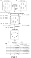
- the extraction of the score will be described with reference to Fig. 2 .
- the surface of the cut workpiece 155 is shown in the camera image as illustrated in (a) of Fig. 2 .
- a target surface of a workpiece to be obtained from cutting is shown in a model image registered in advance as illustrated in (b) of Fig. 2 .
- the shape of a part A of the cut portion (the cross-shaped convex part) shown in the camera image is distinctly different from the shape of a part B of the cut portion (the cross-shaped convex part) shown in the model image.
- the inspection device 200 compares the camera image with the model image through image processing such as pattern matching, or the like to calculate a degree of matching of the cut portions between the two images. Accordingly, a score is calculated as an index indicating a degree of matching at each set of coordinates in a camera coordinate system.
- the camera coordinate system is a coordinate system uniquely defined in the camera image.
- the inspection device 200 converts the score at each set of coordinates in the camera coordinate system into a score at each set of coordinates in the workpiece coordinate system and thereby extracts the score in the workpiece coordinate system as illustrated in (c) of Fig. 2 .
- the workpiece coordinate system is a coordinate system uniquely defined in the workpiece 155.
- the horizontal axis is defined as an X axis
- the vertical axis is defined as a Y axis.
- X1, X2, X3, ..., and Xn are determined from the left to the right of the workpiece coordinate system at equal intervals.
- Y1, Y2, Y3, ..., and Yn are determined from the top to the bottom of the workpiece coordinate system at equal intervals.
- the score calculated based on the comparison of the camera image with the model image is extracted at each set of coordinates in the workpiece coordinate system. In this example, as the score becomes lower, the degree of matching between the camera image and the model image becomes higher, and on the other hand, as the score becomes higher, the degree of matching between the camera image and the model image becomes lower.
- the score at coordinates (X1, Y1) is 0, the score at coordinates (X1, Y2) is 0, the score at coordinates (Xn, Y1) is 0, and the score at coordinates (Xn, Yn) is 0, and the camera image completely matches the model image at these coordinates.
- the score at coordinates (Xa, Ya) is 1, and the camera image almost matches the model image at the coordinates.
- the score at coordinates (Xb, Yb) is 4, the score at coordinates (Xc, Yc) is 8, and the score at coordinates (Xd, Yd) is 6, and the degrees of match of the camera image and the model image at these coordinates are low.
- the reason for this is that the shape of the part A of the cut portion shown in the camera image is distinctly different from the shape of the part B of the cut portion shown in the model image as described above.
- the inspection device 200 calculates a score exceeding a threshold value among the scores at those coordinates as an abnormal value. For example, if the threshold value of scores is set to 3, each of the score 4 at coordinates (Xb, Yb), the score 8 at coordinates (Xc, Yc), and the score 6 at coordinates (Xd, Yd) are abnormal values.
- the scores in the workpiece coordinate system extracted as described above are transmitted from the inspection device 200 to the control device 100.
- the control device 100 includes an identification unit 160 that identifies a moving part that has caused an abnormality in inspection results among the plurality of moving parts based on the inspection results of the inspection device 200 and the command values issued to the plurality of moving parts.
- the above-described scores in the workpiece coordinate system are exemplified as the inspection results.
- simulation values defining movement paths of the moving parts of each of the robots a and b may be exemplified. The simulation values are registered by the manager of the production site, or the like in advance.
- the identification unit 160 of the control device 100 compares each score in the workpiece coordinate system acquired from the inspection device 200 with the simulation values to identify a moving part that was performing machining at a position on the workpiece 155 corresponding to the sets of coordinates at which the score has an abnormal value.
- control device 100 includes a storage unit 170 that collects and stores data on a moving part that has been identified by the identification unit 160 and caused an abnormality in the inspection results.
- the control device 100 identifies a moving part that has caused an abnormality in the inspection results by comparing the scores in the workpiece coordinate system illustrated in (c) of Fig. 2 and the simulation values illustrated in (d) of Fig. 2 .
- the control device 100 may identify a moving part of the robot a among the plurality of robots a and b as being abnormal and further identify the operation period of this moving part of the robot a.
- the control device 100 identifies the period from t2 to t3 as operation periods of a moving part 1 to a moving part 6 of the robot a that have caused the abnormality as illustrated in (e) of Fig. 2 . Then, the control device 100 acquires data on the operations of the moving part 1 to the moving part 6 of the robot a in the period from t2 to t3 in each control cycle after the operation periods are identified and stores the data in a memory or the like.
- the data collected as described above is used to realize predictive maintenance. For example, when there is a sign of an abnormality in the machined workpiece product, the manager of the production site, or the like can identify a moving part that has caused an abnormality based on the collected data, without relying on his or her own experience and knowledge as far as possible. In addition, the manager or the like can perform predictive maintenance including maintenance, replacement, and the like before the facilities need to be stopped by studying the cause of the sign of the abnormality based on the collected data.
- FIG. 3 is a schematic diagram for describing an overall configuration example of the control system 1 according to the present embodiment.
- the control device 100 corresponds to an industrial controller that controls control targets such as various facilities and devices.
- the control device 100 is a type of computer that executes control arithmetic operations and is typically embodied as a programmable controller (PLC).
- PLC programmable controller
- the control device 100 is connected to field devices 500 via a field network 2.
- the control device 100 exchanges data with one or a plurality of field devices 500 via the field network 2.
- the control computational operations executed by the control device 100 includes processing of collecting data (input data) collected or generated by the field devices 500 (input processing), processing of generating data (output data) such as a command value or the like to be issued to the field device 500 (arithmetic operation processing), processing of transmitting the generated output data to the target field device 500 (output processing), and the like.
- the field network 2 preferably employs a bus or a network for performing fixed cycle communication.
- a bus or a network for performing fixed cycle communication EtherCAT (registered trademark), EtherNet/IP (registered trademark), DeviceNet (registered trademark), CompoNet (registered trademark), and the like are known.
- EtherCAT registered trademark
- EtherNet/IP registered trademark
- DeviceNet registered trademark
- CompoNet registered trademark
- EtherCAT registered trademark
- Each field device 500 can be connected to the field network 2.
- Each field device 500 includes an actuator that applies a certain physical effect to the robots, conveyors, and the like placed on the field side, an input/output device that exchanges information with the field side, and the like.
- the exchanged data is updated using a very short cycle time in an order of several hundreds of ⁇ sec to several tens of msec.
- the control device 100 controls a robot 550.
- the robot 550 corresponds to the robot a or the robot b illustrated in Fig. 1 described above.
- the robot 550 is a processing device that performs cutting in the present embodiment as described above. Specifically, the robot 550 includes an arm constituted by a first arm 551, a second arm 552, a third arm 553, and a fourth arm 554, an end effector 555 provided at the tip of the arm, and a drill 556 attached to the end effector 555.
- the first arm 551 is connected to a base 557 via a moving shaft 550_1 and moves around the axis of rotation of the moving shaft 550_1 with respect to the base 557.
- the second arm 552 is connected to the first arm 551 via a moving shaft 550_2 and moves around the axis of rotation of the moving shaft 550_2 with respect to the first arm 551.
- the third arm 553 is connected to the second arm 552 via a moving shaft 550_3 and moves around the axis of rotation of the moving shaft 550_3 with respect to the second arm 552.
- the fourth arm 554 is connected to the third arm 553 via a moving shaft 550_4 and moves around the axis of rotation of the moving shaft 550_4 with respect to the third arm 553.
- the end effector 555 is connected to the fourth arm 554 via a moving shaft 550_5 and moves around the axis of rotation of the moving shaft 550_5 with respect to the fourth arm 554.
- the drill 556 is connected to the end effector 555 via a moving shaft 550_6 and moves around the axis of rotation of the moving shaft 550_6 with respect to the end effector 555.
- each field device 500 includes a plurality of servo drivers 520_1 to 520_6 and a plurality of servo motors 522_1 to 522_6 connected to the plurality of servo drivers 520_1 to 520_6, respectively.
- the servo drivers 520_1 to 520_6 drive a corresponding servo motor among the servo motors 522_1 to 522_6 according to command values (e.g., a position command value, a speed command value, and the like) from the control device 100.
- command values e.g., a position command value, a speed command value, and the like
- the moving shaft 550_1 rotates.
- the moving shaft 550_2 rotates.
- the moving shaft 550_3 rotates.
- the moving shaft 550_4 the moving shaft 550_4 rotates.
- the moving shaft 550_5 rotates.
- the moving shaft 550_6 rotates.
- the arm constituted by the arms 551 to 554 operates within a predetermined operation range, and accordingly, the end effector 555 provided at the tip of the arm moves to a machining position of the workpiece 155. Then, when the moving shaft 550_6 rotates, the drill 556 attached to the tip of the end effector 555 rotates to cut the workpiece 155.
- the above-described moving shafts 550_1 to 550_6 and end effector 555 are an example of the "moving part.”
- the robot 550 is not limited to a device that performs cutting, and may be any machining device that performs lathe machining, milling machining, electrical discharge machining, or the like.
- the robot 550 may be an assembling device that assembles parts to the transported workpiece 155.
- the control device 100 is connected to the inspection device 200 via the field network 2.
- the inspection device 200 is connected to the camera 150 that images continuously transported workpieces 155.
- the camera 150 includes an optical system including a lens, a diaphragm, and the like, a light receiving sensor such as a charge coupled device (CCD) image sensor, a complementary metal oxide semiconductor (CMOS) image sensor, or the like, as main constituent components.
- the inspection device 200 is an image sensor that images the workpiece 155 with the camera 150 while illuminating the workpiece under control of the control device 100 in a production line for industrial products, or the like, and inspects the external appearance of the workpiece 155 using the obtained image.
- the control device 100 is also connected to another device via an upper network 6.
- an upper network 6 Ethernet (registered trademark) that is a general network protocol or EtherNet/IP (registered trademark) may be employed. More specifically, the upper network 6 may be connected to one or a plurality of server devices 300 and one or a plurality of display devices 400.
- the server device 300 is assumed as a database system, a manufacturing execution system (MES), or the like.
- the manufacturing execution system is a system that acquires information from a manufacturing device or facility to be controlled and monitors and manages the entire production, and can handle order information, quality information, and shipping information, and the like.
- the configuration is not limited thereto, and a device that provides an information-based service may be connected to the upper network 6.
- the information-based service is assumed as processing of acquiring information from the manufacturing device or facility to be controlled and performing macro or micro analysis thereon, or the like.
- a machine learning tool for performing data mining for extracting a certain trend in characteristics included in information from a manufacturing device or facility to be controlled or machine learning based on information from a facility or machine to be controlled, or the like may be assumed.
- the display device 400 receives an operation from a user and outputs a command or the like according to the user operation to the control device 100, and graphically displays the arithmetic operation result of the control device 100.
- a support device 600 can be connected to the control device 100.
- the support device 600 is a device that supports preparation required for the control device 100 to control a control target.
- the support device 600 provides a development environment of a control program 30 executed by the control device 100 (a program creation/editing tool, a parser, a compiler, or the like), a configuration environment for setting configuration information (configuration) of the control device 100 and various devices connected to the control device 100, a function of outputting the generated control program 30 to the control device 100, a function of modifying and changing the control program 30 or the like executed by the control device 100 online, and the like.
- the manager, or the like can register a simulation value defining a movement path of a moving part of the robot 550 using the support device 600.
- control device 100 the support device 600, and the display device 400 are configured as separate parts in the control system 1 illustrated in Fig. 3 , a configuration in which all or some of the functions are combined in a single device may be employed.
- FIG. 4 is a block diagram for describing a hardware configuration example of the control device 100 according to the present embodiment.
- the control device 100 is an arithmetic operation processing part that is called a CPU unit, and includes a processor 102, a chipset 104, a main memory 106, a storage 108, an upper network controller 110, an inspection device interface 112, a support device interface 117, a memory card interface 114, an internal bus controller 120, and a field network controller 130.
- the processor 102 is constituted by a central processing unit (CPU), a micro processing unit (MPU), a graphics processing unit (GPU), or the like. As the processor 102, a configuration with a plurality of cores may be employed, or a plurality of processors 102 may be disposed.
- the chipset 104 realizes overall processing of the control device 100 by controlling the processor 102 and peripheral elements.
- the main memory 106 is constituted by a volatile storage device such as a dynamic random access memory (DRAM) or a static random access memory (SRAM).
- the main memory 106 is typically designated as a data storage destination of the storage unit 170 illustrated in Fig. 1 .
- the storage 108 is constituted by a non-volatile storage device, for example, a hard disk drive (HDD), a solid state drive (SSD), or the like.
- the processor 102 reads various programs stored in the storage 108, loads and executes the programs in the main memory 106, and thereby realizes control and various types of processing in accordance with control targets.
- the storage 108 stores the control program 30 created according to a manufacturing device or facility to be controlled in addition to a system program 34 for realizing basic functions.
- the upper network controller 110 controls exchange of data with the server device 300, the display device 400, and the like via the upper network 6.
- the inspection device interface 112 controls exchange of data with the inspection device 200.
- the support device interface 117 controls exchange of data with the support device 600. Further, the support device 600 may be able to communicate with the control device 100 via a USB connection or through EtherNet communication.
- the memory card interface 114 is configured to have a memory card 116 be detachable therefrom, and can write data into the memory card 116 and read various types of data (user program, trace data, and the like) from the memory card 116.
- the internal bus controller 120 controls exchange of data with an I/O unit 122 mounted on the control device 100.
- the field network controller 130 controls exchange of data with the field devices via the field network 2.
- a configuration example in which necessary functions are provided by the processor 102 executing programs is introduced in Fig. 4
- some or all of the provided functions may be implemented using a dedicated hardware circuit (e.g., an ASIC, an FPGA, or the like).
- main units of the control device 100 may be realized using hardware following a generic architecture (e.g., an industrial PC based on a generic PC).
- a plurality of operating systems (OSs) for different uses may be executed in parallel, and at the same time, a necessary application may be executed on each OS using a virtualization technology.
- OSs operating systems
- FIG. 5 is a block diagram for describing a hardware configuration example of the inspection device 200 according to the present embodiment.
- the inspection device 200 includes a processor 210, a memory 212, a system controller 216, an input/output (I/O) controller 218, a hard disk 220, a camera interface 222, a control device interface 226, and a memory card interface 230. These units are connected so as to communicate data with each other having the system controller 216 at the center.
- I/O input/output
- the processor 210 is constituted by a central processing unit (CPU), a micro processing unit (MPU), a graphics processing unit (GPU), or the like.
- the processor 210 realizes desired arithmetic operation processing by exchanging programs (codes) with the system controller 216 and executing them in a predetermined order.
- the system controller 216 is connected to the processor 210, the memory 212, and the I/O controller 218 via buses, respectively, to perform data exchange with each of the units, and the like and control processing of the entire inspection device 200.
- the memory 212 is constituted by a volatile storage device such as a dynamic random access memory (DRAM) or a static random access memory (SRAM).
- DRAM dynamic random access memory
- SRAM static random access memory
- the memory 212 retains programs read from the hard disk 220, data of camera image acquired by the camera 150, or the like. In addition, the memory 212 retains data of the model image used in the inspection of the external appearance, or the like.
- the I/O controller 218 controls exchange of data with a recording medium connected to the control device 100 or an external apparatus. More specifically, the I/O controller 218 is connected to the hard disk 220, the camera interface 222, the control device interface 226, and the memory card interface 230.
- the hard disk 220 is a typical non-volatile magnetic storage device, and stores various set values, and the like in addition to a control program such as an algorithm executed by the processor 210.
- a control program such as an algorithm executed by the processor 210.
- control programs installed in the hard disk 220 a program executed when the camera 150 is controlled to acquire a captured image of the workpiece 155 and a program executed when the external appearance of the workpiece 155 is inspected using the acquired captured image are exemplified. These control programs are distributed in a state in which the control programs are stored in the memory card 236, or the like.
- a semiconductor storage device such as a flash memory or an optical storage device such as a digital versatile disk random access memory (DVD-RAM) may be employed.
- DVD-RAM digital versatile disk random access memory
- the camera interface 222 acquires camera images by imaging the workpiece 155 and mediates data transmission between the processor 210 and the camera 150.
- the camera interface 222 includes an image buffer 222a for temporarily accumulating data of the camera images from the camera 150.
- the control device interface 226 mediates data transmission between the processor 210 and the control device 100.
- the memory card interface 230 mediates data transmission between the processor 210 and the memory card 236 that is a recording medium.
- a program to be executed by the inspection device 200, or the like is distributed in a state in which the program is stored in the memory card 236, and the memory card interface 230 reads the program from the memory card 236.
- the memory card 236 includes a generic semiconductor storage device such as Secure Digital (SD), a magnetic recording medium such as a flexible disk, an optical recording medium such as a compact disk read only memory (CD-ROM), or the like.
- SD Secure Digital
- CD-ROM compact disk read only memory
- a program downloaded from a distribution server may be installed in the inspection device 200.
- some or all of functions provided through execution of a program may be implemented as a dedicated hardware circuit.
- Fig. 6 is a flowchart showing simulation processing executed by the control device 100 according to the present embodiment.
- the control device 100 stores a simulation value defining a movement path of a moving part of the robot 550 by executing simulation processing based on an operation of the manager, or the like.
- the control device 100 starts simulation based on an operation of the manager, or the like (S2).
- the control device 100 first sets a movement start position of a moving part when simulation starts (S4).
- the movement start position of the moving part is designated by the manager, or the like.
- the control device 100 sets the set movement start position of the moving part as a calculation start position (S6).
- the control device 100 sets a target position (S8).
- the target position of the moving part is designated by the manager, or the like.
- the control device 100 sets a movement method of the moving part and a parameter (S10).
- the movement method of the moving part and the parameter are designated by the manager, or the like.
- the control device 100 calculates a movement path between the calculation start position set in S6 and the target position set in S8 based on the movement method and the parameter set in S10 (S12).
- the control device 100 determines whether the movement path has been confirmed with an operation of the manager, or the like (S14). The control device 100 executes the processing from S8 again if the movement path has not been confirmed (NO in S14). The control device 100 converts the confirmed movement path into coordinate values in the workpiece coordinate system (S16) if the movement path has been confirmed (YES in S14). Then, the control device 100 stores the movement path that has been converted into the coordinate values in the workpiece coordinate system as simulation values (S18).
- the control device 100 sets an allowable range of the simulation values (S20). That is, the control device 100 adds a margin to the simulation values, considering that there can be a deviation in the movement path due to a change in the speed of the robot 550 or fine adjustment of a teaching point for the robot 550 to make the range covered by the robot 550.
- the allowable range of the simulation values is designated by the manager, or the like. Then, the control device 100 ends the simulation (S22), and ends the present processing.
- Fig. 7 is a flowchart showing score calculation processing executed by the inspection device 200 according to the present embodiment.
- the inspection device 200 calculates a score in the workpiece coordinate system as a result of the external appearance inspection by executing score calculation processing each time the workpiece 155 is imaged.
- the inspection device 200 acquires a camera image by imaging the cut portion of the workpiece 155 with the camera 150 (S32). The inspection device 200 compares the acquired camera image with the pre-registered model image (S34).
- the inspection device 200 calculates the score in the workpiece coordinate system based on the comparison of the camera image with the model image (S36).
- the inspection device 200 outputs the calculated score in the workpiece coordinate system to the control device 100 (S38). Then, the inspection device 200 ends the present processing.
- Fig. 8 is a flowchart showing cause location identification processing executed by the control device 100 according to the present embodiment.
- the control device 100 identifies a moving part that has caused an abnormality in the result of the external appearance inspection by executing cause location identification processing.
- the control device 100 acquires a score in the workpiece coordinate system output from the inspection device 200 (S52).
- the control device 100 compares the acquired score in the workpiece coordinate system with a simulation value (S54).
- the control device 100 identifies the robot that has machined the workpiece 155 at the location corresponding to the coordinates at which the score matches the abnormal value and the operation period of the robot (S56). For example, the control device 100 identifies the robot 550 that has caused the abnormality among the plurality of robots 550. Furthermore, the control device 100 identifies the operation period of the robot 550 that has caused the abnormality. Then, the control device 100 ends the present processing.
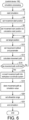
- Fig. 9 is a flowchart showing data storage processing executed by the control device 100 according to the present embodiment.
- the control device 100 determines target data to be stored by executing data storage processing.
- the control device 100 retrieves data on the robot 550 that has caused the abnormality as shown in Fig. 9 (S72). The control device 100 compares a current value of the end effector 555 included in the robot 550 that has caused the abnormality with a pre-registered ideal value (S74).
- the control device 100 determines whether the current value of the end effector 555 is abnormal based on the comparison of the current value of the end effector 555 with the ideal value (S76). If the current value of the end effector 555 is abnormal (YES in S76), the control device 100 registers the current value of the end effector 555 as target data to be stored from the next time (S78). Then, in each control cycle thereafter, the current value of the end effector 555 in the operation period identified in S56 of Fig. 8 described above is stored in the main memory 106, or the like.
- the control device 100 selects one moving shaft among all of the moving shafts 550_1 to 550_6 included in the robot 550 that has caused the abnormality (S80). The control device 100 compares the torque value of the selected one moving shaft with a pre-registered ideal value (S82).
- the control device 100 determines whether torque values of all of the moving shafts 550_1 to 550_6 have been compared with ideal values (S84). If the torque values of all of the moving shafts 550_1 to 550_6 have not been compared with the ideal values yet (NO in S84), the control device 100 executes the processing from S80 again.
- the control device 100 determines whether the torque value of any moving shaft is abnormal based on the comparison results (S86). If the torque value of any moving shaft is abnormal (YES in S86), the control device 100 registers the torque value of the moving shaft with the abnormality as target data to be stored from the next time (S88). Thus, in each control cycle thereafter, the torque value of the moving shaft in the operation period identified in S56 of Fig. 8 described above is stored in the main memory 106, or the like.
- the control device 100 determines whether another configuration included in the robot 550 that has caused the abnormality is abnormal (S90). As the other configuration, each of the arms 551 to 554, the drill 556, each of the servo motors 522_1 to 522_6, and the like are exemplified. For example, the control device 100 determines whether abrasion of a brake of each of the servo motors 522_1 to 522_6 is abnormal.
- control device 100 registers the data related to the other configuration with the abnormality as target data to be stored from the next time (S94).
- the data related to the other configuration in the operation period identified in S56 of Fig. 8 described above is stored in the main memory 106, or the like.
- control device 100 ends the present processing after S78, S88, or S94.
- the control device 100 identifies the robot 550 that has caused the abnormality based on the result of the external appearance inspection performed by the inspection device 200, and identifies the moving part that has caused the abnormality among the moving parts (e.g., the moving shafts 550_1 to 550_6 and the end effector 555) included in the identified robot 550.
- the control device 100 collects, in each control cycle from the next time, only data on the moving part that has caused the abnormality of the robot 550 that has caused the abnormality, instead of collecting data on all of the moving parts of all of the plurality of robots 550.
- resources for realizing predictive maintenance can be reduced.
- the predictive maintenance can be more efficiently realized compared to a case in which data on all of the plurality of moving parts is collected.
- the control device 100 identifies the operation period of the robot 550 that has caused the abnormality based on the result of the external appearance inspection performed by the inspection device 200.
- the control device 100 collects, in each control cycle from the next time, data only in the operation period of the robot 550 that has caused the abnormality, instead of collecting data in all of the operation periods of the robot 550 that has caused the abnormality.
- resources for realizing predictive maintenance can be reduced.
- the predictive maintenance can be more efficiently realized compared to a case in which data in all of the operation periods of the plurality of moving parts is collected.
- control device 100 identifies the robot 550 that has caused the abnormality and the moving part thereof and collects only data on the identified moving part based on the result of the external appearance inspection performed by the inspection device 200, predictive maintenance can be realized without relying on the experience and knowledge of the manager of the production site, or the like, as far as possible, and moreover, resources for the predictive maintenance can be comparatively reduced.
- the inspection device 200 converts a score in the camera coordinate system into a score in the workpiece coordinate system and then outputs the score in the workpiece coordinate system to the control device 100
- the inspection device 200 may output a score in the camera coordinate system to the control device 100 and the control device 100 may convert the score in the camera coordinate system into a score in the workpiece coordinate system in the present embodiment.
- a score at the coordinates in the workpiece coordinate system is output to the control device 100, only a score in the workpiece coordinate system that has been determined as exceeding a threshold value and as an abnormality may be output to the control device 100 in the present embodiment.
- control device 100 may collect, in each control cycle from the next time, data on all of the moving parts included in the robot 550 that has caused an abnormality
- resources for realizing predictive maintenance can of course be more reduced when collecting only data on the moving part that has caused an abnormality in each control cycle from the next time among the moving parts included in the robot 550 that has caused the abnormality, without collecting data on all of the moving parts of all of the plurality of robots 550 as in the present embodiment.
- the robot 550 may operate according to dynamically changing command values issued to the robot 550 in each control cycle based on a pre-set parameter.
- the control device 100 may use operation data on the robot 550 calculated based on the path on which the robot 550 has operated, instead of a pre-registered simulation value.
- the control device 100 may limit an operation speed or stop an operation of the robot 550 that has caused an identified abnormality and a moving part of the robot 550 based on the cause of the abnormality. For example, when a torque value of the moving shaft 550_1 among the moving shafts 550_1 to 550_6 is abnormal, the operation speed of the moving shaft 550_1 may be limited or the operation thereof may be stopped based on the torque value. Alternatively, when a current value of the end effector 555 is abnormal, the operation speed of the end effector 555 may be limited or the operation thereof may be stopped based on the current value.
- the camera 150 is a separate body from the robot 550 in the present embodiment, the camera 150 may be attached at the hand of the robot 550, for example, the end effector 555, or the like.
- the control device 100 is set to determine whether the end effector 555 is abnormal in preference to the moving shafts or other configurations as target data to be stored and sets only the end effector 555 as target data to be stored if the end effector is abnormal in the data storage processing illustrated in Fig. 9 in the present embodiment.
- the reason for this is that the end effector 555 is more likely to cause an abnormality than the moving shafts or other configurations.
- the embodiment is not limited thereto, and the control device 100 may determine whether a moving shaft or another configuration is abnormal in preference to the end effector 555, and if the moving shaft or the other configuration is abnormal, only the moving shaft or the other configuration may be set as target data to be stored.
- the control device 100 may determine whether any of the end effector 555, the moving shafts, and the other configurations is abnormal, and if any one is abnormal, data on the portion determined as being abnormal may be set as target data to be stored.
- Fig. 10 is a schematic diagram for describing an application example of a control system 1000 according to a first modification example.
- the control system 1000 includes peripheral devices that support processing of robots a and b as moving parts in addition to the robots a and b as illustrated in Fig. 10 .
- a peripheral device for example, an XY stage 810 for changing a position of a workpiece 155 as the stage moves in an X direction and a Y direction is exemplified in the example illustrated in Fig. 10 .
- the workpiece 155 that has been transported by a conveyor 800a is machined by the robots a and b while the XY stage 810 changes the position of the workpiece, and then the workpiece is transported to the camera 150 side by a conveyor 800b.
- the control system 1000 includes, in addition to the robots a and b, a control device 1100 that controls the moving parts of the robots by issuing a command value to the XY stage 810, and an inspection device 1200 that inspects the workpiece 155.
- the inspection device 1200 inspects the XY stage 810 and the external appearance of the workpiece 155 processed by the robots a and b.
- the control device 1100 identifies a moving part that has caused an abnormality in the inspection results based on the inspection results of the inspection device 1200 and the command values issued to the XY stage 810 and the robots a and b.
- the control device 1100 can predict that the robot a or b has caused the abnormality, and if the XY stage 810 is operating in the time slot, the control device can predict that the cause of the abnormality is likely to be present in the XY stage 810 as well as the robots a and b.
- control device 1100 may collect and store data on the XY stage 810 or the robots a and b that have caused the abnormality to be able to be useful for predictive maintenance.
- control device 1100 may identify a peripheral device such as the XY stage 810 as the cause of the abnormality and collect data on the peripheral device.
- peripheral device is not limited to the XY stage 810 and may be a device that supports processing of the robots a and b.
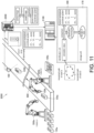
- Fig. 11 is a schematic diagram for describing an application example of a control system 2000 according to a second modification example.
- the robots a and b machine the workpiece 155 has been described in the above-described example, the present disclosure can be applied to an example in which the robots a and b assemble a finished product or parts.
- the robot a takes a part 155a and places the part on a conveyor 800. Then, the robot b takes a part 155b and attaches the part to the part 155a. In this manner, an assembly 1550 is assembled by attaching the part 155b to the part 155a by the robots a and b. The assembly 1550 is transported to the camera 150 side by the conveyor 800.
- the control system 2000 includes a control device 2100 that controls a plurality of moving parts by issuing command values to the robots a and b and an inspection device 2200 that inspects the assembly 1550.
- the inspection device 2200 inspects the external appearance of the assembly 1550 processed by the robots a and b.
- the inspection device 2200 inspects, for example, an attachment state of the part 155b or whether there is a scratch or dirt.
- the control device 2100 identifies a moving part that has caused an abnormality in the inspection results based on the inspection results of the inspection device 2200 and the command values issued to the robots a and b.
- the assembly 1550 may be inspected by the inspection device 2200 and a moving part of the robot a or b that has assembled the assembly 1550 having an abnormality may be identified based on the inspection results.
Applications Claiming Priority (2)
| Application Number | Priority Date | Filing Date | Title |
|---|---|---|---|
| JP2018147368A JP6977686B2 (ja) | 2018-08-06 | 2018-08-06 | 制御システムおよび制御装置 |
| PCT/JP2019/029848 WO2020031790A1 (ja) | 2018-08-06 | 2019-07-30 | 制御システムおよび制御装置 |
Publications (3)
| Publication Number | Publication Date |
|---|---|
| EP3835902A1 EP3835902A1 (en) | 2021-06-16 |
| EP3835902A4 EP3835902A4 (en) | 2022-04-06 |
| EP3835902B1 true EP3835902B1 (en) | 2024-02-28 |
Family
ID=69414210
Family Applications (1)
| Application Number | Title | Priority Date | Filing Date |
|---|---|---|---|
| EP19846483.6A Active EP3835902B1 (en) | 2018-08-06 | 2019-07-30 | Control system and control device |
Country Status (5)
| Country | Link |
|---|---|
| US (1) | US20210299872A1 (ja) |
| EP (1) | EP3835902B1 (ja) |
| JP (1) | JP6977686B2 (ja) |
| CN (1) | CN112424718A (ja) |
| WO (1) | WO2020031790A1 (ja) |
Families Citing this family (6)
| Publication number | Priority date | Publication date | Assignee | Title |
|---|---|---|---|---|
| JP2021174098A (ja) * | 2020-04-21 | 2021-11-01 | キヤノン株式会社 | 画像処理装置、画像処理装置の制御方法およびプログラム |
| JP7366859B2 (ja) * | 2020-08-06 | 2023-10-23 | 三菱電機株式会社 | 設備管理システムおよび設備を管理する方法 |
| JP7287528B1 (ja) | 2022-03-30 | 2023-06-06 | 凸版印刷株式会社 | 資材管理システム、資材管理方法、資材管理装置、及びプログラム |
| WO2024037769A1 (en) * | 2022-08-18 | 2024-02-22 | Carl Zeiss Ag | Method and manufacturing installation for producing a plurality of workpieces |
| EP4336291A1 (en) * | 2022-09-09 | 2024-03-13 | Carter, Amy | Systems and methods for diagnosing manufactuing systems |
| CN117583894B (zh) * | 2023-11-14 | 2024-04-30 | 佛山市高明左右铝业有限公司 | 型材自动装夹多面钻铣加工系统 |
Family Cites Families (22)
| Publication number | Priority date | Publication date | Assignee | Title |
|---|---|---|---|---|
| JP2995518B2 (ja) | 1992-08-14 | 1999-12-27 | 株式会社日立製作所 | 学習型異常診断アルゴリズム自動構築方法およびその装置 |
| JP3651295B2 (ja) * | 1999-01-18 | 2005-05-25 | 日産自動車株式会社 | 溶接ロボット特定システム |
| JP2002297221A (ja) * | 2001-03-30 | 2002-10-11 | Matsushita Electric Ind Co Ltd | 治具作業管理方法 |
| JP2006261253A (ja) * | 2005-03-15 | 2006-09-28 | Omron Corp | プロセスデータ収集装置およびモデル作成装置ならびにモデル作成システム |
| JP2007102388A (ja) * | 2005-10-03 | 2007-04-19 | Hitachi Ltd | 保守支援装置,保守支援方法,保守支援システム,制御装置および制御方法 |
| JP4620030B2 (ja) * | 2005-10-28 | 2011-01-26 | 富士通株式会社 | 設備点検支援システム、設備点検支援方法およびそのプログラム |
| JP2012052931A (ja) * | 2010-09-01 | 2012-03-15 | Sharp Corp | 検査装置、検査方法、プログラムおよび記録媒体 |
| EP2902861B1 (en) * | 2012-09-28 | 2020-11-18 | FUJI Corporation | Production line monitoring device |
| US20140114442A1 (en) * | 2012-10-22 | 2014-04-24 | The Boeing Company | Real time control system management |
| JP6264072B2 (ja) * | 2014-02-10 | 2018-01-24 | オムロン株式会社 | 品質管理装置及びその制御方法 |
| JP2015197396A (ja) * | 2014-04-02 | 2015-11-09 | 三菱電機株式会社 | 画像検査方法および画像検査装置 |
| CN107111297B (zh) * | 2014-10-31 | 2021-03-26 | 制造业大数据有限公司 | 用于由至少一台计算机数控机器加工的工件的部件分析的计算机实现方法 |
| US10564031B1 (en) * | 2015-08-24 | 2020-02-18 | X Development Llc | Methods and systems for determining errors based on detected sounds during operation of a robotic device |
| WO2017033352A1 (ja) * | 2015-08-25 | 2017-03-02 | 川崎重工業株式会社 | 産業用遠隔操作ロボットシステム |
| JP2017067633A (ja) * | 2015-09-30 | 2017-04-06 | キヤノン株式会社 | 検査装置および物品製造方法 |
| DE102015119240B3 (de) * | 2015-11-09 | 2017-03-30 | ATENSOR Engineering and Technology Systems GmbH | Automatisches detektieren und robotergestütztes bearbeiten von oberflächendefekten |
| JP6348137B2 (ja) * | 2016-03-24 | 2018-06-27 | ファナック株式会社 | 工作物の良否を判定する加工機械システム |
| JP6453805B2 (ja) * | 2016-04-25 | 2019-01-16 | ファナック株式会社 | 製品の異常に関連する変数の判定値を設定する生産システム |
| JP6919186B2 (ja) * | 2016-12-14 | 2021-08-18 | オムロン株式会社 | 制御システム、制御プログラムおよび制御方法 |
| JP7015001B2 (ja) * | 2018-03-14 | 2022-02-02 | オムロン株式会社 | 欠陥検査装置、欠陥検査方法、及びそのプログラム |
| CN110779928B (zh) * | 2019-11-19 | 2022-07-26 | 汪科道 | 缺陷检测装置及方法 |
| US11938633B2 (en) * | 2021-12-06 | 2024-03-26 | Fanuc Corporation | Autonomous robust assembly planning |
-
2018
- 2018-08-06 JP JP2018147368A patent/JP6977686B2/ja active Active
-
2019
- 2019-07-30 CN CN201980046974.4A patent/CN112424718A/zh active Pending
- 2019-07-30 EP EP19846483.6A patent/EP3835902B1/en active Active
- 2019-07-30 US US17/262,227 patent/US20210299872A1/en active Pending
- 2019-07-30 WO PCT/JP2019/029848 patent/WO2020031790A1/ja unknown
Also Published As
| Publication number | Publication date |
|---|---|
| CN112424718A (zh) | 2021-02-26 |
| EP3835902A1 (en) | 2021-06-16 |
| JP6977686B2 (ja) | 2021-12-08 |
| EP3835902A4 (en) | 2022-04-06 |
| WO2020031790A1 (ja) | 2020-02-13 |
| JP2020024484A (ja) | 2020-02-13 |
| US20210299872A1 (en) | 2021-09-30 |
Similar Documents
| Publication | Publication Date | Title |
|---|---|---|
| EP3835902B1 (en) | Control system and control device | |
| EP3385797B1 (en) | Monitoring device, monitoring system, monitoring program and recording medium | |
| CN108628263B (zh) | 控制系统、控制装置、计算机可读存储介质以及控制方法 | |
| CN108021099B (zh) | 机械学习装置以及加工时间预测装置 | |
| EP1967334B1 (en) | Detection of condition changes in an industrial robot system | |
| EP3336637A1 (en) | Control system, control program, and control method | |
| JP2019053459A (ja) | 制御装置および制御方法 | |
| KR102626984B1 (ko) | 관리 장치 및 관리 시스템 | |
| US11782431B2 (en) | Control device and non-transitory computer-readable recording medium recording program | |
| JP2019159697A (ja) | 制御システムおよび制御方法 | |
| JP2019146421A (ja) | 故障予測装置及び機械学習装置 | |
| CN104385282A (zh) | 一种视觉智能数控系统及其视觉计测方法 | |
| CN108693822A (zh) | 控制装置、存储介质、控制系统及控制方法 | |
| US11803178B2 (en) | Event estimation system and event estimation method | |
| CN112673326A (zh) | 控制装置及控制程序 | |
| US10509393B2 (en) | Control device and control method | |
| CN213634179U (zh) | 自动化装置 | |
| JP2021086218A (ja) | 協調作業システム、解析装置および解析プログラム | |
| JP2023070273A (ja) | 分析装置、分析方法およびプログラム | |
| Bojarczuk et al. | Artificial Intelligence in Predicting Abnormal States in a Robotic Production Stand | |
| WO2022181007A1 (ja) | 情報処理装置、情報処理プログラムおよび情報処理方法 | |
| US20230229137A1 (en) | Analysis device, analysis method and non-transitory computer-readable storage medium | |
| US20230315057A1 (en) | Device, recording medium and method for collecting data | |
| JPH0887316A (ja) | 制御装置 | |
| US11820007B2 (en) | Abnormality detection device and abnormality detection method |
Legal Events
| Date | Code | Title | Description |
|---|---|---|---|
| STAA | Information on the status of an ep patent application or granted ep patent |
Free format text: STATUS: THE INTERNATIONAL PUBLICATION HAS BEEN MADE |
|
| STAA | Information on the status of an ep patent application or granted ep patent |
Free format text: STATUS: THE INTERNATIONAL PUBLICATION HAS BEEN MADE |
|
| PUAI | Public reference made under article 153(3) epc to a published international application that has entered the european phase |
Free format text: ORIGINAL CODE: 0009012 |
|
| STAA | Information on the status of an ep patent application or granted ep patent |
Free format text: STATUS: REQUEST FOR EXAMINATION WAS MADE |
|
| 17P | Request for examination filed |
Effective date: 20210111 |
|
| AK | Designated contracting states |
Kind code of ref document: A1 Designated state(s): AL AT BE BG CH CY CZ DE DK EE ES FI FR GB GR HR HU IE IS IT LI LT LU LV MC MK MT NL NO PL PT RO RS SE SI SK SM TR |
|
| DAV | Request for validation of the european patent (deleted) | ||
| DAX | Request for extension of the european patent (deleted) | ||
| A4 | Supplementary search report drawn up and despatched |
Effective date: 20220309 |
|
| RIC1 | Information provided on ipc code assigned before grant |
Ipc: G05B 19/042 20060101ALI20220302BHEP Ipc: G05B 19/418 20060101ALI20220302BHEP Ipc: B25J 9/16 20060101ALI20220302BHEP Ipc: G06T 7/00 20170101ALI20220302BHEP Ipc: G05B 19/18 20060101ALI20220302BHEP Ipc: G05B 23/02 20060101AFI20220302BHEP |
|
| GRAP | Despatch of communication of intention to grant a patent |
Free format text: ORIGINAL CODE: EPIDOSNIGR1 |
|
| STAA | Information on the status of an ep patent application or granted ep patent |
Free format text: STATUS: GRANT OF PATENT IS INTENDED |
|
| INTG | Intention to grant announced |
Effective date: 20231006 |
|
| GRAS | Grant fee paid |
Free format text: ORIGINAL CODE: EPIDOSNIGR3 |
|
| GRAA | (expected) grant |
Free format text: ORIGINAL CODE: 0009210 |
|
| STAA | Information on the status of an ep patent application or granted ep patent |
Free format text: STATUS: THE PATENT HAS BEEN GRANTED |
|
| AK | Designated contracting states |
Kind code of ref document: B1 Designated state(s): AL AT BE BG CH CY CZ DE DK EE ES FI FR GB GR HR HU IE IS IT LI LT LU LV MC MK MT NL NO PL PT RO RS SE SI SK SM TR |
|
| REG | Reference to a national code |
Ref country code: GB Ref legal event code: FG4D |
|
| REG | Reference to a national code |
Ref country code: CH Ref legal event code: EP |
|
| REG | Reference to a national code |
Ref country code: DE Ref legal event code: R096 Ref document number: 602019047479 Country of ref document: DE |
|
| REG | Reference to a national code |
Ref country code: IE Ref legal event code: FG4D |