EP3832785A1 - Cooler - Google Patents
Cooler Download PDFInfo
- Publication number
- EP3832785A1 EP3832785A1 EP19841204.1A EP19841204A EP3832785A1 EP 3832785 A1 EP3832785 A1 EP 3832785A1 EP 19841204 A EP19841204 A EP 19841204A EP 3832785 A1 EP3832785 A1 EP 3832785A1
- Authority
- EP
- European Patent Office
- Prior art keywords
- upper plate
- lower plate
- pedestals
- corrugate
- fluid
- Prior art date
- Legal status (The legal status is an assumption and is not a legal conclusion. Google has not performed a legal analysis and makes no representation as to the accuracy of the status listed.)
- Granted
Links
Images






Classifications
-
- H—ELECTRICITY
- H01—ELECTRIC ELEMENTS
- H01M—PROCESSES OR MEANS, e.g. BATTERIES, FOR THE DIRECT CONVERSION OF CHEMICAL ENERGY INTO ELECTRICAL ENERGY
- H01M10/00—Secondary cells; Manufacture thereof
- H01M10/60—Heating or cooling; Temperature control
- H01M10/65—Means for temperature control structurally associated with the cells
- H01M10/655—Solid structures for heat exchange or heat conduction
- H01M10/6551—Surfaces specially adapted for heat dissipation or radiation, e.g. fins or coatings
-
- H—ELECTRICITY
- H01—ELECTRIC ELEMENTS
- H01M—PROCESSES OR MEANS, e.g. BATTERIES, FOR THE DIRECT CONVERSION OF CHEMICAL ENERGY INTO ELECTRICAL ENERGY
- H01M10/00—Secondary cells; Manufacture thereof
- H01M10/60—Heating or cooling; Temperature control
- H01M10/62—Heating or cooling; Temperature control specially adapted for specific applications
- H01M10/625—Vehicles
-
- H—ELECTRICITY
- H01—ELECTRIC ELEMENTS
- H01M—PROCESSES OR MEANS, e.g. BATTERIES, FOR THE DIRECT CONVERSION OF CHEMICAL ENERGY INTO ELECTRICAL ENERGY
- H01M10/00—Secondary cells; Manufacture thereof
- H01M10/60—Heating or cooling; Temperature control
- H01M10/65—Means for temperature control structurally associated with the cells
- H01M10/655—Solid structures for heat exchange or heat conduction
- H01M10/6556—Solid parts with flow channel passages or pipes for heat exchange
-
- H—ELECTRICITY
- H01—ELECTRIC ELEMENTS
- H01M—PROCESSES OR MEANS, e.g. BATTERIES, FOR THE DIRECT CONVERSION OF CHEMICAL ENERGY INTO ELECTRICAL ENERGY
- H01M2220/00—Batteries for particular applications
- H01M2220/20—Batteries in motive systems, e.g. vehicle, ship, plane
-
- H—ELECTRICITY
- H10—SEMICONDUCTOR DEVICES; ELECTRIC SOLID-STATE DEVICES NOT OTHERWISE PROVIDED FOR
- H10W—GENERIC PACKAGES, INTERCONNECTIONS, CONNECTORS OR OTHER CONSTRUCTIONAL DETAILS OF DEVICES COVERED BY CLASS H10
- H10W40/00—Arrangements for thermal protection or thermal control
- H10W40/20—Arrangements for cooling
- H10W40/22—Arrangements for cooling characterised by their shape, e.g. having conical or cylindrical projections
- H10W40/226—Arrangements for cooling characterised by their shape, e.g. having conical or cylindrical projections characterised by projecting parts, e.g. fins to increase surface area
-
- H—ELECTRICITY
- H10—SEMICONDUCTOR DEVICES; ELECTRIC SOLID-STATE DEVICES NOT OTHERWISE PROVIDED FOR
- H10W—GENERIC PACKAGES, INTERCONNECTIONS, CONNECTORS OR OTHER CONSTRUCTIONAL DETAILS OF DEVICES COVERED BY CLASS H10
- H10W40/00—Arrangements for thermal protection or thermal control
- H10W40/40—Arrangements for thermal protection or thermal control involving heat exchange by flowing fluids
- H10W40/47—Arrangements for thermal protection or thermal control involving heat exchange by flowing fluids by flowing liquids, e.g. forced water cooling
-
- Y—GENERAL TAGGING OF NEW TECHNOLOGICAL DEVELOPMENTS; GENERAL TAGGING OF CROSS-SECTIONAL TECHNOLOGIES SPANNING OVER SEVERAL SECTIONS OF THE IPC; TECHNICAL SUBJECTS COVERED BY FORMER USPC CROSS-REFERENCE ART COLLECTIONS [XRACs] AND DIGESTS
- Y02—TECHNOLOGIES OR APPLICATIONS FOR MITIGATION OR ADAPTATION AGAINST CLIMATE CHANGE
- Y02E—REDUCTION OF GREENHOUSE GAS [GHG] EMISSIONS, RELATED TO ENERGY GENERATION, TRANSMISSION OR DISTRIBUTION
- Y02E60/00—Enabling technologies; Technologies with a potential or indirect contribution to GHG emissions mitigation
- Y02E60/10—Energy storage using batteries
Definitions
- the present invention relates to a cooling device for cooling a semiconductor device, a power device such as a battery and an inverter arranged in an electric vehicle or a hybrid vehicle, and so on.
- a battery is adopted as a power source for a motor that propels the vehicle.
- cooling device of this kind in which a coolant channel is provided inside a cooling plate (cooling device) arranged at the bottom of the battery (for example, see Japanese Patent laid-open No. 2010-50000 ).
- the cooling device of this kind is cooled by vaporization heat of coolant supplied to the coolant channel, and the battery is cooled by transferring heat of the battery to the cooling device thus cooled.
- radiator fins are attached to aluminum flat pipe having a plurality of coolant channels extending parallel to one another.
- the coolant is supplied to the cooling device arranged at a bottom of the battery thereby cooling the battery in which a plurality of battery cells are connected to one another.
- the power device such as the inverter, the semiconductor device etc. other than the battery also may not be cooled homogeneously and efficiently due to a variation in surface temperature (temperature deviation).
- the present invention has been conceived noting the foregoing technical problems, and it is therefore an object of the present invention to provide a cooling device that cools a heating element such as a battery homogeneously and efficiently, by suppressing a temperature variation on a surface of the cooling device while suppressing an increase in a temperature variation in the heating element.
- a cooling device comprising: an upper plate serving as a heat receiving surface; a lower plate arranged parallel to the upper plate across a fluid passage; and a corrugate fin interposed between the upper plate and the lower plate.
- a plurality of the corrugate fins are arranged perpendicular to the fluid passage at predetermined intervals in a flowing direction of a fluid, and both side edges of each of the corrugate fins in the flowing direction of the fluid are supported by stoppers protruding from any one of the upper plate and the lower plate.
- the upper plate and the lower plate are joined to each other through pedestals each of which bulges from any one of the upper plate and the lower plate to be fixed to the other one of the upper plate and the lower plate, and a peripheral edge of the upper plate and a peripheral edge of the lower plate are joined to each other.
- positions of the corrugate fins may be fixed by the stoppers protruding from any one of the upper plate and the lower plate, at sites to which heat of a heat generating element such as a battery is transmitted.
- arrays of the pedestals may be formed in a staggered manner at predetermined intervals in a direction perpendicular to the flowing direction of the fluid across the corrugate fins, and the stoppers may be spaced at sites adjacent to the pedestals.
- the pedestal may be shaped into a substantially circular shape viewed from the top.
- one end of the stopper may be situated on a virtual line drawn perpendicular to the corrugate fin from an intersection between: an outer circumference of one of the pedestals formed on one side of the corrugate fin; and a virtual line drawn from a center of said one of the pedestals at 45 degrees with respect to the corrugate fin.
- stopper may be situated on a virtual line drawn perpendicular to the corrugate fin from an intersection between: an outer circumference of another one of the pedestals formed on the other side of the corrugate fin; and a virtual line drawn from a center of said another one of the pedestals at 45 degrees with respect to the corrugate fin.
- the fluid flowing into the corrugate fin from upstream side may be divided by spaces between the stoppers thereby allowing the fluid to flow through the corrugate fin homogeneously. That is, given that the stoppers are not available, the fluid is not allowed to flow smoothly from upstream to downstream of the pedestal, but allowed to flow smoothly trough a section where the pedestal is not formed. Since the stoppers fixing the positions of the corrugate fins are formed at sites to which the flow of the fluid is oriented, the fluid is allowed to flow homogeneously through the cooling device entirely.
- connecting holes formed on both ends of the fluid passage may serve not only as an inlet hole but also as an outlet hole of the fluid. For this reason, flexibility of installation of the cooling device may be enhanced.
- the pedestal may be shaped into a substantially circular shape viewed from the top.
- one end of the stopper may be situated on a virtual line drawn perpendicular to the corrugate fin from an intersection between: an outer circumference of one of the pedestals formed on one side of the corrugate fin; and a virtual line drawn from a center of said one of the pedestals at 45 degrees with respect to the corrugate fin.
- other end of the stopper may be situated on a virtual line drawn perpendicular to the corrugate fin from an intersection between: an outer circumference of another one of the pedestals formed on the other side of the corrugate fin; and a virtual line drawn from a center of said another one of the pedestals at 45 degrees with respect to the corrugate fin.
- the fluid flowing around one of the pedestals is allowed to flow smoothly into the space between the stoppers formed downstream of said one of the pedestals, while being divided homogeneously by the spaces between the stoppers.
- the fluid flowing though the corrugate fin is allowed to flow out of the corrugate fin smoothly toward both sides of another one of the pedestals situated downstream of the corrugate fin while being divided homogeneously by the spaces between the stoppers.
- stoppers may be formed integrally with any one of the upper plate and the lower plate.
- the stoppers for positioning the corrugate fins may be formed easily.
- the cooling device 1 comprises: an upper plate 10 serving as a heat receiving surface arranged underneath a bottom of the battery B; a lower plate 20 arranged parallel to the upper plate 10 across a fluid passage 2; and a plurality of corrugate fins 30 interposed between the upper plate 10 and the lower plate 20.
- the battery B is adapted as a power source of a motor to propel the vehicle, and in the battery B, a plurality of battery cells (not shown) are connected to one another.
- a fluid inlet pipe 3 and a fluid outlet pipe 4 are communicated to the fluid passage 2 at each end of the cooling device 1.
- the corrugate fins 30 are arranged in a direction perpendicular to a direction of the fluid passage 2 to flow a fluid at predetermined intervals underneath the battery cells (not shown), and both side edges of each of the corrugate fins 30 in the flowing direction of the fluid are supported by stoppers 11 protruding from the upper plate 10.
- the upper plate 10 and the lower plate 20 are joined to each other through pedestals 21 each of which bulges from the lower plate 20, and a peripheral edge of the upper plate 10 and a peripheral edge of the lower plate 20 are joined to each other.
- the upper plate 10 is formed of a substantially rectangular aluminum plate material. As illustrated in Figs. 2 and 5 , a plurality of arrays of the stoppers 11 protrude from a lower surface of the upper plate 10 at predetermined intervals in the flowing direction of the fluid, so as to support the side edges of each of the corrugate fins 30 in a width (lateral) direction.
- the stoppers 11 are formed integrally with the upper plate 10 by a press working method (cf., Fig. 5(b) ).
- the stoppers 11 are spaced at sites adjacent to the pedestals 21 each of which is shaped into a circular shape viewed from the top.
- a virtual line Lb is drawn perpendicular to the corrugate fin 30 from an intersection between: an outer circumference of one of the pedestals 21 formed on one side of the corrugate fin 30; and a virtual line La drawn from a center of said one of the pedestals 21 at 45 degrees with respect to the corrugate fin 30.
- a virtual line Ld is drawn perpendicular to the corrugate fin 30 from an intersection between: an outer circumference of another one of the pedestals 21 formed on the other side of the corrugate fin 30; and a virtual line Lc drawn from a center of said another one of the pedestals 21 at 45 degrees with respect to the corrugate fin 30.
- one end is situated on the virtual line Lb, and the other end is situated on the virtual line Ld.
- each end of said one of the stoppers 11 is situated on the virtual line Lb and the virtual line Ld, respectively.
- the virtual line Lb is drawn perpendicular to the corrugate fin 30 from the intersection between: the outer circumference of the pedestal 21 formed on one side of the corrugate fin 30; and the virtual line La drawn from the center of said pedestal 21 at 45 degrees with respect to the corrugate fin 30.
- the virtual line Ld is drawn perpendicular to the corrugate fin 30 from the intersection between: the outer circumference of the pedestal 21 formed on the other side of the corrugate fin 30; and the virtual line Lc drawn from the center of said pedestal 21 at 45 degrees with respect to the corrugate fin 30. Therefore, as illustrated in Fig.
- a fluid 5 flowing around said one of the pedestals 21 is allowed to flow smoothly into the corrugate fin 30 from the space between the stoppers 11 formed downstream of said one of the pedestals 21, and to flow out of the corrugate fin 30 smoothly toward both sides of said another one of the pedestals 21.
- Connecting holes 12a and 12b are formed on each end of the upper plate 10 in a longitudinal direction as a flowing direction of the fluid 5, and for example, the fluid inlet pipe 3 and the fluid outlet pipe 4 are connected to the connecting hole 12a and the connecting hole 12b, respectively.
- small holes 13 are formed on the upper plate 10 at sites above a center of each of the pedestals 21 to fix the cooling device 1 to the vehicle.
- a thickness of the upper plate 10 is 3 mm
- a vertical length of each of the stoppers 11 is 1 mm.
- those dimensions should not be limited to the above-mentioned values.
- the lower plate 20 is made of aluminum material. As illustrated in Fig. 6 , the lower plate 20 is shaped into a flat plate shape, and an outward flange 22 is formed around the peripheral edge of the lower plate 20. On the lower plate 20, a plurality of arrays of the pedestals 21 are formed in a staggered manner, at predetermined intervals in a direction perpendicular to the flowing direction of the fluid 5 across the corrugate fins 30 (specifically, sites on which the corrugate fins 30 are disposed).
- the pedestals 21 are formed by pressing a bottom of the lower plate 20 so that each of the pedestals 21 are shaped into a substantially circular shape viewed from the top.
- An upper flat portion 21a of each of the pedestals 21 is individually aligned with the flange 22 to be contacted to a lower surface of the upper plate 10, and a round hole 21b is formed on a center of the upper flat portion 21a of each of the pedestals 21 to fix the cooling device 1 to the vehicle.
- a thickness of the lower plate 20 is 1 mm, and a height of each of the pedestals 21 is 3 mm.
- those dimensions should not be limited to the above-mentioned values.
- the corrugate fins 30 are formed of aluminum material, and as illustrated in Fig. 7 , each of the corrugate fins 30 is individually shaped into a wavy shape in which an upper flat portions 31 and lower flat portions 32 are formed alternately. According to the embodiment, a thickness of each of the corrugate fins 30 is 0.3 mm, each clearance (i.e., a pitch P between the upper flat portion 31 and the lower flat portions 32) is 1.5 mm, and a height is 3 mm. However, those dimensions should not be limited to the above-mentioned values.
- Each of the corrugate fins 30 is individually positioned between the upper plate 10 and the lower plate 20, by a pair of arrays of the stoppers 11 projecting from the upper plate 10 to support both long sides of the corrugate fin 30 in the width direction.
- the upper flat portions 31 are contacted to the lower surface of the upper plate 10, and the lower flat portions 32 are contacted to an upper surface of the lower plate 20.
- the upper plate 10, the corrugate fins 30, and the lower plate 20 are brazed to one another. Specifically, the corrugate fins 30 are individually brazed not only to the upper plate 10 but also to the lower plate 20.
- the pedestals 21 bulging from the lower plate 20 are brazed to the lower surface of the upper plate 10, and the flange 22 of the lower plate 20 is brazed to the peripheral edge of the upper plate 10.
- the corrugate fins 30 may be brazed to the upper plate 10 and the lower plate 20 using a brazing sheet in which a surface material layer is overlapped onto a core material layer, or applying brazing material to e.g., the corrugate fins 30.
- the stoppers 11 project from the lower surface of the upper plate 10 in the foregoing description, the stoppers 11 may also be projected from the upper surface of the lower plate 20.
- the pedestals 21 may also be formed by pressing the upper plate 10 downwardly to be contacted to the upper surface of the lower plate 20 as long as a heat receiving area of the upper plate 10 is ensured.
- positions of the corrugate fins 30 may be fixed to a heat generating region of the battery B by the stoppers 11 projecting from the upper plate 10 or the lower plate 20. Therefore, the temperature variations in the battery B and the surface of the cooling device 1 may be suppressed so that the battery B is cooled homogeneously and efficiently.
- the corrugate fins 30 may be attached to the upper plate 10 and the lower plate 20 easily and certainly.
- one end is situated on the virtual line Lb drawn perpendicular to the corrugate fin 30 from the intersection between: the outer circumference of one of the pedestals 21 formed on one side of the corrugate fin 30; and the virtual line La drawn from the center of said one of the pedestals 21 at 45 degrees with respect to the corrugate fin 30.
- the other end of said stopper 11 is situated on the virtual line Ld drawn perpendicular to the corrugate fin 30 from the intersection between: the outer circumference of another one of the pedestals 21 formed on the other side of the corrugate fin 30; and the virtual line Lc drawn from the center of said another one of the pedestals 21 at 45 degrees with respect to the corrugate fin 30.
- the fluid 5 flowing around said one of the pedestals 21 is allowed to flow smoothly into the corrugate fin 30 from the space between the stoppers 11 formed downstream of said one of the pedestals 21, while being divided homogeneously by the spaces between the stoppers 11 of the array of upstream of the corrugate fin 30.
- the fluid 5 flowing though the corrugate fin 30 is allowed to flow out of the corrugate fin 30 smoothly toward both sides of said another one of the pedestals 21 situated downstream of the corrugate fin 30 while being divided homogeneously by the spaces between the stoppers 11 of the array of downstream of the corrugate fin 30. Consequently, the battery B can be cooled homogeneously and efficiently.
- the connecting holes 12a and 12b may serve not only as an inlet hole but also as an outlet hole of the fluid 5. For this reason, flexibility of installation of the cooling device 1 may be enhanced.
- stoppers 11 for positioning the corrugate fins 30 are formed integrally, number of parts may be reduced and the cooling device 1 may be assembled easily.
- the cooling device according to the present invention is adapted to remove the heat generated by the battery B serving as the power source of the motor for propelling the vehicle.
- application of the cooling device according to the present invention should not limited to the foregoing embodiment, and for example, the cooling device according to the present invention may also be adapted to cool a power device such as an inverter or a semiconductor element.
- Thickness 0.3 mm
- Clearance pitch between the upper flat portion and the lower flat portions
- Length 100 mm.
- Amount of heat generation 360 W ⁇ 2.
- the cooling device was thermally insulated entirely therearound, and the comparative result was analyzed on the assumption that the heat generating area was cooled only by a heat exchange between the corrugate fin and the fluid.
- the variations in the surface temperature was analyzed using ANSYS Icepak R18.1.
- a pressure loss in the cooling device having the stoppers were slightly increased according to the Examples 1 and 2, compared to those of the cooling device without having the stoppers according to Comparative Examples 1 and 2.
- a variation in the surface temperature (temperature deviation) according to the Example 1 was 6.01 degrees C
- a variation in the surface temperature (temperature deviation) according to the Comparative Example 1 was 6.22 degrees C
- a variation in the surface temperature (temperature deviation) according to the Example 2 was 5.90 degrees C
- a variation in the surface temperature (temperature deviation) according to the Comparative Example 2 was 6.11 degrees C.
Landscapes
- Engineering & Computer Science (AREA)
- Manufacturing & Machinery (AREA)
- Chemical & Material Sciences (AREA)
- Chemical Kinetics & Catalysis (AREA)
- Electrochemistry (AREA)
- General Chemical & Material Sciences (AREA)
- Secondary Cells (AREA)
- Cooling Or The Like Of Electrical Apparatus (AREA)
- Cooling Or The Like Of Semiconductors Or Solid State Devices (AREA)
Abstract
Description
- The present invention relates to a cooling device for cooling a semiconductor device, a power device such as a battery and an inverter arranged in an electric vehicle or a hybrid vehicle, and so on.
- Generally, in vehicles such as electric vehicles and hybrid vehicles, a battery is adopted as a power source for a motor that propels the vehicle.
- In order to operate the motor to launch and accelerate the vehicle, and to generate a brake force to stop the vehicle abruptly, a battery having a large capacity is employed.
- For these purposes, it is necessary to compulsory cool the battery using a cooling device, so as to prevent a reduction in performance of the battery due to temperature rise.
- In the prior art, there is known a cooling device of this kind in which a coolant channel is provided inside a cooling plate (cooling device) arranged at the bottom of the battery (for example, see Japanese Patent laid-open No.
2010-50000 - According to one aspect of Japanese Patent laid-open No.
2010-50000 - In the cooling device taught by Japanese Patent laid-open No.
2010-50000 - However, since a thermal boundary layer is created in each clearance between the battery cells due to a temperature difference, a variation in temperature (temperature deviation) is caused on a surface of the cooling device. For this reason, the battery may not be cooled homogeneously and efficiently.
- Likewise, for example, the power device such as the inverter, the semiconductor device etc. other than the battery also may not be cooled homogeneously and efficiently due to a variation in surface temperature (temperature deviation).
- The present invention has been conceived noting the foregoing technical problems, and it is therefore an object of the present invention to provide a cooling device that cools a heating element such as a battery homogeneously and efficiently, by suppressing a temperature variation on a surface of the cooling device while suppressing an increase in a temperature variation in the heating element.
- According to the present invention, there is provided a cooling device comprising: an upper plate serving as a heat receiving surface; a lower plate arranged parallel to the upper plate across a fluid passage; and a corrugate fin interposed between the upper plate and the lower plate. In order to achieve the above-explained objective, according to the present invention, a plurality of the corrugate fins are arranged perpendicular to the fluid passage at predetermined intervals in a flowing direction of a fluid, and both side edges of each of the corrugate fins in the flowing direction of the fluid are supported by stoppers protruding from any one of the upper plate and the lower plate. In addition, the upper plate and the lower plate are joined to each other through pedestals each of which bulges from any one of the upper plate and the lower plate to be fixed to the other one of the upper plate and the lower plate, and a peripheral edge of the upper plate and a peripheral edge of the lower plate are joined to each other.
- According to the above-explained configuration, therefore, positions of the corrugate fins may be fixed by the stoppers protruding from any one of the upper plate and the lower plate, at sites to which heat of a heat generating element such as a battery is transmitted.
- According to the present invention, arrays of the pedestals may be formed in a staggered manner at predetermined intervals in a direction perpendicular to the flowing direction of the fluid across the corrugate fins, and the stoppers may be spaced at sites adjacent to the pedestals.
- In this case, the pedestal may be shaped into a substantially circular shape viewed from the top. In addition, one end of the stopper may be situated on a virtual line drawn perpendicular to the corrugate fin from an intersection between: an outer circumference of one of the pedestals formed on one side of the corrugate fin; and a virtual line drawn from a center of said one of the pedestals at 45 degrees with respect to the corrugate fin. On the other hand, other end of the stopper may be situated on a virtual line drawn perpendicular to the corrugate fin from an intersection between: an outer circumference of another one of the pedestals formed on the other side of the corrugate fin; and a virtual line drawn from a center of said another one of the pedestals at 45 degrees with respect to the corrugate fin.
- According to the above-explained configuration, therefore, the fluid flowing into the corrugate fin from upstream side may be divided by spaces between the stoppers thereby allowing the fluid to flow through the corrugate fin homogeneously. That is, given that the stoppers are not available, the fluid is not allowed to flow smoothly from upstream to downstream of the pedestal, but allowed to flow smoothly trough a section where the pedestal is not formed. Since the stoppers fixing the positions of the corrugate fins are formed at sites to which the flow of the fluid is oriented, the fluid is allowed to flow homogeneously through the cooling device entirely.
- In addition, connecting holes formed on both ends of the fluid passage may serve not only as an inlet hole but also as an outlet hole of the fluid. For this reason, flexibility of installation of the cooling device may be enhanced.
- As described, the pedestal may be shaped into a substantially circular shape viewed from the top. In addition, one end of the stopper may be situated on a virtual line drawn perpendicular to the corrugate fin from an intersection between: an outer circumference of one of the pedestals formed on one side of the corrugate fin; and a virtual line drawn from a center of said one of the pedestals at 45 degrees with respect to the corrugate fin. On the other hand, other end of the stopper may be situated on a virtual line drawn perpendicular to the corrugate fin from an intersection between: an outer circumference of another one of the pedestals formed on the other side of the corrugate fin; and a virtual line drawn from a center of said another one of the pedestals at 45 degrees with respect to the corrugate fin. Therefore, the fluid flowing around one of the pedestals is allowed to flow smoothly into the space between the stoppers formed downstream of said one of the pedestals, while being divided homogeneously by the spaces between the stoppers. In addition, the fluid flowing though the corrugate fin is allowed to flow out of the corrugate fin smoothly toward both sides of another one of the pedestals situated downstream of the corrugate fin while being divided homogeneously by the spaces between the stoppers.
- In addition, the stoppers may be formed integrally with any one of the upper plate and the lower plate.
- According to the above-explained configuration, therefore, the stoppers for positioning the corrugate fins may be formed easily.
- Since the present invention is configured as has been described, the following advantages may be achieved.
- (1) According to
claim 1 of the present invention, positions of the corrugate fins may be fixed to a heat generating region of the heat generating element such as a battery by the stoppers projecting from the upper plate or the lower plate. Therefore, temperature variations in the heat generating element such as a battery and the surface of the cooling device may be suppressed so that the heat generating element may be cooled homogeneously and efficiently. - (2) According to
claim 2 of the present invention, the fluid flowing into the corrugate fin from upstream side may be divided by spaces between the stoppers thereby allowing the fluid to flow through the corrugate fin homogeneously. Therefore, in addition to the advantage (1), turbulence of the flow of the fluid may be suppressed thereby cooling the heat generating element such as a battery homogeneously and efficiently.
In addition, the connecting holes formed on both ends of the fluid passage may serve not only as an inlet hole but also as an outlet hole of the fluid. Therefore, flexibility of installation of the cooling device may be enhanced. - (3) According to claim 3 of the present invention, the fluid flowing around one of the pedestals is allowed to flow smoothly into the space between the stoppers formed downstream of said one of the pedestals, and to further flow out of the corrugate fin smoothly toward both sides of another one of the pedestals situated downstream of the corrugate fin while being divided homogeneously by the spaces between the stoppers. Therefore, in addition to the advantages (1) and (2), the flow of the fluid may be further smoothened thereby cooling the heat generating element such as a battery homogeneously and efficiently.
- (4) According to
claim 4 of the present invention, the stoppers for positioning the corrugate fins may be formed easily. Therefore, in addition to the advantages (1), (2), and (3), number of parts may be reduced and the cooling device may be assembled easily. -
- [
Fig. 1 ] (a) is a plane view partially showing the cooling device according to the present invention, and (b) is a partially omitted enlarged side view showing the cooling device. - [
Fig. 2 ] (a) is an enlarged cross-sectional view along the I-I line drawn inFig. 1(a), and (b) is an enlarged cross-sectional view along the II-II line drawn inFig. 1(b) . - [
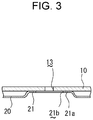
Fig. 3 ] is an enlarged cross-sectional view along the III-III line drawn inFig. 1(a) . - [
Fig. 4 ] is an enlarged plane view showing the section IV shown inFig. 1(a) . - [
Fig. 4A ] is a schematic plane view showing a flow of fluid. - [
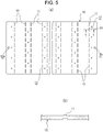
Fig. 5 ] (a) is a bottom view showing an upper plate according to the present invention, and (b) is an enlarged cross-sectional view along the V-V line drawn inFig. 5(a) . - [
Fig. 6 ] (a) is a plane view showing a lower plate according to the present invention, and (b) is an enlarged cross-sectional view along the VI-VI line drawn inFig. 6(a) . - [
Fig. 7 ] (a) is a plane view showing a corrugate fin according to the present invention, (b) is a partially omitted enlarged side view showing the corrugate fin shown inFig. 7(a), and (c) is an enlarged view showing the section VII shown inFig. 7(b) . - Now, embodiments of the cooling device according to the present invention will be described in detail with reference to the accompanying drawings. Hereinafter, an example of employing the cooling device to cool a heated battery mounted on a vehicle will be explained.
- As illustrated in
Figs. 1 and2 , thecooling device 1 according to the present invention comprises: anupper plate 10 serving as a heat receiving surface arranged underneath a bottom of the battery B; alower plate 20 arranged parallel to theupper plate 10 across afluid passage 2; and a plurality ofcorrugate fins 30 interposed between theupper plate 10 and thelower plate 20. For example, the battery B is adapted as a power source of a motor to propel the vehicle, and in the battery B, a plurality of battery cells (not shown) are connected to one another. A fluid inlet pipe 3 and afluid outlet pipe 4 are communicated to thefluid passage 2 at each end of thecooling device 1. - Specifically, the
corrugate fins 30 are arranged in a direction perpendicular to a direction of thefluid passage 2 to flow a fluid at predetermined intervals underneath the battery cells (not shown), and both side edges of each of thecorrugate fins 30 in the flowing direction of the fluid are supported bystoppers 11 protruding from theupper plate 10. - In addition, the
upper plate 10 and thelower plate 20 are joined to each other throughpedestals 21 each of which bulges from thelower plate 20, and a peripheral edge of theupper plate 10 and a peripheral edge of thelower plate 20 are joined to each other. - The
upper plate 10 is formed of a substantially rectangular aluminum plate material. As illustrated inFigs. 2 and5 , a plurality of arrays of thestoppers 11 protrude from a lower surface of theupper plate 10 at predetermined intervals in the flowing direction of the fluid, so as to support the side edges of each of thecorrugate fins 30 in a width (lateral) direction. Thestoppers 11 are formed integrally with theupper plate 10 by a press working method (cf.,Fig. 5(b) ). - Specifically, in the array of the
stoppers 11, thestoppers 11 are spaced at sites adjacent to thepedestals 21 each of which is shaped into a circular shape viewed from the top. InFig. 4 , a virtual line Lb is drawn perpendicular to thecorrugate fin 30 from an intersection between: an outer circumference of one of thepedestals 21 formed on one side of thecorrugate fin 30; and a virtual line La drawn from a center of said one of thepedestals 21 at 45 degrees with respect to thecorrugate fin 30. Likewise, a virtual line Ld is drawn perpendicular to thecorrugate fin 30 from an intersection between: an outer circumference of another one of thepedestals 21 formed on the other side of thecorrugate fin 30; and a virtual line Lc drawn from a center of said another one of thepedestals 21 at 45 degrees with respect to thecorrugate fin 30. In one of thestoppers 11 in the array, one end is situated on the virtual line Lb, and the other end is situated on the virtual line Ld. - Thus, each end of said one of the
stoppers 11 is situated on the virtual line Lb and the virtual line Ld, respectively. As described, the virtual line Lb is drawn perpendicular to thecorrugate fin 30 from the intersection between: the outer circumference of thepedestal 21 formed on one side of thecorrugate fin 30; and the virtual line La drawn from the center of saidpedestal 21 at 45 degrees with respect to thecorrugate fin 30. On the other hand, the virtual line Ld is drawn perpendicular to thecorrugate fin 30 from the intersection between: the outer circumference of thepedestal 21 formed on the other side of thecorrugate fin 30; and the virtual line Lc drawn from the center of saidpedestal 21 at 45 degrees with respect to thecorrugate fin 30. Therefore, as illustrated inFig. 4A , afluid 5 flowing around said one of thepedestals 21 is allowed to flow smoothly into thecorrugate fin 30 from the space between thestoppers 11 formed downstream of said one of thepedestals 21, and to flow out of thecorrugate fin 30 smoothly toward both sides of said another one of thepedestals 21. - Connecting
holes upper plate 10 in a longitudinal direction as a flowing direction of thefluid 5, and for example, the fluid inlet pipe 3 and thefluid outlet pipe 4 are connected to the connectinghole 12a and the connectinghole 12b, respectively. In addition,small holes 13 are formed on theupper plate 10 at sites above a center of each of thepedestals 21 to fix thecooling device 1 to the vehicle. According to the embodiment, a thickness of theupper plate 10 is 3 mm, and a vertical length of each of thestoppers 11 is 1 mm. However, those dimensions should not be limited to the above-mentioned values. - The
lower plate 20 is made of aluminum material. As illustrated inFig. 6 , thelower plate 20 is shaped into a flat plate shape, and anoutward flange 22 is formed around the peripheral edge of thelower plate 20. On thelower plate 20, a plurality of arrays of thepedestals 21 are formed in a staggered manner, at predetermined intervals in a direction perpendicular to the flowing direction of thefluid 5 across the corrugate fins 30 (specifically, sites on which thecorrugate fins 30 are disposed). - The
pedestals 21 are formed by pressing a bottom of thelower plate 20 so that each of thepedestals 21 are shaped into a substantially circular shape viewed from the top. An upperflat portion 21a of each of thepedestals 21 is individually aligned with theflange 22 to be contacted to a lower surface of theupper plate 10, and around hole 21b is formed on a center of the upperflat portion 21a of each of thepedestals 21 to fix thecooling device 1 to the vehicle. - According to the embodiment, a thickness of the
lower plate 20 is 1 mm, and a height of each of thepedestals 21 is 3 mm. However, those dimensions should not be limited to the above-mentioned values. - The
corrugate fins 30 are formed of aluminum material, and as illustrated inFig. 7 , each of thecorrugate fins 30 is individually shaped into a wavy shape in which an upperflat portions 31 and lowerflat portions 32 are formed alternately. According to the embodiment, a thickness of each of thecorrugate fins 30 is 0.3 mm, each clearance (i.e., a pitch P between the upperflat portion 31 and the lower flat portions 32) is 1.5 mm, and a height is 3 mm. However, those dimensions should not be limited to the above-mentioned values. - Each of the
corrugate fins 30 is individually positioned between theupper plate 10 and thelower plate 20, by a pair of arrays of thestoppers 11 projecting from theupper plate 10 to support both long sides of thecorrugate fin 30 in the width direction. The upperflat portions 31 are contacted to the lower surface of theupper plate 10, and the lowerflat portions 32 are contacted to an upper surface of thelower plate 20. - The
upper plate 10, thecorrugate fins 30, and thelower plate 20 are brazed to one another. Specifically, thecorrugate fins 30 are individually brazed not only to theupper plate 10 but also to thelower plate 20. Thepedestals 21 bulging from thelower plate 20 are brazed to the lower surface of theupper plate 10, and theflange 22 of thelower plate 20 is brazed to the peripheral edge of theupper plate 10. - For example, the
corrugate fins 30 may be brazed to theupper plate 10 and thelower plate 20 using a brazing sheet in which a surface material layer is overlapped onto a core material layer, or applying brazing material to e.g., thecorrugate fins 30. - Although the
stoppers 11 project from the lower surface of theupper plate 10 in the foregoing description, thestoppers 11 may also be projected from the upper surface of thelower plate 20. In addition, thepedestals 21 may also be formed by pressing theupper plate 10 downwardly to be contacted to the upper surface of thelower plate 20 as long as a heat receiving area of theupper plate 10 is ensured. - As described, in the
cooling device 1 according to the embodiment, positions of thecorrugate fins 30 may be fixed to a heat generating region of the battery B by thestoppers 11 projecting from theupper plate 10 or thelower plate 20. Therefore, the temperature variations in the battery B and the surface of thecooling device 1 may be suppressed so that the battery B is cooled homogeneously and efficiently. - In addition, since the positions of the
corrugate fins 30 are fixed by thestoppers 11, thecorrugate fins 30 may be attached to theupper plate 10 and thelower plate 20 easily and certainly. - As also described, in one of the
stoppers 11 in the array, one end is situated on the virtual line Lb drawn perpendicular to thecorrugate fin 30 from the intersection between: the outer circumference of one of thepedestals 21 formed on one side of thecorrugate fin 30; and the virtual line La drawn from the center of said one of thepedestals 21 at 45 degrees with respect to thecorrugate fin 30. On the other hand, the other end of saidstopper 11 is situated on the virtual line Ld drawn perpendicular to thecorrugate fin 30 from the intersection between: the outer circumference of another one of thepedestals 21 formed on the other side of thecorrugate fin 30; and the virtual line Lc drawn from the center of said another one of thepedestals 21 at 45 degrees with respect to thecorrugate fin 30. Therefore, as illustrated inFig. 4A , thefluid 5 flowing around said one of thepedestals 21 is allowed to flow smoothly into thecorrugate fin 30 from the space between thestoppers 11 formed downstream of said one of thepedestals 21, while being divided homogeneously by the spaces between thestoppers 11 of the array of upstream of thecorrugate fin 30. Thefluid 5 flowing though thecorrugate fin 30 is allowed to flow out of thecorrugate fin 30 smoothly toward both sides of said another one of thepedestals 21 situated downstream of thecorrugate fin 30 while being divided homogeneously by the spaces between thestoppers 11 of the array of downstream of thecorrugate fin 30. Consequently, the battery B can be cooled homogeneously and efficiently. - As also described, since the arrays of the
pedestals 21 are arranged in the staggered manner, the connectingholes fluid 5. For this reason, flexibility of installation of thecooling device 1 may be enhanced. - In addition, since the
stoppers 11 for positioning thecorrugate fins 30 are formed integrally, number of parts may be reduced and thecooling device 1 may be assembled easily. - In the embodiment thus has been described, the cooling device according to the present invention is adapted to remove the heat generated by the battery B serving as the power source of the motor for propelling the vehicle. However, application of the cooling device according to the present invention should not limited to the foregoing embodiment, and for example, the cooling device according to the present invention may also be adapted to cool a power device such as an inverter or a semiconductor element.
- Here will be described a comparative result between a variation in a surface temperature of the cooling device according to the present invention (Examples 1, 2) and a variation in a surface temperature of a cooling device without having the stoppers 11 (Comparative examples 1, 2).
- Thickness: 0.3 mm, Clearance (pitch between the upper flat portion and the lower flat portions): 1.5 mm, Length: 100 mm.
- Vertical length: 1 mm, Width: 2 mm.
- Amount of heat generation: 360 W▪2.
-
- ▪ Density: 1038 kg/m3.
- ▪ Viscosity: 0.00128 Pa▪s
- ▪ Specific heat: 3482 J/ (kgK).
- ▪ Heat conductivity: 0.424 W/(mK).
- The cooling device was thermally insulated entirely therearound, and the comparative result was analyzed on the assumption that the heat generating area was cooled only by a heat exchange between the corrugate fin and the fluid. The variations in the surface temperature was analyzed using ANSYS Icepak R18.1.
- In the above condition, (The Comparative example 1 and the Example 1) were executed while flowing the fluid at a rate of 10 L/min, and (the Comparative example 2 and the Example 2) were executed while flowing the fluid at a rate of 20 L/min. A difference between a surface temperature of the cooling device and a temperature of the fluid at an inlet in each example is shown in table 1, and performances of the cooling devices in each example estimated from the analysis are shown in table 2.
CLEARANCE (mm) THICKNESS OF FIN (mm) LENGTH OF FIN (mm) FLOW RATE (L/min) STOPPERS PRESSURF LOSS (kPa) DIFFERENCE BETWEEN SURFACE TEMPERATURE OF COOLING PLATE AND TEMPERATURE OF FLUID AT INLET (°C) HEAT GENERATING AREA 1 (INLET SIDE) HEAT GENERATING AREA 2 (OUTLET SIDE) min max ave max-min min max ave max-min 1.5 0.3 100 10 NONE (COMPARATIVE EXAMPLE 1) 0.34 0.97 3.11 1. 67 2.13 1.69 3.61 2.45 1.92 FORMED INTERMITTENTLY ON BOTH SIDES (EXAMPLE 1) 0.37 0.90 2.87 1.58 1.97 1.55 3.33 2.30 1.78 20 NONE (COMPARATIVE EXAMPLE 2) 0.77 0.72 2.39 1.26 1.68 1.08 2. 64 1.71 1.56 FORMED INTERMITTENTLY ON BOTH SIDES (EXAMPLE 2) 0.88 0.67 2.15 1.17 1.49 0.97 2.39 1.58 1.42 [TABLE 2] FLOW RATE (L/min) STOPPERS PRESSURE LOSS (kPa) VARIATION IN SURFACE TEMPERATURE (°C) 10 NONE (COMPARATIVE EXAMPLE 1) 1.36 6.22 FORMED INTERMITTENTLY ON BOTH SIDES (EXAMPLE 1) 1.50 6.01 20 NONE (COMPARA TIVE EXAMPLE 2) 6. 13 6.11 FORMED INTERMITTENTLY ON BOTH SIDES (EXAMPLE 2) 7.03 5. 90 - As can be seen from the analysis results, a pressure loss in the cooling device having the stoppers were slightly increased according to the Examples 1 and 2, compared to those of the cooling device without having the stoppers according to Comparative Examples 1 and 2. However, in the case of flowing the fluid at the rate of 10 L/min, a variation in the surface temperature (temperature deviation) according to the Example 1 was 6.01 degrees C, while a variation in the surface temperature (temperature deviation) according to the Comparative Example 1 was 6.22 degrees C. Likewise, in the case of flowing the fluid at the rate of 20 L/min, a variation in the surface temperature (temperature deviation) according to the Example 2 was 5.90 degrees C, while a variation in the surface temperature (temperature deviation) according to the Comparative Example 2 was 6.11 degrees C.
- In conclusion, it was found that the variation in the surface temperature can be suppressed by arranging the
stoppers 11 intermittently.
Claims (4)
- A cooling device comprising:an upper plate serving as a heat receiving surface;a lower plate arranged parallel to the upper plate across a fluid passage; anda corrugate fin interposed between the upper plate and the lower plate,characterized in that:a plurality of the corrugate fins are arranged perpendicular to the fluid passage at predetermined intervals in a flowing direction of a fluid, and both side edges of each of the corrugate fins in the flowing direction of the fluid are supported by stoppers protruding from any one of the upper plate and the lower plate; andthe upper plate and the lower plate are joined to each other through pedestals each of which bulges from any one of the upper plate and the lower plate to be fixed to the other one of the upper plate and the lower plate, and a peripheral edge of the upper plate and a peripheral edge of the lower plate are joined to each other.
- The cooling device as claimed in claim 1,
wherein arrays of the pedestals are formed in a staggered manner at predetermined intervals in a direction perpendicular to the flowing direction of the fluid across the corrugate fins, and
the stoppers are spaced at sites adjacent to the pedestals. - The cooling device as claimed in claim 2, wherein
the pedestal is shaped into a substantially circular shape viewed from the top,
one end of the stopper is situated on a virtual line drawn perpendicular to the corrugate fin from an intersection between: an outer circumference of one of the pedestals formed on one side of the corrugate fin; and a virtual line drawn from a center of said one of the pedestals at 45 degrees with respect to the corrugate fin, and
other end of the stopper is situated on a virtual line drawn perpendicular to the corrugate fin from an intersection between: an outer circumference of another one of the pedestals formed on the other side of the corrugate fin; and a virtual line drawn from a center of said another one of the pedestals at 45 degrees with respect to the corrugate fin. - The cooling device as claimed in any one of claims 1 to 3, wherein the stoppers are formed integrally with any one of the upper plate and the lower plate.
Applications Claiming Priority (2)
| Application Number | Priority Date | Filing Date | Title |
|---|---|---|---|
| JP2018140899A JP7031524B2 (en) | 2018-07-27 | 2018-07-27 | Cooler |
| PCT/JP2019/021312 WO2020021848A1 (en) | 2018-07-27 | 2019-05-29 | Cooler |
Publications (3)
| Publication Number | Publication Date |
|---|---|
| EP3832785A1 true EP3832785A1 (en) | 2021-06-09 |
| EP3832785A4 EP3832785A4 (en) | 2022-04-20 |
| EP3832785B1 EP3832785B1 (en) | 2024-05-01 |
Family
ID=69181653
Family Applications (1)
| Application Number | Title | Priority Date | Filing Date |
|---|---|---|---|
| EP19841204.1A Active EP3832785B1 (en) | 2018-07-27 | 2019-05-29 | Cooler |
Country Status (4)
| Country | Link |
|---|---|
| EP (1) | EP3832785B1 (en) |
| JP (1) | JP7031524B2 (en) |
| CN (1) | CN112470329B (en) |
| WO (1) | WO2020021848A1 (en) |
Cited By (1)
| Publication number | Priority date | Publication date | Assignee | Title |
|---|---|---|---|---|
| GB2640341A (en) * | 2024-04-12 | 2025-10-15 | Top Rank Tech Limited | Liquid-cooling heat dissipation plate and the lithium battery module containing the same |
Families Citing this family (3)
| Publication number | Priority date | Publication date | Assignee | Title |
|---|---|---|---|---|
| JP7583533B2 (en) * | 2020-04-24 | 2024-11-14 | 株式会社日本クライメイトシステムズ | Heat exchanger for vehicle battery cooling system |
| JP2022089387A (en) * | 2020-12-04 | 2022-06-16 | 豊田鉄工株式会社 | Cooler |
| KR20230013835A (en) * | 2021-07-20 | 2023-01-27 | 엘지전자 주식회사 | Battery Heat Exchanger |
Family Cites Families (18)
| Publication number | Priority date | Publication date | Assignee | Title |
|---|---|---|---|---|
| US4478277A (en) * | 1982-06-28 | 1984-10-23 | The Trane Company | Heat exchanger having uniform surface temperature and improved structural strength |
| JPH08313183A (en) * | 1995-05-16 | 1996-11-29 | Nippondenso Co Ltd | Heat exchanger and manufacture of corrugated fin therefor |
| JPH11218368A (en) * | 1998-02-03 | 1999-08-10 | Denso Corp | Refrigerant evaporator |
| JP2001255093A (en) * | 2000-03-09 | 2001-09-21 | Zexel Valeo Climate Control Corp | Evaporator |
| JP2004020108A (en) * | 2002-06-18 | 2004-01-22 | Denso Corp | Heat exchanger |
| JP3685170B2 (en) * | 2002-09-30 | 2005-08-17 | 三菱電機株式会社 | Cooling system |
| JP4423096B2 (en) * | 2003-04-28 | 2010-03-03 | 昭和電工株式会社 | Manufacturing method of heat exchanger |
| JP2007232356A (en) * | 2006-02-01 | 2007-09-13 | Calsonic Kansei Corp | Heat exchanger for vehicle |
| JP2008014566A (en) * | 2006-07-05 | 2008-01-24 | Usui Kokusai Sangyo Kaisha Ltd | Flat heat transfer tube for heat exchanger, and multitubular heat exchanger and egr gas cooling apparatus incorporating the heat transfer tube |
| JP2010050000A (en) | 2008-08-22 | 2010-03-04 | Sanyo Electric Co Ltd | Power source device for vehicle |
| EP2432012A4 (en) * | 2009-05-11 | 2014-04-16 | Toyota Motor Co Ltd | HEAT EXCHANGER, SEMICONDUCTOR DEVICE, METHOD FOR MANUFACTURING THE HEAT EXCHANGER, AND METHOD FOR MANUFACTURING THE SEMICONDUCTOR DEVICE |
| JP5510044B2 (en) * | 2010-05-10 | 2014-06-04 | 株式会社デンソー | Battery pack |
| US8944147B2 (en) * | 2010-05-28 | 2015-02-03 | Toyota Jidosha Kabushiki Kaisha | Heat exchanger and method for manufacturing same |
| JP5783465B2 (en) * | 2012-06-29 | 2015-09-24 | 三菱自動車工業株式会社 | Busbar and electrical circuit |
| EP3104111B1 (en) * | 2014-08-01 | 2021-01-27 | Wang, Liangbi | Streamline wavy fin for finned tube heat exchanger |
| JP6390548B2 (en) * | 2015-08-07 | 2018-09-19 | 株式会社デンソー | Battery pack |
| JP6308188B2 (en) * | 2015-09-07 | 2018-04-11 | 株式会社デンソー | Battery pack |
| JP6623981B2 (en) * | 2016-09-05 | 2019-12-25 | 株式会社デンソー | Heat exchanger |
-
2018
- 2018-07-27 JP JP2018140899A patent/JP7031524B2/en active Active
-
2019
- 2019-05-29 WO PCT/JP2019/021312 patent/WO2020021848A1/en not_active Ceased
- 2019-05-29 CN CN201980049209.8A patent/CN112470329B/en active Active
- 2019-05-29 EP EP19841204.1A patent/EP3832785B1/en active Active
Cited By (1)
| Publication number | Priority date | Publication date | Assignee | Title |
|---|---|---|---|---|
| GB2640341A (en) * | 2024-04-12 | 2025-10-15 | Top Rank Tech Limited | Liquid-cooling heat dissipation plate and the lithium battery module containing the same |
Also Published As
| Publication number | Publication date |
|---|---|
| WO2020021848A1 (en) | 2020-01-30 |
| JP2020017454A (en) | 2020-01-30 |
| EP3832785B1 (en) | 2024-05-01 |
| CN112470329A (en) | 2021-03-09 |
| JP7031524B2 (en) | 2022-03-08 |
| CN112470329B (en) | 2024-02-06 |
| EP3832785A4 (en) | 2022-04-20 |
Similar Documents
| Publication | Publication Date | Title |
|---|---|---|
| US20220131212A1 (en) | Serpentine counter flow cold plate for a vehicle battery module | |
| KR102746727B1 (en) | High performance uniform temperature cooling plate | |
| EP3832785A1 (en) | Cooler | |
| CN108541182B (en) | Heat exchanger for cooling multiple layers of an electronic module | |
| US10600721B2 (en) | Heat exchanger for dual-sided cooling of electronic modules | |
| US20010040025A1 (en) | Heat exchanger element | |
| JP6735664B2 (en) | Radiator for liquid cooling type cooling device and manufacturing method thereof | |
| KR20130023229A (en) | Heat exchanger and plates for the exchanger | |
| JP2008171840A (en) | Liquid-cooled heat sink and design method thereof | |
| KR101575422B1 (en) | Battery for vehicle | |
| US20090321060A1 (en) | Cooling Fin | |
| JP4941398B2 (en) | Stacked cooler | |
| JP5699900B2 (en) | Battery module | |
| CN207602552U (en) | For the heat exchanger assembly of at least one heat-generating electronic part of two-sided cooling | |
| JP6301938B2 (en) | Heat sink, associated heating module, and corresponding assembly method | |
| JP2016539454A (en) | Cost effective apparatus and method for controlling the temperature of a motor vehicle battery module | |
| US20230204305A1 (en) | Heat dissipation member and cooling device | |
| WO2025077584A1 (en) | Heat dissipation apparatus, electronic device, and vehicle | |
| JP2013145830A (en) | Radiator in liquid cooled system for electronic apparatus | |
| JP7000777B2 (en) | Heat exchanger | |
| JP2023154549A (en) | Cooling system | |
| JP2009264719A (en) | Heat exchanger | |
| CN223993828U (en) | A heat dissipation component for a civil aviation communication radio | |
| US20260078964A1 (en) | Fin structure | |
| JP7294126B2 (en) | Cooler |
Legal Events
| Date | Code | Title | Description |
|---|---|---|---|
| STAA | Information on the status of an ep patent application or granted ep patent |
Free format text: STATUS: THE INTERNATIONAL PUBLICATION HAS BEEN MADE |
|
| PUAI | Public reference made under article 153(3) epc to a published international application that has entered the european phase |
Free format text: ORIGINAL CODE: 0009012 |
|
| STAA | Information on the status of an ep patent application or granted ep patent |
Free format text: STATUS: REQUEST FOR EXAMINATION WAS MADE |
|
| 17P | Request for examination filed |
Effective date: 20210201 |
|
| AK | Designated contracting states |
Kind code of ref document: A1 Designated state(s): AL AT BE BG CH CY CZ DE DK EE ES FI FR GB GR HR HU IE IS IT LI LT LU LV MC MK MT NL NO PL PT RO RS SE SI SK SM TR |
|
| DAV | Request for validation of the european patent (deleted) | ||
| DAX | Request for extension of the european patent (deleted) | ||
| A4 | Supplementary search report drawn up and despatched |
Effective date: 20220323 |
|
| RIC1 | Information provided on ipc code assigned before grant |
Ipc: H05K 7/20 20060101ALI20220318BHEP Ipc: H01M 10/6554 20140101ALI20220318BHEP Ipc: H01M 10/6551 20140101ALI20220318BHEP Ipc: H01M 10/625 20140101ALI20220318BHEP Ipc: H01M 10/613 20140101ALI20220318BHEP Ipc: H01L 23/473 20060101ALI20220318BHEP Ipc: H01M 10/6556 20140101AFI20220318BHEP |
|
| GRAP | Despatch of communication of intention to grant a patent |
Free format text: ORIGINAL CODE: EPIDOSNIGR1 |
|
| STAA | Information on the status of an ep patent application or granted ep patent |
Free format text: STATUS: GRANT OF PATENT IS INTENDED |
|
| INTG | Intention to grant announced |
Effective date: 20231220 |
|
| GRAS | Grant fee paid |
Free format text: ORIGINAL CODE: EPIDOSNIGR3 |
|
| GRAA | (expected) grant |
Free format text: ORIGINAL CODE: 0009210 |
|
| STAA | Information on the status of an ep patent application or granted ep patent |
Free format text: STATUS: THE PATENT HAS BEEN GRANTED |
|
| P01 | Opt-out of the competence of the unified patent court (upc) registered |
Effective date: 20240318 |
|
| AK | Designated contracting states |
Kind code of ref document: B1 Designated state(s): AL AT BE BG CH CY CZ DE DK EE ES FI FR GB GR HR HU IE IS IT LI LT LU LV MC MK MT NL NO PL PT RO RS SE SI SK SM TR |
|
| REG | Reference to a national code |
Ref country code: GB Ref legal event code: FG4D |
|
| REG | Reference to a national code |
Ref country code: CH Ref legal event code: EP |
|
| REG | Reference to a national code |
Ref country code: IE Ref legal event code: FG4D |
|
| REG | Reference to a national code |
Ref country code: DE Ref legal event code: R096 Ref document number: 602019051604 Country of ref document: DE |
|
| REG | Reference to a national code |
Ref country code: LT Ref legal event code: MG9D |
|
| REG | Reference to a national code |
Ref country code: NL Ref legal event code: MP Effective date: 20240501 |
|
| PG25 | Lapsed in a contracting state [announced via postgrant information from national office to epo] |
Ref country code: IS Free format text: LAPSE BECAUSE OF FAILURE TO SUBMIT A TRANSLATION OF THE DESCRIPTION OR TO PAY THE FEE WITHIN THE PRESCRIBED TIME-LIMIT Effective date: 20240901 |
|
| PG25 | Lapsed in a contracting state [announced via postgrant information from national office to epo] |
Ref country code: BG Free format text: LAPSE BECAUSE OF FAILURE TO SUBMIT A TRANSLATION OF THE DESCRIPTION OR TO PAY THE FEE WITHIN THE PRESCRIBED TIME-LIMIT Effective date: 20240501 |
|
| PG25 | Lapsed in a contracting state [announced via postgrant information from national office to epo] |
Ref country code: FI Free format text: LAPSE BECAUSE OF FAILURE TO SUBMIT A TRANSLATION OF THE DESCRIPTION OR TO PAY THE FEE WITHIN THE PRESCRIBED TIME-LIMIT Effective date: 20240501 Ref country code: HR Free format text: LAPSE BECAUSE OF FAILURE TO SUBMIT A TRANSLATION OF THE DESCRIPTION OR TO PAY THE FEE WITHIN THE PRESCRIBED TIME-LIMIT Effective date: 20240501 |
|
| PG25 | Lapsed in a contracting state [announced via postgrant information from national office to epo] |
Ref country code: GR Free format text: LAPSE BECAUSE OF FAILURE TO SUBMIT A TRANSLATION OF THE DESCRIPTION OR TO PAY THE FEE WITHIN THE PRESCRIBED TIME-LIMIT Effective date: 20240802 |
|
| PG25 | Lapsed in a contracting state [announced via postgrant information from national office to epo] |
Ref country code: PT Free format text: LAPSE BECAUSE OF FAILURE TO SUBMIT A TRANSLATION OF THE DESCRIPTION OR TO PAY THE FEE WITHIN THE PRESCRIBED TIME-LIMIT Effective date: 20240902 |
|
| REG | Reference to a national code |
Ref country code: AT Ref legal event code: MK05 Ref document number: 1683670 Country of ref document: AT Kind code of ref document: T Effective date: 20240501 |
|
| PG25 | Lapsed in a contracting state [announced via postgrant information from national office to epo] |
Ref country code: NL Free format text: LAPSE BECAUSE OF FAILURE TO SUBMIT A TRANSLATION OF THE DESCRIPTION OR TO PAY THE FEE WITHIN THE PRESCRIBED TIME-LIMIT Effective date: 20240501 |
|
| PG25 | Lapsed in a contracting state [announced via postgrant information from national office to epo] |
Ref country code: ES Free format text: LAPSE BECAUSE OF FAILURE TO SUBMIT A TRANSLATION OF THE DESCRIPTION OR TO PAY THE FEE WITHIN THE PRESCRIBED TIME-LIMIT Effective date: 20240501 |
|
| PG25 | Lapsed in a contracting state [announced via postgrant information from national office to epo] |
Ref country code: AT Free format text: LAPSE BECAUSE OF FAILURE TO SUBMIT A TRANSLATION OF THE DESCRIPTION OR TO PAY THE FEE WITHIN THE PRESCRIBED TIME-LIMIT Effective date: 20240501 |
|
| PG25 | Lapsed in a contracting state [announced via postgrant information from national office to epo] |
Ref country code: PL Free format text: LAPSE BECAUSE OF FAILURE TO SUBMIT A TRANSLATION OF THE DESCRIPTION OR TO PAY THE FEE WITHIN THE PRESCRIBED TIME-LIMIT Effective date: 20240501 |
|
| PG25 | Lapsed in a contracting state [announced via postgrant information from national office to epo] |
Ref country code: LV Free format text: LAPSE BECAUSE OF FAILURE TO SUBMIT A TRANSLATION OF THE DESCRIPTION OR TO PAY THE FEE WITHIN THE PRESCRIBED TIME-LIMIT Effective date: 20240501 |
|
| PG25 | Lapsed in a contracting state [announced via postgrant information from national office to epo] |
Ref country code: PT Free format text: LAPSE BECAUSE OF FAILURE TO SUBMIT A TRANSLATION OF THE DESCRIPTION OR TO PAY THE FEE WITHIN THE PRESCRIBED TIME-LIMIT Effective date: 20240902 Ref country code: PL Free format text: LAPSE BECAUSE OF FAILURE TO SUBMIT A TRANSLATION OF THE DESCRIPTION OR TO PAY THE FEE WITHIN THE PRESCRIBED TIME-LIMIT Effective date: 20240501 Ref country code: NO Free format text: LAPSE BECAUSE OF FAILURE TO SUBMIT A TRANSLATION OF THE DESCRIPTION OR TO PAY THE FEE WITHIN THE PRESCRIBED TIME-LIMIT Effective date: 20240801 Ref country code: NL Free format text: LAPSE BECAUSE OF FAILURE TO SUBMIT A TRANSLATION OF THE DESCRIPTION OR TO PAY THE FEE WITHIN THE PRESCRIBED TIME-LIMIT Effective date: 20240501 Ref country code: LV Free format text: LAPSE BECAUSE OF FAILURE TO SUBMIT A TRANSLATION OF THE DESCRIPTION OR TO PAY THE FEE WITHIN THE PRESCRIBED TIME-LIMIT Effective date: 20240501 Ref country code: IS Free format text: LAPSE BECAUSE OF FAILURE TO SUBMIT A TRANSLATION OF THE DESCRIPTION OR TO PAY THE FEE WITHIN THE PRESCRIBED TIME-LIMIT Effective date: 20240901 Ref country code: HR Free format text: LAPSE BECAUSE OF FAILURE TO SUBMIT A TRANSLATION OF THE DESCRIPTION OR TO PAY THE FEE WITHIN THE PRESCRIBED TIME-LIMIT Effective date: 20240501 Ref country code: GR Free format text: LAPSE BECAUSE OF FAILURE TO SUBMIT A TRANSLATION OF THE DESCRIPTION OR TO PAY THE FEE WITHIN THE PRESCRIBED TIME-LIMIT Effective date: 20240802 Ref country code: FI Free format text: LAPSE BECAUSE OF FAILURE TO SUBMIT A TRANSLATION OF THE DESCRIPTION OR TO PAY THE FEE WITHIN THE PRESCRIBED TIME-LIMIT Effective date: 20240501 Ref country code: ES Free format text: LAPSE BECAUSE OF FAILURE TO SUBMIT A TRANSLATION OF THE DESCRIPTION OR TO PAY THE FEE WITHIN THE PRESCRIBED TIME-LIMIT Effective date: 20240501 Ref country code: BG Free format text: LAPSE BECAUSE OF FAILURE TO SUBMIT A TRANSLATION OF THE DESCRIPTION OR TO PAY THE FEE WITHIN THE PRESCRIBED TIME-LIMIT Effective date: 20240501 Ref country code: AT Free format text: LAPSE BECAUSE OF FAILURE TO SUBMIT A TRANSLATION OF THE DESCRIPTION OR TO PAY THE FEE WITHIN THE PRESCRIBED TIME-LIMIT Effective date: 20240501 Ref country code: RS Free format text: LAPSE BECAUSE OF FAILURE TO SUBMIT A TRANSLATION OF THE DESCRIPTION OR TO PAY THE FEE WITHIN THE PRESCRIBED TIME-LIMIT Effective date: 20240801 |
|
| REG | Reference to a national code |
Ref country code: CH Ref legal event code: PL |
|
| PG25 | Lapsed in a contracting state [announced via postgrant information from national office to epo] |
Ref country code: DK Free format text: LAPSE BECAUSE OF FAILURE TO SUBMIT A TRANSLATION OF THE DESCRIPTION OR TO PAY THE FEE WITHIN THE PRESCRIBED TIME-LIMIT Effective date: 20240501 |
|
| PG25 | Lapsed in a contracting state [announced via postgrant information from national office to epo] |
Ref country code: LU Free format text: LAPSE BECAUSE OF NON-PAYMENT OF DUE FEES Effective date: 20240529 |
|
| PG25 | Lapsed in a contracting state [announced via postgrant information from national office to epo] |
Ref country code: EE Free format text: LAPSE BECAUSE OF FAILURE TO SUBMIT A TRANSLATION OF THE DESCRIPTION OR TO PAY THE FEE WITHIN THE PRESCRIBED TIME-LIMIT Effective date: 20240501 |
|
| PG25 | Lapsed in a contracting state [announced via postgrant information from national office to epo] |
Ref country code: CZ Free format text: LAPSE BECAUSE OF FAILURE TO SUBMIT A TRANSLATION OF THE DESCRIPTION OR TO PAY THE FEE WITHIN THE PRESCRIBED TIME-LIMIT Effective date: 20240501 |
|
| PG25 | Lapsed in a contracting state [announced via postgrant information from national office to epo] |
Ref country code: RO Free format text: LAPSE BECAUSE OF FAILURE TO SUBMIT A TRANSLATION OF THE DESCRIPTION OR TO PAY THE FEE WITHIN THE PRESCRIBED TIME-LIMIT Effective date: 20240501 Ref country code: SK Free format text: LAPSE BECAUSE OF FAILURE TO SUBMIT A TRANSLATION OF THE DESCRIPTION OR TO PAY THE FEE WITHIN THE PRESCRIBED TIME-LIMIT Effective date: 20240501 |
|
| PG25 | Lapsed in a contracting state [announced via postgrant information from national office to epo] |
Ref country code: SM Free format text: LAPSE BECAUSE OF FAILURE TO SUBMIT A TRANSLATION OF THE DESCRIPTION OR TO PAY THE FEE WITHIN THE PRESCRIBED TIME-LIMIT Effective date: 20240501 |
|
| PG25 | Lapsed in a contracting state [announced via postgrant information from national office to epo] |
Ref country code: SM Free format text: LAPSE BECAUSE OF FAILURE TO SUBMIT A TRANSLATION OF THE DESCRIPTION OR TO PAY THE FEE WITHIN THE PRESCRIBED TIME-LIMIT Effective date: 20240501 Ref country code: SK Free format text: LAPSE BECAUSE OF FAILURE TO SUBMIT A TRANSLATION OF THE DESCRIPTION OR TO PAY THE FEE WITHIN THE PRESCRIBED TIME-LIMIT Effective date: 20240501 Ref country code: RO Free format text: LAPSE BECAUSE OF FAILURE TO SUBMIT A TRANSLATION OF THE DESCRIPTION OR TO PAY THE FEE WITHIN THE PRESCRIBED TIME-LIMIT Effective date: 20240501 Ref country code: LU Free format text: LAPSE BECAUSE OF NON-PAYMENT OF DUE FEES Effective date: 20240529 Ref country code: EE Free format text: LAPSE BECAUSE OF FAILURE TO SUBMIT A TRANSLATION OF THE DESCRIPTION OR TO PAY THE FEE WITHIN THE PRESCRIBED TIME-LIMIT Effective date: 20240501 Ref country code: DK Free format text: LAPSE BECAUSE OF FAILURE TO SUBMIT A TRANSLATION OF THE DESCRIPTION OR TO PAY THE FEE WITHIN THE PRESCRIBED TIME-LIMIT Effective date: 20240501 Ref country code: CZ Free format text: LAPSE BECAUSE OF FAILURE TO SUBMIT A TRANSLATION OF THE DESCRIPTION OR TO PAY THE FEE WITHIN THE PRESCRIBED TIME-LIMIT Effective date: 20240501 Ref country code: CH Free format text: LAPSE BECAUSE OF NON-PAYMENT OF DUE FEES Effective date: 20240531 Ref country code: MC Free format text: LAPSE BECAUSE OF FAILURE TO SUBMIT A TRANSLATION OF THE DESCRIPTION OR TO PAY THE FEE WITHIN THE PRESCRIBED TIME-LIMIT Effective date: 20240501 |
|
| REG | Reference to a national code |
Ref country code: DE Ref legal event code: R097 Ref document number: 602019051604 Country of ref document: DE |
|
| PG25 | Lapsed in a contracting state [announced via postgrant information from national office to epo] |
Ref country code: IT Free format text: LAPSE BECAUSE OF FAILURE TO SUBMIT A TRANSLATION OF THE DESCRIPTION OR TO PAY THE FEE WITHIN THE PRESCRIBED TIME-LIMIT Effective date: 20240501 |
|
| REG | Reference to a national code |
Ref country code: BE Ref legal event code: MM Effective date: 20240531 |
|
| PLBE | No opposition filed within time limit |
Free format text: ORIGINAL CODE: 0009261 |
|
| STAA | Information on the status of an ep patent application or granted ep patent |
Free format text: STATUS: NO OPPOSITION FILED WITHIN TIME LIMIT |
|
| 26N | No opposition filed |
Effective date: 20250204 |
|
| PG25 | Lapsed in a contracting state [announced via postgrant information from national office to epo] |
Ref country code: IE Free format text: LAPSE BECAUSE OF NON-PAYMENT OF DUE FEES Effective date: 20240529 |
|
| GBPC | Gb: european patent ceased through non-payment of renewal fee |
Effective date: 20240801 |
|
| PG25 | Lapsed in a contracting state [announced via postgrant information from national office to epo] |
Ref country code: BE Free format text: LAPSE BECAUSE OF NON-PAYMENT OF DUE FEES Effective date: 20240531 Ref country code: SI Free format text: LAPSE BECAUSE OF FAILURE TO SUBMIT A TRANSLATION OF THE DESCRIPTION OR TO PAY THE FEE WITHIN THE PRESCRIBED TIME-LIMIT Effective date: 20240501 |
|
| PG25 | Lapsed in a contracting state [announced via postgrant information from national office to epo] |
Ref country code: FR Free format text: LAPSE BECAUSE OF NON-PAYMENT OF DUE FEES Effective date: 20240701 |
|
| PGFP | Annual fee paid to national office [announced via postgrant information from national office to epo] |
Ref country code: DE Payment date: 20250521 Year of fee payment: 7 |
|
| PG25 | Lapsed in a contracting state [announced via postgrant information from national office to epo] |
Ref country code: GB Free format text: LAPSE BECAUSE OF NON-PAYMENT OF DUE FEES Effective date: 20240801 |
|
| PG25 | Lapsed in a contracting state [announced via postgrant information from national office to epo] |
Ref country code: SE Free format text: LAPSE BECAUSE OF FAILURE TO SUBMIT A TRANSLATION OF THE DESCRIPTION OR TO PAY THE FEE WITHIN THE PRESCRIBED TIME-LIMIT Effective date: 20240501 |
|
| PG25 | Lapsed in a contracting state [announced via postgrant information from national office to epo] |
Ref country code: CY Free format text: LAPSE BECAUSE OF FAILURE TO SUBMIT A TRANSLATION OF THE DESCRIPTION OR TO PAY THE FEE WITHIN THE PRESCRIBED TIME-LIMIT; INVALID AB INITIO Effective date: 20190529 |
|
| PG25 | Lapsed in a contracting state [announced via postgrant information from national office to epo] |
Ref country code: HU Free format text: LAPSE BECAUSE OF FAILURE TO SUBMIT A TRANSLATION OF THE DESCRIPTION OR TO PAY THE FEE WITHIN THE PRESCRIBED TIME-LIMIT; INVALID AB INITIO Effective date: 20190529 |