JP5510044B2 - Battery pack - Google Patents
Battery pack Download PDFInfo
- Publication number
- JP5510044B2 JP5510044B2 JP2010108609A JP2010108609A JP5510044B2 JP 5510044 B2 JP5510044 B2 JP 5510044B2 JP 2010108609 A JP2010108609 A JP 2010108609A JP 2010108609 A JP2010108609 A JP 2010108609A JP 5510044 B2 JP5510044 B2 JP 5510044B2
- Authority
- JP
- Japan
- Prior art keywords
- plate
- battery cell
- protrusions
- protrusion
- enlarged
- Prior art date
- Legal status (The legal status is an assumption and is not a legal conclusion. Google has not performed a legal analysis and makes no representation as to the accuracy of the status listed.)
- Active
Links
- 239000012809 cooling fluid Substances 0.000 claims description 92
- 238000011144 upstream manufacturing Methods 0.000 claims description 17
- 239000004020 conductor Substances 0.000 claims description 10
- 125000006850 spacer group Chemical group 0.000 claims description 10
- 239000000126 substance Substances 0.000 claims description 7
- 210000004027 cell Anatomy 0.000 description 335
- 238000001816 cooling Methods 0.000 description 59
- 230000000452 restraining effect Effects 0.000 description 29
- 230000000694 effects Effects 0.000 description 13
- 239000011347 resin Substances 0.000 description 11
- 229920005989 resin Polymers 0.000 description 11
- 238000000465 moulding Methods 0.000 description 10
- -1 nickel metal hydride Chemical class 0.000 description 9
- 239000011248 coating agent Substances 0.000 description 8
- 238000000576 coating method Methods 0.000 description 8
- 239000012530 fluid Substances 0.000 description 7
- 239000000463 material Substances 0.000 description 7
- 229910052751 metal Inorganic materials 0.000 description 7
- 239000002184 metal Substances 0.000 description 7
- 239000002826 coolant Substances 0.000 description 6
- 230000017525 heat dissipation Effects 0.000 description 5
- 239000011810 insulating material Substances 0.000 description 5
- 230000005855 radiation Effects 0.000 description 5
- KAKZBPTYRLMSJV-UHFFFAOYSA-N Butadiene Chemical compound C=CC=C KAKZBPTYRLMSJV-UHFFFAOYSA-N 0.000 description 4
- 238000010292 electrical insulation Methods 0.000 description 4
- 230000020169 heat generation Effects 0.000 description 4
- 238000004519 manufacturing process Methods 0.000 description 4
- 229920002312 polyamide-imide Polymers 0.000 description 4
- 229920001707 polybutylene terephthalate Polymers 0.000 description 4
- 238000003825 pressing Methods 0.000 description 4
- 229910052731 fluorine Inorganic materials 0.000 description 3
- 238000012544 monitoring process Methods 0.000 description 3
- NLHHRLWOUZZQLW-UHFFFAOYSA-N Acrylonitrile Chemical compound C=CC#N NLHHRLWOUZZQLW-UHFFFAOYSA-N 0.000 description 2
- 239000004593 Epoxy Substances 0.000 description 2
- YCKRFDGAMUMZLT-UHFFFAOYSA-N Fluorine atom Chemical compound [F] YCKRFDGAMUMZLT-UHFFFAOYSA-N 0.000 description 2
- 239000007977 PBT buffer Substances 0.000 description 2
- ISWSIDIOOBJBQZ-UHFFFAOYSA-N Phenol Chemical compound OC1=CC=CC=C1 ISWSIDIOOBJBQZ-UHFFFAOYSA-N 0.000 description 2
- 229930182556 Polyacetal Natural products 0.000 description 2
- 239000004952 Polyamide Substances 0.000 description 2
- 239000004962 Polyamide-imide Substances 0.000 description 2
- 239000004698 Polyethylene Substances 0.000 description 2
- 239000004734 Polyphenylene sulfide Substances 0.000 description 2
- 239000004743 Polypropylene Substances 0.000 description 2
- 239000004793 Polystyrene Substances 0.000 description 2
- PPBRXRYQALVLMV-UHFFFAOYSA-N Styrene Natural products C=CC1=CC=CC=C1 PPBRXRYQALVLMV-UHFFFAOYSA-N 0.000 description 2
- BZHJMEDXRYGGRV-UHFFFAOYSA-N Vinyl chloride Chemical compound ClC=C BZHJMEDXRYGGRV-UHFFFAOYSA-N 0.000 description 2
- 229920000122 acrylonitrile butadiene styrene Polymers 0.000 description 2
- 229920001577 copolymer Polymers 0.000 description 2
- 239000011737 fluorine Substances 0.000 description 2
- 229920002647 polyamide Polymers 0.000 description 2
- 229920000515 polycarbonate Polymers 0.000 description 2
- 239000004417 polycarbonate Substances 0.000 description 2
- 229920000573 polyethylene Polymers 0.000 description 2
- 229920000139 polyethylene terephthalate Polymers 0.000 description 2
- 239000005020 polyethylene terephthalate Substances 0.000 description 2
- 229920006324 polyoxymethylene Polymers 0.000 description 2
- 229920000069 polyphenylene sulfide Polymers 0.000 description 2
- 229920001155 polypropylene Polymers 0.000 description 2
- 229920002223 polystyrene Polymers 0.000 description 2
- 229920003002 synthetic resin Polymers 0.000 description 2
- 239000000057 synthetic resin Substances 0.000 description 2
- 238000007740 vapor deposition Methods 0.000 description 2
- 239000004925 Acrylic resin Substances 0.000 description 1
- 229920000178 Acrylic resin Polymers 0.000 description 1
- HBBGRARXTFLTSG-UHFFFAOYSA-N Lithium ion Chemical compound [Li+] HBBGRARXTFLTSG-UHFFFAOYSA-N 0.000 description 1
- 229910000831 Steel Inorganic materials 0.000 description 1
- NIXOWILDQLNWCW-UHFFFAOYSA-N acrylic acid group Chemical group C(C=C)(=O)O NIXOWILDQLNWCW-UHFFFAOYSA-N 0.000 description 1
- 210000002421 cell wall Anatomy 0.000 description 1
- 238000002485 combustion reaction Methods 0.000 description 1
- 230000006835 compression Effects 0.000 description 1
- 238000007906 compression Methods 0.000 description 1
- 238000001514 detection method Methods 0.000 description 1
- 238000007599 discharging Methods 0.000 description 1
- 238000009413 insulation Methods 0.000 description 1
- 230000002452 interceptive effect Effects 0.000 description 1
- 229910001416 lithium ion Inorganic materials 0.000 description 1
- 238000012423 maintenance Methods 0.000 description 1
- 229910052987 metal hydride Inorganic materials 0.000 description 1
- 238000012986 modification Methods 0.000 description 1
- 230000004048 modification Effects 0.000 description 1
- 229910052759 nickel Inorganic materials 0.000 description 1
- PXHVJJICTQNCMI-UHFFFAOYSA-N nickel Substances [Ni] PXHVJJICTQNCMI-UHFFFAOYSA-N 0.000 description 1
- 230000002093 peripheral effect Effects 0.000 description 1
- 239000010959 steel Substances 0.000 description 1
Images


Classifications
-
- Y—GENERAL TAGGING OF NEW TECHNOLOGICAL DEVELOPMENTS; GENERAL TAGGING OF CROSS-SECTIONAL TECHNOLOGIES SPANNING OVER SEVERAL SECTIONS OF THE IPC; TECHNICAL SUBJECTS COVERED BY FORMER USPC CROSS-REFERENCE ART COLLECTIONS [XRACs] AND DIGESTS
- Y02—TECHNOLOGIES OR APPLICATIONS FOR MITIGATION OR ADAPTATION AGAINST CLIMATE CHANGE
- Y02E—REDUCTION OF GREENHOUSE GAS [GHG] EMISSIONS, RELATED TO ENERGY GENERATION, TRANSMISSION OR DISTRIBUTION
- Y02E60/00—Enabling technologies; Technologies with a potential or indirect contribution to GHG emissions mitigation
- Y02E60/10—Energy storage using batteries
Description
本発明は、複数の積層した電池セルの集合体である電池パックに関する。 The present invention relates to a battery pack that is an assembly of a plurality of stacked battery cells.
第1従来技術の電池パックは、電気的に直列接続されるとともに積層配置された複数個の扁平状の電池セルの対向面に複数の凸部が形成され、当該複数の凸部は冷却媒体の流れ方向に平行に延伸して、冷却媒体が流れる通路を形成している。また、他の例では複数個の扁平状の電池セルの対向面に複数の凸部が所定の間隔で点在して形成されている。 In the battery pack of the first prior art, a plurality of convex portions are formed on opposing surfaces of a plurality of flat battery cells that are electrically connected in series and stacked, and the plurality of convex portions are formed of a cooling medium. It extends parallel to the flow direction to form a passage through which the cooling medium flows. In another example, a plurality of convex portions are formed at predetermined intervals on opposite surfaces of a plurality of flat battery cells.
しかしながら、上記第1従来技術においては、電池セルの対向面に形成された複数の凸部は電池パックを構成する各電池セルに荷重される拘束力に対して耐えうる寸法に設定されるため、電池セルの冷却の面では十分な機能を果たすことができず、このため冷却媒体を過大に流すことが必要になり、このため冷却媒体を流す流体機器の動力が過大に必要になったり、騒音が大きくなったりするなどの問題がある。 However, in the first prior art, the plurality of protrusions formed on the opposing surfaces of the battery cells are set to dimensions that can withstand the restraining force applied to each battery cell constituting the battery pack. In terms of battery cell cooling, it cannot function sufficiently, and therefore it is necessary to flow an excessive amount of the cooling medium. There are problems such as becoming larger.
そこで、本発明は上記問題点に鑑みてなされたものであり、その目的は、電池セルに与える必要な拘束強度を確保した上で、電池セルの冷却性能の向上を図ることのできる電池パックを提供することである。 Therefore, the present invention has been made in view of the above problems, and its purpose is to provide a battery pack capable of improving the cooling performance of the battery cell while ensuring the necessary binding strength applied to the battery cell. Is to provide.
本発明は上記目的を達成するために以下の技術的手段を採用する。すなわち、請求項1の発明は、積層された複数の電池セル(2)を積層方向(X)に押圧して一体に保持して構成され、隣合う電池セル間に形成される通路に冷却流体を流して各電池セルを冷却する電池パック(1)において、
積層方向(X)に直交する電池セルの側面に冷却流体の流れ方向(F)に延びるように設けられる板状突部であって、冷却流体の流れ方向(F)と直交する方向(Y)に並ぶように設けられ、隣合う電池セルとの間で通路を形成する複数の板状突部(241)と、
冷却流体の流れ方向(F)に延びる板状突部の途中に複数設けられて、隣合う電池セル側と接触して隣合う電池セルからの作用力を受ける複数の拡大突部(23)と、を備え、
拡大突部(23)は、複数の板状突部の並ぶ方向(Y)についての外形寸法が板状突部の板厚寸法よりも大きく形成されていることを特徴とする。
The present invention employs the following technical means to achieve the above object. That is, the invention of claim 1 is configured by pressing and holding the plurality of stacked battery cells (2) in the stacking direction (X), and cooling fluid in a passage formed between adjacent battery cells. In the battery pack (1) for cooling each battery cell by flowing
A plate-like protrusion provided on the side surface of the battery cell perpendicular to the stacking direction (X) so as to extend in the flow direction (F) of the cooling fluid, the direction (Y) perpendicular to the flow direction (F) of the cooling fluid A plurality of plate-like protrusions (241) that are arranged to form a passage between adjacent battery cells,
A plurality of enlarged protrusions (23) provided in the middle of the plate-like protrusions extending in the cooling fluid flow direction (F) and receiving the acting force from the adjacent battery cells in contact with the adjacent battery cell side; With
The enlarged protrusion (23) is characterized in that the outer dimension in the direction (Y) in which the plurality of plate-like protrusions are arranged is formed larger than the plate thickness dimension of the plate-like protrusion.
この発明によれば、複数の必要な大きさの拡大突部が電池セルの側面に必要な数だけ分散して配置されるため、電池セルに必要な拘束を加える機能を安定的に果たすことができる。その上で、複数の板状突部によって電池セルの側面における冷却機能を果たす伝熱面積が大きくなるため冷却性能を高めることができる。この板状突部は冷却性能を十分発揮できる範囲で可能な限り薄くできるので、冷却流体通路断面積をほとんど小さくすることなく、伝熱面積を拡大することができるため、より少ない冷却媒体の流量で、より小さな流体機器の動力で、またより低い騒音で、必要な冷却性能を発揮することができる。したがって、電池セルの冷却性能の向上と電池セルに与える拘束強度の確保の両立を図る電池パックが得られる。 According to the present invention, a plurality of enlarged protrusions having a required size are dispersed and arranged in a necessary number on the side surface of the battery cell, so that the function of applying the necessary restraint to the battery cell can be stably performed. it can. In addition, the cooling performance can be enhanced because the plurality of plate-like protrusions increase the heat transfer area that performs the cooling function on the side surface of the battery cell. Since this plate-like protrusion can be made as thin as possible within the range that can sufficiently exhibit the cooling performance, the heat transfer area can be expanded without almost reducing the cooling fluid passage cross-sectional area, so that the flow rate of the cooling medium is smaller. Thus, the required cooling performance can be exhibited with the power of a smaller fluid device and with lower noise. Therefore, a battery pack that achieves both improvement of the cooling performance of the battery cell and securing of the restraining strength applied to the battery cell can be obtained.
請求項2は、請求項1に記載の発明において、拡大突部と板状突部は複数の板状突部の並ぶ方向(Y)に交互に配置されていることを特徴とする。この発明によれば、電池セル間に形成される冷却流体通路は、冷却流体の流れ方向において拡大突部が形成されている部位では他の部位に比べて通路断面積が狭くなり、冷却流体の流れ方向において、通路断面積の狭い部分と広い部分とを交互に繰り返す通路に形成される。これにより、冷却流体通路では、蛇行するような流れが形成されて、電池セル壁面および板状突部の壁面での冷却流体流れの境界層を薄く形成することができ、冷却性能を向上させることができる。 A second aspect is characterized in that, in the invention according to the first aspect, the enlarged protrusions and the plate-like protrusions are alternately arranged in a direction (Y) in which the plurality of plate-like protrusions are arranged. According to the present invention, the cooling fluid passage formed between the battery cells has a passage cross-sectional area that is narrower in the portion where the enlarged protrusion is formed in the flow direction of the cooling fluid than in other portions. In the flow direction, it is formed into a passage that alternately repeats a narrow portion and a wide portion of the passage cross-sectional area. Thereby, in the cooling fluid passage, a meandering flow is formed, and the boundary layer of the cooling fluid flow on the battery cell wall surface and the wall surface of the plate-like protrusion can be formed thin, and the cooling performance is improved. Can do.
請求項3は、請求項1または請求項2に記載の発明において、拡大突部または板状突部は電池セルとは別個の部材に形成されており、当該別個の部材は積層方向(X)に直交する電池セルの側面に設けられていることを特徴とする。この発明によれば、電池セルの外装ケースと拡大突部または板状突部とを異なる材質で形成することができる。例えば、電池セルの外装ケースと拡大突部が樹脂材料でできている場合には、板状突部を形成する別個の部材を金属製にすると、電池セルの冷却性能を向上することができる。 According to a third aspect of the present invention, in the invention according to the first or second aspect, the enlarged protrusion or the plate-shaped protrusion is formed on a member separate from the battery cell, and the separate member is in the stacking direction (X). It is provided in the side surface of the battery cell orthogonal to. According to this invention, the exterior case of the battery cell and the enlarged protrusion or the plate-like protrusion can be formed of different materials. For example, when the battery cell outer case and the enlarged protrusion are made of a resin material, the cooling performance of the battery cell can be improved by making the separate member forming the plate-like protrusion metal.
請求項4は、請求項1または請求項2に記載の発明において、拡大突部及び板状突部は同一の部材に形成されており、当該同一の部材は積層方向(X)に直交する電池セルの側面に設けられていることを特徴とする。この発明によれば、電池セルの外装ケースに拡大突部等の突出物を形成する必要がなくなる。したがって、電池セルの外装ケースの汎用性が向上する。 According to a fourth aspect of the present invention, in the invention according to the first or second aspect, the enlarged protrusion and the plate-shaped protrusion are formed on the same member, and the same member is orthogonal to the stacking direction (X). It is provided on the side surface of the cell. According to the present invention, it is not necessary to form protrusions such as enlarged protrusions on the outer case of the battery cell. Therefore, the versatility of the battery cell outer case is improved.
請求項5は、請求項4に記載の発明において、同一の部材は、隣合う電池セル間に挟みこまれるスペーサであることを特徴とする。この発明によれば、電池セルとスペーサとを交互に配した集合体に拘束力をかけることにより、電池セルの冷却性能の向上と電池セルに与える拘束強度の確保の両立を図る電池パックが得られる。 According to a fifth aspect of the present invention, in the invention according to the fourth aspect, the same member is a spacer sandwiched between adjacent battery cells. According to the present invention, by applying a restraining force to an assembly in which battery cells and spacers are alternately arranged, a battery pack that achieves both improvement in cooling performance of the battery cells and securing of restraining strength given to the battery cells is obtained. It is done.
請求項6は、請求項1から請求項5のいずれか一項に記載の発明において、拡大突部または板状突部と電池セルの外装ケースは導電性材料で形成されており、拡大突部または板状突部における隣合う電池セル側との接触部位及び隣合う電池セル側における拡大突部または板状突部との接触部位の少なくとも一方は、絶縁性物質で被覆されていることを特徴とする。この発明によれば、隣合う電池セル間で接触する部分同士が絶縁性物質の被覆部分を介して接触するようになるため、電池セル間の電気絶縁性が確保される。したがって、電池性能の発揮及び電気的安全性の確保が図れる。また、隣合う電池セル間の電位差により、導電性材料が腐食する事態を抑制できる。
請求項7は、請求項1または請求項2に記載の発明において、拡大突部及び板状突部は電池セルの外装ケースに一体成形されて形成されていることを特徴とする。この発明によれば、部品点数の低減及び生産コストの低減が図れる。 A seventh aspect of the present invention is characterized in that, in the invention of the first or second aspect, the enlarged protrusion and the plate-like protrusion are formed integrally with the outer case of the battery cell. According to the present invention, it is possible to reduce the number of parts and the production cost.
請求項8の発明は、積層された複数の電池セル(4)を積層方向(X)に押圧して一体に保持して構成され、隣合う電池セル間に形成される通路に冷却流体を流して各電池セルを冷却する電池パックにおいて、
積層方向(X)に直交する電池セルの側面に冷却流体の流れ方向(F)に延びる板状突部(44)を冷却流体の流れ方向(F)と直交する方向(Y)に並べて配置して、隣合う電池セルとの間で通路を形成する複数の板状突部(44)と、
積層方向(X)に直交する電池セルの側面に、冷却流体の流れ方向(F)に延びる形状の拡大突条部(43)を冷却流体の流れ方向(F)と直交する方向(Y)に間隔をあけて設け、隣合う電池セル側と接触して隣合う電池セルからの作用力を受ける複数の拡大突条部(43)と、を備え、
拡大突条部(43)は、複数の板状突部の並ぶ方向(Y)についての幅寸法が板状突部の厚み寸法よりも大きく形成され、間隔をあけて設けられた拡大突条部(43)間には、複数個の板状突部が並んで配置されていることを特徴とする。
The invention of claim 8 is configured by pressing and holding the plurality of stacked battery cells (4) in the stacking direction (X), and flowing cooling fluid through a passage formed between adjacent battery cells. In the battery pack for cooling each battery cell,
Plate-shaped protrusions (44) extending in the flow direction (F) of the cooling fluid are arranged side by side in the direction (Y) perpendicular to the flow direction (F) of the cooling fluid on the side surface of the battery cell orthogonal to the stacking direction (X). A plurality of plate-like protrusions (44) forming a passage between adjacent battery cells,
On the side surface of the battery cell orthogonal to the stacking direction (X), an enlarged protrusion (43) having a shape extending in the cooling fluid flow direction (F) is provided in the direction (Y) orthogonal to the cooling fluid flow direction (F). A plurality of enlarged protrusions (43) that are provided at intervals and that receive an acting force from the adjacent battery cell in contact with the adjacent battery cell side,
The enlarged protrusions (43) are formed so that the width dimension in the direction (Y) in which the plurality of plate-like protrusions are arranged is larger than the thickness dimension of the plate-like protrusions, and is provided at intervals. Between (43), a plurality of plate-like protrusions are arranged side by side.
この発明によれば、複数の必要な厚み寸法の拡大突条部が電池セルの側面に必要間隔で分散して配置されているため、電池セルに必要な拘束を加える機能を安定的に果たすことができる。その上で、拡大突条部の間に設けられた複数の板状突部によって電池セルの側面における冷却機能を果たす伝熱面積が大きくなるため冷却性能を高めることができる。この板状突部は冷却性能を十分発揮できる範囲で可能な限り薄くできるので、冷却流体通路断面積をほとんど小さくすることなく、伝熱面積を拡大することができるため、より少ない冷却媒体の流量で、より小さな流体機器の動力で、またより低い騒音で、必要な冷却性能を発揮することができる。したがって、電池セルの冷却性能の向上と電池セルに与える拘束強度の確保の両立を図る電池パックが得られる。 According to the present invention, since the plurality of enlarged protrusions having the necessary thickness dimensions are arranged on the side surface of the battery cell in a dispersed manner at a necessary interval, the function of applying the necessary constraint to the battery cell can be stably achieved. Can do. In addition, the cooling performance can be improved because the plurality of plate-like protrusions provided between the enlarged protrusions increase the heat transfer area that performs the cooling function on the side surface of the battery cell. Since this plate-like protrusion can be made as thin as possible within the range that can sufficiently exhibit the cooling performance, the heat transfer area can be expanded without almost reducing the cooling fluid passage cross-sectional area, so that the flow rate of the cooling medium is smaller. Thus, the required cooling performance can be exhibited with the power of a smaller fluid device and with lower noise. Therefore, a battery pack that achieves both improvement of the cooling performance of the battery cell and securing of the restraining strength applied to the battery cell can be obtained.
請求項9は、請求項8に記載の発明において、板状突部(64A)は、積層方向(X)に直交する電池セルの側面において冷却流体流れの上流側よりも下流側に多く配置されていることを特徴とする。この発明によれば、当該電池セルの側面における伝熱面積を冷却流体流れの上流側よりも下流側の方を大きくすることができる。これにより、冷却流体流れの上流側よりも下流側で冷却流体による電池セルの冷却を促進することが可能になる。よって、冷却流体流れの上流側及び下流側における冷却能力を互いに近づけることも可能である。したがって、当該電池セルの側面における冷却能力の差を低減して、電池セルの部分間の温度ばらつきを抑制でき、電池性能を適正に発揮することも可能である。 According to a ninth aspect of the present invention, in the invention according to the eighth aspect, the plate-like protrusions (64A) are arranged more downstream on the side of the battery cell perpendicular to the stacking direction (X) than on the upstream side of the cooling fluid flow. It is characterized by. According to this invention, the heat transfer area on the side surface of the battery cell can be made larger on the downstream side than on the upstream side of the cooling fluid flow. Thereby, it becomes possible to promote cooling of the battery cell by the cooling fluid on the downstream side of the upstream side of the cooling fluid flow. Therefore, it is possible to make the cooling capacities on the upstream side and the downstream side of the cooling fluid flow close to each other. Accordingly, it is possible to reduce the difference in cooling capacity on the side surface of the battery cell, to suppress the temperature variation between the battery cell portions, and to appropriately exhibit the battery performance.
請求項10は、請求項8または請求項9に記載の発明において、板状突部(64A)は、積層方向(X)に直交する電池セルの側面において複数の板状突部の並ぶ方向(Y)の両側よりも中央側に多く配置されていることを特徴とする。この発明によれば、当該電池セルの側面における伝熱面積を複数の板状突部の並ぶ方向の両側よりも中央側の方を大きくすることができる。これにより、電池セル間に形成される冷却流体通路が並ぶ幅について、両側よりも中央側で冷却流体による電池セルの冷却を促進することが可能になる。これにより、電池セルの当該中央側部分における放熱が大きい場合や当該中央側部分の冷却性能を向上させる必要がある製品では、電池セルの側面における複数の板状突部の並ぶ方向の冷却効率を互いに近づけることができる。したがって、電池セルの部分間の温度ばらつきを抑制することができ、適正な電池性能の確保が図れる。 A tenth aspect of the present invention is the invention according to the eighth or ninth aspect, wherein the plate-like protrusions (64A) are arranged in a direction in which a plurality of plate-like protrusions are arranged on the side surface of the battery cell orthogonal to the stacking direction (X) ( Y) is arranged more on the center side than on both sides. According to this invention, the heat transfer area on the side surface of the battery cell can be made larger on the center side than on both sides in the direction in which the plurality of plate-like protrusions are arranged. Thereby, it becomes possible to promote the cooling of the battery cell by the cooling fluid at the center side rather than the both sides with respect to the width in which the cooling fluid passages formed between the battery cells are arranged. As a result, when the heat dissipation at the central portion of the battery cell is large or the product that needs to improve the cooling performance of the central portion, the cooling efficiency in the direction in which the plurality of plate-like protrusions are arranged on the side surface of the battery cell is improved. Can be close to each other. Therefore, temperature variations between battery cell portions can be suppressed, and appropriate battery performance can be ensured.
請求項11は、請求項8または請求項9に記載の発明において、板状突部(64)は、積層方向(X)に直交する電池セルの側面において複数の板状突部の並ぶ方向(Y)の中央側よりも両側に多く配置されていることを特徴とする。この発明によれば、当該電池セルの側面における伝熱面積を複数の板状突部の並ぶ方向の中央側よりも両側の方を大きくすることができる。これにより、電池セル間に形成される冷却流体通路が並ぶ幅について、中央側よりも両側で冷却流体による電池セルの冷却を促進することが可能になる。これにより、電池セルの当該両側部分における放熱が大きい場合や当該両側部分の冷却性能を向上させる必要がある製品では、電池セルの側面における複数の板状突部の並ぶ方向の冷却能力を互いに近づけることができる。したがって、電池セルの部分間の温度ばらつきを抑制することができ、適正な電池性能の確保が図れる。 An eleventh aspect of the present invention is the invention according to the eighth or ninth aspect, wherein the plate-like protrusions (64) are arranged in a direction in which a plurality of plate-like protrusions are arranged on the side surface of the battery cell perpendicular to the stacking direction (X) ( Y) is arranged more on both sides than the center side. According to this invention, the heat transfer area on the side surface of the battery cell can be made larger on both sides than the center side in the direction in which the plurality of plate-like protrusions are arranged. This makes it possible to promote cooling of the battery cells by the cooling fluid on both sides of the width of the cooling fluid passages formed between the battery cells, rather than the center side. Thereby, in the case where the heat radiation at the both side portions of the battery cell is large or the product that needs to improve the cooling performance of the both side portions, the cooling ability in the direction in which the plurality of plate-like protrusions are arranged on the side surface of the battery cell is made closer to each other. be able to. Therefore, temperature variations between battery cell portions can be suppressed, and appropriate battery performance can be ensured.
請求項12は、請求項8から請求項11のいずれか一項に記載の発明において、拡大突条部または板状突部は電池セルとは別個の部材に形成されており、当該別個の部材は積層方向(X)に直交する電池セルの側面に設けられていることを特徴とする。この発明によれば、電池セルの外装ケースと拡大突条部または板状突部とを異なる材質で形成することができる。例えば、電池セルの外装ケースと拡大突条部が樹脂材料でできている場合には、板状突部を形成する別個の部材を金属製にすると、電池セルの冷却性能を向上することができる。 A twelfth aspect is the invention according to any one of the eighth to eleventh aspects, wherein the enlarged ridge portion or the plate-like protrusion is formed on a member separate from the battery cell, and the separate member. Is provided on the side surface of the battery cell orthogonal to the stacking direction (X). According to this invention, the exterior case of the battery cell and the enlarged protrusion or plate-like protrusion can be formed of different materials. For example, when the battery cell outer case and the enlarged protrusion are made of a resin material, the cooling performance of the battery cell can be improved if the separate member forming the plate-like protrusion is made of metal. .
請求項13は、請求項8から請求項11のいずれか一項に記載の発明において、拡大突条部及び板状突部は同一の部材に形成されており、当該同一の部材は積層方向(X)に直交する電池セルの側面に設けられていることを特徴とする。この発明によれば、電池セルの外装ケースに拡大突条部等の突出物を形成する必要がなくなる。したがって、電池セルの外装ケースの汎用性が向上する。 According to a thirteenth aspect of the present invention, in the invention according to any one of the eighth to eleventh aspects, the enlarged protrusion and the plate-like protrusion are formed on the same member, and the same member is arranged in the stacking direction ( It is provided on the side surface of the battery cell orthogonal to X). According to this invention, it is not necessary to form protrusions such as the enlarged protrusions on the outer case of the battery cell. Therefore, the versatility of the battery cell outer case is improved.
請求項14は、請求項13に記載の発明において、同一の部材は、隣合う電池セル間に挟みこまれるスペーサであることを特徴とする。この発明によれば、電池セルとスペーサとを交互に配した集合体に拘束力をかけることにより、電池セルの冷却性能の向上と電池セルに与える拘束強度の確保の両立を図る電池パックが得られる。 A fourteenth aspect is characterized in that, in the invention according to the thirteenth aspect, the same member is a spacer sandwiched between adjacent battery cells. According to the present invention, by applying a restraining force to an assembly in which battery cells and spacers are alternately arranged, a battery pack that achieves both improvement in cooling performance of the battery cells and securing of restraining strength given to the battery cells is obtained. It is done.
請求項15は、請求項8から請求項14のいずれか一項に記載の発明において、拡大突条部または板状突部と電池セルの外装ケースは導電性材料で形成されており、拡大突条部または板状突部における隣合う電池セル側との接触部位及び隣合う電池セル側における拡大突条部または板状突部との接触部位の少なくとも一方は、絶縁性物質で被覆されていることを特徴とする。この発明によれば、隣合う電池セル間で接触する部分同士が絶縁性物質の被覆部分を介して接触するようになるため、電池セル間の電気絶縁性が確保される。したがって、電池性能の発揮及び電気的安全性の確保が図れる。また、隣合う電池セル間の電位差により、導電性材料が腐食する事態を抑制できる。 According to a fifteenth aspect of the present invention, in the invention according to any one of the eighth to fourteenth aspects, the enlarged protrusion or plate-like protrusion and the outer case of the battery cell are formed of a conductive material, and the enlarged protrusion At least one of the contact portion with the adjacent battery cell side in the strip portion or the plate-like protrusion and the contact portion with the enlarged protrusion portion or plate-like protrusion on the adjacent battery cell side is covered with an insulating material. It is characterized by that. According to this invention, since the parts which contact between adjacent battery cells come in contact via the coating | coated part of an insulating substance, the electrical insulation between battery cells is ensured. Therefore, the battery performance can be exhibited and the electrical safety can be ensured. Moreover, the situation where the conductive material corrodes due to the potential difference between the adjacent battery cells can be suppressed.
請求項16は、請求項8または請求項9に記載の発明において、拡大突条部及び板状突部は電池セルの外装ケースに一体成形されて形成されていることを特徴とする。この発明によれば、部品点数の低減及び生産コストの低減が図れる。 A sixteenth aspect is characterized in that, in the invention according to the eighth or ninth aspect, the enlarged protrusion and the plate-like protrusion are formed integrally with the outer case of the battery cell. According to the present invention, it is possible to reduce the number of parts and the production cost.
請求項17は、請求項1から請求項16のいずれか一項に記載の発明において、板状突部は先細り形状であることを特徴とする。この発明によれば、板状突部が先細り状でない形状である場合、例えば、矩形状である場合と比べて同等の冷却性能を確保しようとすると冷却流体通路を大きくすることが可能になり、流路抵抗の低減が図れる。 According to a seventeenth aspect of the present invention, in the invention according to any one of the first to sixteenth aspects, the plate-like protrusion has a tapered shape. According to the present invention, when the plate-like protrusion has a non-tapered shape, for example, it becomes possible to enlarge the cooling fluid passage when trying to ensure the same cooling performance as compared to the rectangular shape, The flow resistance can be reduced.
上記各手段の括弧内の符号は、後述する実施形態に記載の具体的手段との対応関係を示す一例である。 The reference numerals in parentheses of the above means are examples that show the correspondence with the specific means described in the embodiments described later.
以下に、図面を参照しながら本発明を実施するための複数の形態を説明する。各形態において先行する形態で説明した事項に対応する部分には同一の参照符号を付して重複する説明を省略する場合がある。各形態において構成の一部のみを説明している場合は、構成の他の部分については先行して説明した他の形態を適用することができる。各実施形態で具体的に組み合わせが可能であることを明示している部分同士の組み合わせばかりではなく、特に組み合わせに支障が生じなければ、明示していなくても実施形態同士を部分的に組み合わせることも可能である。 A plurality of modes for carrying out the present invention will be described below with reference to the drawings. In each embodiment, parts corresponding to the matters described in the preceding embodiment may be denoted by the same reference numerals, and redundant description may be omitted. When only a part of the configuration is described in each mode, the other modes described above can be applied to the other parts of the configuration. Not only combinations of parts that clearly show that combinations are possible in each embodiment, but also combinations of the embodiments even if they are not specified, unless there is a particular problem with the combination. Is also possible.
(第1実施形態)
本発明に係る電池パックは、例えば内燃機関と電池に充電された電力によって駆動されるモータとを組み合わせて走行駆動源とするハイブリッド自動車、モータを走行駆動源とする電気自動車等に用いられる。電池パックを構成する電池は、例えばニッケル水素二次電池、リチウムイオン二次電池、有機ラジカル電池であり、筐体内に収納された状態で自動車の座席下、後部座席とトランクルームとの間の空間、運転席と助手席の間の空間などに配置される。
(First embodiment)
The battery pack according to the present invention is used in, for example, a hybrid vehicle using a traveling drive source by combining an internal combustion engine and a motor driven by electric power charged in the battery, an electric vehicle using the motor as a traveling drive source, and the like. The battery constituting the battery pack is, for example, a nickel metal hydride secondary battery, a lithium ion secondary battery, or an organic radical battery, and the space between the rear seat and the trunk room under the seat of the automobile in a state of being housed in the housing, It is placed in the space between the driver seat and the passenger seat.
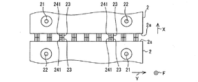
本発明の一実施形態である第1実施形態について図1〜図4を用いて説明する。図1は第1実施形態の電池パック1を構成する電池セル2の積層構造を説明する斜視図である。図2は図1の電池パックをII方向に見たときの電池セルの正面図である。図3は図1の電池パック1をIII方向に見たときの部分矢視図である。図4は電池セル2について他の形態である電池セル2Aを説明する正面図である。各図において、電池セル2が複数個積層して並ぶ方向を積層方向Xとし、直方体状の各電池セル2が水平方向に延びる方向を冷却流体の流れ方向Fとし、積層方向Xと冷却流体の流れ方向Fの両方に垂直な方向を複数の板状突部の並ぶ方向Y(以下、単にY方向ともいう)とする。
1st Embodiment which is one Embodiment of this invention is described using FIGS. 1-4. FIG. 1 is a perspective view illustrating a stacked structure of
図1において二点鎖線で示す複数個の電池セル2の集合体である電池パック1は、複数個の電池セル2の充電および放電または温度調節に用いられる電子部品(図示せず)によって制御され、図示しない送風部材による送風を受けて各電池セル2が冷却される。電池パック1は、電気的に直列接続された複数個の電池セル2をその側面を対向させるように並べて積層され、これらを一体化して構成されたものであり、図示しない筐体内に収納されている。上記の電子部品は、リレー、送風部材を駆動するモータ、インバータ等を制御する電子部品、各種の電子式制御装置等である。
A battery pack 1 that is an assembly of a plurality of
当該筐体は、メンテナンスのために少なくとも一面を取り外し可能に構成された直方体状のケースであり、樹脂または鋼板で形成されている。筐体には、車両側に筐体をボルト締め等により固定するための取付部、および機器収納ボックス(図示せず)が設けられている。 The housing is a rectangular parallelepiped case configured to be removable at least one surface for maintenance, and is formed of a resin or a steel plate. The casing is provided with an attachment portion for fixing the casing to the vehicle side by bolting or the like, and an equipment storage box (not shown).
当該機器ボックスには、電池状態(例えば電圧、温度等)を監視する各種センサ等からの検出結果が入力される電池監視ユニット(図示せず)と、電池監視ユニットと通信可能に構成されリレーを制御するとともに、送風部材のモータの駆動を制御する制御装置と、各機器を接続するワイヤハーネス等と、が収納されている。電池監視ユニットは、各電池セル2の状態を監視する電池ECU(電池の電子式制御ユニット)であり、電池パック1と多数の配線にて接続されている。
The device box includes a battery monitoring unit (not shown) to which detection results from various sensors that monitor the battery state (for example, voltage, temperature, etc.) are input, and a relay configured to be communicable with the battery monitoring unit. A control device that controls the driving of the motor of the blower member and a wire harness that connects each device are housed. The battery monitoring unit is a battery ECU (battery electronic control unit) that monitors the state of each
図1に示すように、電池パック1は、積層方向Xに直交する電池セルの側面2a,2b(方向Y及び方向Fに平行な側面)が拘束装置(図示せず)によって押圧されることにより、積層された複数の角形状の電池セル2が一体に保持して形成される電池セル集合体である。電池パック1を構成する複数の電池セル2は、電池パック1の積層方向Xの両端部に設置された拘束板(図示せず)がロッド(図示せず)によって連結されることにより、当該両端部から内側に向かう外力による圧縮力を受けて、拘束されることになる。例えば、複数の電池セル2は、4本の棒状のロッドによって圧縮力を受けて一体に固定されている。ロッドは、積層された複数の電池セル2を安定した力で押圧して一体化できるように、金属、硬質の樹脂等の強度に優れた材料で形成されている。
As shown in FIG. 1, the battery pack 1 is formed by pressing
次に、電池パック1を構成する各電池セル2について説明する。各電池セル2は、外装ケースによってその外周面を被覆された扁平状直方体である。各電池セル2には、正極端子21および負極端子22からなる二つの端子部がY方向に離れて配置されており、この端子部は外装ケースから冷却流体の流れ方向Fに突出するよう露出している。
Next, each
このように筐体内全体に配されたすべての電池セル2は、電池パック1の積層方向Xの一方端部側に位置する電池セル2における負極端子22から始まって、各電池セル2の端子部間を接続する各バスバー(図示せず)によって、電池パック1内をY方向に往復しながら電池パック1の積層方向Xの他方端部側に位置する電池セル2の正極端子21に至るまで通電可能に直列接続されている。このようにして積層方向Xに隣接する電池セル2間は電気的に接続されることになる。換言すれば、電池パック1を構成するすべての電池セル2は、積層方向Xの一方側端部に位置する電池セル2の端子部から積層方向Xの他方側端部に位置する電池セル2の端子部に至るまで、電流がジグザク状または蛇行状に流れるようにバスバーを介して電気的に直列接続される。
Thus, all the
積層方向Xに直交する電池セルの側面2a,2bには、冷却流体の流れ方向Fにそれぞれ延びる複数の板状突部241が設けられている。複数の板状突部241は、冷却流体の流れ方向Fと直交する方向Yに所定間隔をあけて並んでいる。複数の板状突部241は、隣合う電池セル2との間で冷却流体が流通する複数の通路を形成する。
On the side surfaces 2a and 2b of the battery cell orthogonal to the stacking direction X, a plurality of plate-
さらに電池セルの側面2a,2bには、冷却流体の流れ方向Fに延びる板状突部241の途中に複数の拡大突部23が設けられている。拡大突部23は、拘束装置により積層方向Xの拘束力が作用した場合に隣合う電池セル2側と接触して当接するように配置されており、隣合う電池セル2からの作用力を受ける。拡大突部23は、複数の板状突部の並ぶ方向Yについての外形寸法が板状突部241の板厚寸法よりも大きく形成されている。本実施形態では、拡大突部23は円筒状のいわゆるボス部を形成するが、このような形状に限定するものではない。
Further, on the side surfaces 2a and 2b of the battery cell, a plurality of
図1及び図2に示すように、拡大突部23は、1個の板状突部241の途中に所定間隔をあけて複数個(図では2または3個)設けられている。すなわち、冷却流体の流れ方向Fについて1個の拡大突部23の両側には拡大突部23が設けられている。拡大突部23は、積層方向Xに直交する電池セルの側面2a,2bにおいて千鳥状に配されているので、各拡大突部23についてY方向の隣には板状突部241が存在している。このような構成により、拡大突部23と板状突部241は、複数の板状突部の並ぶ方向Yに交互に配置されていることになる。
As shown in FIGS. 1 and 2, a plurality (two or three in the figure) of the
拡大突部23と板状突部241は、積層方向Xの突出高さが同等または拡大突部23の方がわずかに高く形成されている。これにより、図3に図示するように、拘束装置により各電池セル2に積層方向Xの拘束力が作用したときに、少なくとも隣合う電池セル2における拡大突部23同士が接触して作用し合うようになっている。このとき、隣合う電池セル2における板状突部241同士は、接触してもよいし、離間してもよい。
The
このように電池セル2において、複数の拡大突部23は各電池セルに作用する拘束力に対して耐えうる拘束強度を発揮する機能を有し、複数の板状突部241は、冷却流体に接触することにより電池セル2の伝熱面積を拡大する部分であり、電池セル2の熱を冷却流体へ放出するための伝熱経路として機能する。
As described above, in the
本実施形態では、拡大突部23は、電池セル2の外装ケースに形成されている突起であり、板状突部241は電池セル2とは別部品である別個のプレート部材24に形成されている。金属製のプレート部材24には、プレス加工等により、複数の板状突部241と各拡大突部23が通る穴部とが形成されている。すなわち、プレート部材24は、複数の拡大突部23すべてが挿通可能な穴部を有する金属製のフィン付きプレートである。
In the present embodiment, the
別個のプレート部材24は積層方向Xに直交する電池セルの側面2a,2bに例えば一体成形により設けられる。拡大突部23が一体に形成された外装ケースは、例えば、絶縁性を有するあらゆる樹脂で形成され、ポリプロピレン、ポリエチレン、ポリスチレン、塩化ビニル、フッ素系樹脂、PBT、ポリアミド、ポリアミドイミド(PAI樹脂)、ABS樹脂(アクリロニトリル、ブタジエン、スチレンの共重合合成樹脂)、ポリアセタール、ポリカーボネート、ポリブチレンテレフタレート、ポリエチレンテレフタレート、ポリフェニレンスルファイド、フェノール、エポキシ、アクリル等の樹脂で形成することができる。
The
このような別個のプレート部材24を採用することにより、電池セル2の外装ケースと拡大突部23または板状突部241とを異なる材質で形成することができる。例えば、板状突部を形成する別個の部材を熱伝導性に優れた材質にすれば、電池セルの冷却性能を向上することができる。
By employing such a
また他の形態では、板状突部241は電池セル2の外装ケースに形成したフィンとし、拡大突部23が電池セル2とは別個のプレート部材に形成されるように構成してもよい。
In another embodiment, the plate-
また他の形態では、例えば図4に図示するように、拡大突部23と板状突部241の両方を一体とした同一の部材24Aにおいて形成するようにしてもよい。この構成によれば、電池セル2Aの外装ケースに拡大突部23等の突出物を形成する必要がなくなる。したがって、電池セル2Aの外装ケースの汎用性が向上する。
In another embodiment, as shown in FIG. 4, for example, both the
また、当該同一の部材は、電池セル2とは別個のプレート部材であってもよい。この場合には、拡大突部23と板状突部241の両方が形成された同一の部材は積層方向Xに直交する電池セルの側面に例えばインサート成形等の一体成形により設けることができる。
Further, the same member may be a plate member separate from the
また、図4のように、当該同一の部材は、隣合う電池セル2間に挟みこまれるスペーサ24Aであってもよい。この構成によれば、電池セル2と当該スペーサとを交互に配した集合体に拘束力をかけることにより、電池セル2の冷却性能の向上と電池セル2に与える拘束強度の確保の両立が図れる。
As shown in FIG. 4, the same member may be a
また、拡大突部23及び板状突部は電池セル2の外装ケースに一体成形されて形成される形態であってもよい。これによれば、部品点数の低減及び生産コストの低減が図れる。
Further, the
さらに、電池セル2の外装ケースと拡大突部23もしくは板状突部241とが導電性材料で形成されている場合には、拡大突部23もしくは板状突部241における隣合う電池セル側との接触部位及び隣合う電池セル側における拡大突部23もしくは板状突部241との接触部位の少なくとも一方は、絶縁性物質で被覆されていることが好ましい。当該部位における絶縁性物質の被覆は、蒸着、コーティング、一体成形等によって形成することができる。このような構成によれば、隣合う電池セル間で接触する部位同士が絶縁性物質の被覆部分を介して接触するようになるため、電池セル間の電気絶縁性が確保され、電池性能の発揮及び電気的安全性の確保を図ることができる。また、隣合う電池セル2間の電位差により、導電性材料部分が腐食する事態を抑制し得る。
Furthermore, when the exterior case of the
本実施形態の電池パック1がもたらす作用効果について述べる。電池パック1は、電池パック1は、積層方向Xに直交する電池セル2の側面に冷却流体の流れ方向Fに延びるように設けられる板状突部であって、冷却流体の流れ方向Fと直交する方向Yに並ぶように設けられ、隣合う電池セル2との間で通路を形成する複数の板状突部241と、冷却流体の流れ方向Fに延びる板状突部241の途中に複数設けられて、隣合う電池セル2側と接触して隣合う電池セル2からの作用力を受ける複数の拡大突部23と、を備える。各拡大突部23は、複数の板状突部の並ぶ方向Yについての外形寸法が板状突部241の板厚寸法よりも大きく形成されている。
The effect which the battery pack 1 of this embodiment brings is described. The battery pack 1 is a plate-like protrusion provided on the side surface of the
この構成によれば、それぞれ冷却流体の流れ方向Fに延び、冷却流体の流れ方向Fと直交する方向Yに並ぶ板状突部によって、電池セル2の側面における冷却機能を果たす伝熱面積が大きくなるため冷却性能を高めることができる。この板状突部241は冷却性能を十分発揮できる範囲で可能な限り薄くしているので、冷却流体通路断面積をほとんど小さくすることなく、伝熱面積を拡大することができるため、より少ない冷却媒体の流量で、より小さな流体機器の動力で、またより低い騒音で、必要な冷却性能を発揮することができる。
According to this configuration, the plate-shaped protrusions that extend in the cooling fluid flow direction F and are aligned in the direction Y orthogonal to the cooling fluid flow direction F have a large heat transfer area that performs the cooling function on the side surface of the
さらに、隣合う電池セル2側と接触して隣合う電池セル2からの作用力を受ける拡大突部23は、冷却流体の流れ方向に延びる板状突部241の途中に複数設けられているため、電池セル2の側面の受ける拘束力が過剰に偏ることなく分散させることが可能である。これによって、当該拘束力が特定箇所に集中することを軽減できるので各電池セル2の拘束強度を確保することができる。
Furthermore, a plurality of
さらに拡大突部23は、複数の板状突部の並ぶ方向Yについての外形寸法が板状突部241の板厚寸法よりも大きく形成されていることにより、拡大突部23の当該外形寸法を必要な拘束強度を確保できる大きさに大きくすれば拘束強度を向上して振動等による影響を受けにくい電池パックを提供できる。したがって、電池セル2の冷却性能の向上と電池セル2に与える拘束強度確保の両立を図ることができる。
Further, the
また、板状突部241は、放熱用のフィン部材として機能し得るため、その板厚を冷却性能を十分発揮できる範囲で可能な限り薄くすることにより、冷却流体通路の断面積をほとんど縮小することなく、板状突部241からの放熱量が増加して放熱性能の向上が図れる。
Further, since the plate-
また、板状突部241の延長方向の途中に設けられる拡大突部23は複数の板状突部の並ぶ方向Yについての外形寸法が板状突部241の板厚寸法よりも大きく形成されていることにより、電池セル2間に形成される冷却流体通路は、拡大突部23と板状突部241とが対向する部位では2つの板状突部241が対向する部位に比べて通路断面積が狭くなる。これにより、冷却流体通路を流れる流体は拡大突部23と板状突部241とが対向する部位で板状突部241寄りに流れるため、蛇行するような流れを形成しやすい。このような流れの形成によって冷却流体流れの伝熱面の境界層を薄く形成することができるため、熱伝達性能を向上することができ、冷却性能を向上できる。
The
また、拡大突部23と板状突部241は複数の板状突部の並ぶ方向Yに交互に配置されていることにより、電池セル2間に形成される冷却流体通路は、冷却流体の流れ方向Fにおいて拡大突部23が形成されている部位では他の部位に比べて通路断面積が狭くなる。したがって、冷却流体通路は、冷却流体の流れ方向Fにおいて、通路断面積の狭い部分と広い部分とを交互に繰り返す通路に形成される。これにより、冷却流体通路を流れる流体は拡大突部23が存在する部分で対向する板状突部241側に流れが曲がり、その後元に戻り、再び拡大突部23の存在部位で板状突部241側に曲がるような流れとなる。このため、蛇行するような流れが形成されることによって冷却流体流れの伝熱面の境界層を薄く形成することができるため、熱伝達性能を向上することができ、冷却性能を向上できる。
In addition, the
(第2実施形態)
第2実施形態では、第1実施形態に対して他の形態である電池セル3を用いる電池パックについて図5を参照して説明する。図5は第2実施形態の電池パックを構成する電池セル3の積層構造を説明する部分平面図である。
(Second Embodiment)
In 2nd Embodiment, the battery pack using the
図5に示すように、電池セル3の積層構造は、図3に示す電池セル2の積層構造に対して、拘束装置により積層方向Xの拘束力が作用した場合に、隣合う電池セル3間で拡大突部33同士及び拡大突部35同士が直接に接触するのではなく、拡大突部33及び拡大突部35はそれぞれ電池セルの側面3b、3aに接触して拘束力に耐え得る拘束強度を発揮する点で相違する。他の構成は同様であり同様の作用効果を奏する。
As shown in FIG. 5, the stacked structure of the
(第3実施形態)
第3実施形態では、第1実施形態に対して他の形態である電池セルの積層構造について図6及び図7を参照して説明する。図6は第3実施形態の電池パックを構成する電池セル4を説明する正面図である。図7は第3実施形態の隣合う電池セル4の積層構造を説明する部分平面図である。
(Third embodiment)
3rd Embodiment demonstrates the laminated structure of the battery cell which is another form with respect to 1st Embodiment with reference to FIG.6 and FIG.7. FIG. 6 is a front view for explaining the
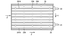
第3実施形態の隣合う電池セル4の積層構造は、第1実施形態に対して、拡大突条部43の形状と、拡大突条部43と板状突部44の位置関係が相違しているが他の構成は同様であり同様の作用効果を奏する。以下、第1実施形態と異なる点についてのみ説明する。
The stacked structure of the
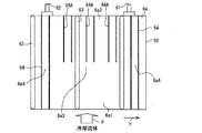
拡大突条部43は、積層方向Xに直交する電池セルの側面4aに、冷却流体の流れ方向Fに延びるレール形状であり、同方向の電池セルの側面4a全域にわたっている。複数の拡大突条部43は、冷却流体の流れ方向Fと直交する方向Yに間隔をあけて設けられている。そして、拘束装置によって各電池セル4に積層方向Xの拘束力が作用した場合には、複数の拡大突条部43は、隣合う電池セル側と接触して隣合う電池セル4からの作用力を受ける。さらに各拡大突条部43は、複数の板状突部の並ぶ方向Yについての幅寸法が板状突部44の厚み寸法よりも大きく形成されている。すなわち、拡大突条部43は薄板状の板状突部44に比べて板厚が大きいため、大きな強度を有し、積層方向Xに作用する力に対して変形しにくい強度を備えている。
The
拡大突条部43は、本実施形態では図6及び図7に図示するように、複数の板状突部の並ぶ方向Yに所定間隔をあけて複数(本実施形態では6個)並んで配置されている。このように間隔をあけて設けられた拡大突条部43間には、複数個の板状突部44(本実施形態では4個)が並んで配置されている。すなわち、拡大突条部43の個数は、板状突部44の個数よりも少なく、ゆえに電池セルの側面4aにおける単位面積当たりの拡大突条部43の個数は、当該単位面積当たりの板状突部44の個数よりも少ない。
In this embodiment, as shown in FIGS. 6 and 7, the
したがって、複数の拡大突条部43は、Y方向の厚みが大きく形成されているため、隣合う電池セル4に設けられた複数の拡大突条部43と接触したときに拘束力による圧縮方向の力を受ける強度を有する機能を発揮する。さらに拡大突条部43間に配置される複数の板状突部44は、隣合う電池セル4との間で冷却流体の通路の中で伝熱面積を拡大する機能を有し、放熱性能を向上する機能を発揮する。
Therefore, since the plurality of
また、拡大突条部43及び板状突部44は、冷却流体の流れ方向Fと直交する方向Yについて電池セルの側面4a全域にわたって均等に配置されている。隣合う電池セル4間における板状突部44同士は、互いの頂面が対向する位置関係にある。なお、隣合う電池セル4間における板状突部44同士は接触する位置関係でもよいし、離間する位置関係であってもよい。
Further, the
第3実施形態では、拡大突条部43は、電池セル4の外装ケースに形成されている突起であり、板状突部44は電池セル4とは別部品である別個のプレート部材に形成されている。この金属製のプレート部材には、プレス加工等により、複数の板状突部44と各拡大突条部43が通る細長い矩形状の穴部とが形成されている。すなわち、当該プレート部材は、複数の拡大突条部43すべてが挿通可能な穴部を有する金属製のフィン付きプレートである。
In the third embodiment, the
別個のプレート部材は積層方向Xに直交する電池セルの側面4aに例えば一体成形により設けられる。拡大突条部43が一体に形成された外装ケースは、例えば、絶縁性を有するあらゆる樹脂で形成され、ポリプロピレン、ポリエチレン、ポリスチレン、塩化ビニル、フッ素系樹脂、PBT、ポリアミド、ポリアミドイミド(PAI樹脂)、ABS樹脂(アクリロニトリル、ブタジエン、スチレンの共重合合成樹脂)、ポリアセタール、ポリカーボネート、ポリブチレンテレフタレート、ポリエチレンテレフタレート、ポリフェニレンスルファイド、フェノール、エポキシ、アクリル等の樹脂で形成することができる。
The separate plate member is provided on the
また他の形態では、板状突部44は電池セル4の外装ケースに形成したフィンとし、拡大突条部43が電池セル4とは別個のプレート部材に形成されるように構成してもよい。
In another embodiment, the plate-
また他の形態では、拡大突条部43と板状突部44の両方を同一の部材において形成するようにしてもよい。また、当該同一の部材は、電池セル4とは別個のプレート部材であってもよい。この場合には、拡大突条部43と板状突部44の両方が形成された同一の部材は積層方向Xに直交する電池セルの側面に例えばインサート成形等の一体成形により設けることができる。
In another form, both the
また、当該同一の部材は、隣合う電池セル4間に挟みこまれるスペーサであってもよい。この構成によれば、電池セル4と当該スペーサとを交互に配した集合体に拘束力をかけることにより、電池セル4の冷却性能の向上と電池セル4に与える拘束強度の確保の両立が図れる。
The same member may be a spacer sandwiched between
また、拡大突状部43及び板状突部44は電池セル4の外装ケースに一体成形されて形成される形態であってもよい。これによれば、部品点数の低減及び生産コストの低減が図れる。
Further, the enlarged projecting
さらに、拡大突条部43または板状突部44及び電池セル4の外装ケースが導電性材料で形成されている場合には、拡大突条部43または板状突部44における隣合う電池セル側との接触部位及び隣合う電池セル側における拡大突条部43または板状突部44との接触部位の少なくとも一方は、絶縁性物質で被覆されていることが好ましい。当該部位における絶縁性物質の被覆は、蒸着、コーティング、一体成形等によって形成することができる。このような構成によれば、隣合う電池セル間で接触する部位同士が絶縁性物質の被覆部分を介して接触するようになるため、電池セル間の電気絶縁性が確保され、電池性能の発揮及び電気的安全性の確保を図ることができる。また、隣合う電池セル4間の電位差により、導電性材料部分が腐食する事態を抑制し得る。
Further, when the
本実施形態の電池パックがもたらす作用効果について述べる。電池パックは、積層方向Xに直交する電池セルの側面4aに冷却流体の流れ方向Fに延びる板状突部44を冷却流体の流れ方向Fと直交する方向Yに並べて配置して、隣合う電池セル4との間で通路を形成する複数の板状突部44と、積層方向Xに直交する電池セルの側面4aに、冷却流体の流れ方向Fに延びる形状の拡大突条部43を冷却流体の流れ方向Fと直交する方向Yに間隔をあけて設け、隣合う電池セル4側と接触して隣合う電池セル4からの作用力を受ける複数の拡大突条部43と、を備えている。拡大突条部43は、複数の板状突部の並ぶ方向Yについての幅寸法が板状突部44の厚み寸法よりも大きく形成され、間隔をあけて設けられた拡大突条部43間には、複数個の板状突部44が並んで配置されている。
The effect which the battery pack of this embodiment brings is described. The battery pack is configured by arranging plate-
この構成によれば、複数の必要な厚み寸法の拡大突条部43が電池セルの側面4aに必要間隔で分散して配置されているため、電池セル4に必要な拘束を加える機能を安定的に果たすことができる。その上で、拡大突条部43の間に設けられた複数の板状突部44によって電池セルの側面4aにおける冷却機能を果たす伝熱面積が大きくなるため冷却性能を高めることができる。この板状突部44は冷却性能を十分発揮できる範囲で可能な限り薄くできるので、冷却流体通路断面積をほとんど小さくすることなく、伝熱面積を拡大することができるため、より少ない冷却媒体の流量で、より小さな流体機器の動力で、またより低い騒音で、必要な冷却性能を発揮することができる。したがって、電池セル4間の冷却性能の向上と電池セル4に与える拘束強度の確保の両立が図れる。
According to this configuration, since the plurality of
また、板状突部44は、放熱用のフィン部材として機能し得るため、その板厚を可能な限り薄くすることにより、冷却流体通路の断面積の拡大が可能になることに加え、板状突部44からの放熱量が増加して冷却性能の向上が図れる。
Further, since the plate-
(第4実施形態)
第4実施形態では、第3実施形態に対して他の形態である電池セル4Aの積層構造について図8及び図9を参照して説明する。図8は第4実施形態の電池パックを構成する電池セル4Aを説明する正面図である。図9は隣合う電池セル4Aの積層構造を説明する部分平面図である。
(Fourth embodiment)
4th Embodiment demonstrates the laminated structure of the
図8及び図9に示すように、電池セル4Aの積層構造は、第3実施形態に示す電池セル4の積層構造に対して、拘束装置により積層方向Xの拘束力が作用した場合に、隣合う電池セル4A間における板状突部44A及び板状突部46A同士は、互いの頂面が対向する位置関係にあるのではなく、隣合う一方の電池セル4Aの板状突部44A,46Aが他方の電池セル4Aの板状突部44A,46Aに対してY方向にずれる位置関係にある点で相違する。このため板状突部44A,46Aの高さが拡大突条部43A,45Aより仮に高くても、隣り合った板状突部44Aまたは46A同士が干渉して変形することを防止できる。拡大突条部43A,45Aを含む他の構成は同様であり同様の作用効果を奏する。
As shown in FIGS. 8 and 9, the stacked structure of the
(第5実施形態)
第5実施形態では、第4実施形態に対して他の形態である電池セル5の積層構造について図10及び図11を参照して説明する。図10は第5実施形態の電池パックを構成する電池セル5を説明する正面図である。図11は隣合う電池セル5の積層構造を説明する部分平面図である。
(Fifth embodiment)
5th Embodiment demonstrates the laminated structure of the
図10及び図11に示すように、電池セル5の積層構造は、第4実施形態に示す電池セル4Aの積層構造に対して、電池セルの側面5a,5bに間隔をあけて設けられた拡大突条部53間及び拡大突条部55間に、並ぶ板状突部54,56の個数が相違する。
As shown in FIGS. 10 and 11, the stacked structure of the
拡大突条部53,55はそれぞれ、本実施形態では図10及び図11に図示するように、複数の板状突部の並ぶ方向Yに所定間隔をあけて6個並んで配置されている。このように間隔をあけて設けられた拡大突条部53間及び拡大突条部55間のそれぞれには、複数個の板状突部54,56(本実施形態では2個)が並んで配置されている。すなわち、拡大突条部53,55の個数は、板状突部54,56の個数よりも少なく、ゆえに電池セルの側面5a,5bにおける単位面積当たりの拡大突条部53,55の個数は、当該単位面積当たりの板状突部54,56の個数よりも少ない。
In the present embodiment, as shown in FIGS. 10 and 11, six
また拘束装置により積層方向Xの拘束力が作用した場合に、隣合う電池セル5間における拡大突条部53同士及び拡大突条部55同士は当接する。一方、隣合う電池セル5間における板状突部54同士及び板状突部56同士は、互いの頂面が対向する位置関係にあるのではなく、隣合う一方の電池セル5の板状突部54,56が他方の電池セル5の板状突部54,56に対してY方向にずれる位置関係にある。また、板状突部54,56の高さは拡大突条部53,55の高さより高い。また本実施形態は、第4実施形態と同様な効果を奏する。
Further, when a restraining force in the stacking direction X is applied by the restraining device, the
(第6実施形態)
第6実施形態では、第5実施形態に対して他の形態である電池セル5Aの積層構造について図12及び図13を参照して説明する。図12は第6実施形態の電池パックを構成する電池セル5Aを説明する正面図である。図13は隣合う電池セル5Aの積層構造を説明する部分平面図である。
(Sixth embodiment)
In the sixth embodiment, a stacked structure of
図12及び図13に示すように、電池セル5Aの積層構造は、第5実施形態に示す電池セル5の積層構造に対して、板状突部54A及び板状突部56Aはその先端が根元部分に対して細い先細り状である点で相違する。このような板状突部54A及び板状突部56Aの形状によれば、例えば板状突部54及び板状突部56と同等の放熱性能を有する場合であっても、板状突部の断面積を小さくできるので、流路抵抗の低減、当該低減による送風機等の流体輸送機器の動力低減、騒音低減が図れる。また、拡大突条部53,55を含む他の構成は同様であり同様の作用効果を奏する。
As shown in FIGS. 12 and 13, the stacked structure of the
(第7実施形態)
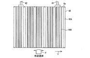
第7実施形態では、第5実施形態に対して他の形態である電池セル6を用いる電池パックについて図14及び図15を参照して説明する。図14は第7実施形態の電池パックを構成する電池セル6を説明する正面図である。図15は隣合う電池セル6の積層構造を説明する部分平面図である。
(Seventh embodiment)
7th Embodiment demonstrates the battery pack using the
図14及び図15に示すように、電池セル6の積層構造は、第5実施形態に示す電池セル5の積層構造に対して、拘束装置により積層方向Xの拘束力が作用した場合に、隣合う電池セル6間で拡大突条部63同士及び拡大突条部65同士が直接に接触するのではなく、拡大突条部63及び拡大突条部65はそれぞれ電池セルの側面6a、6bに接触して拘束力に耐え得る拘束強度を発揮する点で相違する。他の構成は同様であり同様の作用効果を奏する。このような構成によれば、電池セル6を積層配置するときに、第5実施形態に比べてY方向の位置ずれが生じてもその影響を小さくでき、拘束強度を確実に発揮させることができる。
As shown in FIGS. 14 and 15, the stacked structure of the
また、拡大突条部63及び65はそれぞれ、本実施形態では図14及び図15に図示するように、複数の板状突部の並ぶ方向Yに所定間隔をあけて3個並んで、しかも一方側に偏るように配置されている。このように間隔をあけて設けられた拡大突条部63間及び拡大突条部65間のそれぞれには、複数個の板状突部64,66(本実施形態では4個)が並んで配置されている。すなわち、拡大突条部63,65の個数は、板状突部64,66の個数よりも少なく、ゆえに電池セルの側面6a,6bにおける単位面積当たりの拡大突条部63,65の個数は、当該単位面積当たりの板状突部64,66の個数よりも少ない。
Further, in this embodiment, as shown in FIGS. 14 and 15, the three
(第8実施形態)
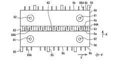
第8実施形態では、第7実施形態に対して他の形態である電池セル6Aを用いる電池パックについて図16及び図17を参照して説明する。図16は第8実施形態の電池パックを構成する電池セル6Aを説明する正面図である。図17は隣合う電池セル6Aの積層構造を説明する部分平面図である。
(Eighth embodiment)
In the eighth embodiment, a battery pack using a
図16及び図17に示すように、電池セル6Aの積層構造は、第7実施形態に示す電池セル6の積層構造に対して、板状突部64A及び板状突部66Aは、積層方向Xに直交する電池セルの側面6a,6bにおいて冷却流体流れの上流側部分6a1よりも下流側部分6a2に多く配置されている点で相違する。他の構成は同様であり同様の作用効果を奏する。
As shown in FIGS. 16 and 17, the laminated structure of the
電池セルの側面6a,6bの板状突部64A及び66Aはそれぞれ、図16及び図17に図示するように、複数の板状突部の並ぶ方向Yの幅全域に設けられており、第7実施形態の板状突部64よりも冷却流体の流れ方向Fに短く、冷却流体流れの上流側部分6a1には配置されず、下流側部分6a2のみに配置されている。
The plate-
このような構成によれば、電池セルの側面6a,6bにおける伝熱面積を冷却流体流れの上流側部分6a1よりも下流側部分6a2の方を大きくすることができる。これにより、冷却流体流れの上流側よりも下流側で冷却流体による電池セル6Aの冷却を促進することが可能になり、冷却流体流れの上流側及び下流側における冷却能力を互いに近づけることができる。したがって、電池セルの側面6a,6bにおける冷却能力の差を低減して、電池セル6Aの部分間の温度ばらつきを抑制でき、電池性能の適正な発揮に寄与し得る。
According to such a configuration, the heat transfer area on the side surfaces 6a and 6b of the battery cell can be made larger in the downstream portion 6a2 than in the upstream portion 6a1 of the cooling fluid flow. Thereby, it becomes possible to promote the cooling of the
(第9実施形態)
第9実施形態では、第7実施形態に対して他の形態である電池セル6Bを用いる電池パックについて図18を参照して説明する。図18は第9実施形態の電池パックを構成する電池セル6Bを説明する正面図である。
(Ninth embodiment)
In the ninth embodiment, a battery pack that uses
図18に示すように、電池セル6Bの積層構造は、第7実施形態に示す電池セル6の積層構造に対して、電池セルの側面6aにおいて冷却流体の流れ方向Fと直交する方向Yで伝熱面積を変化させる構成を有する点で相違する。このような構成の一例として第9実施形態では、積層方向Xに直交する電池セルの側面6aにおいて複数の板状突部の並ぶ方向Yの中央側部分6a3よりも両側部分6a4に板状突部64を多く配置している。なお、他の構成は第7実施形態と同様であり同様の作用効果を奏する。
As shown in FIG. 18, the stacked structure of the
第9実施形態の板状突部64の配置に係る構成によれば、電池セルの側面6a,6bにおける伝熱面積を複数の板状突部の並ぶ方向Yの中央側部分6a3よりも両側部分6a4の方を大きくすることができる。すなわち、電池セルの側面6aにおいて板状突部64は、図18に図示するように、Y方向幅の中央部には配置されず、Y方向幅の中央部以外の部分に配置されている。ゆえに電池セルの側面6aにおける単位面積当たりの板状突部64の個数は、Y方向幅の中央部よりもそれ以外の部分(特に両側部分6a4)で多いため、単位面積当たりの伝熱面積も冷却流体流れの中央部側よりも両側で大きくなっている。
According to the configuration relating to the arrangement of the plate-
これにより、電池セル6B間に形成される冷却流体通路が並ぶ幅において、中央側よりも両側で冷却流体による電池セル6Bの冷却を促進することが可能になり、電池セル6Bの当該両側部分における放熱が大きい場合や当該両側部分の冷却性能を向上させる必要がある場合には、電池セルの側面6a,6bにおける複数の板状突部の並ぶ方向Yの冷却能力を変えることができ、また互いに近づけることもできる。このように電池セルの側面6aにおける冷却能力を電池セル6Bの部分的な発熱密度の違いに応じて変えることができれば、電池セル6Bの部分間の温度ばらつきを抑制することができ、電池性能の適正な発揮に寄与し得る。
Thereby, in the width in which the cooling fluid passages formed between the
(第10実施形態)
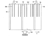
第10実施形態では、第7実施形態に対して他の形態である電池セル6Cを用いる電池パックについて図19及び図20を参照して説明する。図19は第10実施形態の電池パックを構成する電池セル6Cを説明する正面図である。図20は隣合う電池セル6Cの積層構造を説明する部分平面図である。
(10th Embodiment)
In the tenth embodiment, a battery pack using
図19及び図20に示すように、電池セル6Cの積層構造は、第7実施形態に示す電池セル6の積層構造に対して、板状突部64A及び板状突部66Aは、積層方向Xに直交する電池セルの側面6a,6bにおいて冷却流体流れの上流側部分6a1よりも下流側部分6a2に多く配置されている点で相違する。他の構成は同様であり同様の作用効果を奏する。
As shown in FIGS. 19 and 20, the stacked structure of the
電池セルの側面6a,6bのY方向の中央部分6a3に位置する板状突部64A及び66Aはそれぞれ、図19及び図20に図示するように、両側部分6a4に位置する板状突部64及び66よりも冷却流体の流れ方向Fに短く、冷却流体流れの上流側部分6a1には配置されず、下流側部分6a2のみに配置されている。ゆえに電池セルの側面6a,6bにおける単位面積当たりの板状突部の個数は、冷却流体流れの下流側部分6a2よりも上流側部分6a1で少ないため、単位面積当たりの伝熱面積も冷却流体流れの中央部分の下流側よりも上流側で少なくなっている。
The plate-
このような構成によれば、電池セルの側面6a,6bの中央部分における伝熱面積を冷却流体流れの下流側部分6a2よりも上流側部分6a2の方を小さくすることができる。これにより、電池セル6Cの中央上流部の発熱密度が低い場合に、電池セル6Cの両側部分と中央部分の下流側部分で冷却流体による電池セル6Cの冷却を促進することが可能になる。このように、電池セルの側面6a,6bにおける冷却能力を電池セル6Cの部分的な発熱密度の違いに応じて変えることができれば、電池セル6Cの部分間の温度ばらつきを抑制でき、電池性能の適正な発揮に寄与し得る。
According to such a configuration, the heat transfer area in the central portion of the side surfaces 6a and 6b of the battery cell can be made smaller in the upstream portion 6a2 than in the downstream portion 6a2 of the cooling fluid flow. Accordingly, when the heat generation density in the central upstream portion of the
(第11実施形態)
第11実施形態では、第10実施形態に対して他の形態である電池セル6Dを用いる電池パックについて図21を参照して説明する。図21は第11実施形態の電池パックを構成する電池セル6Dを説明する正面図である。
(Eleventh embodiment)
In the eleventh embodiment, a battery pack using
図21に示すように、電池セル6Dの積層構造は、第10実施形態に示す電池セル6Cの積層構造に対して、上流側部分6a1に配されず下流側部分6a2に配される板状突部64A及び板状突部66Aは、Y方向の全域に設けられている点と、複数の板状突部の並ぶ方向Yの両側部分6a4よりも中央側部分6a3に多く配置されている点と、で相違する。このような第11実施形態においても第10実施形態と同様の作用効果を奏する。
As shown in FIG. 21, the laminated structure of the
つまり、電池セル6Dの積層構造は、第7実施形態に示す電池セル6の積層構造に対して、電池セルの側面6aにおいて複数の板状突部の並ぶ方向Yで伝熱面積を変化させる構成を有する点で相違する。このような構成の一例として第11実施形態では、積層方向Xに直交する電池セルの側面6aにおいて複数の板状突部の並ぶ方向Yの両側部分6a4よりも中央側部分6a3に板状突部64Aを多く配置している。なお、他の構成は第7実施形態と同様であり同様の作用効果を奏する。
That is, the stacked structure of the
このように第11実施形態の板状突部64Aの配置に係る構成によれば、電池セルの側面6aにおける伝熱面積を複数の板状突部の並ぶ方向Yの両側部分6a4よりも中央側部分6a3の方を大きくすることができる。これにより、電池セル6D間に形成される冷却流体通路が並ぶ幅において、両側よりも中央側で冷却流体による電池セル6Dの冷却を促進することが可能になり、電池セル6Dの当該中央側部分6a3における放熱が大きい場合や当該中央側部分6a3の冷却性能を向上させる必要がある場合には、電池セルの側面6aにおける複数の板状突部の並ぶ方向Yの冷却能力を変えることができ、また互いに近づけることもできる。このように電池セルの側面6aにおける冷却能力を電池セル6Dの部分的な発熱密度の違いに応じて変えることができれば、電池セル6Dの部分間の温度ばらつきを抑制することができ、電池性能の適正な発揮に寄与し得る。
Thus, according to the structure which concerns on arrangement | positioning of the plate-shaped
(他の実施形態)
上述の実施形態では、本発明の好ましい実施形態について説明したが、本発明は上述した実施形態に何ら制限されることなく、本発明の主旨を逸脱しない範囲において種々変形して実施することが可能である。
(Other embodiments)
In the above-described embodiment, the preferred embodiment of the present invention has been described. However, the present invention is not limited to the above-described embodiment, and various modifications can be made without departing from the spirit of the present invention. It is.
上記実施形態において、拡大突部23、板状突部241、拡大突条部43、板状突部44等の各部は、当該各部が形成された別個の部材を電池セルの外装ケースに対して固着またはインサート成形等の一体成形により、一体にして電池セルの側面に設けるようにしたものでもよいし、電池セルの外装ケースに直接形成されているものであってもよい。
In the above-described embodiment, each of the
上記実施形態において、電池セルの側面に設けられる拡大突部23、板状突部241、拡大突条部43、板状突部44等の各部は、隣合う電池セル側と接触するように説明されているが、これは、当該各部が隣合う電池セルの外装ケースに直接的に接触する形態であってもよいし、隣合う電池セルの側面に設けられた当該各部と直接的に接触する形態であってもよい。
In the above embodiment, each of the
1…電池パック
2,4…電池セル
23…拡大突部
43…拡大突条部
44,241…板状突部
64,64A…板状突部
F…冷却流体の流れ方向
X…積層方向
Y…複数の板状突部の並ぶ方向
DESCRIPTION OF SYMBOLS 1 ...
Claims (17)
前記積層方向(X)に直交する前記電池セルの側面に前記冷却流体の流れ方向(F)に延びるように設けられる板状突部であって、前記冷却流体の流れ方向(F)と直交する方向(Y)に並ぶように設けられ、隣合う電池セルとの間で前記通路を形成する複数の板状突部(241)と、
前記冷却流体の流れ方向(F)に延びる前記板状突部の途中に複数設けられて、前記隣合う電池セル側と接触して前記隣合う電池セルからの作用力を受ける複数の拡大突部(23)と、を備え、
前記拡大突部(23)は、前記複数の板状突部の並ぶ方向(Y)についての外形寸法が前記板状突部の板厚寸法よりも大きく形成されていることを特徴とする電池パック。 The plurality of stacked battery cells (2) are configured to be pressed and held together in the stacking direction (X), and a cooling fluid is allowed to flow through a passage formed between adjacent battery cells. In the battery pack (1) to be cooled,
A plate-like protrusion provided on a side surface of the battery cell orthogonal to the stacking direction (X) so as to extend in the flow direction (F) of the cooling fluid, and orthogonal to the flow direction (F) of the cooling fluid A plurality of plate-like protrusions (241) provided so as to be aligned in the direction (Y) and forming the passage between adjacent battery cells;
A plurality of enlarged protrusions provided in the middle of the plate-like protrusions extending in the flow direction (F) of the cooling fluid and receiving the acting force from the adjacent battery cells in contact with the adjacent battery cell side (23)
The battery pack, wherein the enlarged protrusion (23) is formed such that an outer dimension in a direction (Y) in which the plurality of plate-like protrusions are arranged is larger than a plate thickness dimension of the plate-like protrusion. .
前記拡大突部または前記板状突部における前記隣合う電池セル側との接触部位及び前記隣合う電池セル側における前記拡大突部または前記板状突部との接触部位の少なくとも一方は、絶縁性物質で被覆されていることを特徴とする請求項1から請求項5のいずれか一項に記載の電池パック。 The enlarged protrusion or the plate-like protrusion and the outer case of the battery cell are formed of a conductive material,
At least one of the contact portion with the adjacent battery cell side in the enlarged protrusion or the plate-like protrusion and the contact portion with the enlarged protrusion or the plate-like protrusion on the adjacent battery cell side is insulative. The battery pack according to claim 1, wherein the battery pack is coated with a substance.
前記積層方向(X)に直交する前記電池セルの側面に前記冷却流体の流れ方向(F)に延びる板状突部(44)を前記冷却流体の流れ方向(F)と直交する方向(Y)に並べて配置して、隣合う電池セルとの間で前記通路を形成する複数の板状突部(44)と、
前記積層方向(X)に直交する前記電池セルの側面に、前記冷却流体の流れ方向(F)に延びる形状の拡大突条部(43)を前記冷却流体の流れ方向(F)と直交する方向(Y)に間隔をあけて設け、前記隣合う電池セル側と接触して前記隣合う電池セルからの作用力を受ける複数の拡大突条部(43)と、を備え、
前記拡大突条部(43)は、前記複数の板状突部の並ぶ方向(Y)についての幅寸法が前記板状突部の厚み寸法よりも大きく形成され、
前記間隔をあけて設けられた拡大突条部(43)間には、複数個の前記板状突部が並んで配置されていることを特徴とする電池パック。 A plurality of stacked battery cells (4) are pressed and held together in the stacking direction (X), and a cooling fluid is caused to flow through a passage formed between adjacent battery cells so that each battery cell is In the battery pack to cool,
A plate-like protrusion (44) extending in the flow direction (F) of the cooling fluid on a side surface of the battery cell perpendicular to the stacking direction (X) (Y) perpendicular to the flow direction (F) of the cooling fluid A plurality of plate-like protrusions (44) that are arranged side by side and form the passage between adjacent battery cells,
A direction perpendicular to the flow direction (F) of the cooling fluid is formed on the side surface of the battery cell perpendicular to the stacking direction (X), with an enlarged protrusion (43) extending in the flow direction (F) of the cooling fluid. (Y) provided at intervals, and provided with a plurality of enlarged protrusions (43) that contact the adjacent battery cell side and receive the acting force from the adjacent battery cell,
The enlarged protrusion (43) is formed such that the width dimension in the direction (Y) in which the plurality of plate-like protrusions are arranged is larger than the thickness dimension of the plate-like protrusion,
A battery pack, wherein a plurality of the plate-like protrusions are arranged side by side between the enlarged protrusions (43) provided at an interval.
前記拡大突条部または前記板状突部における前記隣合う電池セル側との接触部位及び前記隣合う電池セル側における前記拡大突条部または前記板状突部との接触部位の少なくとも一方は、絶縁性物質で被覆されていることを特徴とする請求項8から請求項14のいずれか一項に記載の電池パック。 The enlarged protrusion or the plate-like protrusion and the outer case of the battery cell are formed of a conductive material,
At least one of the contact portion with the adjacent battery cell side in the enlarged protrusion portion or the plate-like protrusion portion and the contact portion with the enlarged protrusion portion or the plate-like protrusion portion on the adjacent battery cell side, The battery pack according to any one of claims 8 to 14, wherein the battery pack is coated with an insulating substance.
Priority Applications (2)
| Application Number | Priority Date | Filing Date | Title |
|---|---|---|---|
| JP2010108609A JP5510044B2 (en) | 2010-05-10 | 2010-05-10 | Battery pack |
| US13/101,282 US8790812B2 (en) | 2010-05-10 | 2011-05-05 | Battery pack |
Applications Claiming Priority (1)
| Application Number | Priority Date | Filing Date | Title |
|---|---|---|---|
| JP2010108609A JP5510044B2 (en) | 2010-05-10 | 2010-05-10 | Battery pack |
Publications (2)
| Publication Number | Publication Date |
|---|---|
| JP2011238457A JP2011238457A (en) | 2011-11-24 |
| JP5510044B2 true JP5510044B2 (en) | 2014-06-04 |
Family
ID=45326226
Family Applications (1)
| Application Number | Title | Priority Date | Filing Date |
|---|---|---|---|
| JP2010108609A Active JP5510044B2 (en) | 2010-05-10 | 2010-05-10 | Battery pack |
Country Status (1)
| Country | Link |
|---|---|
| JP (1) | JP5510044B2 (en) |
Families Citing this family (10)
| Publication number | Priority date | Publication date | Assignee | Title |
|---|---|---|---|---|
| US20140220404A1 (en) * | 2011-06-17 | 2014-08-07 | Yukiko Yoshioka | Battery assembly |
| JP2014135208A (en) * | 2013-01-10 | 2014-07-24 | Mitsubishi Heavy Ind Ltd | Battery module and battery unit |
| KR101816974B1 (en) * | 2014-11-17 | 2018-02-21 | 주식회사 엘지화학 | Cooling plate for secondary battery and secondary battery module comprising the same |
| JP6357439B2 (en) * | 2015-03-31 | 2018-07-11 | 太陽誘電株式会社 | Power storage module |
| JP7014669B2 (en) * | 2018-04-04 | 2022-02-01 | 株式会社豊田自動織機 | Power storage device |
| JP6681436B2 (en) * | 2018-06-15 | 2020-04-15 | 太陽誘電株式会社 | Power storage module |
| JP6681435B2 (en) * | 2018-06-15 | 2020-04-15 | 太陽誘電株式会社 | Power storage module |
| JP7031524B2 (en) * | 2018-07-27 | 2022-03-08 | 日本軽金属株式会社 | Cooler |
| CN111192985A (en) | 2018-11-15 | 2020-05-22 | 宁德时代新能源科技股份有限公司 | A box and battery package for battery package |
| CN111180829B (en) * | 2020-01-07 | 2021-04-27 | 福建中维动力科技股份有限公司 | Mine automobile battery pack cooling structure |
Family Cites Families (6)
| Publication number | Priority date | Publication date | Assignee | Title |
|---|---|---|---|---|
| JP4572019B2 (en) * | 1999-10-08 | 2010-10-27 | パナソニック株式会社 | Assembled battery |
| JP4921629B2 (en) * | 2000-03-31 | 2012-04-25 | パナソニック株式会社 | Fluid-cooled battery pack system |
| KR100648697B1 (en) * | 2005-03-11 | 2006-11-23 | 삼성에스디아이 주식회사 | Secondary battery module |
| KR100669424B1 (en) * | 2005-03-11 | 2007-01-15 | 삼성에스디아이 주식회사 | Secondary battery module and wall of secondary battery module |
| JP2007200778A (en) * | 2006-01-27 | 2007-08-09 | Toyota Motor Corp | Cooling structure of secondary battery |
| JP2009187781A (en) * | 2008-02-06 | 2009-08-20 | Toshiba Corp | Battery pack |
-
2010
- 2010-05-10 JP JP2010108609A patent/JP5510044B2/en active Active
Also Published As
| Publication number | Publication date |
|---|---|
| JP2011238457A (en) | 2011-11-24 |
Similar Documents
| Publication | Publication Date | Title |
|---|---|---|
| JP5510044B2 (en) | Battery pack | |
| JP6174388B2 (en) | Battery module | |
| US10586952B2 (en) | Battery module comprising cartridge having gripping part | |
| JP6001547B2 (en) | Battery module with enhanced safety | |
| JP6724552B2 (en) | Battery | |
| JP5535794B2 (en) | Assembled battery | |
| JP5659554B2 (en) | Battery pack | |
| KR100649561B1 (en) | Can, secondary battery and secondary battery module | |
| RU2648243C1 (en) | Accumulator battery | |
| US8790812B2 (en) | Battery pack | |
| JP5252836B2 (en) | Pack battery | |
| JP5659622B2 (en) | Battery pack | |
| JP4980673B2 (en) | Power storage module | |
| JP2011222490A (en) | Battery pack | |
| JP4701652B2 (en) | Assembled battery | |
| JP6494754B2 (en) | Battery module | |
| JP6213122B2 (en) | Battery pack | |
| JP2020113361A (en) | Power supply device, vehicle with the same, power storage device and separator for power supply device | |
| KR101181849B1 (en) | Secondary battery module and wall of secondary battery module | |
| JP6157813B2 (en) | Assembled battery | |
| JP2012015071A (en) | Battery pack | |
| JP2017098107A (en) | Power storage device | |
| CN111819727A (en) | Assembled battery | |
| JP2015069872A (en) | Battery unit | |
| JP5875920B2 (en) | Assembled battery |
Legal Events
| Date | Code | Title | Description |
|---|---|---|---|
| A621 | Written request for application examination |
Free format text: JAPANESE INTERMEDIATE CODE: A621 Effective date: 20121016 |
|
| TRDD | Decision of grant or rejection written | ||
| A01 | Written decision to grant a patent or to grant a registration (utility model) |
Free format text: JAPANESE INTERMEDIATE CODE: A01 Effective date: 20140225 |
|
| A61 | First payment of annual fees (during grant procedure) |
Free format text: JAPANESE INTERMEDIATE CODE: A61 Effective date: 20140310 |
|
| R151 | Written notification of patent or utility model registration |
Ref document number: 5510044 Country of ref document: JP Free format text: JAPANESE INTERMEDIATE CODE: R151 |
|
| R250 | Receipt of annual fees |
Free format text: JAPANESE INTERMEDIATE CODE: R250 |
|
| R250 | Receipt of annual fees |
Free format text: JAPANESE INTERMEDIATE CODE: R250 |
|
| R250 | Receipt of annual fees |
Free format text: JAPANESE INTERMEDIATE CODE: R250 |
|
| R250 | Receipt of annual fees |
Free format text: JAPANESE INTERMEDIATE CODE: R250 |
|
| R250 | Receipt of annual fees |
Free format text: JAPANESE INTERMEDIATE CODE: R250 |
|
| R250 | Receipt of annual fees |
Free format text: JAPANESE INTERMEDIATE CODE: R250 |
|
| R250 | Receipt of annual fees |
Free format text: JAPANESE INTERMEDIATE CODE: R250 |
|
| R250 | Receipt of annual fees |
Free format text: JAPANESE INTERMEDIATE CODE: R250 |