JP6724552B2 - Battery - Google Patents
Battery Download PDFInfo
- Publication number
- JP6724552B2 JP6724552B2 JP2016104972A JP2016104972A JP6724552B2 JP 6724552 B2 JP6724552 B2 JP 6724552B2 JP 2016104972 A JP2016104972 A JP 2016104972A JP 2016104972 A JP2016104972 A JP 2016104972A JP 6724552 B2 JP6724552 B2 JP 6724552B2
- Authority
- JP
- Japan
- Prior art keywords
- battery
- spring constant
- spacer
- convex portion
- side wall
- Prior art date
- Legal status (The legal status is an assumption and is not a legal conclusion. Google has not performed a legal analysis and makes no representation as to the accuracy of the status listed.)
- Active
Links
Images


Classifications
-
- Y—GENERAL TAGGING OF NEW TECHNOLOGICAL DEVELOPMENTS; GENERAL TAGGING OF CROSS-SECTIONAL TECHNOLOGIES SPANNING OVER SEVERAL SECTIONS OF THE IPC; TECHNICAL SUBJECTS COVERED BY FORMER USPC CROSS-REFERENCE ART COLLECTIONS [XRACs] AND DIGESTS
- Y02—TECHNOLOGIES OR APPLICATIONS FOR MITIGATION OR ADAPTATION AGAINST CLIMATE CHANGE
- Y02E—REDUCTION OF GREENHOUSE GAS [GHG] EMISSIONS, RELATED TO ENERGY GENERATION, TRANSMISSION OR DISTRIBUTION
- Y02E60/00—Enabling technologies; Technologies with a potential or indirect contribution to GHG emissions mitigation
- Y02E60/10—Energy storage using batteries
-
- Y—GENERAL TAGGING OF NEW TECHNOLOGICAL DEVELOPMENTS; GENERAL TAGGING OF CROSS-SECTIONAL TECHNOLOGIES SPANNING OVER SEVERAL SECTIONS OF THE IPC; TECHNICAL SUBJECTS COVERED BY FORMER USPC CROSS-REFERENCE ART COLLECTIONS [XRACs] AND DIGESTS
- Y02—TECHNOLOGIES OR APPLICATIONS FOR MITIGATION OR ADAPTATION AGAINST CLIMATE CHANGE
- Y02P—CLIMATE CHANGE MITIGATION TECHNOLOGIES IN THE PRODUCTION OR PROCESSING OF GOODS
- Y02P70/00—Climate change mitigation technologies in the production process for final industrial or consumer products
- Y02P70/50—Manufacturing or production processes characterised by the final manufactured product
-
- Y—GENERAL TAGGING OF NEW TECHNOLOGICAL DEVELOPMENTS; GENERAL TAGGING OF CROSS-SECTIONAL TECHNOLOGIES SPANNING OVER SEVERAL SECTIONS OF THE IPC; TECHNICAL SUBJECTS COVERED BY FORMER USPC CROSS-REFERENCE ART COLLECTIONS [XRACs] AND DIGESTS
- Y02—TECHNOLOGIES OR APPLICATIONS FOR MITIGATION OR ADAPTATION AGAINST CLIMATE CHANGE
- Y02T—CLIMATE CHANGE MITIGATION TECHNOLOGIES RELATED TO TRANSPORTATION
- Y02T10/00—Road transport of goods or passengers
- Y02T10/60—Other road transportation technologies with climate change mitigation effect
- Y02T10/62—Hybrid vehicles
Landscapes
- Secondary Cells (AREA)
- Battery Mounting, Suspending (AREA)
Description
本発明は、バッテリに関する。 The present invention relates to batteries.
従来、例えば特許文献1には、平行に延在する一対の平面部と該一対の平面部の各一方端部の間および各他方端部の間に連続して形成された一対の湾曲部とを有する扁平形捲回電極群が扁平箱形の電池缶に収容された角形電池を、複数平行に並べて各角形電池の間に冷却媒体が流される組電池が記載されている。
Conventionally, for example, in
この組電池では、互いに隣り合う角形電池の間であって前記扁平形捲回電極群の平面部と湾曲部との間の境界部分に対向する位置に境界部スペーサが配置され、互いに隣り合う角形電池の間であって前記扁平形捲回電極群の平面部に対向する位置に中間部スペーサが配置されている。このように境界部スペーサおよび中間部スペーサを配置することで、角形電池の充放電時に生じる発熱によって電池缶が外側に膨張するのを抑制でき、その結果、各角形電池間に形成される冷却媒体の通路の面積減少が抑制されて各角形電池に対する冷却を十分に行えると記載されている。 In this battery pack, a boundary spacer is disposed between adjacent rectangular batteries and at a position facing a boundary between the flat portion and the curved portion of the flat wound electrode group, and the adjacent spacers are adjacent to each other. An intermediate spacer is arranged between the batteries and at a position facing the flat surface of the flat wound electrode group. By arranging the boundary spacers and the intermediate spacers in this way, it is possible to prevent the battery can from expanding outward due to heat generated during charging and discharging of the prismatic batteries, and as a result, the cooling medium formed between the prismatic batteries. It is described that the reduction of the area of the passage is suppressed and the prismatic cells can be sufficiently cooled.
上記特許文献1に記載される組電池では、角形電池の配列方向に作用する所定の拘束荷重でもって拘束される必要がある。これにより、境界部スペーサで電池缶を押圧することができ、発熱時における電池缶の膨張を抑制できる。しかしながら、例えばアルミニウム合金からなる電池缶の側壁は可撓性を有するため、電池内部で発熱により膨張した扁平形捲回電極群が電池缶の側壁を介して境界部スペーサによって局所的に押圧されることになる。この場合、扁平形捲回電極群を構成する電極の表面で局所的に面圧が高くなる領域が発生し、面圧差が大きくなる領域で電気化学反応が集中的に生じて金属析出(例えばリチウムイオン電池の場合ではリチウム析出)が発生し易くなる。このような金属析出は、セパレータの貫通によって正極および負極間の内部短絡を引き起こす原因となる。
The battery pack described in
他方、各角形電池間に介在された例えば樹脂製のスペーサが継続的に押圧され且つ角形電池の発熱の影響を受けることでクリープが発生し、これによりスペーサの縮み量(つぶれ量)が大きくなって角形電池の配列方向における拘束荷重が低下することがある。そのため、上記のような組電池において各角形電池がしっかりと拘束された状態を維持するための拘束荷重は、上記のようなクリープを考慮して、組電池の組立時において所定の下限値以上となるよう大き目に設定しておく必要がある。 On the other hand, the resin spacers interposed between the prismatic batteries are continuously pressed and affected by the heat generated by the prismatic batteries, which causes creep, which increases the amount of shrinkage (crush amount) of the spacers. The restraint load in the arrangement direction of the prismatic batteries may decrease. Therefore, the restraint load for maintaining the state where each prismatic battery is firmly restrained in the assembled battery as described above is not less than a predetermined lower limit value when assembling the assembled battery in consideration of the above creep. It is necessary to set it larger so that
本発明の目的は、バッテリを構成する複数の電池セルに対する拘束荷重を確保しながら、電池セル内の電極捲回体を構成する電極の局所押圧による金属析出を抑制できるバッテリを提供することにある。 An object of the present invention is to provide a battery capable of suppressing metal deposition due to local pressing of electrodes forming an electrode winding body in a battery cell while securing a restraining load on a plurality of battery cells forming the battery. ..
本発明に係るバッテリは、セパレータを挟んで正極電極および負極電極が扁平状に巻回されている電極捲回体を扁平箱形の電池ケースに収容してそれぞれ構成される複数の電池セルと、一方向に沿って配列された前記各電池セル間に介在されているスペーサと、前記複数の電池セルおよび前記スペーサに対して前記一方向に沿って拘束荷重を付与する拘束手段と、を備えるバッテリであって、前記電池ケースは可撓性の側壁を有し、前記スペーサは前記側壁に当接する低ばね定数凸部および高ばね定数凸部を含んでおり、前記スペーサの低ばね定数凸部は前記電池ケース内の前記電極捲回体に対向する位置で前記側壁に当接し、前記スペーサの高ばね定数凸部は前記電池ケース内の前記電極捲回体に対向しない位置で前記側壁に当接し、前記低ばね定数凸部と前記高ばね定数凸部の夫々は、前記電池セルの高さ方向に沿って延伸する細長い直方体状をなしていて、前記電池ケースの側壁に当接する先端面が細長い長方形状をなしており、前記スペーサが自然状態にあって押圧力が作用していないとき、前記低ばね定数凸部の突出長さが前記高ばね定数凸部の突出長さよりも長くなっている。
The battery according to the present invention has a plurality of battery cells each of which is formed by accommodating an electrode winding body in which a positive electrode and a negative electrode are wound in a flat shape with a separator interposed between them in a flat box-shaped battery case, A battery including a spacer interposed between the battery cells arranged along one direction, and a restraining means for applying a restraining load to the plurality of battery cells and the spacer along the one direction. The battery case has a flexible side wall, the spacer includes a low spring constant convex portion and a high spring constant convex portion that are in contact with the side wall, and the low spring constant convex portion of the spacer is The spacer is in contact with the side wall at a position facing the electrode winding body in the battery case, and the high spring constant protrusion of the spacer is in contact with the side wall at a position not facing the electrode winding body in the battery case. However, each of the low spring constant convex portion and the high spring constant convex portion is in the shape of an elongated rectangular parallelepiped extending along the height direction of the battery cell, and the tip end surface abutting the side wall of the battery case is It has an elongated rectangular shape, and when the spacer is in a natural state and no pressing force is applied, the protruding length of the low spring constant convex portion is longer than the protruding length of the high spring constant convex portion. It
本発明に係るバッテリによれば、電極捲回体はスペーサの低ばね定数凸部により電池ケースの側壁を介して押圧されるため、比較的弱い押圧力で押圧されることになる。したがって、電極捲回体の局所押圧によって生じる電極の面圧差を低減でき、金属析出を抑制できる。また、スペーサの高ばね定数凸部は、電極捲回体と対向しない位置で電池ケースの側壁を比較的強く押圧することができ、その結果、各電池セルに対する拘束荷重を所定の下限値以上に確保することできる。 According to the battery of the present invention, the electrode winding body is pressed by the low spring constant convex portion of the spacer via the side wall of the battery case, and thus is pressed with a comparatively weak pressing force. Therefore, the surface pressure difference of the electrode caused by the local pressing of the electrode winding body can be reduced, and the metal deposition can be suppressed. Further, the high spring constant convex portion of the spacer can relatively strongly press the side wall of the battery case at a position not facing the electrode winding body, and as a result, the restraining load on each battery cell becomes equal to or more than a predetermined lower limit value. Can be secured.
以下に、本発明に係る実施の形態について添付図面を参照しながら詳細に説明する。この説明において、具体的な形状、材料、数値、方向等は、本発明の理解を容易にするための例示であって、用途、目的、仕様等にあわせて適宜変更することができる。また、以下において複数の実施形態や変形例などが含まれる場合、それらの構成を適宜に組み合わせて用いることは当初から想定されている。 Embodiments according to the present invention will be described below in detail with reference to the accompanying drawings. In this description, specific shapes, materials, numerical values, directions, etc. are examples for facilitating the understanding of the present invention, and can be appropriately changed according to applications, purposes, specifications and the like. Further, when a plurality of embodiments and modifications are included in the following, it is assumed from the beginning that those configurations are appropriately combined and used.
図1は、本発明の一実施形態であるバッテリ10の斜視図である。図1における3つの矢印X,Y,Zは互いに直交する三方向を示す。本実施形態では、矢印Xを配列方向、矢印Yを幅方向、矢印Zを高さ方向ということがある。
FIG. 1 is a perspective view of a
バッテリ10は、複数の電池セル1と、各電池セル1間に介在されたスペーサ20Aとを備える。本実施形態における電池セル1は、電力を充放電可能な例えばリチウムイオン電池等の二次電池が好適に用いられる。複数の電池セル1は、X方向に並んで配列されている。電池セル1の数は、バッテリ10の要求出力等に基づいて、適宜設定することができる。なお、電池セル1は、リチウムイオン電池以外の二次電池、例えば、ニッケル水素電池、ニッケルカドミウム電池、ナトリウム硫黄電池等が用いられてもよい。
The
電池セル1は、直方体状の扁平箱形をなす電池ケース2の内部に、扁平形状の電極捲回体3が電解質と共に収容されて封入されている。電極捲回体3は、正極電極および負極電極がセパレータを挟んで扁平形状に巻回されて構成される。正極電極を構成する正極活物質には、例えば、コバルト酸リチウムを用い、負極電極を構成する負極活物質には、例えば、カーボンを用いることができる。
The
電池ケース2は、例えばアルミニウム合金板等の金属板を絞り加工等によって扁平直方体状に形成した有底の筐体と、その筐体の開口部を塞ぐ蓋材とによって構成できる。電池ケース2は、配列方向Xに対向する一対の幅広の側壁2a,2bと、幅方向Yに対向する一対の幅狭のケース側壁と、底部とを有する。一対の幅広の側壁2a,2bは、アルミニウム合金板等の金属板部分によって構成されるため可撓性を有している。
The
本実施形態では、電池ケース2の内部に収容された扁平形状の電極捲回体3は、その巻回軸Oが幅方向Yに沿って配置されている。具体的には、図1中に破線で示すように、電極捲回体3は、幅方向Yから見た状態で、配列方向Xに向いた一対の平面部と、これら一対の平面部の高さ方向Zの両端部に連続する一対の湾曲部とを含むトラック形状(又は長円形状)をなしている。
In the present embodiment, the flat
電池ケース2の上面(すなわち蓋材の表面)2cには、正極端子4及び負極端子5がそれぞれ突出して設けられている。正極端子4は、電池ケース2内の電極捲回体3を構成する正極電極に電気的に接続されている。負極端子5は、電池ケース2内の電極捲回体3を構成する負極電極に電気的に接続されている。
A
本実施形態において、配列方向Xに隣り合う電池セル1同士は、図1に示すように、正極端子4と負極端子5とが配列方向Xに交互に並ぶように配置されている。そして、図示しないバスバーが、隣り合って配置される2つの電池セル1について、一方の電池セル1の正極端子4と、他方の電池セル1の負極端子5とに接続される。これにより、本実施形態のバッテリ10では、すべての電池セル1が電気的に直列に接続されている。ただし、バッテリは、電気的に並列に接続された複数の電池セル1を含んでもよい。
In this embodiment, the
バッテリ10は、一対のエンドプレート12a,12bと、拘束バンド14とを更に備える。これらのエンドプレート12a,12bおよび拘束バンド14は、本発明における拘束手段に相当する。一対のエンドプレート12a,12bは、電池セル1の配列方向Xにおけるバッテリ10の両端に配置されている。配列方向Xの一方端に位置するエンドプレート12aは、電池セル1と接触して配置されている。これに対し、配列方向Xの他方端に位置するエンドプレート12bは、スペーサ20Aを介して電池セル1に対向配置されている。また、スペーサ20Aは、各電池セル1の間にそれぞれ挟まれて配置されている。スペーサ20Aの詳細については後述する。
The
各エンドプレート12a,12bの上端面および下端面には、各2本の拘束バンド14がそれぞれ取り付けられている。各拘束バンド14は、配列方向Xに沿ってそれぞれ延伸している。各拘束バンド14の両端部は、図示しないボルト等の締結部材によってエンドプレート12a,12bに締結されている。
Two restraining
エンドプレート12a,12bおよび拘束バンド14を用いることにより、複数の電池セル1に対して拘束荷重F1を与えることができる。拘束荷重F1は、配列方向Xにおける両側から各電池セル1を押さえ付ける力であり、バッテリ10が組み立てられた際に付与される初期荷重である。
By using the
なお、複数の電池セル1に対して拘束荷重F1を与える拘束手段は、図1に示す構造に限るものではない。例えば、拘束バンド14の形状、本数、配置位置等は、適宜変更することができる。また、配列された電池セル1およびスペーサ20Aをバッテリケースに収容し、バッテリケースの互いに対向する一対の側壁によって拘束荷重を付与してもよい。
The restraint means that applies the restraint load F1 to the plurality of
本実施形態のバッテリ10は、例えば、ハイブリッド自動車や電気自動車等の車両に搭載することができる。ハイブリッド自動車は、車両の走行エネルギーを発生する動力源として、内燃機関と、バッテリ10からの電力で駆動されるモータとを用いた車両である。電気自動車は、車両の動力源としてモータだけを用い、そのための電力源としてバッテリ10だけ、又は、バッテリ10と燃料電池を用いた車両である。バッテリ10を搭載した車両では、バッテリ10から出力された電気エネルギーを運動エネルギーに変換して車両を走行させたり、車両の制動時に発生する運動エネルギーを回生電力に変換してバッテリ10に蓄えたりすることができる。
The
図2(a)は本実施形態の電池セル1およびスペーサ20Aを上方から見た状態で概略的に示す図であり、図2(b)は比較例の電池セルおよびスペーサを上方から見た状態で概略的に示す図である。
FIG. 2A is a diagram schematically showing the
図1および図2(a)に示すように、スペーサ20Aは、平板状のベース部22と、ベース部22から突出して形成された複数の凸部24a,24bとを有する。スペーサ20Aは、例えば、樹脂材料によって一体的に形成されている。本実施形態では、各凸部24a,24bは、電池セル1の高さ方向Zに沿って延伸する細長い直方体状をなし、電池ケース2の側壁2bに当接する先端面が細長い長方形状をなしている。また、スペーサ20Aにおいて、電池ケース2の他方の側壁2aに当接するベース部22の表面は、平坦面に形成されている。
As shown in FIGS. 1 and 2A, the
凸部24a,24bの高さ方向Zの長さは、電池ケース2内に収容された電極捲回体3の平面部の高さ方向Zの長さと同じ程度に形成されるのが好ましい。バッテリ10として組み立てられて拘束荷重F1が加わったとき、スペーサ20Aの各凸部24a,24bの先端面は、図2(a)に示すように、電池ケース2の平坦な側壁2bの外面に当接して押圧する。
The length in the height direction Z of the
本実施形態におけるスペーサ20Aでは、3つの凸部24aが形成されている。各凸部24aは、電池ケース2内の電極捲回体3に対向する位置で電池ケース2の側壁2bに当接する低ばね定数凸部である。例えば、低ばね定数凸部24aは、後述する高ばね定数凸部である凸部24bと異なる樹脂材料、より詳しくは低弾性率の樹脂材料によって形成することで実現できる。このように異なる樹脂材料からなる各凸部24aは、インサート成形、接着、圧入等の方法でベース部22に一体化することができる。また、各凸部24aは、ベース部22上において幅方向Xに間隔をおいて配置されている。なお、凸部24aの数は、1つ又は2つであってもよいし、4つ以上であってもよい。
In the
他方、スペーサ20Aの幅方向Yの両端部に突設されている2つの凸部24bは、電池ケース2内の電極捲回体3に対向しない位置で電池ケース2の側壁2bに当接する高ばね定数凸部である。各凸部24bは、ベース部22と同じ樹脂材領で一体に形成されている。各凸部24bは、電池ケース2の両端側、すなわち、電池ケース2の幅狭の側壁近傍で側壁2bに当接していることが好ましい。
On the other hand, the two
図2(a)の下図として、各凸部24a,24bによって電池セル1に作用する面圧が示されており、横軸が幅方向位置を表し、縦軸が面圧を表している。この下図を参照すると、本実施形態のスペーサ20Aを用いた場合、低ばね定数凸部24aに対応する位置での面圧P1が低く抑えられ、高ばね定数凸部24bに対応する位置での面圧P2が大きくなっている(すなわちP1<P2)。
As a lower diagram of FIG. 2A, the surface pressure acting on the
図2(b)に示す比較例のスペーサ20Bでは、間隔をおいて形成された3つの凸部24cによって、電極捲回体3に対向する位置で電池ケース2の側壁2bを押圧する例が示される。この例において、凸部24cによって電池ケース2に作用する面圧をP2とした場合、電池セル1に対する所望の拘束荷重F1を確保しようとすると面圧P3が高くなる。
In the
上述した本実施形態のスペーサ20Aの凸部24a,24bによる面圧P1,P2と比較すると、P1<P3<P2の関係になる。このように大きな面圧P3で可撓性の側壁2bを介して電極捲回体3を局所的に押圧すると、凸部24cに対向する位置と対向しない位置とで面圧差が大きくなり、その結果、電極捲回体3における電気化学反応の集中が発生して金属析出(リチウムイオン電池の場合にはリチウム析出)が生じ易くなる。
Compared with the surface pressures P1 and P2 by the
これに対し、本実施形態におけるスペーサ20Aを用いた場合には、電極捲回体3に対向する位置に配置された低ばね定数凸部24aで比較的弱い面圧P1で可撓性の側壁2bを介して電極捲回体3を押圧するので、電極捲回体3を構成する正極電極および負極電極に生じる面圧差を低減できる。その結果、電極捲回体3における電気化学反応の集中によって生じ得る金属析出(リチウムイオン電池の場合にはリチウム析出)を抑制できる。また、低ばね定数凸部24aによる電極捲回体3の拘束面積を小さくするとともに面圧を低減することで、短時間で高電力を充放電する際に生じるハイレート劣化の耐性も向上する。
On the other hand, when the
他方、本実施形態のスペーサ20Aでは、高ばね定数凸部24bで電池ケース2の幅方向両側端部の側壁2bを比較的強い面圧P2でしっかりと押圧できる。高ばね定数凸部24bは電極捲回体3に対向しない位置で電池ケース2の側壁2bを押圧するので、電極捲回体3を構成する正極電極および負極電極に対して面圧差の影響を与えることはない。したがって、本実施形態のスペーサ20Aを用いれば、低ばね定数凸部24aによる電池ケース2に対する拘束荷重が低くても、高ばね定数凸部24bによって電池セル1に対する拘束荷重F1を所定の下限値以上に確保することができる。
On the other hand, in the
図2(a)を再び参照すると、スペーサ20Aの各凸部24a,24bの間には、複数の空間26が形成されている。これらの空間26は、例えば空気等の温度調整媒体を流す流路として利用できる。各空間26に温度調整媒体を流すことによって電池セル1を電池ケース2の外側から冷却することが可能である。これとは逆に、電池セル1が適正な動作温度より低温である場合には、例えば加熱した空気等を空間26に温度調整媒体として流して、電池セル1を昇温させることもできる。
Referring back to FIG. 2A, a plurality of
図3(a)〜(c)は、本実施形態のスペーサ20Aが電池ケース2を押圧する様子を説明するための図である。
FIGS. 3A to 3C are views for explaining how the
図3(a)は、スペーサ20Aが押圧されていない自然状態にあるときの側面図である。スペーサ20Aが自然状態にあって押圧力が作用していないとき、低ばね定数凸部24aの突出長さが高ばね定数凸部24bの突出長さよりも段差dだけ長く形成されている。そのため、図3(b)に示すように、スペーサ20Aが電池セル1の側壁2bに押し付けられたとき、まず、低ばね定数凸部24aがつぶれ量yだけ変形した状態になる。このとき、高ばね定数凸部24bは、電池ケース2の側壁2bに接触していない。この状態で、スペーサ20Aが電池セル1に及ぼす拘束荷重は、3つの低ばね定数凸部24aの合計のばね定数をk2とすると、「k2×y」で表すことができる。なお、この状態では高ばね定数凸部24bは電池ケース2に当接していないため、高ばね定数凸部24bによる拘束荷重は「0」である。
FIG. 3A is a side view when the
そして、図3(c)に示すように、スペーサ20Aの各凸部24a,24bのつぶれ量yが更に大きくなって高ばね定数凸部24bも電池ケース2の側壁2bに押圧された状態になったとき、低ばね定数凸部24aによる拘束荷重は「k2×y」で表され、2つの高ばね定数凸部24bの合計のばね定数をk1としたとき高ばね定数凸部24bによる拘束荷重は「k1×(y−d)」で表すことができる。これらの合計荷重、すなわち、k1×(y−d)+k2×yが上述した所望の拘束荷重F1となるように、低ばね定数凸部24aのばね定数k2、高ばね定数凸部24bのばね定数k1、および、低ばね定数凸部24aと高ばね定数凸部24b間の段差距離dを設計すればよい。
Then, as shown in FIG. 3C, the collapse amount y of each of the
なお、本発明は、上述した実施形態およびその変形例の構成に限定されるものでななく、本願の特許請求の範囲に記載された事項およびその均等な範囲において種々の変更や改良が可能である。 It should be noted that the present invention is not limited to the configurations of the above-described embodiment and its modified examples, and various changes and improvements can be made within the matters described in the claims of the present application and the equivalent scope thereof. is there.
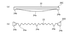
例えば、上記では、弾性率が異なる樹脂材料を用いることでスペーサ20Aの低ばね定数凸部24aおよび高ばね定数凸部24bを構成する例について説明したが、これに限定されるものでない。図4(a)に示すスペーサ20Cのように、低ばね定数凸部24aが、幅方向に湾曲して延びる皿ばね状または板ばね状に形成されてもよい。また、図4(b)に示すスペーサ20Dのように、ベース部23を波板状に形成し、ベース部23に含まれる多数の突出部のうちの例えば3つの突出部の高さを大きくすることによって、低ばね定数凸部24aを構成してもよい。
For example, in the above, an example in which the low spring constant
また、上記においてはスペーサ20Aのベース部22の一方側表面に低ばね定数凸部24aおよび高ばね定数凸部24bを設ける例について説明したが、ベース部22の配列方向Xの両側表面に各凸部24a,24bを設けてもよい。
In the above description, an example in which the low spring constant
さらに、上記においては低ばね定数凸部24aと高ばね定数凸部24bとの間に段差dを設けて低ばね定数凸部24aが先につぶれる構成としたが、これに限定されるものではない。低ばね定数凸部24aおよび高ばね定数凸部24bの各先端面が同一平面上となるように構成してもよい。
Further, in the above description, the step d is provided between the low spring constant
1 電池セル、2 電池ケース、2a,2b (電池ケースの)側壁、3 電極捲回体、4 正極端子、5 負極端子、10 バッテリ、12a,12b エンドプレート(拘束手段)、14 拘束バンド(拘束手段)、20A,20B,20C,20D スペーサ、22,23 ベース部、24a 低ばね定数凸部、24b 高ばね定数凸部、26 空間、d 段差、F1 拘束荷重、k1 高ばね定数、k2 低ばね定数、P1,P2,P3 面圧、y つぶれ量。
DESCRIPTION OF
Claims (1)
一方向に沿って配列された前記各電池セル間に介在されているスペーサと、
前記複数の電池セルおよび前記スペーサに対して前記一方向に沿って拘束荷重を付与する拘束手段と、を備えるバッテリであって、
前記電池ケースは可撓性の側壁を有し、前記スペーサは前記側壁に当接する低ばね定数凸部および高ばね定数凸部を含んでおり、前記スペーサの低ばね定数凸部は前記電池ケース内の前記電極捲回体に対向する位置で前記側壁に当接し、前記スペーサの高ばね定数凸部は前記電池ケース内の前記電極捲回体に対向しない位置で前記側壁に当接し、
前記低ばね定数凸部と前記高ばね定数凸部の夫々は、前記電池セルの高さ方向に沿って延伸する細長い直方体状をなしていて、前記電池ケースの側壁に当接する先端面が細長い長方形状をなしており、
前記スペーサが自然状態にあって押圧力が作用していないとき、前記低ばね定数凸部の突出長さが前記高ばね定数凸部の突出長さよりも長くなっている、バッテリ。 A plurality of battery cells each constituted by accommodating an electrode winding body in which a positive electrode and a negative electrode are wound in a flat shape with a separator interposed therebetween in a flat box-shaped battery case,
A spacer interposed between the battery cells arranged along one direction,
A battery comprising: a plurality of battery cells and a restraint unit that applies a restraint load to the spacer along the one direction,
The battery case has a flexible side wall, the spacer includes a low spring constant convex portion and a high spring constant convex portion that are in contact with the side wall, and the low spring constant convex portion of the spacer is inside the battery case. the electrode winding body abutting said side wall at a position opposed to a high spring constant protrusion of the spacer is abutted against the side wall at a position not opposed to the electrode winding body within the battery case,
Each of the low spring constant convex portion and the high spring constant convex portion has an elongated rectangular parallelepiped shape extending along the height direction of the battery cell, and a tip end surface abutting the side wall of the battery case is an elongated rectangle. In the shape of
When said spacer is not acting pressing force is in a natural state, the that have protruding length of the low spring constant projections longer than the projection length of the high spring constant protrusion, battery.
Priority Applications (1)
| Application Number | Priority Date | Filing Date | Title |
|---|---|---|---|
| JP2016104972A JP6724552B2 (en) | 2016-05-26 | 2016-05-26 | Battery |
Applications Claiming Priority (1)
| Application Number | Priority Date | Filing Date | Title |
|---|---|---|---|
| JP2016104972A JP6724552B2 (en) | 2016-05-26 | 2016-05-26 | Battery |
Publications (2)
| Publication Number | Publication Date |
|---|---|
| JP2017212120A JP2017212120A (en) | 2017-11-30 |
| JP6724552B2 true JP6724552B2 (en) | 2020-07-15 |
Family
ID=60476881
Family Applications (1)
| Application Number | Title | Priority Date | Filing Date |
|---|---|---|---|
| JP2016104972A Active JP6724552B2 (en) | 2016-05-26 | 2016-05-26 | Battery |
Country Status (1)
| Country | Link |
|---|---|
| JP (1) | JP6724552B2 (en) |
Cited By (2)
| Publication number | Priority date | Publication date | Assignee | Title |
|---|---|---|---|---|
| KR20240130369A (en) | 2023-02-22 | 2024-08-29 | 평화오일씰공업주식회사 | Barrier sheet between battery cells and method for manufacturing the same |
| FR3160272A1 (en) | 2024-03-14 | 2025-09-19 | Stellantis Auto Sas | STRUCTURE FOR ASSEMBLING A PLURALITY OF BATTERY CELLS INTO A BATTERY MODULE |
Families Citing this family (20)
| Publication number | Priority date | Publication date | Assignee | Title |
|---|---|---|---|---|
| JP7004206B2 (en) * | 2017-12-22 | 2022-01-21 | トヨタ自動車株式会社 | Batteries assembled |
| JP7011776B2 (en) * | 2018-01-19 | 2022-01-27 | トヨタ自動車株式会社 | Batteries assembled |
| JP2019128979A (en) * | 2018-01-19 | 2019-08-01 | トヨタ自動車株式会社 | Battery module |
| US20210043896A1 (en) * | 2018-03-23 | 2021-02-11 | Gs Yuasa International Ltd. | Energy storage apparatus |
| WO2020017458A1 (en) * | 2018-07-18 | 2020-01-23 | 日立化成株式会社 | Battery module, battery module production method, and elastic body |
| JP7059882B2 (en) * | 2018-10-05 | 2022-04-26 | トヨタ自動車株式会社 | Battery module |
| DE102018221477A1 (en) * | 2018-12-12 | 2020-06-18 | Robert Bosch Gmbh | Battery module comprising a plurality of battery cells |
| DE102018221472A1 (en) * | 2018-12-12 | 2020-06-18 | Robert Bosch Gmbh | Battery module unit comprising a battery cell |
| JP7215270B2 (en) * | 2019-03-22 | 2023-01-31 | トヨタ自動車株式会社 | Case manufacturing method |
| JP7169523B2 (en) * | 2019-04-02 | 2022-11-11 | トヨタ自動車株式会社 | assembled battery |
| JP7192665B2 (en) * | 2019-06-03 | 2022-12-20 | トヨタ自動車株式会社 | Spacer material |
| CN113906615B (en) * | 2019-06-28 | 2024-04-23 | 三洋电机株式会社 | Power supply device, electric vehicle having the same, and power storage device |
| WO2020261729A1 (en) * | 2019-06-28 | 2020-12-30 | 三洋電機株式会社 | Power supply device, and electric vehicle and power storage device comprising power supply device |
| EP4040525B1 (en) | 2019-09-30 | 2024-12-18 | SANYO Electric Co., Ltd. | Battery pack |
| CN111106378A (en) * | 2020-01-15 | 2020-05-05 | 东莞市好开心智能科技有限公司 | High-temperature pressure formation cabinet |
| JPWO2021199547A1 (en) * | 2020-03-31 | 2021-10-07 | ||
| US12424698B2 (en) * | 2020-03-31 | 2025-09-23 | Sanyo Electric Co., Ltd. | Power supply device, electric vehicle comprising power supply device, and power storage device |
| EP4131596A4 (en) * | 2020-03-31 | 2024-03-20 | SANYO Electric Co., Ltd. | Power supply device, electric vehicle provided with power supply device, and power storage device |
| JP7700770B2 (en) * | 2022-10-19 | 2025-07-01 | トヨタ自動車株式会社 | Battery Module |
| CN118983537B (en) * | 2024-08-03 | 2025-05-16 | 深圳市坤泰精密机械有限公司 | Battery cell winding mechanism and battery cell winding method |
Family Cites Families (8)
| Publication number | Priority date | Publication date | Assignee | Title |
|---|---|---|---|---|
| JP2000048867A (en) * | 1998-07-31 | 2000-02-18 | Toyota Motor Corp | Battery pack |
| JP2013200940A (en) * | 2010-06-14 | 2013-10-03 | Toyota Motor Corp | Power storage device |
| US8865331B2 (en) * | 2010-06-16 | 2014-10-21 | Toyota Jidosha Kabushiki Kaisha | Secondary battery assembly |
| JP5585524B2 (en) * | 2011-04-27 | 2014-09-10 | トヨタ自動車株式会社 | Assembled battery and manufacturing method of assembled battery |
| JP5915403B2 (en) * | 2012-06-18 | 2016-05-11 | 株式会社Gsユアサ | Assembled battery |
| JP6352640B2 (en) * | 2014-01-24 | 2018-07-04 | 日立オートモティブシステムズ株式会社 | Battery module |
| JP6219775B2 (en) * | 2014-04-23 | 2017-10-25 | トヨタ自動車株式会社 | Power storage device |
| JP2017098107A (en) * | 2015-11-25 | 2017-06-01 | トヨタ自動車株式会社 | Power storage device |
-
2016
- 2016-05-26 JP JP2016104972A patent/JP6724552B2/en active Active
Cited By (2)
| Publication number | Priority date | Publication date | Assignee | Title |
|---|---|---|---|---|
| KR20240130369A (en) | 2023-02-22 | 2024-08-29 | 평화오일씰공업주식회사 | Barrier sheet between battery cells and method for manufacturing the same |
| FR3160272A1 (en) | 2024-03-14 | 2025-09-19 | Stellantis Auto Sas | STRUCTURE FOR ASSEMBLING A PLURALITY OF BATTERY CELLS INTO A BATTERY MODULE |
Also Published As
| Publication number | Publication date |
|---|---|
| JP2017212120A (en) | 2017-11-30 |
Similar Documents
| Publication | Publication Date | Title |
|---|---|---|
| JP6724552B2 (en) | Battery | |
| CN110024211B (en) | Case for battery cell and battery module including the case | |
| KR101894652B1 (en) | Battery pack | |
| JP4547886B2 (en) | Assembled battery | |
| KR101392799B1 (en) | Battery Module Having Structure of Improved Stability and High Cooling Efficiency | |
| JP2017098107A (en) | Power storage device | |
| KR101150247B1 (en) | Battery module having flexibility in designing structure of module and battery pack employed with the same | |
| CN113994534B (en) | Electric storage module and method of manufacturing electric storage module | |
| CN108140769B (en) | Elastic plate and battery cell assembly including the elastic plate | |
| JP7037720B2 (en) | How to manufacture an assembled battery and a cell used for the assembled battery | |
| KR102102101B1 (en) | Battery pack | |
| JP5510044B2 (en) | Battery pack | |
| JP5472059B2 (en) | Power storage device | |
| KR20170013005A (en) | Battery module, battery pack comprising the battery module and vehicle comprising the battery pack | |
| JP6852308B2 (en) | Batteries | |
| JP6157813B2 (en) | Assembled battery | |
| JP4980673B2 (en) | Power storage module | |
| KR20120053589A (en) | Battery module of improved stability | |
| CN112864525B (en) | Nonaqueous electrolyte secondary battery | |
| CN108292720A (en) | Elastic bellows and battery cell assemblies including elastic bellows | |
| KR20190012979A (en) | Battery module, battery pack and energy storage system comprising the same | |
| WO2018155506A1 (en) | Battery module | |
| WO2019021778A1 (en) | Battery module, and vehicle equipped with same | |
| JP5724921B2 (en) | Strength setting method for restraint mechanism and power storage device | |
| CN104137295A (en) | Electrical storage device |
Legal Events
| Date | Code | Title | Description |
|---|---|---|---|
| A621 | Written request for application examination |
Free format text: JAPANESE INTERMEDIATE CODE: A621 Effective date: 20190315 |
|
| A977 | Report on retrieval |
Free format text: JAPANESE INTERMEDIATE CODE: A971007 Effective date: 20191216 |
|
| A131 | Notification of reasons for refusal |
Free format text: JAPANESE INTERMEDIATE CODE: A131 Effective date: 20200107 |
|
| A521 | Request for written amendment filed |
Free format text: JAPANESE INTERMEDIATE CODE: A523 Effective date: 20200219 |
|
| TRDD | Decision of grant or rejection written | ||
| A01 | Written decision to grant a patent or to grant a registration (utility model) |
Free format text: JAPANESE INTERMEDIATE CODE: A01 Effective date: 20200526 |
|
| A61 | First payment of annual fees (during grant procedure) |
Free format text: JAPANESE INTERMEDIATE CODE: A61 Effective date: 20200608 |
|
| R151 | Written notification of patent or utility model registration |
Ref document number: 6724552 Country of ref document: JP Free format text: JAPANESE INTERMEDIATE CODE: R151 |