EP3832227A1 - Refrigeration cycle device - Google Patents
Refrigeration cycle device Download PDFInfo
- Publication number
- EP3832227A1 EP3832227A1 EP18927363.4A EP18927363A EP3832227A1 EP 3832227 A1 EP3832227 A1 EP 3832227A1 EP 18927363 A EP18927363 A EP 18927363A EP 3832227 A1 EP3832227 A1 EP 3832227A1
- Authority
- EP
- European Patent Office
- Prior art keywords
- heat exchanger
- refrigerant mixture
- azeotropic refrigerant
- refrigeration cycle
- cycle apparatus
- Prior art date
- Legal status (The legal status is an assumption and is not a legal conclusion. Google has not performed a legal analysis and makes no representation as to the accuracy of the status listed.)
- Withdrawn
Links
Images




Classifications
-
- F—MECHANICAL ENGINEERING; LIGHTING; HEATING; WEAPONS; BLASTING
- F25—REFRIGERATION OR COOLING; COMBINED HEATING AND REFRIGERATION SYSTEMS; HEAT PUMP SYSTEMS; MANUFACTURE OR STORAGE OF ICE; LIQUEFACTION SOLIDIFICATION OF GASES
- F25B—REFRIGERATION MACHINES, PLANTS OR SYSTEMS; COMBINED HEATING AND REFRIGERATION SYSTEMS; HEAT PUMP SYSTEMS
- F25B13/00—Compression machines, plants or systems, with reversible cycle
-
- F—MECHANICAL ENGINEERING; LIGHTING; HEATING; WEAPONS; BLASTING
- F25—REFRIGERATION OR COOLING; COMBINED HEATING AND REFRIGERATION SYSTEMS; HEAT PUMP SYSTEMS; MANUFACTURE OR STORAGE OF ICE; LIQUEFACTION SOLIDIFICATION OF GASES
- F25B—REFRIGERATION MACHINES, PLANTS OR SYSTEMS; COMBINED HEATING AND REFRIGERATION SYSTEMS; HEAT PUMP SYSTEMS
- F25B47/00—Arrangements for preventing or removing deposits or corrosion, not provided for in another subclass
- F25B47/02—Defrosting cycles
-
- F—MECHANICAL ENGINEERING; LIGHTING; HEATING; WEAPONS; BLASTING
- F25—REFRIGERATION OR COOLING; COMBINED HEATING AND REFRIGERATION SYSTEMS; HEAT PUMP SYSTEMS; MANUFACTURE OR STORAGE OF ICE; LIQUEFACTION SOLIDIFICATION OF GASES
- F25B—REFRIGERATION MACHINES, PLANTS OR SYSTEMS; COMBINED HEATING AND REFRIGERATION SYSTEMS; HEAT PUMP SYSTEMS
- F25B1/00—Compression machines, plants or systems with non-reversible cycle
-
- F—MECHANICAL ENGINEERING; LIGHTING; HEATING; WEAPONS; BLASTING
- F25—REFRIGERATION OR COOLING; COMBINED HEATING AND REFRIGERATION SYSTEMS; HEAT PUMP SYSTEMS; MANUFACTURE OR STORAGE OF ICE; LIQUEFACTION SOLIDIFICATION OF GASES
- F25B—REFRIGERATION MACHINES, PLANTS OR SYSTEMS; COMBINED HEATING AND REFRIGERATION SYSTEMS; HEAT PUMP SYSTEMS
- F25B49/00—Arrangement or mounting of control or safety devices
- F25B49/02—Arrangement or mounting of control or safety devices for compression type machines, plants or systems
-
- F—MECHANICAL ENGINEERING; LIGHTING; HEATING; WEAPONS; BLASTING
- F25—REFRIGERATION OR COOLING; COMBINED HEATING AND REFRIGERATION SYSTEMS; HEAT PUMP SYSTEMS; MANUFACTURE OR STORAGE OF ICE; LIQUEFACTION SOLIDIFICATION OF GASES
- F25B—REFRIGERATION MACHINES, PLANTS OR SYSTEMS; COMBINED HEATING AND REFRIGERATION SYSTEMS; HEAT PUMP SYSTEMS
- F25B5/00—Compression machines, plants or systems, with several evaporator circuits, e.g. for varying refrigerating capacity
- F25B5/02—Compression machines, plants or systems, with several evaporator circuits, e.g. for varying refrigerating capacity arranged in parallel
-
- F—MECHANICAL ENGINEERING; LIGHTING; HEATING; WEAPONS; BLASTING
- F25—REFRIGERATION OR COOLING; COMBINED HEATING AND REFRIGERATION SYSTEMS; HEAT PUMP SYSTEMS; MANUFACTURE OR STORAGE OF ICE; LIQUEFACTION SOLIDIFICATION OF GASES
- F25B—REFRIGERATION MACHINES, PLANTS OR SYSTEMS; COMBINED HEATING AND REFRIGERATION SYSTEMS; HEAT PUMP SYSTEMS
- F25B6/00—Compression machines, plants or systems, with several condenser circuits
- F25B6/02—Compression machines, plants or systems, with several condenser circuits arranged in parallel
-
- F—MECHANICAL ENGINEERING; LIGHTING; HEATING; WEAPONS; BLASTING
- F25—REFRIGERATION OR COOLING; COMBINED HEATING AND REFRIGERATION SYSTEMS; HEAT PUMP SYSTEMS; MANUFACTURE OR STORAGE OF ICE; LIQUEFACTION SOLIDIFICATION OF GASES
- F25B—REFRIGERATION MACHINES, PLANTS OR SYSTEMS; COMBINED HEATING AND REFRIGERATION SYSTEMS; HEAT PUMP SYSTEMS
- F25B2313/00—Compression machines, plants or systems with reversible cycle not otherwise provided for
- F25B2313/021—Indoor unit or outdoor unit with auxiliary heat exchanger not forming part of the indoor or outdoor unit
- F25B2313/0213—Indoor unit or outdoor unit with auxiliary heat exchanger not forming part of the indoor or outdoor unit the auxiliary heat exchanger being only used during heating
-
- F—MECHANICAL ENGINEERING; LIGHTING; HEATING; WEAPONS; BLASTING
- F25—REFRIGERATION OR COOLING; COMBINED HEATING AND REFRIGERATION SYSTEMS; HEAT PUMP SYSTEMS; MANUFACTURE OR STORAGE OF ICE; LIQUEFACTION SOLIDIFICATION OF GASES
- F25B—REFRIGERATION MACHINES, PLANTS OR SYSTEMS; COMBINED HEATING AND REFRIGERATION SYSTEMS; HEAT PUMP SYSTEMS
- F25B2313/00—Compression machines, plants or systems with reversible cycle not otherwise provided for
- F25B2313/023—Compression machines, plants or systems with reversible cycle not otherwise provided for using multiple indoor units
- F25B2313/0234—Compression machines, plants or systems with reversible cycle not otherwise provided for using multiple indoor units in series arrangements
-
- F—MECHANICAL ENGINEERING; LIGHTING; HEATING; WEAPONS; BLASTING
- F25—REFRIGERATION OR COOLING; COMBINED HEATING AND REFRIGERATION SYSTEMS; HEAT PUMP SYSTEMS; MANUFACTURE OR STORAGE OF ICE; LIQUEFACTION SOLIDIFICATION OF GASES
- F25B—REFRIGERATION MACHINES, PLANTS OR SYSTEMS; COMBINED HEATING AND REFRIGERATION SYSTEMS; HEAT PUMP SYSTEMS
- F25B2313/00—Compression machines, plants or systems with reversible cycle not otherwise provided for
- F25B2313/029—Control issues
- F25B2313/0294—Control issues related to the outdoor fan, e.g. controlling speed
-
- F—MECHANICAL ENGINEERING; LIGHTING; HEATING; WEAPONS; BLASTING
- F25—REFRIGERATION OR COOLING; COMBINED HEATING AND REFRIGERATION SYSTEMS; HEAT PUMP SYSTEMS; MANUFACTURE OR STORAGE OF ICE; LIQUEFACTION SOLIDIFICATION OF GASES
- F25B—REFRIGERATION MACHINES, PLANTS OR SYSTEMS; COMBINED HEATING AND REFRIGERATION SYSTEMS; HEAT PUMP SYSTEMS
- F25B2313/00—Compression machines, plants or systems with reversible cycle not otherwise provided for
- F25B2313/031—Sensor arrangements
- F25B2313/0315—Temperature sensors near the outdoor heat exchanger
-
- F—MECHANICAL ENGINEERING; LIGHTING; HEATING; WEAPONS; BLASTING
- F25—REFRIGERATION OR COOLING; COMBINED HEATING AND REFRIGERATION SYSTEMS; HEAT PUMP SYSTEMS; MANUFACTURE OR STORAGE OF ICE; LIQUEFACTION SOLIDIFICATION OF GASES
- F25B—REFRIGERATION MACHINES, PLANTS OR SYSTEMS; COMBINED HEATING AND REFRIGERATION SYSTEMS; HEAT PUMP SYSTEMS
- F25B2600/00—Control issues
- F25B2600/25—Control of valves
- F25B2600/2515—Flow valves
Definitions
- the present invention relates to a refrigeration cycle apparatus in which a non-azeotropic refrigerant mixture is used.
- a non-azeotropic refrigerant mixture is sometimes used that is reduced in global warming potential (GWP) by mixing refrigerant made of a single component with another refrigerant having a lower GWP.
- GWP global warming potential
- WO2015/151289 discloses an air conditioning apparatus in which a non-azeotropic refrigerant mixture such as R-407C can be used.
- a heat source-side heat exchanger includes a first heat exchange unit and a second heat exchange unit.
- the flow rate of the heat medium circulating through the first heat exchange unit is reduced, thereby allowing a defrosting ability to be uniformly achieved in the entire region of the heat source-side heat exchanger.
- a non-azeotropic refrigerant mixture has a characteristic (a temperature gradient) that, at constant pressure, the non-azeotropic refrigerant mixture existing as saturated vapor is higher in temperature than the non-azeotropic refrigerant mixture existing as a saturated liquid.
- the non-azeotropic refrigerant mixture flowing into a heat exchanger functioning as an evaporator is lower in temperature than the non-azeotropic refrigerant mixture flowing out of this heat exchanger.
- frost is more likely to be formed near a port of the heat exchanger into which the non-azeotropic refrigerant mixture flows.
- the air conditioning apparatus disclosed in PTL 1 no consideration is given to the temperature decrease near the port of the heat exchanger into which the non-azeotropic refrigerant mixture flows.
- An object of the present invention is to suppress performance deterioration caused by formation of frost on a heat exchanger in a refrigeration cycle apparatus in which a non-azeotropic refrigerant mixture is used.
- a non-azeotropic refrigerant mixture is used.
- the refrigeration cycle apparatus includes a compressor, a first heat exchanger, a decompressor, a second heat exchanger, a third heat exchanger, and a blower.
- the blower is configured to blow air to the second heat exchanger and the third heat exchanger.
- the non-azeotropic refrigerant mixture circulates in a first circulation direction through the compressor, the first heat exchanger, the decompressor, the second heat exchanger, and the third heat exchanger.
- the second heat exchanger is greater in flow path resistance than the third heat exchanger.
- the blower is configured to form a parallel flow with the non-azeotropic refrigerant mixture flowing through the second heat exchanger and the third heat exchanger.
- the second heat exchanger is greater in flow path resistance than the third heat exchanger, and the blower forms a parallel flow with the non-azeotropic refrigerant mixture flowing through the second heat exchanger and the third heat exchanger, thereby allowing suppression of formation of frost on the second heat exchanger and the third heat exchanger.
- the performance deterioration caused by formation of frost on a heat exchanger can be suppressed.
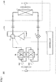
- Fig. 1 is a functional block diagram showing a configuration of a refrigeration cycle apparatus 100 according to the first embodiment together with the flow of a non-azeotropic refrigerant mixture in a heating operation.
- Refrigeration cycle apparatus 100 may be a package air conditioner (PAC) or a room air conditioner (RAC), for example.
- PAC package air conditioner
- RAC room air conditioner
- refrigeration cycle apparatus 100 includes an outdoor unit 110 and an indoor unit 120.
- Outdoor unit 110 includes a compressor 1, a four-way valve 2 (a flow path switching valve), an expansion valve 4 (a decompressor), a heat exchanger 5a (a second heat exchanger), a heat exchanger 5b (a third heat exchanger), an outdoor fan 7 (a blower), and a controller 8.
- Indoor unit 120 includes a heat exchanger 3 (a first heat exchanger) and an indoor fan 6.
- a non-azeotropic refrigerant mixture is used that is reduced in GWP as compared with the conventionally used refrigerant (for example, R404A or R410A).
- the non-azeotropic refrigerant mixture includes R32 and has a temperature gradient of 3 degrees or more at standard atmospheric pressure.
- the weight ratio of HFC32 is desirably set at 46 wt% or less.
- the weight ratio of HFC32 set at 46 wt% or less allows the GWP of the non-azeotropic refrigerant mixture to be reduced to about 300.
- the regulations for refrigerant for example, the Montreal Protocol or the F-gas regulations
- HFC32 raises the operating pressure of the non-azeotropic refrigerant mixture.
- HFC32 is contained in the non-azeotropic refrigerant mixture to thereby allow reduction of the volume (stroke volume) of compressor 1 that is required for ensuring desired operating pressure, with the result that compressor 1 can be reduced in size.
- the refrigerant contained in the non-azeotropic refrigerant mixture in addition to HFC32 is refrigerant (for example, R1234yf, R1234ze(E), R290, or CO2) that is lower in GWP than the conventionally used refrigerant.
- the non-azeotropic refrigerant mixture may contain refrigerant (for example, R134a or R125) that is higher in GWP than the conventionally used refrigerant.
- the non-azeotropic refrigerant mixture may also contain three or more types of refrigerant.
- Controller 8 controls the driving frequency of compressor 1 to thereby control the amount of refrigerant discharged from compressor 1 per unit time such that the temperature inside indoor unit 120 measured by a temperature sensor (not shown) reaches a desired temperature (for example, the temperature set by a user). Controller 8 controls the degree of opening of expansion valve 4 such that the degree of superheating or the degree of supercooling of the non-azeotropic refrigerant mixture attains a value in a desired range. Controller 8 controls the amount of air blown from each of indoor fan 6 and outdoor fan 7 per unit time such that the temperature in indoor unit 120 reaches a desired temperature.
- Controller 8 controls the amount of air blown from indoor fan 6 per unit time while prioritizing the user's setting (for example, a weak wind mode or a strong wind mode) for indoor fan 6. Controller 8 controls four-way valve 2 to switch the direction in which the non-azeotropic refrigerant mixture circulates. In addition, in accordance with the temperature difference between the discharge temperature of compressor 1 and the heat-resistance temperature (for example, 100 °C) of compressor 1 that has been set in advance, controller 8 may adjust the driving frequency of compressor 1, the amount of air blown from each of indoor fan 6 and outdoor fan 7 per unit time, and the degree of opening of expansion valve 4.
- Controller 8 controls four-way valve 2 to allow, in the heating operation, communication between the discharge port of compressor 1 and heat exchanger 3, and communication between heat exchanger 5b and the suction port of compressor 1.
- the non-azeotropic refrigerant mixture circulates in a circulation direction (the first circulation direction) through compressor 1, four-way valve 2, heat exchanger 3, expansion valve 4, heat exchanger 5a, heat exchanger 5b, and four-way valve 2.
- Heat exchangers 5a and 5b are connected in series between expansion valve 4 and four-way valve 2. Heat exchanger 5a is greater in flow path resistance than heat exchanger 5b. In other words, the pressure loss in heat exchanger 5a is greater than the pressure loss in heat exchanger 5b.
- heat exchanger 5a includes at least one heat transfer tube formed so as to extend in parallel
- heat exchanger 5b includes a plurality of heat transfer tubes formed so as to extend in parallel. The number of heat transfer tubes in heat exchanger 5a is less than the number of heat transfer tubes in heat exchanger 5b.
- heat exchanger 5a includes two heat transfer tubes and heat exchanger 5b includes four heat transfer tubes, but the number of heat transfer tubes included in each of heat exchangers 5a and 5b is not limited to the number shown in Fig. 1 .
- the non-azeotropic refrigerant mixture exchanges heat with air while it flows through the heat transfer tubes included in heat exchangers 5a and 5b.
- Outdoor fan 7 blows air to heat exchangers 5a and 5b to form a parallel flow with the non-azeotropic refrigerant mixture that flows through heat exchangers 5a and 5b.
- Heat exchangers 5a and 5b are disposed to extend in the direction orthogonal to an air blowing direction Ad1 of the blower. In Fig.
- connection pipe is formed such that the non-azeotropic refrigerant mixture flowing out of heat exchanger 5a and the non-azeotropic refrigerant mixture flowing out of heat exchanger 5b join each other and flow toward heat exchanger 5b, but the manner of the connection pipe that connects heat exchangers 5a and 5b is not limited to the manner of connection shown in Fig. 1 .
- the connection pipe may be formed such that the non-azeotropic refrigerant mixtures flowing out of heat exchangers 5a and 5b flow toward heat exchanger 5b without joining each other.
- each of the heat transfer tubes included in heat exchangers 5a and 5b is formed to extend in a straight line from one port to the other port, but may be formed to meander from one port to the other port.
- Heat exchanger 5a may be different in structure (for example, the pitch in the column direction, the pitch in the row direction, or the pitch of fins) from heat exchanger 5b.
- a distribution device or a distributor may be provided between heat exchangers 5a and 5b.
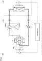
- Fig. 2 is a functional block diagram showing the configuration of refrigeration cycle apparatus 100 in Fig. 1 together with the flow of the non-azeotropic refrigerant mixture in a cooling operation and a defrosting operation.
- controller 8 controls four-way valve 2 to allow, in the cooling operation and the defrosting operation, communication between the discharge port of compressor 1 and heat exchanger 5b, and communication between heat exchanger 3 and the suction port of compressor 1.
- the non-azeotropic refrigerant mixture circulates in a circulation direction (in the second circulation direction) through compressor 1, four-way valve 2, heat exchanger 5b, heat exchanger 5a, expansion valve 4, heat exchanger 3, and four-way valve 2.
- controller 8 controls four-way valve 2 to switch the circulation direction of the non-azeotropic refrigerant mixture so as to start the defrosting operation. After the defrosting completion time has passed since the start of the defrosting operation, controller 8 ends the defrosting operation and resumes the heating operation.
- a threshold value for example, -2°C
- controller 8 stops the indoor fan to prevent the air cooled by heat exchanger 3 functioning as an evaporator from being blown into a room. Controller 8 stops outdoor fan 7 or reduces the amount of air blown from outdoor fan 7 per unit time to thereby suppress heat exchange between air and the non-azeotropic refrigerant mixture that flows through heat exchangers 5a and 5b so as to facilitate melting of frost by sensible heat and latent heat of the non-azeotropic refrigerant mixture.
- outdoor fan 7 blows air in air blowing direction Ad1 as in the heating operation.
- the direction in which the non-azeotropic refrigerant mixture flows through heat exchangers 5a and 5b is opposite to that in the heating operation.
- a counterflow is formed by the non-azeotropic refrigerant mixture flowing through heat exchangers 5a and 5b, and the air blown from outdoor fan 7.
- Heat exchangers 4a and 5b each function as an evaporator in the heating operation, and function as a condenser in the cooling operation and the defrosting operation.
- the state of the non-azeotropic refrigerant mixture changes in the condensation process in a condenser in the order of: gas having a degree of superheating; a gas-liquid two-phase state; and a liquid having a degree of supercooling.
- the state of the non-azeotropic refrigerant mixture is almost in a gas-liquid two-phase state.
- the temperature of the non-azeotropic refrigerant mixture changes more greatly in the condensation process than in the evaporation process.
- air blowing direction Ad1 of outdoor fan 7 is defined such that air blowing direction Ad1 of outdoor fan 7 and the direction of the non-azeotropic refrigerant mixture flowing through heat exchangers 5a, 5b form a parallel flow in the heating operation and form a counterflow in the cooling operation.
- air blowing direction Ad1 in this way, the heat exchange efficiency of heat exchangers 5a and 5b in the cooling operation can be improved while suppressing deterioration in heat exchange efficiency of heat exchangers 5a and 5b in the heating operation.
- Fig. 3 is a diagram showing a configuration of a refrigeration cycle apparatus 900 according to a comparative example together with the flow of the non-azeotropic refrigerant mixture in the heating operation.
- Refrigeration cycle apparatus 900 has the same configuration as that of refrigeration cycle apparatus 100 in Fig. 1 except that heat exchangers 5a and 5b in refrigeration cycle apparatus 100 are replaced with a heat exchanger 5. Since the configuration other than the above is the same, the description thereof will not be repeated.
- Fig. 4 is a P-h diagram showing the relation among enthalpy, pressure, and a temperature of the non-azeotropic refrigerant mixture in refrigeration cycle apparatus 900 in Fig. 3 .
- curved lines LC and GC show a saturated liquid line and a saturated vapor line, respectively.
- the saturated liquid line and the saturated vapor line are connected to each other at a critical point CP.
- Fig. 6 which will be described later.
- the process from a state C1 to a state C2 shows the adiabatic compression process by compressor 1.
- the process from state C2 to a state C3 shows the condensation process by heat exchanger 3.
- the process from state C3 to a state C4 shows the decompression process by expansion valve 4.
- the process from state C4 to state C1 shows the evaporation process by heat exchanger 5.
- Fig. 5 is a diagram showing: a correspondence relation R1 between the position in a certain heat transfer tube of heat exchanger 5 in Fig. 3 and the temperature of the non-azeotropic refrigerant mixture at this position; and a correspondence relation A1 between this position and the temperature of air at this position.
- a position L1 shows the position of the port of heat exchanger 5 through which a non-azeotropic refrigerant mixture flows in.
- a position L92 shows the position of the port of heat exchanger 5 through which a non-azeotropic refrigerant mixture flows out.
- a temperature T1 shows the temperature in state C4 in Fig. 4 .
- a temperature T2 shows the temperature in state C1 in Fig. 4 .
- the non-azeotropic refrigerant mixture flowing from position L1 into heat exchanger 5 absorbs heat from air in the process in which the non-azeotropic refrigerant mixture flows from position L1 to position L2. As a result, the temperature of the non-azeotropic refrigerant mixture rises from T1 to T2.
- the air blown by outdoor fan 7 to heat exchanger 5 is deprived of heat due to absorption by the non-azeotropic refrigerant mixture flowing through heat exchanger 5 in the process in which the air flows from position L1 to position L2. As a result, the temperature of the air lowers from T3 to T4.
- the temperature of the non-azeotropic refrigerant mixture suctioned by compressor 1 is approximately constant. Accordingly, as the temperature gradient of the non-azeotropic refrigerant mixture becomes larger, temperature T4 of the non-azeotropic refrigerant mixture flowing into heat exchanger 5 becomes lower, and thereby, frost is more likely to be formed on heat exchanger 5. As a result, the performance of refrigeration cycle apparatus 900 may deteriorate.
- heat exchangers 5a and 5b connected in series each are caused to function as an evaporator in the heating operation.
- the flow path resistance of heat exchanger 5a is set to be greater than the flow path resistance of heat exchanger 5b.
- the temperature of the non-azeotropic refrigerant mixture suctioned by heat exchanger 5a can be set to be higher than T1 while the temperature of the non-azeotropic refrigerant mixture suctioned by compressor 1 can be maintained at T2.
- formation of frost on heat exchangers 5a and 5b each functioning as an evaporator can be suppressed while maintaining the performance.
- the frequency of the defrosting operation can be reduced, the comfortableness for users can be improved.
- Fig. 6 is a P-h diagram showing the relation among enthalpy, pressure, and a temperature of the non-azeotropic refrigerant mixture in refrigeration cycle apparatus 100 in Fig. 1 .
- states C1 to C3 are the same as those in Fig. 4 .
- the process from a state C14 to a state C15 shows the evaporation process by heat exchanger 5a.
- the process from state C15 to state C1 shows the evaporation process by heat exchanger 5b.
- the pressure loss in heat exchanger 5a causes the pressure of the non-azeotropic refrigerant mixture to decrease as the evaporation process progresses.
- the evaporation process from state C14 to state C15 changes along the isothermal line of temperature T14.
- the pressure loss in heat exchanger 5b is smaller than the pressure loss in heat exchanger 5a.
- the pressure decrease in the non-azeotropic refrigerant mixture is less than the pressure decrease in the evaporation process from state C14 to state C15.
- Fig. 7 is a diagram showing: correspondence relations R11 and R12 between the position in a certain heat transfer tube of heat exchangers 5a and 5b in Fig. 1 and the temperature of the non-azeotropic refrigerant mixture at this position; and correspondence relations A11 and A12 between this position and the temperature of air at this position.
- correspondence relation R11 shows the correspondence relation between the position in a certain heat transfer tube of heat exchanger 5a and the temperature of the non-azeotropic refrigerant mixture at this position.
- Correspondence relation A11 shows the correspondence relation between the position in a certain heat transfer tube of heat exchanger 5a and the temperature of air at this position.
- Correspondence relation R12 shows the correspondence relation between the position in a certain heat transfer tube of heat exchanger 5b and the temperature of the non-azeotropic refrigerant mixture at this position.
- Correspondence relation A12 shows the correspondence relation between the position in a certain heat transfer tube of heat exchanger 5b and the temperature of air at this position.
- a position L11 shows the position of the port of heat exchanger 5a through which the non-azeotropic refrigerant mixture flows in.
- a position L12 shows the position of the port of heat exchanger 5a through which the non-azeotropic refrigerant mixture flows out.
- a position L13 shows the position of the port of heat exchanger 5b through which the non-azeotropic refrigerant mixture flows in.
- Fig. 7 shows positions L12 and L13 that are superimposed on each other.
- a position L14 shows the position of the port of heat exchanger 5b through which the non-azeotropic refrigerant mixture flows out.
- Temperature T14 shows the temperature in state C14 in Fig. 6 .
- Temperature T15 shows the temperature in state C15 in Fig. 6 .
- Temperatures T1 to T3 are the same as those in Fig. 5 .
- the non-azeotropic refrigerant mixture flowing from position L11 into heat exchanger 5a absorbs heat from air in the process in which this non-azeotropic refrigerant mixture flows from position L11 to position L12. As a result, the temperature of the non-azeotropic refrigerant mixture rises from T14 to T15. Temperature T14 is higher than temperature T1. Also, the non-azeotropic refrigerant mixture flowing from position L13 into heat exchanger 5b absorbs heat from air in the process in which this non-azeotropic refrigerant mixture flows from position L13 to position L14. As a result, the temperature of the non-azeotropic refrigerant mixture rises from T15 to T2.
- the air blown by outdoor fan 7 to heat exchanger 5a is deprived of heat due to absorption by the non-azeotropic refrigerant mixture flowing through heat exchanger 5a in the process in which the air flows from position L11 to position L12.
- the temperature of the air lowers from T3 to T16.
- the air blown by outdoor fan 7 to heat exchanger 5b is deprived of heat due to absorption by the non-azeotropic refrigerant mixture flowing through heat exchanger 5b in the process in which the air flows from position L13 to position L14.
- the temperature of the air lowers from T3 to T17.
- heat exchangers 5a and 5b are disposed to extend in the direction orthogonal to air blowing direction Ad1.
- air blown to heat exchangers 5a and 5b has approximately the same temperature T3.
- the non-azeotropic refrigerant mixture flowing from position L13 into heat exchanger 5b can start exchanging of heat with air of the temperature that is approximately the same as temperature T3 of the air at position L11.
- the heat exchange efficiency of heat exchanger 5b can be improved as compared with the case where the non-azeotropic refrigerant mixture flowing into heat exchanger 5b continues exchanging of heat with the air having temperature T16 at position L12.
- Fig. 8 is a diagram showing the correspondence relation between: a ratio of the number of heat transfer tubes in heat exchanger 5b to the number of heat transfer tubes in heat exchanger 5a in Fig. 1 ; and a ratio of a coefficient of performance (COP) of refrigeration cycle apparatus 100 in Fig. 1 to a COP of refrigeration cycle apparatus 900 in Fig. 3 .
- the ratio of the number of heat transfer tubes in heat exchanger 5b to the number of heat transfer tubes in heat exchanger 5a is 2 or more
- the ratio of the coefficient of performance (COP) of refrigeration cycle apparatus 100 in Fig. 1 to the COP of refrigeration cycle apparatus 900 is 1 or more.
- the number of heat transfer tubes in heat exchanger 5b is equal to or greater than two times as large as the number of heat transfer tubes in heat exchanger 5a.
- Fig. 9 is a functional block diagram showing a configuration of a refrigeration cycle apparatus 100A according to the first modification of the first embodiment.
- Refrigeration cycle apparatus 100A has the same configuration as that of refrigeration cycle apparatus 100 in Fig. 1 except that it additionally includes a heat exchanger 5c. Since the configuration other than the above is the same, the description thereof will not be repeated.
- heat exchanger 5c is connected between heat exchangers 5a and 5b.
- Heat exchanger 5c is smaller in flow path resistance than heat exchanger 5a, and greater in flow path resistance than heat exchanger 5b.
- Heat exchanger 5c includes a plurality of heat transfer tubes formed so as to extend in parallel with each other. The number of heat transfer tubes in heat exchanger 5c is greater than the number of heat transfer tubes in heat exchanger 5a and less than the number of heat transfer tubes in heat exchanger 5b.
- Heat exchangers 5a to 5c are disposed to extend in the direction orthogonal to air blowing direction Ad1.
- Fig. 10 is a functional block diagram showing a configuration of a refrigeration cycle apparatus 100B according to the second modification of the first embodiment.
- Refrigeration cycle apparatus 100B has the same configuration as that of refrigeration cycle apparatus 100 in Fig. 1 except that heat exchangers 5a and 5b are disposed to extend in air blowing direction Ad1. Since the configuration other than the above is the same, the description thereof will not be repeated.
- the first embodiment has been described with regard to the configuration including a flow path switching valve.
- the refrigeration cycle apparatus according to the present embodiment may also have a configuration not including a flow path switching valve, like a showcase or a refrigerator.
- Fig. 11 is a functional block diagram showing a configuration of a refrigeration cycle apparatus 100C according to the third modification of the first embodiment.
- Refrigeration cycle apparatus 100C has the same configuration as that of refrigeration cycle apparatus 100 in Fig. 1 except that four-way valve 2 is removed and controller 8 is replaced with a controller 8C. Since the configuration other than the above is the same, the description thereof will not be repeated.
- controller 8C stops compressor 1 and thereafter causes a heater (not shown) to heat the heat exchangers 5a and 5b. After the defrosting completion time has passed since the start of the heater, controller 8C stops the heater and restarts compressor 1.
- the first embodiment has been described with regard to the refrigeration cycle apparatus including one outdoor unit and one indoor unit.
- the refrigeration cycle apparatus according to the present embodiment may include a plurality of outdoor units and may include a plurality of indoor units.
- the refrigeration cycle apparatus can suppress the performance deterioration caused by frost formed on heat exchangers.
- the second embodiment will be described with regard to the configuration in which air exchanging heat with two heat exchangers each functioning as an evaporator is heated by another heat exchanger so as to further suppress formation of frost as compared with the first embodiment.
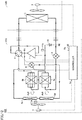
- Fig. 12 is a functional block diagram showing a configuration of a refrigeration cycle apparatus 200 according to the second embodiment together with the flow of the non-azeotropic refrigerant mixture in the heating operation.
- Refrigeration cycle apparatus 200 has the same configuration as that of refrigeration cycle apparatus 100 in Fig. 1 except that it additionally includes a heat exchanger 5d (a fourth heat exchanger), a heat exchanger 5e (a fifth heat exchanger), a flow rate regulating valve 9 (an on-off valve), a check valve 10, and temperature sensors 11a and 11b, and that controller 8 is replaced with a controller 28. Since the configuration other than the above is the same, the description thereof will not be repeated.
- flow rate regulating valve 9 is connected to a connection node N1 between the discharge port of compressor 1 and four-way valve 2.
- Check valve 10 is connected to a connection node N2 between expansion valve 4 and heat exchanger 3.
- the forward direction of check valve 10 corresponds to the direction from check valve 10 to connection node N2.
- Heat exchangers 5d and 5e are connected in this order in series between flow rate regulating valve 9 and check valve 10. Heat exchangers 5d and 5a are disposed in this order to extend adjacent to each other in air blowing direction Ad1. Heat exchangers 5e and 5b are disposed in this order to extend adjacent to each other in air blowing direction Ad1.
- heat exchangers 5a, 5b, 5d, and 5e may be different in structure (for example, the pitch in the column direction, the pitch in the row direction, or the pitch of fins) from one another. Furthermore, it is preferable that the pitch in the row direction in each of heat exchangers 5d and 5e is set to be longer than the pitch in the row direction in each of heat exchangers 5a and 5b, thereby setting the heating distance in each of heat exchangers 5d and 5e to be longer than the heating distance in each of heat exchangers 5a and 5b.
- the pitch of the fins in each of heat exchangers 5d and 5e is set to be larger than the pitch of the fins in each of heat exchangers 5a and 5b, thereby setting the ventilation resistance in each of heat exchangers 5d and 5e to be lower than the ventilation resistance in each of heat exchangers 5a and 5b. It is preferable that the volume of heat exchanger 5a is equal to or less than 20% of the total volume of heat exchangers 5a and 5b.
- Controller 28 opens flow rate regulating valve 9 in the heating operation.
- part of the non-azeotropic refrigerant mixture discharged from compressor 1 passes through heat exchangers 5d and 5e.
- Heat exchangers 5d and 5e each function as a condenser.
- the air blown by outdoor fan 7 is heated by the condensation heat from the non-azeotropic refrigerant mixture that passes through heat exchanger 5d. This air exchanges heat with the non-azeotropic refrigerant mixture that passes through heat exchanger 5a.
- the air blown by outdoor fan 7 is heated by the condensation heat from the non-azeotropic refrigerant mixture that passes through heat exchanger 5e. This air exchanges heat with the non-azeotropic refrigerant mixture that passes through heat exchanger 5b.
- controller 28 From a temperature sensor 11a, controller 28 obtains a temperature Ta of the non-azeotropic refrigerant mixture that flows into heat exchanger 5e. From a temperature sensor 1 1b, controller 28 obtains a temperature Tb of the non-azeotropic refrigerant mixture that flows out of heat exchanger 5e. Controller 28 adjusts the degree of opening of flow rate regulating valve 9 such that the difference between temperatures Ta and Tb fall within a prescribed range. By the control as described above, the state of the non-azeotropic refrigerant mixture that passes through check valve 10 turns into a supercooled state, like the non-azeotropic refrigerant mixture that flows out of heat exchanger 3. The temperature of the non-azeotropic refrigerant mixture that flows out of heat exchanger 3 may be used in place of temperature Tb.
- the air exchanging heat with heat exchanger 5a is heated by heat exchanger 5d while the air exchanging heat with heat exchanger 5b is heated by heat exchanger 5e.
- the temperature difference between air and the non-azeotropic refrigerant mixture in heat exchangers 5a and 5b can be maintained at approximately the same temperature difference between air and the non-azeotropic refrigerant mixture in heat exchangers 5a and 5b in refrigeration cycle apparatus 100 in Fig. 1 .
- formation of frost on heat exchangers 5a and 5b can be further suppressed.
- Fig. 13 is a functional block diagram showing the configuration of refrigeration cycle apparatus 200 according to the second embodiment together with the flow of the non-azeotropic refrigerant mixture in the cooling operation and the defrosting operation.
- controller 28 closes flow rate regulating valve 9 in the cooling operation and the defrosting operation.
- the pressure of the non-azeotropic refrigerant mixture in the flow path between flow rate regulating valve 9 and check valve 10 is approximately the same as the pressure of the non-azeotropic refrigerant mixture decompressed by expansion valve 4.
- the non-azeotropic refrigerant mixture evaporates, thereby increasing the ratio of the non-azeotropic refrigerant mixture in a gaseous state in the flow path between flow rate regulating valve 9 and check valve 10. Then, the non-azeotropic refrigerant mixture in a liquid state accumulated in heat exchangers 5c and 5d decreases. As a result, reduction of the amount of the non-azeotropic refrigerant mixture circulating through refrigeration cycle apparatus 200 can be suppressed.
- Fig. 12 an explanation has been given with regard to the case where the non-azeotropic refrigerant mixture discharged from compressor 1 passes through heat exchangers 5d and 5e in this order.
- the non-azeotropic refrigerant mixture For raising the temperature of the non-azeotropic refrigerant mixture that flows into heat exchanger 5a into which the non-azeotropic refrigerant mixture flows, it is preferable to cause the non-azeotropic refrigerant mixture to pass through heat exchangers 5d and 5e in this order so as to set the temperature of the non-azeotropic refrigerant mixture flowing into heat exchanger 5d adjacent to heat exchanger 5a to be higher than the temperature of the non-azeotropic refrigerant mixture flowing into heat exchanger 5e adjacent to heat exchanger 5b.
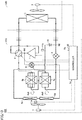
- a flow path may be formed so as to cause the non-azeotropic refrigerant mixture to pass through heat exchangers 5e and 5d in this order, as in refrigeration cycle apparatus 200A shown in Fig. 14 .
- the performance deterioration caused by frost formed on the heat exchangers can be further suppressed as compared with the refrigeration cycle apparatus according to the first embodiment.
- 1 compressor 2 four-way valve, 3, 5, 5a to 5e heat exchanger, 4 expansion valve, 6 indoor fan, 7 outdoor fan, 8, 8C, 28 controller, 9 flow rate regulating valve, 10 check valve, 11a, 11b temperature sensor, 100, 100A to 100C, 200, 200A, 900 refrigeration cycle apparatus, 110 outdoor unit, 120 indoor unit.
Landscapes
- Engineering & Computer Science (AREA)
- Physics & Mathematics (AREA)
- Mechanical Engineering (AREA)
- Thermal Sciences (AREA)
- General Engineering & Computer Science (AREA)
- Compression-Type Refrigeration Machines With Reversible Cycles (AREA)
Abstract
Description
- The present invention relates to a refrigeration cycle apparatus in which a non-azeotropic refrigerant mixture is used.
- From a viewpoint of global warming prevention, recently, in a refrigeration cycle apparatus, a non-azeotropic refrigerant mixture is sometimes used that is reduced in global warming potential (GWP) by mixing refrigerant made of a single component with another refrigerant having a lower GWP. For example,
WO2015/151289 (PTL 1) discloses an air conditioning apparatus in which a non-azeotropic refrigerant mixture such as R-407C can be used. In the air conditioning apparatus, a heat source-side heat exchanger includes a first heat exchange unit and a second heat exchange unit. When the outlet temperature of the first heat exchange unit is higher than the outlet temperature of the second heat exchange unit, the flow rate of the heat medium circulating through the first heat exchange unit is reduced, thereby allowing a defrosting ability to be uniformly achieved in the entire region of the heat source-side heat exchanger. - PTL 1:
WO2015/151289 - It is known that a non-azeotropic refrigerant mixture has a characteristic (a temperature gradient) that, at constant pressure, the non-azeotropic refrigerant mixture existing as saturated vapor is higher in temperature than the non-azeotropic refrigerant mixture existing as a saturated liquid. Thus, in the state where the pressure in the evaporation process of the non-azeotropic refrigerant mixture is constant in the refrigeration cycle apparatus, due to a temperature gradient, the non-azeotropic refrigerant mixture flowing into a heat exchanger functioning as an evaporator is lower in temperature than the non-azeotropic refrigerant mixture flowing out of this heat exchanger. In this case, frost is more likely to be formed near a port of the heat exchanger into which the non-azeotropic refrigerant mixture flows. However, for the air conditioning apparatus disclosed in
PTL 1, no consideration is given to the temperature decrease near the port of the heat exchanger into which the non-azeotropic refrigerant mixture flows. - The present invention has been made in order to solve the above-described problems. An object of the present invention is to suppress performance deterioration caused by formation of frost on a heat exchanger in a refrigeration cycle apparatus in which a non-azeotropic refrigerant mixture is used.
- In a refrigeration cycle apparatus according to the present invention, a non-azeotropic refrigerant mixture is used. The refrigeration cycle apparatus includes a compressor, a first heat exchanger, a decompressor, a second heat exchanger, a third heat exchanger, and a blower. The blower is configured to blow air to the second heat exchanger and the third heat exchanger. The non-azeotropic refrigerant mixture circulates in a first circulation direction through the compressor, the first heat exchanger, the decompressor, the second heat exchanger, and the third heat exchanger. The second heat exchanger is greater in flow path resistance than the third heat exchanger. The blower is configured to form a parallel flow with the non-azeotropic refrigerant mixture flowing through the second heat exchanger and the third heat exchanger.
- According to the refrigeration cycle apparatus of the present invention, the second heat exchanger is greater in flow path resistance than the third heat exchanger, and the blower forms a parallel flow with the non-azeotropic refrigerant mixture flowing through the second heat exchanger and the third heat exchanger, thereby allowing suppression of formation of frost on the second heat exchanger and the third heat exchanger. As a result, the performance deterioration caused by formation of frost on a heat exchanger can be suppressed.
-
-
Fig. 1 is a functional block diagram showing a configuration of a refrigeration cycle apparatus according to the first embodiment together with the flow of a non-azeotropic refrigerant mixture in a heating operation. -
Fig. 2 is a functional block diagram showing the configuration of the refrigeration cycle apparatus inFig. 1 together with the flow of the non-azeotropic refrigerant mixture in a cooling operation and a defrosting operation. -
Fig. 3 is a diagram showing a configuration of a refrigeration cycle apparatus according to a comparative example together with the flow of the non-azeotropic refrigerant mixture in the heating operation. -
Fig. 4 is a P-h diagram showing the relation among enthalpy, pressure, and a temperature of the non-azeotropic refrigerant mixture in the refrigeration cycle apparatus inFig. 3 . -
Fig. 5 is a diagram showing: the correspondence relation between the position in a certain heat transfer tube of a heat exchanger inFig. 3 and the temperature of the non-azeotropic refrigerant mixture at this position; and the correspondence relation between this position and the temperature of air at this position. -
Fig. 6 is a P-h diagram showing the relation among enthalpy, pressure, and a temperature of the non-azeotropic refrigerant mixture in the refrigeration cycle apparatus inFig. 1 . -
Fig. 7 is a diagram showing: the correspondence relation between the position in a certain heat transfer tube of the heat exchanger inFig. 1 and the temperature of the non-azeotropic refrigerant mixture at this position; and the correspondence relation between this position and the temperature of air at this position. -
Fig. 8 is a diagram showing the correspondence relation between: a ratio between the numbers of the heat transfer tubes in two heat exchangers inFig. 1 ; and a ratio of a coefficient of performance (COP) of the refrigeration cycle apparatus inFig. 1 to a COP of the refrigeration cycle apparatus inFig. 3 . -
Fig. 9 is a functional block diagram showing a configuration of a refrigeration cycle apparatus according to the first modification of the first embodiment. -
Fig. 10 is a functional block diagram showing a configuration of a refrigeration cycle apparatus according to the second modification of the first embodiment. -
Fig. 11 is a functional block diagram showing a configuration of a refrigeration cycle apparatus according to the third modification of the first embodiment. -
Fig. 12 is a functional block diagram showing a configuration of a refrigeration cycle apparatus according to the second embodiment together with the flow of a non-azeotropic refrigerant mixture in a heating operation. -
Fig. 13 is a functional block diagram showing the configuration of the refrigeration cycle apparatus according to the second embodiment together with the flow of the non-azeotropic refrigerant mixture in a cooling operation and a defrosting operation. -
Fig. 14 is a functional block diagram showing a configuration of a refrigeration cycle apparatus according to a modification of the second embodiment together with the flow of a non-azeotropic refrigerant mixture in a heating operation. - Embodiments of the present invention will be hereinafter described in detail with reference to the accompanying drawings, in which the same or corresponding components will be denoted by the same reference characters, and the description thereof will not be basically repeated.
-
Fig. 1 is a functional block diagram showing a configuration of arefrigeration cycle apparatus 100 according to the first embodiment together with the flow of a non-azeotropic refrigerant mixture in a heating operation.Refrigeration cycle apparatus 100 may be a package air conditioner (PAC) or a room air conditioner (RAC), for example. - As shown in
Fig. 1 ,refrigeration cycle apparatus 100 includes anoutdoor unit 110 and anindoor unit 120.Outdoor unit 110 includes acompressor 1, a four-way valve 2 (a flow path switching valve), an expansion valve 4 (a decompressor), aheat exchanger 5a (a second heat exchanger), aheat exchanger 5b (a third heat exchanger), an outdoor fan 7 (a blower), and acontroller 8.Indoor unit 120 includes a heat exchanger 3 (a first heat exchanger) and an indoor fan 6. - In
refrigeration cycle apparatus 100, a non-azeotropic refrigerant mixture is used that is reduced in GWP as compared with the conventionally used refrigerant (for example, R404A or R410A). Specifically, the non-azeotropic refrigerant mixture includes R32 and has a temperature gradient of 3 degrees or more at standard atmospheric pressure. - The weight ratio of HFC32 is desirably set at 46 wt% or less. The weight ratio of HFC32 set at 46 wt% or less allows the GWP of the non-azeotropic refrigerant mixture to be reduced to about 300. As a result, even in the case where the amount of used non-azeotropic refrigerant mixture increases as the number of shipments of
refrigeration cycle apparatus 100 increases, the regulations for refrigerant (for example, the Montreal Protocol or the F-gas regulations) can be satisfied. - HFC32 raises the operating pressure of the non-azeotropic refrigerant mixture. HFC32 is contained in the non-azeotropic refrigerant mixture to thereby allow reduction of the volume (stroke volume) of
compressor 1 that is required for ensuring desired operating pressure, with the result thatcompressor 1 can be reduced in size. - It is desirable that the refrigerant contained in the non-azeotropic refrigerant mixture in addition to HFC32 is refrigerant (for example, R1234yf, R1234ze(E), R290, or CO2) that is lower in GWP than the conventionally used refrigerant. In a range in which reduction of the GWP is not prevented, the non-azeotropic refrigerant mixture may contain refrigerant (for example, R134a or R125) that is higher in GWP than the conventionally used refrigerant. The non-azeotropic refrigerant mixture may also contain three or more types of refrigerant.
-
Controller 8 controls the driving frequency ofcompressor 1 to thereby control the amount of refrigerant discharged fromcompressor 1 per unit time such that the temperature insideindoor unit 120 measured by a temperature sensor (not shown) reaches a desired temperature (for example, the temperature set by a user).Controller 8 controls the degree of opening ofexpansion valve 4 such that the degree of superheating or the degree of supercooling of the non-azeotropic refrigerant mixture attains a value in a desired range.Controller 8 controls the amount of air blown from each of indoor fan 6 andoutdoor fan 7 per unit time such that the temperature inindoor unit 120 reaches a desired temperature.Controller 8 controls the amount of air blown from indoor fan 6 per unit time while prioritizing the user's setting (for example, a weak wind mode or a strong wind mode) for indoor fan 6.Controller 8 controls four-way valve 2 to switch the direction in which the non-azeotropic refrigerant mixture circulates. In addition, in accordance with the temperature difference between the discharge temperature ofcompressor 1 and the heat-resistance temperature (for example, 100 °C) ofcompressor 1 that has been set in advance,controller 8 may adjust the driving frequency ofcompressor 1, the amount of air blown from each of indoor fan 6 andoutdoor fan 7 per unit time, and the degree of opening ofexpansion valve 4. -
Controller 8 controls four-way valve 2 to allow, in the heating operation, communication between the discharge port ofcompressor 1 andheat exchanger 3, and communication betweenheat exchanger 5b and the suction port ofcompressor 1. In the heating operation, the non-azeotropic refrigerant mixture circulates in a circulation direction (the first circulation direction) throughcompressor 1, four-way valve 2,heat exchanger 3,expansion valve 4,heat exchanger 5a,heat exchanger 5b, and four-way valve 2. -
Heat exchangers expansion valve 4 and four-way valve 2.Heat exchanger 5a is greater in flow path resistance thanheat exchanger 5b. In other words, the pressure loss inheat exchanger 5a is greater than the pressure loss inheat exchanger 5b. Specifically,heat exchanger 5a includes at least one heat transfer tube formed so as to extend in parallel, andheat exchanger 5b includes a plurality of heat transfer tubes formed so as to extend in parallel. The number of heat transfer tubes inheat exchanger 5a is less than the number of heat transfer tubes inheat exchanger 5b. InFig. 1 ,heat exchanger 5a includes two heat transfer tubes andheat exchanger 5b includes four heat transfer tubes, but the number of heat transfer tubes included in each ofheat exchangers Fig. 1 . - The non-azeotropic refrigerant mixture exchanges heat with air while it flows through the heat transfer tubes included in
heat exchangers Outdoor fan 7 blows air toheat exchangers heat exchangers Heat exchangers Fig. 1 , a connection pipe is formed such that the non-azeotropic refrigerant mixture flowing out ofheat exchanger 5a and the non-azeotropic refrigerant mixture flowing out ofheat exchanger 5b join each other and flow towardheat exchanger 5b, but the manner of the connection pipe that connectsheat exchangers Fig. 1 . For example, the connection pipe may be formed such that the non-azeotropic refrigerant mixtures flowing out ofheat exchangers heat exchanger 5b without joining each other. - In the diagram shown in
Fig. 1 , each of the heat transfer tubes included inheat exchangers Heat exchanger 5a may be different in structure (for example, the pitch in the column direction, the pitch in the row direction, or the pitch of fins) fromheat exchanger 5b. In order to distribute the non-azeotropic refrigerant mixture evenly to the heat transfer tubes inheat exchangers heat exchangers -
Fig. 2 is a functional block diagram showing the configuration ofrefrigeration cycle apparatus 100 inFig. 1 together with the flow of the non-azeotropic refrigerant mixture in a cooling operation and a defrosting operation. As shown inFig. 2 ,controller 8 controls four-way valve 2 to allow, in the cooling operation and the defrosting operation, communication between the discharge port ofcompressor 1 andheat exchanger 5b, and communication betweenheat exchanger 3 and the suction port ofcompressor 1. In the cooling operation and the defrosting operation, the non-azeotropic refrigerant mixture circulates in a circulation direction (in the second circulation direction) throughcompressor 1, four-way valve 2,heat exchanger 5b,heat exchanger 5a,expansion valve 4,heat exchanger 3, and four-way valve 2. - In the heating operation, when the temperature near the port of
heat exchanger 5a through which the non-azeotropic refrigerant mixture flows in is equal to or less than a threshold value (for example, -2°C) or when a reference time has passed since this temperature became equal to or less than the threshold value,controller 8 controls four-way valve 2 to switch the circulation direction of the non-azeotropic refrigerant mixture so as to start the defrosting operation. After the defrosting completion time has passed since the start of the defrosting operation,controller 8 ends the defrosting operation and resumes the heating operation. - In the defrosting operation,
controller 8 stops the indoor fan to prevent the air cooled byheat exchanger 3 functioning as an evaporator from being blown into a room.Controller 8 stopsoutdoor fan 7 or reduces the amount of air blown fromoutdoor fan 7 per unit time to thereby suppress heat exchange between air and the non-azeotropic refrigerant mixture that flows throughheat exchangers - Also in the cooling operation and the defrosting operation,
outdoor fan 7 blows air in air blowing direction Ad1 as in the heating operation. On the other hand, the direction in which the non-azeotropic refrigerant mixture flows throughheat exchangers heat exchangers outdoor fan 7. -
Heat exchangers 4a and 5b each function as an evaporator in the heating operation, and function as a condenser in the cooling operation and the defrosting operation. The state of the non-azeotropic refrigerant mixture changes in the condensation process in a condenser in the order of: gas having a degree of superheating; a gas-liquid two-phase state; and a liquid having a degree of supercooling. On the other hand, in the evaporation process in an evaporator, the state of the non-azeotropic refrigerant mixture is almost in a gas-liquid two-phase state. The temperature of the non-azeotropic refrigerant mixture changes more greatly in the condensation process than in the evaporation process. - Thus, in
refrigeration cycle apparatus 100, air blowing direction Ad1 ofoutdoor fan 7 is defined such that air blowing direction Ad1 ofoutdoor fan 7 and the direction of the non-azeotropic refrigerant mixture flowing throughheat exchangers heat exchangers heat exchangers -
Fig. 3 is a diagram showing a configuration of arefrigeration cycle apparatus 900 according to a comparative example together with the flow of the non-azeotropic refrigerant mixture in the heating operation.Refrigeration cycle apparatus 900 has the same configuration as that ofrefrigeration cycle apparatus 100 inFig. 1 except thatheat exchangers refrigeration cycle apparatus 100 are replaced with aheat exchanger 5. Since the configuration other than the above is the same, the description thereof will not be repeated. -
Fig. 4 is a P-h diagram showing the relation among enthalpy, pressure, and a temperature of the non-azeotropic refrigerant mixture inrefrigeration cycle apparatus 900 inFig. 3 . InFig. 4 , curved lines LC and GC show a saturated liquid line and a saturated vapor line, respectively. The saturated liquid line and the saturated vapor line are connected to each other at a critical point CP. The same applies toFig. 6 , which will be described later. - Referring to
Fig. 4 , the process from a state C1 to a state C2 shows the adiabatic compression process bycompressor 1. The process from state C2 to a state C3 shows the condensation process byheat exchanger 3. The process from state C3 to a state C4 shows the decompression process byexpansion valve 4. The process from state C4 to state C1 shows the evaporation process byheat exchanger 5. -
Fig. 5 is a diagram showing: a correspondence relation R1 between the position in a certain heat transfer tube ofheat exchanger 5 inFig. 3 and the temperature of the non-azeotropic refrigerant mixture at this position; and a correspondence relation A1 between this position and the temperature of air at this position. InFig. 5 , a position L1 shows the position of the port ofheat exchanger 5 through which a non-azeotropic refrigerant mixture flows in. A position L92 shows the position of the port ofheat exchanger 5 through which a non-azeotropic refrigerant mixture flows out. A temperature T1 shows the temperature in state C4 inFig. 4 . A temperature T2 shows the temperature in state C1 inFig. 4 . - As shown in
Fig. 5 , the non-azeotropic refrigerant mixture flowing from position L1 intoheat exchanger 5 absorbs heat from air in the process in which the non-azeotropic refrigerant mixture flows from position L1 to position L2. As a result, the temperature of the non-azeotropic refrigerant mixture rises from T1 to T2. On the other hand, the air blown byoutdoor fan 7 toheat exchanger 5 is deprived of heat due to absorption by the non-azeotropic refrigerant mixture flowing throughheat exchanger 5 in the process in which the air flows from position L1 to position L2. As a result, the temperature of the air lowers from T3 to T4. - In the case where the degree of superheating of the non-azeotropic refrigerant mixture suctioned by
compressor 1 is maintained in a prescribed range, the temperature of the non-azeotropic refrigerant mixture suctioned bycompressor 1 is approximately constant. Accordingly, as the temperature gradient of the non-azeotropic refrigerant mixture becomes larger, temperature T4 of the non-azeotropic refrigerant mixture flowing intoheat exchanger 5 becomes lower, and thereby, frost is more likely to be formed onheat exchanger 5. As a result, the performance ofrefrigeration cycle apparatus 900 may deteriorate. - Thus, in
refrigeration cycle apparatus 100, twoheat exchangers heat exchanger 5a is set to be greater than the flow path resistance ofheat exchanger 5b. Thereby, in the first half of the evaporation process byheat exchanger 5a, the temperature rise in the non-azeotropic refrigerant mixture is suppressed. Also, in the latter half of the evaporation process byheat exchanger 5b, the temperature of the non-azeotropic refrigerant mixture is raised to a desired temperature. As a result, the temperature of the non-azeotropic refrigerant mixture suctioned byheat exchanger 5a can be set to be higher than T1 while the temperature of the non-azeotropic refrigerant mixture suctioned bycompressor 1 can be maintained at T2. According torefrigeration cycle apparatus 100, formation of frost onheat exchangers -
Fig. 6 is a P-h diagram showing the relation among enthalpy, pressure, and a temperature of the non-azeotropic refrigerant mixture inrefrigeration cycle apparatus 100 inFig. 1 . InFig. 6 , states C1 to C3 are the same as those inFig. 4 . The process from a state C14 to a state C15 shows the evaporation process byheat exchanger 5a. The process from state C15 to state C1 shows the evaporation process byheat exchanger 5b. - As shown in
Fig. 6 , in the evaporation process from state C14 to state C15, the pressure loss inheat exchanger 5a causes the pressure of the non-azeotropic refrigerant mixture to decrease as the evaporation process progresses. The evaporation process from state C14 to state C15 changes along the isothermal line of temperature T14. On the other hand, in the evaporation process from state C15 to state C1, the pressure loss inheat exchanger 5b is smaller than the pressure loss inheat exchanger 5a. Thus, the pressure decrease in the non-azeotropic refrigerant mixture is less than the pressure decrease in the evaporation process from state C14 to state C15. -
Fig. 7 is a diagram showing: correspondence relations R11 and R12 between the position in a certain heat transfer tube ofheat exchangers Fig. 1 and the temperature of the non-azeotropic refrigerant mixture at this position; and correspondence relations A11 and A12 between this position and the temperature of air at this position. InFig. 7 , correspondence relation R11 shows the correspondence relation between the position in a certain heat transfer tube ofheat exchanger 5a and the temperature of the non-azeotropic refrigerant mixture at this position. - Correspondence relation A11 shows the correspondence relation between the position in a certain heat transfer tube of
heat exchanger 5a and the temperature of air at this position. Correspondence relation R12 shows the correspondence relation between the position in a certain heat transfer tube ofheat exchanger 5b and the temperature of the non-azeotropic refrigerant mixture at this position. Correspondence relation A12 shows the correspondence relation between the position in a certain heat transfer tube ofheat exchanger 5b and the temperature of air at this position. A position L11 shows the position of the port ofheat exchanger 5a through which the non-azeotropic refrigerant mixture flows in. A position L12 shows the position of the port ofheat exchanger 5a through which the non-azeotropic refrigerant mixture flows out. A position L13 shows the position of the port ofheat exchanger 5b through which the non-azeotropic refrigerant mixture flows in.Fig. 7 shows positions L12 and L13 that are superimposed on each other. A position L14 shows the position of the port ofheat exchanger 5b through which the non-azeotropic refrigerant mixture flows out. Temperature T14 shows the temperature in state C14 inFig. 6 . Temperature T15 shows the temperature in state C15 inFig. 6 . Temperatures T1 to T3 are the same as those inFig. 5 . - As shown in
Fig. 7 , the non-azeotropic refrigerant mixture flowing from position L11 intoheat exchanger 5a absorbs heat from air in the process in which this non-azeotropic refrigerant mixture flows from position L11 to position L12. As a result, the temperature of the non-azeotropic refrigerant mixture rises from T14 to T15. Temperature T14 is higher than temperature T1. Also, the non-azeotropic refrigerant mixture flowing from position L13 intoheat exchanger 5b absorbs heat from air in the process in which this non-azeotropic refrigerant mixture flows from position L13 to position L14. As a result, the temperature of the non-azeotropic refrigerant mixture rises from T15 to T2. - On the other hand, the air blown by
outdoor fan 7 toheat exchanger 5a is deprived of heat due to absorption by the non-azeotropic refrigerant mixture flowing throughheat exchanger 5a in the process in which the air flows from position L11 to position L12. As a result, the temperature of the air lowers from T3 to T16. The air blown byoutdoor fan 7 toheat exchanger 5b is deprived of heat due to absorption by the non-azeotropic refrigerant mixture flowing throughheat exchanger 5b in the process in which the air flows from position L13 to position L14. As a result, the temperature of the air lowers from T3 to T17. - Referring to
Fig. 1 together withFig. 7 , inrefrigeration cycle apparatus 100,heat exchangers heat exchangers heat exchanger 5b can start exchanging of heat with air of the temperature that is approximately the same as temperature T3 of the air at position L11. As a result, the heat exchange efficiency ofheat exchanger 5b can be improved as compared with the case where the non-azeotropic refrigerant mixture flowing intoheat exchanger 5b continues exchanging of heat with the air having temperature T16 at position L12. -
Fig. 8 is a diagram showing the correspondence relation between: a ratio of the number of heat transfer tubes inheat exchanger 5b to the number of heat transfer tubes inheat exchanger 5a inFig. 1 ; and a ratio of a coefficient of performance (COP) ofrefrigeration cycle apparatus 100 inFig. 1 to a COP ofrefrigeration cycle apparatus 900 inFig. 3 . As shown inFig. 8 , when the ratio of the number of heat transfer tubes inheat exchanger 5b to the number of heat transfer tubes inheat exchanger 5a is 2 or more, the ratio of the coefficient of performance (COP) ofrefrigeration cycle apparatus 100 inFig. 1 to the COP ofrefrigeration cycle apparatus 900 is 1 or more. Thus, it is desirable that the number of heat transfer tubes inheat exchanger 5b is equal to or greater than two times as large as the number of heat transfer tubes inheat exchanger 5a. - The first embodiment has been described with regard to the case where two heat exchangers each functioning as an evaporator are connected in series. The number of heat exchangers each functioning as an evaporator and connected in series may be three or more.
Fig. 9 is a functional block diagram showing a configuration of arefrigeration cycle apparatus 100A according to the first modification of the first embodiment.Refrigeration cycle apparatus 100A has the same configuration as that ofrefrigeration cycle apparatus 100 inFig. 1 except that it additionally includes aheat exchanger 5c. Since the configuration other than the above is the same, the description thereof will not be repeated. - As shown in
Fig. 9 ,heat exchanger 5c is connected betweenheat exchangers Heat exchanger 5c is smaller in flow path resistance thanheat exchanger 5a, and greater in flow path resistance thanheat exchanger 5b.Heat exchanger 5c includes a plurality of heat transfer tubes formed so as to extend in parallel with each other. The number of heat transfer tubes inheat exchanger 5c is greater than the number of heat transfer tubes inheat exchanger 5a and less than the number of heat transfer tubes inheat exchanger 5b.Heat exchangers 5a to 5c are disposed to extend in the direction orthogonal to air blowing direction Ad1. - The first embodiment has been described with regard to the case where two heat exchangers each functioning as an evaporator are disposed to extend in the direction orthogonal to the air blowing direction of the blower. Two heat exchangers each functioning as an evaporator may be disposed to extend in the air blowing direction of the blower.
Fig. 10 is a functional block diagram showing a configuration of a refrigeration cycle apparatus 100B according to the second modification of the first embodiment. Refrigeration cycle apparatus 100B has the same configuration as that ofrefrigeration cycle apparatus 100 inFig. 1 except thatheat exchangers - The first embodiment has been described with regard to the configuration including a flow path switching valve. The refrigeration cycle apparatus according to the present embodiment may also have a configuration not including a flow path switching valve, like a showcase or a refrigerator.
Fig. 11 is a functional block diagram showing a configuration of a refrigeration cycle apparatus 100C according to the third modification of the first embodiment. Refrigeration cycle apparatus 100C has the same configuration as that ofrefrigeration cycle apparatus 100 inFig. 1 except that four-way valve 2 is removed andcontroller 8 is replaced with acontroller 8C. Since the configuration other than the above is the same, the description thereof will not be repeated. - In the defrosting operation,
controller 8C stopscompressor 1 and thereafter causes a heater (not shown) to heat theheat exchangers controller 8C stops the heater and restartscompressor 1. - The first embodiment has been described with regard to the refrigeration cycle apparatus including one outdoor unit and one indoor unit. However, the refrigeration cycle apparatus according to the present embodiment may include a plurality of outdoor units and may include a plurality of indoor units.
- As described above, the refrigeration cycle apparatus according to each of the first embodiment and the first to third modifications can suppress the performance deterioration caused by frost formed on heat exchangers.
- The second embodiment will be described with regard to the configuration in which air exchanging heat with two heat exchangers each functioning as an evaporator is heated by another heat exchanger so as to further suppress formation of frost as compared with the first embodiment.
-
Fig. 12 is a functional block diagram showing a configuration of arefrigeration cycle apparatus 200 according to the second embodiment together with the flow of the non-azeotropic refrigerant mixture in the heating operation.Refrigeration cycle apparatus 200 has the same configuration as that ofrefrigeration cycle apparatus 100 inFig. 1 except that it additionally includes aheat exchanger 5d (a fourth heat exchanger), a heat exchanger 5e (a fifth heat exchanger), a flow rate regulating valve 9 (an on-off valve), acheck valve 10, andtemperature sensors 11a and 11b, and thatcontroller 8 is replaced with acontroller 28. Since the configuration other than the above is the same, the description thereof will not be repeated. - As shown in
Fig. 12 , flowrate regulating valve 9 is connected to a connection node N1 between the discharge port ofcompressor 1 and four-way valve 2. Checkvalve 10 is connected to a connection node N2 betweenexpansion valve 4 andheat exchanger 3. The forward direction ofcheck valve 10 corresponds to the direction fromcheck valve 10 to connection node N2.Heat exchangers rate regulating valve 9 andcheck valve 10.Heat exchangers Heat exchangers - In addition,
heat exchangers heat exchangers heat exchangers heat exchangers heat exchangers heat exchangers heat exchangers heat exchangers heat exchangers heat exchanger 5a is equal to or less than 20% of the total volume ofheat exchangers -
Controller 28 opens flowrate regulating valve 9 in the heating operation. In the heating operation, part of the non-azeotropic refrigerant mixture discharged fromcompressor 1 passes throughheat exchangers Heat exchangers outdoor fan 7 is heated by the condensation heat from the non-azeotropic refrigerant mixture that passes throughheat exchanger 5d. This air exchanges heat with the non-azeotropic refrigerant mixture that passes throughheat exchanger 5a. The air blown byoutdoor fan 7 is heated by the condensation heat from the non-azeotropic refrigerant mixture that passes throughheat exchanger 5e. This air exchanges heat with the non-azeotropic refrigerant mixture that passes throughheat exchanger 5b. - From a temperature sensor 11a,
controller 28 obtains a temperature Ta of the non-azeotropic refrigerant mixture that flows intoheat exchanger 5e. From atemperature sensor 1 1b,controller 28 obtains a temperature Tb of the non-azeotropic refrigerant mixture that flows out ofheat exchanger 5e.Controller 28 adjusts the degree of opening of flowrate regulating valve 9 such that the difference between temperatures Ta and Tb fall within a prescribed range. By the control as described above, the state of the non-azeotropic refrigerant mixture that passes throughcheck valve 10 turns into a supercooled state, like the non-azeotropic refrigerant mixture that flows out ofheat exchanger 3. The temperature of the non-azeotropic refrigerant mixture that flows out ofheat exchanger 3 may be used in place of temperature Tb. - In
refrigeration cycle apparatus 200, the air exchanging heat withheat exchanger 5a is heated byheat exchanger 5d while the air exchanging heat withheat exchanger 5b is heated byheat exchanger 5e. Thus, even when the temperature of the non-azeotropic refrigerant mixture flowing intoheat exchanger 5a is raised, the temperature difference between air and the non-azeotropic refrigerant mixture inheat exchangers heat exchangers refrigeration cycle apparatus 100 inFig. 1 . As a result, formation of frost onheat exchangers -
Fig. 13 is a functional block diagram showing the configuration ofrefrigeration cycle apparatus 200 according to the second embodiment together with the flow of the non-azeotropic refrigerant mixture in the cooling operation and the defrosting operation. As shown inFig. 13 ,controller 28 closes flowrate regulating valve 9 in the cooling operation and the defrosting operation. In the cooling operation and the defrosting operation, the pressure of the non-azeotropic refrigerant mixture in the flow path between flowrate regulating valve 9 andcheck valve 10 is approximately the same as the pressure of the non-azeotropic refrigerant mixture decompressed byexpansion valve 4. As the pressure decreases, the non-azeotropic refrigerant mixture evaporates, thereby increasing the ratio of the non-azeotropic refrigerant mixture in a gaseous state in the flow path between flowrate regulating valve 9 andcheck valve 10. Then, the non-azeotropic refrigerant mixture in a liquid state accumulated inheat exchangers refrigeration cycle apparatus 200 can be suppressed. - Referring to
Fig. 12 , an explanation has been given with regard to the case where the non-azeotropic refrigerant mixture discharged fromcompressor 1 passes throughheat exchangers heat exchanger 5a into which the non-azeotropic refrigerant mixture flows, it is preferable to cause the non-azeotropic refrigerant mixture to pass throughheat exchangers heat exchanger 5d adjacent toheat exchanger 5a to be higher than the temperature of the non-azeotropic refrigerant mixture flowing intoheat exchanger 5e adjacent toheat exchanger 5b. However, when it is difficult to form a flow path so as to cause the non-azeotropic refrigerant mixture to pass throughheat exchangers heat exchangers Fig. 14 . - As described above, according to the refrigeration cycle apparatus in each of the second embodiment and the modification thereof, the performance deterioration caused by frost formed on the heat exchangers can be further suppressed as compared with the refrigeration cycle apparatus according to the first embodiment.
- The embodiments and the modifications thereof disclosed herein are also intended to be implemented in combination as appropriate within a consistent scope.
- It should be understood that the embodiments and the modifications disclosed herein are illustrative and non-restrictive in every respect. The scope of the present invention is defined by the terms of the claims, rather than the description above, and is intended to include any modifications within the meaning and scope equivalent to the terms of the claims.
- 1 compressor, 2 four-way valve, 3, 5, 5a to 5e heat exchanger, 4 expansion valve, 6 indoor fan, 7 outdoor fan, 8, 8C, 28 controller, 9 flow rate regulating valve, 10 check valve, 11a, 11b temperature sensor, 100, 100A to 100C, 200, 200A, 900 refrigeration cycle apparatus, 110 outdoor unit, 120 indoor unit.
Claims (7)
- A refrigeration cycle apparatus in which a non-azeotropic refrigerant mixture is used, the refrigeration cycle apparatus comprising:a compressor;a first heat exchanger;a decompressor;a second heat exchanger;a third heat exchanger; anda blower configured to blow air to the second heat exchanger and the third heat exchanger, whereinthe non-azeotropic refrigerant mixture circulates in a first circulation direction through the compressor, the first heat exchanger, the decompressor, the second heat exchanger, and the third heat exchanger,the second heat exchanger is greater in flow path resistance than the third heat exchanger, andthe blower is configured to form a parallel flow with the non-azeotropic refrigerant mixture flowing through the second heat exchanger and the third heat exchanger.
- The refrigeration cycle apparatus according to claim 1, wherein
the second heat exchanger has at least one heat transfer tube through which the non-azeotropic refrigerant mixture flows,
the third heat exchanger has a plurality of heat transfer tubes that are formed to extend in parallel with each other, the non-azeotropic refrigerant mixture flowing through the plurality of heat transfer tubes, and
the second heat exchanger is less in number of heat transfer tubes than the third heat exchanger. - The refrigeration cycle apparatus according to claim 2, wherein
the number of heat transfer tubes in the third heat exchanger is equal to or greater than two times as large as the number of heat transfer tubes in the second heat exchanger. - The refrigeration cycle apparatus according to any one of claims 1 to 3, further comprising a flow path switching valve configured to switch a circulation direction of the non-azeotropic refrigerant mixture between the first circulation direction and a second circulation direction opposite to the first circulation direction, wherein
when the circulation direction of the non-azeotropic refrigerant mixture corresponds to the second circulation direction, the blower forms a counterflow with respect to the non-azeotropic refrigerant mixture that flows through the second heat exchanger and the third heat exchanger. - The refrigeration cycle apparatus according to claim 4, wherein
the second heat exchanger and the third heat exchanger are disposed to extend in a direction orthogonal to an air blowing direction of the blower. - The refrigeration cycle apparatus according to claim 5, further comprising:an on-off valve connected to a discharge port of the compressor;a check valve connected to a connection node between the first heat exchanger and the decompressor;a fourth heat exchanger and a fifth heat exchanger that are connected in series between the on-off valve and the check valve; anda controller, whereinthe fourth heat exchanger and the second heat exchanger are disposed in order of the fourth heat exchanger and the second heat exchanger to extend in the air blowing direction,the fifth heat exchanger and the third heat exchanger are disposed in order of the fifth heat exchanger and the third heat exchanger to extend in the air blowing direction,a forward direction of the check valve corresponds to a direction from the check valve to the connection node, andthe controller is configured toopen the on-off valve when the circulation direction of the non-azeotropic refrigerant mixture corresponds to the first circulation direction, andclose the on-off valve when the circulation direction of the non-azeotropic refrigerant mixture corresponds to the second circulation direction.
- The refrigeration cycle apparatus according to any one of claims 1 to 6, wherein
the non-azeotropic refrigerant mixture includes HFC32, and
a weight ratio of the HFC32 is equal to or less than 46 wt%.
Applications Claiming Priority (1)
| Application Number | Priority Date | Filing Date | Title |
|---|---|---|---|
| PCT/JP2018/028221 WO2020021700A1 (en) | 2018-07-27 | 2018-07-27 | Refrigeration cycle device |
Publications (2)
| Publication Number | Publication Date |
|---|---|
| EP3832227A1 true EP3832227A1 (en) | 2021-06-09 |
| EP3832227A4 EP3832227A4 (en) | 2021-08-04 |
Family
ID=69181431
Family Applications (1)
| Application Number | Title | Priority Date | Filing Date |
|---|---|---|---|
| EP18927363.4A Withdrawn EP3832227A4 (en) | 2018-07-27 | 2018-07-27 | COOLING CYCLE DEVICE |
Country Status (5)
| Country | Link |
|---|---|
| US (1) | US11371760B2 (en) |
| EP (1) | EP3832227A4 (en) |
| JP (1) | JP7184897B2 (en) |
| CN (1) | CN112424541B (en) |
| WO (1) | WO2020021700A1 (en) |
Families Citing this family (5)
| Publication number | Priority date | Publication date | Assignee | Title |
|---|---|---|---|---|
| JP7125632B2 (en) * | 2021-01-29 | 2022-08-25 | ダイキン工業株式会社 | refrigeration cycle equipment |
| US20240167717A1 (en) * | 2021-04-23 | 2024-05-23 | Mitsubishi Electric Corporation | Air-conditioner |
| CN113864929B (en) * | 2021-10-28 | 2026-02-06 | 珠海格力电器股份有限公司 | Air conditioning system and control method thereof |
| CN113864928B (en) * | 2021-10-28 | 2025-09-12 | 珠海格力电器股份有限公司 | Air conditioning system and control method thereof |
| JP7297162B1 (en) * | 2022-02-03 | 2023-06-23 | 三菱電機株式会社 | Refrigeration cycle device and control method |
Family Cites Families (39)
| Publication number | Priority date | Publication date | Assignee | Title |
|---|---|---|---|---|
| JPS5629759U (en) * | 1979-08-14 | 1981-03-20 | ||
| JPS59219669A (en) * | 1983-05-27 | 1984-12-11 | 松下精工株式会社 | Heat pump air conditioner |
| IT1244107B (en) * | 1990-09-28 | 1994-07-05 | Costan Spa | REFRIGERATED REFRIGERANT CIRCUIT AND RELATED DEFROSTING METHOD |
| JPH06129732A (en) * | 1992-10-14 | 1994-05-13 | Nippondenso Co Ltd | Refrigerant condenser |
| JP2979926B2 (en) * | 1993-10-18 | 1999-11-22 | 株式会社日立製作所 | Air conditioner |
| JPH07190571A (en) * | 1993-12-24 | 1995-07-28 | Matsushita Electric Ind Co Ltd | Refrigeration system using non-azeotropic mixed refrigerant |
| JPH09145076A (en) * | 1995-11-28 | 1997-06-06 | Matsushita Electric Ind Co Ltd | Heat exchanger |
| JPH1068560A (en) * | 1996-08-28 | 1998-03-10 | Matsushita Electric Ind Co Ltd | Refrigeration cycle device |
| JPH11304292A (en) | 1998-04-21 | 1999-11-05 | Daikin Ind Ltd | Air-cooled heat exchanger |
| JP2007155192A (en) * | 2005-12-02 | 2007-06-21 | Hokkaido Electric Power Co Inc:The | Refrigeration cycle equipment |
| JP4922669B2 (en) * | 2006-06-09 | 2012-04-25 | 日立アプライアンス株式会社 | Air conditioner and heat exchanger for air conditioner |
| CN100529590C (en) * | 2007-06-06 | 2009-08-19 | 西安建筑科技大学 | Dual-purpose heat pump device for winter and summer |
| JP5213372B2 (en) * | 2007-07-09 | 2013-06-19 | 三菱電機株式会社 | Air conditioner |
| JP4874223B2 (en) * | 2007-12-25 | 2012-02-15 | 三菱電機株式会社 | Air conditioner |
| JP2009257744A (en) | 2008-03-25 | 2009-11-05 | Daikin Ind Ltd | Refrigerating device |
| CN201335568Y (en) * | 2008-12-27 | 2009-10-28 | 广东美的电器股份有限公司 | Defrosting system for outdoor unit of air conditioner |
| JP4854779B2 (en) * | 2009-12-09 | 2012-01-18 | シャープ株式会社 | Air conditioner, expansion valve opening control method and program |
| JP5608478B2 (en) * | 2010-08-31 | 2014-10-15 | 日立アプライアンス株式会社 | Heat exchanger and air conditioner using the same |
| JP5713691B2 (en) | 2011-01-14 | 2015-05-07 | 日立アプライアンス株式会社 | Refrigeration cycle equipment |
| JP5815284B2 (en) * | 2011-05-20 | 2015-11-17 | 株式会社日本自動車部品総合研究所 | Cooling system |
| JP5594267B2 (en) * | 2011-09-12 | 2014-09-24 | ダイキン工業株式会社 | Refrigeration equipment |
| KR101387541B1 (en) * | 2011-10-12 | 2014-04-21 | 엘지전자 주식회사 | Air conditioner and Defrosting driving method of the same |
| JP5579243B2 (en) * | 2012-10-26 | 2014-08-27 | 三菱電機株式会社 | Refrigeration cycle equipment |
| WO2014128830A1 (en) * | 2013-02-19 | 2014-08-28 | 三菱電機株式会社 | Air conditioning device |
| US10168068B2 (en) * | 2013-03-12 | 2019-01-01 | Mitsubishi Electric Corporation | Air-conditioning apparatus |
| KR20150047027A (en) * | 2013-10-23 | 2015-05-04 | 엘지전자 주식회사 | Heat pump |
| WO2015141678A1 (en) * | 2014-03-18 | 2015-09-24 | 旭硝子株式会社 | Working medium for heat cycles, composition for heat-cycle systems, and heat-cycle system |
| US10161652B2 (en) | 2014-04-04 | 2018-12-25 | Mitsubishi Electric Corporation | Air-conditioning apparatus |
| JP6351494B2 (en) | 2014-12-12 | 2018-07-04 | 日立ジョンソンコントロールズ空調株式会社 | Air conditioner |
| JP6657613B2 (en) * | 2015-06-18 | 2020-03-04 | ダイキン工業株式会社 | Air conditioner |
| JP6723354B2 (en) | 2016-06-27 | 2020-07-15 | 三菱電機株式会社 | Refrigeration cycle equipment |
| US10113776B2 (en) * | 2016-07-20 | 2018-10-30 | Haier Us Appliance Solutions, Inc. | Packaged terminal air conditioner unit |
| JP6388010B2 (en) * | 2016-09-30 | 2018-09-12 | ダイキン工業株式会社 | Air conditioner |
| JP6656402B2 (en) * | 2016-10-28 | 2020-03-04 | 三菱電機株式会社 | Refrigeration cycle device |
| WO2018078810A1 (en) * | 2016-10-28 | 2018-05-03 | 三菱電機株式会社 | Air conditioner |
| KR102367077B1 (en) * | 2017-04-04 | 2022-02-24 | 삼성전자주식회사 | Air conditioner and method for controlling the same |
| JP6801873B2 (en) * | 2017-05-18 | 2020-12-16 | 伸和コントロールズ株式会社 | Refrigeration equipment, temperature control equipment and semiconductor manufacturing system |
| CN111201410B (en) * | 2017-10-12 | 2021-09-24 | 三菱电机株式会社 | Air conditioning device |
| CN109386983B (en) * | 2018-10-22 | 2020-07-28 | 广东美的暖通设备有限公司 | Two-pipe jet enthalpy increasing outdoor unit and multi-connection system |
-
2018
- 2018-07-27 JP JP2020532107A patent/JP7184897B2/en active Active
- 2018-07-27 CN CN201880095569.7A patent/CN112424541B/en active Active
- 2018-07-27 US US17/057,030 patent/US11371760B2/en active Active
- 2018-07-27 EP EP18927363.4A patent/EP3832227A4/en not_active Withdrawn
- 2018-07-27 WO PCT/JP2018/028221 patent/WO2020021700A1/en not_active Ceased
Also Published As
| Publication number | Publication date |
|---|---|
| JPWO2020021700A1 (en) | 2021-06-03 |
| WO2020021700A1 (en) | 2020-01-30 |
| US20210108842A1 (en) | 2021-04-15 |
| EP3832227A4 (en) | 2021-08-04 |
| CN112424541A (en) | 2021-02-26 |
| CN112424541B (en) | 2022-05-17 |
| JP7184897B2 (en) | 2022-12-06 |
| US11371760B2 (en) | 2022-06-28 |
Similar Documents
| Publication | Publication Date | Title |
|---|---|---|
| US11371760B2 (en) | Refrigeration cycle apparatus | |
| JP2979926B2 (en) | Air conditioner | |
| EP3816537B1 (en) | Refrigeration cycle device | |
| JPWO2018047416A1 (en) | Air conditioner | |
| US20170268790A1 (en) | Air-conditioning device | |
| WO2015178097A1 (en) | Air-conditioning device | |
| CN109844422A (en) | Refrigerating circulatory device | |
| JP6479181B2 (en) | Air conditioner | |
| WO2015140887A1 (en) | Refrigeration cycle apparatus | |
| JP2013015264A (en) | Air conditioner | |
| EP3686516B1 (en) | Air conditioner | |
| CN207035539U (en) | Refrigeration cycle device | |
| CN100472151C (en) | air conditioner | |
| JP7716599B2 (en) | Refrigeration cycle device and air conditioning device | |
| JP2009222357A (en) | Refrigeration device | |
| CN109798633A (en) | The control method and air-conditioning system of air-conditioning system | |
| WO2019021364A1 (en) | Refrigeration device and refrigeration device operation method | |
| Shen et al. | Direct Expansion Heat Pump Using High Glide Low GWP Refrigerant | |
| KR102811774B1 (en) | Refrigeration systems and methods | |
| WO2016016999A1 (en) | Refrigeration cycle device | |
| JP7258106B2 (en) | refrigeration cycle equipment | |
| JP7357137B1 (en) | air conditioner | |
| JP7561888B2 (en) | Air Conditioning Equipment | |
| JPH11223361A (en) | Air conditioner |
Legal Events
| Date | Code | Title | Description |
|---|---|---|---|
| STAA | Information on the status of an ep patent application or granted ep patent |
Free format text: STATUS: THE INTERNATIONAL PUBLICATION HAS BEEN MADE |
|
| PUAI | Public reference made under article 153(3) epc to a published international application that has entered the european phase |
Free format text: ORIGINAL CODE: 0009012 |
|
| STAA | Information on the status of an ep patent application or granted ep patent |
Free format text: STATUS: REQUEST FOR EXAMINATION WAS MADE |
|
| 17P | Request for examination filed |
Effective date: 20210112 |
|
| AK | Designated contracting states |
Kind code of ref document: A1 Designated state(s): AL AT BE BG CH CY CZ DE DK EE ES FI FR GB GR HR HU IE IS IT LI LT LU LV MC MK MT NL NO PL PT RO RS SE SI SK SM TR |
|
| A4 | Supplementary search report drawn up and despatched |
Effective date: 20210701 |
|
| RIC1 | Information provided on ipc code assigned before grant |
Ipc: F25B 1/00 20060101AFI20210625BHEP Ipc: F25B 5/04 20060101ALI20210625BHEP Ipc: F25B 6/02 20060101ALI20210625BHEP Ipc: F25B 47/02 20060101ALI20210625BHEP |
|
| DAV | Request for validation of the european patent (deleted) | ||
| DAX | Request for extension of the european patent (deleted) | ||
| STAA | Information on the status of an ep patent application or granted ep patent |
Free format text: STATUS: EXAMINATION IS IN PROGRESS |
|
| 17Q | First examination report despatched |
Effective date: 20230119 |
|
| GRAP | Despatch of communication of intention to grant a patent |
Free format text: ORIGINAL CODE: EPIDOSNIGR1 |
|
| STAA | Information on the status of an ep patent application or granted ep patent |
Free format text: STATUS: GRANT OF PATENT IS INTENDED |
|
| INTG | Intention to grant announced |
Effective date: 20250409 |
|
| STAA | Information on the status of an ep patent application or granted ep patent |
Free format text: STATUS: THE APPLICATION IS DEEMED TO BE WITHDRAWN |
|
| 18D | Application deemed to be withdrawn |
Effective date: 20250812 |