EP3830852B1 - Kontaktanordnung für einen trennschalter und verfahren zum elektrischen kontaktieren der kontaktanordnung - Google Patents
Kontaktanordnung für einen trennschalter und verfahren zum elektrischen kontaktieren der kontaktanordnung Download PDFInfo
- Publication number
- EP3830852B1 EP3830852B1 EP19769072.0A EP19769072A EP3830852B1 EP 3830852 B1 EP3830852 B1 EP 3830852B1 EP 19769072 A EP19769072 A EP 19769072A EP 3830852 B1 EP3830852 B1 EP 3830852B1
- Authority
- EP
- European Patent Office
- Prior art keywords
- contact
- contact element
- profile body
- piece
- arm
- Prior art date
- Legal status (The legal status is an assumption and is not a legal conclusion. Google has not performed a legal analysis and makes no representation as to the accuracy of the status listed.)
- Active
Links
Images
Classifications
-
- H—ELECTRICITY
- H01—ELECTRIC ELEMENTS
- H01H—ELECTRIC SWITCHES; RELAYS; SELECTORS; EMERGENCY PROTECTIVE DEVICES
- H01H31/00—Air-break switches for high tension without arc-extinguishing or arc-preventing means
- H01H31/34—Air-break switches for high tension without arc-extinguishing or arc-preventing means with movable contact adapted to engage an overhead transmission line, e.g. for branching
- H01H31/36—Contact moved by pantograph
-
- H—ELECTRICITY
- H01—ELECTRIC ELEMENTS
- H01H—ELECTRIC SWITCHES; RELAYS; SELECTORS; EMERGENCY PROTECTIVE DEVICES
- H01H1/00—Contacts
- H01H1/06—Contacts characterised by the shape or structure of the contact-making surface, e.g. grooved
-
- H—ELECTRICITY
- H01—ELECTRIC ELEMENTS
- H01H—ELECTRIC SWITCHES; RELAYS; SELECTORS; EMERGENCY PROTECTIVE DEVICES
- H01H1/00—Contacts
- H01H1/12—Contacts characterised by the manner in which co-operating contacts engage
- H01H1/14—Contacts characterised by the manner in which co-operating contacts engage by abutting
- H01H1/24—Contacts characterised by the manner in which co-operating contacts engage by abutting with resilient mounting
- H01H1/26—Contacts characterised by the manner in which co-operating contacts engage by abutting with resilient mounting with spring blade support
-
- H—ELECTRICITY
- H01—ELECTRIC ELEMENTS
- H01H—ELECTRIC SWITCHES; RELAYS; SELECTORS; EMERGENCY PROTECTIVE DEVICES
- H01H31/00—Air-break switches for high tension without arc-extinguishing or arc-preventing means
- H01H31/02—Details
- H01H31/026—Movable parts and contacts mounted thereon
-
- H—ELECTRICITY
- H01—ELECTRIC ELEMENTS
- H01H—ELECTRIC SWITCHES; RELAYS; SELECTORS; EMERGENCY PROTECTIVE DEVICES
- H01H1/00—Contacts
- H01H1/50—Means for increasing contact pressure, preventing vibration of contacts, holding contacts together after engagement, or biasing contacts to the open position
Definitions
- the invention relates to a contact arrangement for a disconnector and a method for making electrical contact with a contact arrangement of a disconnector, having at least one contact arm and having at least one mating contact piece.
- the contact arm comprises at least one profile body and at least one first contact element.
- the at least one first contact element is in electrical contact with the at least one profile body and is designed to produce electrical contact with the at least one mating contact piece.
- Circuit breaker as known from the U.S. 2,835,756 A , are used in high and medium voltage systems to visibly separate current paths from one another. Circuit breakers are switched without power, ie without electrical loads connected to the circuit breaker. In high-voltage technology, especially in the range of up to 1200 kV voltage, z. B. High voltage circuit breakers used to disconnect electrical loads and interrupt the current path. The interrupted current path is made visible to the outside by opening a circuit breaker. B. maintenance, control and / or conversion work are possible without risk.
- a circuit breaker or separator z. B. rotary disconnector, lever disconnector, toggle disconnector, single swivel disconnector, double swivel disconnector and / or single-column disconnector, ie pantograph disconnector can be used.
- a current path is visibly electrically separated by opening at least one electrical contact of a contact arrangement, and visibly electrically connected by closing the electrical contact or contacts of the contact arrangement.
- An electric one Contact comprises at least two contact pieces, at least one contact piece being movable for opening and closing the contact.
- the movable contact piece is z. B. designed as a contact arm, as shown in the DE 10 2016 214 372 A1 is known.
- the contact arm is when closing the electrical contact on a mating contact piece which z. B. is fixed in space, moved towards until there is electrical and mechanical contact between the two contact pieces.
- the movable contact arm is moved away from the mating contact piece until there is no electrical contact between the two contact pieces.
- the mating contact piece is z. B. a spatially fixed cylindrical metal tube, a metal rail and / or a metal conductor.
- the contacts of the contact arrangement are z. B. from a material such as copper, which conducts electricity well, steel and / or aluminum, or include these materials.
- a good electrical contact between the mating contact piece and the movable contact arm is necessary in order to conduct electrical current via the contact without loss or at least with low loss. If the contact arm and the mating contact piece each consist of a metal tube with a circular cross-section, there is only a small bearing or contact surface between the metal tube of the contact arm and the metal tube of the mating contact piece.
- the contact arm consists of a metal rod or a metal tube with a rectangular cross-section, the contact area is larger. This leads to a better electrical contact in the closed state of the circuit breaker, i. H. to less electrical losses, and to a reduction in the risk of accidental interruption of the current path.
- a further improvement in contact can be achieved if the contact arm consists of a profile body and a contact element.
- a contact arm comprising a profile body in the form of a metal rod or a metal tube with a rectangular cross-section and a flat, rod-shaped contact element attached to the profile body, which is in direct contact with the profile body in particular, an electrical contact can be improved and more reliable in the closed state to be trained.
- the profile body is optimized in terms of costs and mechanical properties. By using e.g. B. aluminum and / or steel, a high mechanical stability is achieved.
- the shape as z. B. rod or tube results in high mechanical stability and allows, especially when using a hollow body, z. B. hollow tube, the saving of material and weight, ie costs.
- the contact element is optimized for good electrical contact with the mating contact piece.
- the contact element z. B. made of copper and is electrically connected to the profile body, z. B. by soldering, welding, gluing and / or screw connections.
- the surface of the contact element which faces the profile body is matched to the shape of the profile body. For example, a rectangular profile body has a flat, even contact surface with the contact element and the corresponding surface of the contact element, which faces the profile body, is also a flat, even surface.
- the surface of the contact element, which faces away from the profile body and the mating contact piece is facing z. B. formed with a slight curvature or slightly rounded.
- the contact pieces can roll off one another in the event of a short circuit and/or when moved by wind or ice without changing the effective contact area or losing contact. As a result, good electrical contact is maintained at all times when the disconnector is in the closed state, and electrical losses or uncontrolled opening of the contact are avoided.
- the contact arrangement is not encapsulated and not installed in a housing so that the isolating distance of a disconnector, in particular an outdoor disconnector, is clearly visible to the outside.
- a disconnector in particular an outdoor disconnector
- the elements or parts of the circuit breaker or the contact arrangement are exposed to the effects of the weather. Ice and/or snow loads can result in movement of the moveable contact arm, particularly movement away from the mating contact piece, degrading the electrical contact and thus leading to higher electrical losses across the contact.
- snow and/or ice can prevent or at least make it difficult for the contact arm and the counter-contact to make electrical and mechanical contact. This limits the reliability of the circuit breaker and high electrical losses can lead to high costs. Safe, controlled disconnect and connect may be limited or impossible.
- the object of the present invention is to specify a contact arrangement for a disconnector and a method for making electrical contact with a contact arrangement of a disconnector, which solve the problems described above.
- it is an object to specify a cost-effective, stable contact arrangement that enables good and reliable electrical and mechanical contact, especially in unfavorable weather conditions with snow and ice.
- the specified object is achieved according to the invention by a contact arrangement for a disconnector having the features according to patent claim 1 and/or by a method for making electrical contact with a contact arrangement of a disconnector, in particular a contact arrangement described above, according to patent claim 12 .
- Advantageous configurations of the contact arrangement according to the invention for a disconnector and/or of the method for making electrical contact with a contact arrangement of a disconnector, in particular a contact arrangement described above, are specified in the subclaims. Subjects of the main claims can be combined with one another and with features of the subclaims and features of the subclaims with one another.
- a contact arrangement according to the invention for a circuit breaker comprises at least one contact arm and at least one mating contact piece, the contact arm comprising at least one profile body and at least one first contact element.
- the at least one first contact element is in electrical contact with the at least one profile body and is designed to produce electrical contact with the at least one mating contact piece.
- the at least one first contact element is a strip-shaped spring element.
- a strip-shaped spring element of a contact arm of the contact arrangement enables a cost-effective, stable contact arrangement with good and reliable electrical and mechanical contact between the contact arm and a mating contact piece in the closed state of a disconnector.
- a disconnector particularly in the case of unfavorable weather conditions with snow and ice and/or deposits, e.g. B. dirt or contamination on the first contact element, allows the spring action of the strip-shaped spring element stripping and / or flaking off layers of ice, snow and / or dirt.
- the formation of at least one contact arm comprising at least one profile body and at least one first contact element, enables a mechanically stable contact arrangement with contact arm and mating contact piece, by mechanically stable optimization of the profile body, e.g. B. in terms of weight, cost and mechanical forces and / or by electrical optimization of the electrical contact via the at least one first contact element.
- the at least one first contact element can have a U-shaped or V-shaped profile, with a first leg which is arranged in a form-fitting manner with the profile body at least in some areas, and a second leg which is arranged resiliently.
- the first leg of the at least one first contact element which is arranged at least in some areas in a form-fitting manner with the profile body, enables mechanically stable attachment, e.g. B. by soldering, welding, gluing and / or screw connections, the first contact element on the or the respective profile body. There is good electrical contact between the first contact element and the profile body.
- the second leg of the at least one first contact element which is arranged resiliently, enables good electrical contact between the contact arm and the mating contact piece. Due to the U- or V-shaped profile of the at least one first contact element, a resilient effect of the second, movable leg is possible via the connection of the first to the second leg.
- the resilient effect enables layers of ice, snow and/or dirt to be scraped off and/or flaked off, and thus the reliable formation of good electrical contact between the contact arm and the mating contact piece of the contact arrangement, in particular independent of weather conditions and contamination .
- a cost-effective, reliable isolating switch can be implemented with the contact arrangement according to the invention, which in the closed state enables a loss-free or low-loss current flow across the isolating switch, which saves energy and costs.
- At least one first contact element and at least one second contact element can be included in the contact arrangement.
- the at least one first contact element and the at least one second contact element can be arranged in the form of a contact element stack arrangement. At least that a second contact element can be arranged between two legs of the at least one first U-shaped or V-shaped contact element.
- An arrangement in the stack allows for easy attachment of multiple stack elements z. B. with the same fasteners such. B. screws, a space-saving arrangement and good electrical contact over the at least one first contact element and the at least one second contact element when in contact with the mating contact piece.
- the second contact element can be optimized in terms of electrical properties and used to attach the first contact element.
- the stacked form, in which the at least one second contact element is arranged between two legs of the at least one first U-shaped or V-shaped contact element results in a spring action of the first contact element or its second leg with the advantages described above.
- the at least one second contact element can be made of copper, aluminum or steel or can include copper, aluminum and/or steel.
- the contact element z. B. additionally coated, in particular silver-plated. Metals provide good electrical contact with high current carrying capacity.
- copper with z. B. silver-plated surface provides a very good electrical contact with low contact resistance.
- the at least one second contact element can be in the form of a strip and/or have a profile in the shape of a segment of a circle.
- the at least one second contact element results in good electrical contact between the contact arm and the counter-contact piece.
- the contact arm which is particularly movable
- the counter-contact piece which is particularly fixed
- the strip-shaped first contact element can contact the Strip-shaped second contact element are pressed by the counter-contact piece, wherein the mechanically stable profile body builds up a counter-pressure on the contact elements.
- the movable area or part of the at least one first contact piece, in particular the second leg, is pressed against the second contact piece and can reproduce its surface shape.
- a curved shape in connection with the spring action enables deposits, in particular dirt, snow and/or ice, to flake off and/or be stripped off to the side perpendicular to the longitudinal axis of the contact arm.
- the mating contact on the contact arm can roll off, which means that electrical contact can be reliably established even under unfavorable weather conditions such as e.g. B. is made possible by wind.
- the at least one first contact element can comprise spring bronze, in particular silver-plated spring bronze, and/or be made of spring bronze, in particular silver-plated spring bronze.
- Spring bronze in particular silver-plated, provides good electrical contact with a simultaneous, essentially completely elastic spring action of the first contact element. This is a long-term stable, springy first Contact element can be formed, which is essentially formed back into its original shape when the contact arrangement is opened.
- the at least one profile body can have a rectangular shape, in particular with rounded corners.
- a rectangular shape, in particular with rounded corners results in a mechanically very stable contact arm, one side of the rectangular shape being able to serve as a contact surface between the profile body and the contact elements.
- the large surface of one side as a contact surface enables good contact between the contact elements and profile body as well as a secure, mechanically stable attachment of the contact elements to the profile body.
- the at least one profile body can be hollow on the inside, in particular as a hollow tube. This saves material and the associated weight, which saves costs and enables a drive with lower power.
- the at least one profile body can be made of copper, aluminum or steel or can include copper, aluminum and/or steel.
- Steel, aluminum and especially copper have a low specific resistance and conduct electricity with low losses.
- highly conductive materials for the profile body good electrical current conduction with a low voltage drop across the contact arm or the profile body is possible.
- Steel is mechanically very stable and aluminum is light, which enables weight savings.
- the at least one profile body and the at least one first contact element can be in direct mechanical and/or electrical contact with one another, in particular via a common contact surface.
- a large contact area and direct mechanical and electrical contact enable good, low-loss power transmission and a low voltage drop across the contact arm, with both the profile body and the contact elements contributing to the good conductivity of the contact arm.
- a direct mechanical contact results in a contact arm that is mechanically stable over a long period of time and thus enables the isolating switch or the contact arrangement of the isolating switch to function reliably, in particular over long periods of time.
- a method for electrically contacting a contact arrangement of a disconnector comprises that at least one contact arm, in particular a pair of contact arms of a pantograph isolator, is electrically contacted with at least one mating contact piece, with at least a first strip-shaped contact element of the contact arm making the at least one mating contact piece electrically and/or mechanically contacted and a surface of the first contact element directed towards the mating contact piece is elastically deformed, in particular resiliently deformed, during electrical and/or mechanical contact with the mating contact piece.
- the elastic deformation of the surface of the first contact element in particular a leg of a U-shaped or V-shaped first contact element, can take place over a surface of a second contact element, the second contact element being attached to a profile body, in particular being attached between two legs of the first contact element .
- Deposits, in particular layers of dirt, snow and/or ice, on the at least one contact arm, in particular on the at least one first contact element of the contact arm, can in particular be broken away and/or or pushed sideways.
- Deposits in particular dirt, snow and/or ice, can be removed from the at least one contact arm by the elastic deformation of the surface of the first contact element over the surface of the second contact element, in particular shaken off, scraped off and/or flaked off.
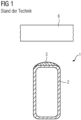
- a contact arrangement according to the prior art is shown schematically in a sectional view, with a contact arm 1 which comprises a profile body 2 and a contact element 3 .
- a mating contact piece 6 of the contact arrangement is arranged opposite the contact arm 1.
- the contact arrangement of a separating device is shown in the open state, the contact arm 1 and the mating contact piece 6 being arranged opposite one another in the manner of a cross.
- the mating contact piece 6, which z. B. is tubular with a circular-cylindrical cross-section, with the longitudinal axis in figure 1 shown parallel to the plane of the drawing.
- the contact arm 1 is in the figure 1 shown in cross section with a longitudinal axis perpendicular to the plane of the drawing.
- the profile body 2 of the contact arm 1 shown in cross section is z. B. a hollow tube or a hollow rod, with a rectangular profile, the corners are rounded in each case.
- the profile body 2 is z. B. made of steel or aluminum to ensure high mechanical stability with good electrical conductivity on the profile body 2.
- the design of the profile body 2 as a hollow body high mechanical stability is given with low weight and cost.
- the contact element 3 is non-positively and positively, electrically conductively attached to the profile body 2.
- the side is a side of the profile body 2 or of the contact arm 1, which is opposite the mating contact piece 6 of the circuit breaker.
- the contact element 3 is z. B. by welding, gluing and / or screw connections electrically conductive, mechanically stable on the profile body 2 attached.
- the contact element 3 is solid, formed as a monolithic body, and z. B. made of copper, especially with silver-plated surface.
- the profile body 2 has a diameter d, in particular in the range of centimeters, parallel to the contact surface between the profile body 2 and the contact element 3.
- the contact element 3 is strip-shaped, with a flat curve on the side which faces away from the contact surface and the counter-contact piece 6 is opposite.
- the contact element 3 Due to the rounding or the rounded surface of the contact element 3, the contact element 3 can roll on the mating contact piece in the event of a short circuit and/or when moved by wind or ice without changing the effective contact surface or losing the electrical contact. As a result, good electrical contact is maintained at all times when the disconnector is in the closed state, and electrical losses or uncontrolled opening of the contact are avoided.
- the rounded surface of the contact element 3 essentially merges into the rounded corners of the profile body 2 at the respective corners of the profile body 2 on the side of the contact surface, with an arc of a circle being formed.
- the back or side of the contact element 3 towards the profile body 2 is flat, equal to the associated side of the profile body 2.
- the two sides of the contact element 3 result in a strip-shaped contact element 3, with a longitudinal axis, which is arranged parallel to the longitudinal axis of the profile body 2, in figure 1 perpendicular to the plane of the figure.
- strip-shaped designates a flat, elongate structure or element which has a small height and a considerably smaller width than length.
- a ledge is a few millimeters to a few centimeters high, a few decimeters to a few meters long, and a few millimeters to a few centimeters wide.
- the rounded surface of the contact element 3 allows the contact arm 1 to roll on the counter-contact piece 6, but is not sufficient to strip deposits, in particular dirt, layers of ice and/or snow on the contact arm 1 or contact element 3, to push them aside and/or due to to let the curvature flake off.
- the curvature on the contact element 3 or the rounded surface of the contact element 3 is such that when the contact arm 1 moves toward the mating contact piece 6, before contact is made, e.g. B.
- Snow, ice and/or dirt can be compacted on the contact element 3 and form layers which can prevent good electrical and/or mechanical direct contact of the contact element 3 with the mating contact piece, as described above.
- large forces are required which press the contact element 3 onto the mating contact piece 6 and cause deposits to flake off or be stripped off , In particular dirt, snow and / or ice on the contact element 3 can lead.
- a drive must be dimensioned accordingly and the contact arm 1 must be mechanically stable, e.g. B. with great wall thickness, diameter d and / or stable material z. B. of the profile body 2 can be formed. This is associated with high material expenditure and high costs.
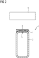
- a contact arrangement according to the invention is shown schematically in a sectional view, with a contact arm 1, which comprises a profile body 2, a first 4 and a second 3 contact element.
- a mating contact piece 6 of the contact arrangement is analogous figure 1 arranged opposite the contact arm 1.
- the contact arrangement of the separating device is also shown in the open state, with the contact arm 1 and the mating contact piece 6 being arranged opposite one another in the manner of a cross.
- the mating contact piece 6, which z. B. is tubular with a circular-cylindrical cross-section, with the longitudinal axis in figure 2 shown parallel to the plane of the drawing.
- the contact arm 1 is in the figure 2 shown in cross section with a longitudinal axis perpendicular to the plane of the drawing.
- the contact arm 1 of the contact arrangement according to the invention in figure 2 includes a profile body 2, which is equal to the profile body 2 of figure 1 is trained.
- the profile body 2 is z. B. designed as a hollow body, with a rectangular Cross section with rounded corners.
- the profile body is z. B. made of steel, aluminum and / or copper.
- a first contact piece 4 is arranged, which is designed and arranged in the shape of a strip with a longitudinal axis parallel to the longitudinal axis of the profile body 2.
- Strip-shaped also refers to a flat, elongated structure or element, which has a small height and a considerably smaller width than length.
- a ledge is a few millimeters to a few centimeters high, a few decimeters to a few meters long, and a few millimeters to a few centimeters wide.
- the first contact piece 4 has a U-shape with two legs, a first and a second leg, which are connected to one another on one side.
- the first leg of the first contact piece 4 is rigid, ie immovable relative to the profile body 2, arranged on the profile body 2 and attached to the profile body.
- An attachment is z. B. by welding, soldering, gluing and / or screw connections.
- the first leg of the first contact piece 4 in the sectional view is arranged flat with a longitudinal direction of the leg parallel to the side of the profile body 2 which is opposite the counter-contact piece 6 .
- the side of the profile body 2 which is opposite the counter-contact piece 6 forms a common surface 5 with the first leg of the first contact piece 4, i.e. a common contact surface 5.
- the first contact piece 4 is on the side of the profile body 2 which is opposite the counter-contact piece 6 lies opposite, with the first leg in a form-fitting manner on the profile body 2, and forms a mechanically stable and electrically well-conducting contact with the profile body 2 via the contact surface 5.
- the second leg of the first contact piece 4 is movable, spring-mounted, arranged directly opposite the mating contact piece 6 .
- the first contact piece 4 is z. B. formed from a spring bronze sheet, with a sheet thickness in the range of z. B. millimeters.
- the metal sheet is strip-shaped, i.e. elongated as described above, in particular with a length of the profile body 2, and is in particular designed with a width which essentially corresponds to twice the width of the side of the profile body 2 which is opposite the counter-contact piece 6.
- the sheet is folded along its longitudinal axis with a gap between the two legs of the sheet, the fold being e.g. B. takes place in the middle of the width of the sheet.
- the gap is z. B. in the range of millimeters, and the legs of the first contact piece 4 are arranged parallel to each other substantially.
- a second contact piece 3 is in the form of a strip, in particular with a length equal to the length of the first contact piece 4.
- the contact piece 3 In cross section perpendicular to the longitudinal axis of the second contact piece 3, the contact piece 3 has the shape of a circular segment, with one side of an arc of a circle and one flat side Page.
- the second contact piece 3 is arranged between the two legs of the first contact piece 4, with the flat side facing the first leg, parallel to the first leg, in particular in direct contact with the first leg, which is in contact with the profile body 2 via the contact surface 5 stands.
- the second contact piece 3 points to the second leg, with a chord of a circular arc parallel to the second leg, in particular in direct contact with the second leg at a point in the sectional view or a longitudinal axis perpendicular to the circular arc, i.e. the plane of the drawing figure 2 .
- the second contact piece 3 is z. B. a profile sheet, with a circular arc cross-section perpendicular to the longitudinal axis of the profile sheet bar, from a solid, monolithic body, which z. B. copper, aluminum and / or steel includes or consists of.
- the second contact piece 3 can be coated, e.g. B. silver plated on the surface.
- the first contact piece 4 is constructed analogously to a U-shaped clamp, between the legs of which the second contact piece 3 is clamped.
- the second contact piece 3 is z. B. on the first contact piece 4, in particular on the first leg of the first contact piece 4, by z. B. welding, soldering, gluing and / or screwed. Screw connections, which fasten the first contact piece 4 to the profile body 2, can be used to fasten the second contact piece 3 to the first contact piece 4.
- the connection of the second contact piece 3 to the first contact piece 4, in particular to the first leg of the first contact piece 4 in a form-fitting manner can result in good electrical contact between the first and second contact pieces 4, 3, and good electrical contact between the two legs of the U-shaped first contact piece 4, in particular by its clamping effect.
- the contact arm 1 When the electrical current path is closed via the isolating switch or the contact arrangement, the contact arm 1 is moved towards the mating contact piece 6 .
- the contact arm 1 comes into mechanical contact with the mating contact piece 6, the U-shaped first contact piece 4, in particular the spring-loaded, movably mounted second leg of the first contact piece 4, allows the mating contact piece 6 to roll on the first contact piece 4 or on the contact arm 1.
- the second leg of the first contact piece 4 is moved in the direction of the first leg or second contact piece 3 as it rolls off, until at most the curved shape of the second contact piece 3 is reproduced by the second leg.
- the low expenditure of force enables the contact arm 1 to be designed in a cost-effective manner, in particular with less material and a smaller diameter, and the use of a more cost-effective drive for the isolating switch.
- the exemplary embodiments described above can be combined with one another and/or can be combined with the prior art.
- So e.g. B. for the first contact element 4 other shapes are used, in particular elliptical or partially elliptical cross-sections, in particular open to one side.
- the first contact elements 4 can, for. B. be made of spring steel or bronze, and be silver or copper plated for good electrical conductivity between the mating contact piece 6 and the profile body 2.
- the profile body 2 can, for. B. be circular-cylindrical. Other forms of the profile body 2, solid or hollow tube-like z. B. triangular, elliptical, T-shaped, double-T-shaped or hexagonal cross-sectional areas of the profile body 2 perpendicular to the longitudinal axis.
- the mating contact piece 6 can be solid or hollow tube-like, with z. B. triangular, elliptical, T-shaped, double T-shaped or hexagonal cross-sectional area. Other forms for the second contact element 3 are z. B. strips with elliptical or partially elliptical cross-section.
- the second contact element 3 can also be made of an electrically non-conductive material or not a good one, e.g. B. plastic, exist in direct contact of the first contact element 4 with the profile body 2 and in the closed state of the circuit breaker with the mating contact piece 6.
Landscapes
- Arc-Extinguishing Devices That Are Switches (AREA)
- Contacts (AREA)
Applications Claiming Priority (2)
| Application Number | Priority Date | Filing Date | Title |
|---|---|---|---|
| DE102018216723.0A DE102018216723A1 (de) | 2018-09-28 | 2018-09-28 | Kontaktanordnung für einen Trennschalter und Verfahren zum elektrischen Kontaktieren der Kontaktanordnung |
| PCT/EP2019/073390 WO2020064275A1 (de) | 2018-09-28 | 2019-09-03 | Kontaktanordnung für einen trennschalter und verfahren zum elektrischen kontaktieren der kontaktanordnung |
Publications (2)
| Publication Number | Publication Date |
|---|---|
| EP3830852A1 EP3830852A1 (de) | 2021-06-09 |
| EP3830852B1 true EP3830852B1 (de) | 2023-08-30 |
Family
ID=67956729
Family Applications (1)
| Application Number | Title | Priority Date | Filing Date |
|---|---|---|---|
| EP19769072.0A Active EP3830852B1 (de) | 2018-09-28 | 2019-09-03 | Kontaktanordnung für einen trennschalter und verfahren zum elektrischen kontaktieren der kontaktanordnung |
Country Status (5)
| Country | Link |
|---|---|
| EP (1) | EP3830852B1 (pl) |
| CN (1) | CN112771636B (pl) |
| DE (1) | DE102018216723A1 (pl) |
| PL (1) | PL3830852T3 (pl) |
| WO (1) | WO2020064275A1 (pl) |
Families Citing this family (1)
| Publication number | Priority date | Publication date | Assignee | Title |
|---|---|---|---|---|
| CN112216537B (zh) * | 2020-10-21 | 2025-07-15 | 江苏东方四通科技股份有限公司 | 一种高隔离电压智能切换开关 |
Family Cites Families (5)
| Publication number | Priority date | Publication date | Assignee | Title |
|---|---|---|---|---|
| BE453262A (fr) * | 1942-08-25 | 1943-12-31 | Ressort de contact en forme de boucle, pour appareils electriques | |
| FR1117953A (fr) * | 1955-05-11 | 1956-05-29 | Dispositif à expansion, à deux contacts mobiles et à pression opposés pour sectionneurs et interrupteurs électriques, en général, et en particulier pour disjoncteurs à deux bras pour haute et basse tension et fortes intensités | |
| DE3509529A1 (de) * | 1985-03-16 | 1986-09-18 | Licentia Patent-Verwaltungs-Gmbh, 6000 Frankfurt | Nennstromkontaktanordnung fuer druckgasschalter |
| DE19830232A1 (de) * | 1998-07-07 | 2000-01-13 | Abb Research Ltd | Stromkontaktanordnungen eines Stromschalters |
| DE102016214372B4 (de) * | 2016-08-03 | 2020-01-09 | Siemens Aktiengesellschaft | Kontaktarm für Einsäulentrennschalter und dessen Verwendung |
-
2018
- 2018-09-28 DE DE102018216723.0A patent/DE102018216723A1/de not_active Withdrawn
-
2019
- 2019-09-03 CN CN201980063084.4A patent/CN112771636B/zh active Active
- 2019-09-03 PL PL19769072.0T patent/PL3830852T3/pl unknown
- 2019-09-03 WO PCT/EP2019/073390 patent/WO2020064275A1/de not_active Ceased
- 2019-09-03 EP EP19769072.0A patent/EP3830852B1/de active Active
Also Published As
| Publication number | Publication date |
|---|---|
| PL3830852T4 (pl) | 2024-03-11 |
| DE102018216723A1 (de) | 2020-04-02 |
| WO2020064275A1 (de) | 2020-04-02 |
| PL3830852T3 (pl) | 2024-03-11 |
| CN112771636B (zh) | 2024-10-15 |
| CN112771636A (zh) | 2021-05-07 |
| EP3830852A1 (de) | 2021-06-09 |
Similar Documents
| Publication | Publication Date | Title |
|---|---|---|
| DE102007033704A1 (de) | Anordnung mit einem Lasttrennschalter und einem Erdungsschalter | |
| EP3830852B1 (de) | Kontaktanordnung für einen trennschalter und verfahren zum elektrischen kontaktieren der kontaktanordnung | |
| EP3469612B1 (de) | Kontaktarm für einsäulentrennschalter und dessen verwendung | |
| EP3857583B1 (de) | Kontaktarm und verfahren zum kontaktieren für einen trennschalter | |
| EP1672659A2 (de) | Schubtrennschalter | |
| EP2107660B1 (de) | Stromschienenverbinder | |
| EP1360709A1 (de) | Schaltkontaktanordnung | |
| DE1790182C3 (de) | Begrenzt bewegliche elektrische Starkstromsteckverbindung | |
| DE102016214368B4 (de) | Kontaktanordnung für ein Hochspannungs-Schaltgerät sowie dessen Verwendung und Herstellung | |
| DE2756741A1 (de) | Elektrisches schaltgeraet mit magnetischem kontaktdruckverstaerker | |
| EP3469613B1 (de) | Kontaktarmanordnung für ein hochspannungs-schaltgerät und deren verwendung | |
| WO2005096479A1 (de) | Vorrichtung zum verbinden des mantels einer elektrischen wicklung mit einer erdungsleitung und damit ausgerüstete magnetschwebebahn | |
| EP3469610B1 (de) | Kontaktarm für ein hochspannungs-schaltgerät und verfahren zu dessen verwendung | |
| WO2015022194A1 (de) | Vorrichtung zur übertragung von kräften | |
| EP3770934A1 (de) | Schaltgerät und spannungsbegrenzungseinrichtung mit einem schaltgerät | |
| DE202009015602U1 (de) | Selbstfedernder Stromgleitkontakt | |
| DE3045206A1 (de) | Schubtrennschalter fuer mittelspannungs- und hochspannungs-schalt- und -verteileranlagen | |
| DE1640731C (de) | Ölschalter fur hohe Strome | |
| EP0101564B1 (de) | Scherentrennschalter | |
| DE8605205U1 (de) | Kontaktsystem für ein elektrisches Schaltgerät | |
| DE3116543A1 (de) | Scherentrennschalter | |
| CH645750A5 (en) | High-voltage pantograph interruptor switch | |
| DE19956992A1 (de) | Elektrische Schaltanlage | |
| DE2704541A1 (de) | Stromschienenkupplung | |
| DE1640731B2 (de) | Oelschalter fuer hohe stroeme |
Legal Events
| Date | Code | Title | Description |
|---|---|---|---|
| STAA | Information on the status of an ep patent application or granted ep patent |
Free format text: STATUS: UNKNOWN |
|
| STAA | Information on the status of an ep patent application or granted ep patent |
Free format text: STATUS: THE INTERNATIONAL PUBLICATION HAS BEEN MADE |
|
| PUAI | Public reference made under article 153(3) epc to a published international application that has entered the european phase |
Free format text: ORIGINAL CODE: 0009012 |
|
| STAA | Information on the status of an ep patent application or granted ep patent |
Free format text: STATUS: REQUEST FOR EXAMINATION WAS MADE |
|
| 17P | Request for examination filed |
Effective date: 20210302 |
|
| AK | Designated contracting states |
Kind code of ref document: A1 Designated state(s): AL AT BE BG CH CY CZ DE DK EE ES FI FR GB GR HR HU IE IS IT LI LT LU LV MC MK MT NL NO PL PT RO RS SE SI SK SM TR |
|
| DAV | Request for validation of the european patent (deleted) | ||
| DAX | Request for extension of the european patent (deleted) | ||
| GRAP | Despatch of communication of intention to grant a patent |
Free format text: ORIGINAL CODE: EPIDOSNIGR1 |
|
| STAA | Information on the status of an ep patent application or granted ep patent |
Free format text: STATUS: GRANT OF PATENT IS INTENDED |
|
| INTG | Intention to grant announced |
Effective date: 20230406 |
|
| GRAS | Grant fee paid |
Free format text: ORIGINAL CODE: EPIDOSNIGR3 |
|
| GRAA | (expected) grant |
Free format text: ORIGINAL CODE: 0009210 |
|
| STAA | Information on the status of an ep patent application or granted ep patent |
Free format text: STATUS: THE PATENT HAS BEEN GRANTED |
|
| AK | Designated contracting states |
Kind code of ref document: B1 Designated state(s): AL AT BE BG CH CY CZ DE DK EE ES FI FR GB GR HR HU IE IS IT LI LT LU LV MC MK MT NL NO PL PT RO RS SE SI SK SM TR |
|
| REG | Reference to a national code |
Ref country code: GB Ref legal event code: FG4D Free format text: NOT ENGLISH |
|
| REG | Reference to a national code |
Ref country code: CH Ref legal event code: EP |
|
| REG | Reference to a national code |
Ref country code: DE Ref legal event code: R096 Ref document number: 502019009184 Country of ref document: DE |
|
| REG | Reference to a national code |
Ref country code: IE Ref legal event code: FG4D Free format text: LANGUAGE OF EP DOCUMENT: GERMAN |
|
| REG | Reference to a national code |
Ref country code: NL Ref legal event code: FP |
|
| REG | Reference to a national code |
Ref country code: LT Ref legal event code: MG9D |
|
| PG25 | Lapsed in a contracting state [announced via postgrant information from national office to epo] |
Ref country code: GR Free format text: LAPSE BECAUSE OF FAILURE TO SUBMIT A TRANSLATION OF THE DESCRIPTION OR TO PAY THE FEE WITHIN THE PRESCRIBED TIME-LIMIT Effective date: 20231201 |
|
| PG25 | Lapsed in a contracting state [announced via postgrant information from national office to epo] |
Ref country code: IS Free format text: LAPSE BECAUSE OF FAILURE TO SUBMIT A TRANSLATION OF THE DESCRIPTION OR TO PAY THE FEE WITHIN THE PRESCRIBED TIME-LIMIT Effective date: 20231230 |
|
| PG25 | Lapsed in a contracting state [announced via postgrant information from national office to epo] |
Ref country code: SE Free format text: LAPSE BECAUSE OF FAILURE TO SUBMIT A TRANSLATION OF THE DESCRIPTION OR TO PAY THE FEE WITHIN THE PRESCRIBED TIME-LIMIT Effective date: 20230830 Ref country code: RS Free format text: LAPSE BECAUSE OF FAILURE TO SUBMIT A TRANSLATION OF THE DESCRIPTION OR TO PAY THE FEE WITHIN THE PRESCRIBED TIME-LIMIT Effective date: 20230830 Ref country code: NO Free format text: LAPSE BECAUSE OF FAILURE TO SUBMIT A TRANSLATION OF THE DESCRIPTION OR TO PAY THE FEE WITHIN THE PRESCRIBED TIME-LIMIT Effective date: 20231130 Ref country code: LV Free format text: LAPSE BECAUSE OF FAILURE TO SUBMIT A TRANSLATION OF THE DESCRIPTION OR TO PAY THE FEE WITHIN THE PRESCRIBED TIME-LIMIT Effective date: 20230830 Ref country code: LT Free format text: LAPSE BECAUSE OF FAILURE TO SUBMIT A TRANSLATION OF THE DESCRIPTION OR TO PAY THE FEE WITHIN THE PRESCRIBED TIME-LIMIT Effective date: 20230830 Ref country code: IS Free format text: LAPSE BECAUSE OF FAILURE TO SUBMIT A TRANSLATION OF THE DESCRIPTION OR TO PAY THE FEE WITHIN THE PRESCRIBED TIME-LIMIT Effective date: 20231230 Ref country code: HR Free format text: LAPSE BECAUSE OF FAILURE TO SUBMIT A TRANSLATION OF THE DESCRIPTION OR TO PAY THE FEE WITHIN THE PRESCRIBED TIME-LIMIT Effective date: 20230830 Ref country code: GR Free format text: LAPSE BECAUSE OF FAILURE TO SUBMIT A TRANSLATION OF THE DESCRIPTION OR TO PAY THE FEE WITHIN THE PRESCRIBED TIME-LIMIT Effective date: 20231201 Ref country code: FI Free format text: LAPSE BECAUSE OF FAILURE TO SUBMIT A TRANSLATION OF THE DESCRIPTION OR TO PAY THE FEE WITHIN THE PRESCRIBED TIME-LIMIT Effective date: 20230830 |
|
| PG25 | Lapsed in a contracting state [announced via postgrant information from national office to epo] |
Ref country code: ES Free format text: LAPSE BECAUSE OF FAILURE TO SUBMIT A TRANSLATION OF THE DESCRIPTION OR TO PAY THE FEE WITHIN THE PRESCRIBED TIME-LIMIT Effective date: 20230830 |
|
| PG25 | Lapsed in a contracting state [announced via postgrant information from national office to epo] |
Ref country code: SM Free format text: LAPSE BECAUSE OF FAILURE TO SUBMIT A TRANSLATION OF THE DESCRIPTION OR TO PAY THE FEE WITHIN THE PRESCRIBED TIME-LIMIT Effective date: 20230830 Ref country code: RO Free format text: LAPSE BECAUSE OF FAILURE TO SUBMIT A TRANSLATION OF THE DESCRIPTION OR TO PAY THE FEE WITHIN THE PRESCRIBED TIME-LIMIT Effective date: 20230830 Ref country code: ES Free format text: LAPSE BECAUSE OF FAILURE TO SUBMIT A TRANSLATION OF THE DESCRIPTION OR TO PAY THE FEE WITHIN THE PRESCRIBED TIME-LIMIT Effective date: 20230830 Ref country code: EE Free format text: LAPSE BECAUSE OF FAILURE TO SUBMIT A TRANSLATION OF THE DESCRIPTION OR TO PAY THE FEE WITHIN THE PRESCRIBED TIME-LIMIT Effective date: 20230830 Ref country code: DK Free format text: LAPSE BECAUSE OF FAILURE TO SUBMIT A TRANSLATION OF THE DESCRIPTION OR TO PAY THE FEE WITHIN THE PRESCRIBED TIME-LIMIT Effective date: 20230830 Ref country code: CZ Free format text: LAPSE BECAUSE OF FAILURE TO SUBMIT A TRANSLATION OF THE DESCRIPTION OR TO PAY THE FEE WITHIN THE PRESCRIBED TIME-LIMIT Effective date: 20230830 Ref country code: PT Free format text: LAPSE BECAUSE OF FAILURE TO SUBMIT A TRANSLATION OF THE DESCRIPTION OR TO PAY THE FEE WITHIN THE PRESCRIBED TIME-LIMIT Effective date: 20240102 Ref country code: SK Free format text: LAPSE BECAUSE OF FAILURE TO SUBMIT A TRANSLATION OF THE DESCRIPTION OR TO PAY THE FEE WITHIN THE PRESCRIBED TIME-LIMIT Effective date: 20230830 |
|
| REG | Reference to a national code |
Ref country code: CH Ref legal event code: PL |
|
| PG25 | Lapsed in a contracting state [announced via postgrant information from national office to epo] |
Ref country code: LU Free format text: LAPSE BECAUSE OF NON-PAYMENT OF DUE FEES Effective date: 20230903 |
|
| REG | Reference to a national code |
Ref country code: BE Ref legal event code: MM Effective date: 20230930 |
|
| PG25 | Lapsed in a contracting state [announced via postgrant information from national office to epo] |
Ref country code: LU Free format text: LAPSE BECAUSE OF NON-PAYMENT OF DUE FEES Effective date: 20230903 Ref country code: IT Free format text: LAPSE BECAUSE OF FAILURE TO SUBMIT A TRANSLATION OF THE DESCRIPTION OR TO PAY THE FEE WITHIN THE PRESCRIBED TIME-LIMIT Effective date: 20230830 Ref country code: MC Free format text: LAPSE BECAUSE OF FAILURE TO SUBMIT A TRANSLATION OF THE DESCRIPTION OR TO PAY THE FEE WITHIN THE PRESCRIBED TIME-LIMIT Effective date: 20230830 |
|
| REG | Reference to a national code |
Ref country code: DE Ref legal event code: R097 Ref document number: 502019009184 Country of ref document: DE |
|
| REG | Reference to a national code |
Ref country code: IE Ref legal event code: MM4A |
|
| PG25 | Lapsed in a contracting state [announced via postgrant information from national office to epo] |
Ref country code: IE Free format text: LAPSE BECAUSE OF NON-PAYMENT OF DUE FEES Effective date: 20230903 |
|
| PLBE | No opposition filed within time limit |
Free format text: ORIGINAL CODE: 0009261 |
|
| STAA | Information on the status of an ep patent application or granted ep patent |
Free format text: STATUS: NO OPPOSITION FILED WITHIN TIME LIMIT |
|
| PG25 | Lapsed in a contracting state [announced via postgrant information from national office to epo] |
Ref country code: CH Free format text: LAPSE BECAUSE OF NON-PAYMENT OF DUE FEES Effective date: 20230930 |
|
| GBPC | Gb: european patent ceased through non-payment of renewal fee |
Effective date: 20231130 |
|
| PG25 | Lapsed in a contracting state [announced via postgrant information from national office to epo] |
Ref country code: IE Free format text: LAPSE BECAUSE OF NON-PAYMENT OF DUE FEES Effective date: 20230903 Ref country code: FR Free format text: LAPSE BECAUSE OF NON-PAYMENT OF DUE FEES Effective date: 20231030 Ref country code: CH Free format text: LAPSE BECAUSE OF NON-PAYMENT OF DUE FEES Effective date: 20230930 Ref country code: SI Free format text: LAPSE BECAUSE OF FAILURE TO SUBMIT A TRANSLATION OF THE DESCRIPTION OR TO PAY THE FEE WITHIN THE PRESCRIBED TIME-LIMIT Effective date: 20230830 |
|
| 26N | No opposition filed |
Effective date: 20240603 |
|
| PG25 | Lapsed in a contracting state [announced via postgrant information from national office to epo] |
Ref country code: BE Free format text: LAPSE BECAUSE OF NON-PAYMENT OF DUE FEES Effective date: 20230930 |
|
| PG25 | Lapsed in a contracting state [announced via postgrant information from national office to epo] |
Ref country code: GB Free format text: LAPSE BECAUSE OF NON-PAYMENT OF DUE FEES Effective date: 20231130 |
|
| PG25 | Lapsed in a contracting state [announced via postgrant information from national office to epo] |
Ref country code: GB Free format text: LAPSE BECAUSE OF NON-PAYMENT OF DUE FEES Effective date: 20231130 |
|
| PG25 | Lapsed in a contracting state [announced via postgrant information from national office to epo] |
Ref country code: BG Free format text: LAPSE BECAUSE OF FAILURE TO SUBMIT A TRANSLATION OF THE DESCRIPTION OR TO PAY THE FEE WITHIN THE PRESCRIBED TIME-LIMIT Effective date: 20230830 |
|
| PG25 | Lapsed in a contracting state [announced via postgrant information from national office to epo] |
Ref country code: BG Free format text: LAPSE BECAUSE OF FAILURE TO SUBMIT A TRANSLATION OF THE DESCRIPTION OR TO PAY THE FEE WITHIN THE PRESCRIBED TIME-LIMIT Effective date: 20230830 |
|
| PG25 | Lapsed in a contracting state [announced via postgrant information from national office to epo] |
Ref country code: CY Free format text: LAPSE BECAUSE OF FAILURE TO SUBMIT A TRANSLATION OF THE DESCRIPTION OR TO PAY THE FEE WITHIN THE PRESCRIBED TIME-LIMIT; INVALID AB INITIO Effective date: 20190903 |
|
| PG25 | Lapsed in a contracting state [announced via postgrant information from national office to epo] |
Ref country code: HU Free format text: LAPSE BECAUSE OF FAILURE TO SUBMIT A TRANSLATION OF THE DESCRIPTION OR TO PAY THE FEE WITHIN THE PRESCRIBED TIME-LIMIT; INVALID AB INITIO Effective date: 20190903 |
|
| PGFP | Annual fee paid to national office [announced via postgrant information from national office to epo] |
Ref country code: DE Payment date: 20250926 Year of fee payment: 7 |
|
| PGFP | Annual fee paid to national office [announced via postgrant information from national office to epo] |
Ref country code: PL Payment date: 20250812 Year of fee payment: 7 Ref country code: NL Payment date: 20250925 Year of fee payment: 7 |
|
| REG | Reference to a national code |
Ref country code: AT Ref legal event code: MM01 Ref document number: 1606519 Country of ref document: AT Kind code of ref document: T Effective date: 20240903 |
|
| PG25 | Lapsed in a contracting state [announced via postgrant information from national office to epo] |
Ref country code: TR Free format text: LAPSE BECAUSE OF FAILURE TO SUBMIT A TRANSLATION OF THE DESCRIPTION OR TO PAY THE FEE WITHIN THE PRESCRIBED TIME-LIMIT Effective date: 20230830 |
|
| PG25 | Lapsed in a contracting state [announced via postgrant information from national office to epo] |
Ref country code: AT Free format text: LAPSE BECAUSE OF NON-PAYMENT OF DUE FEES Effective date: 20240903 |