EP3829791B1 - Wendehaspel und verfahren zu dessen betrieb - Google Patents
Wendehaspel und verfahren zu dessen betrieb Download PDFInfo
- Publication number
- EP3829791B1 EP3829791B1 EP19749707.6A EP19749707A EP3829791B1 EP 3829791 B1 EP3829791 B1 EP 3829791B1 EP 19749707 A EP19749707 A EP 19749707A EP 3829791 B1 EP3829791 B1 EP 3829791B1
- Authority
- EP
- European Patent Office
- Prior art keywords
- mandrel
- coiler
- winding
- free end
- coiler mandrel
- Prior art date
- Legal status (The legal status is an assumption and is not a legal conclusion. Google has not performed a legal analysis and makes no representation as to the accuracy of the status listed.)
- Not-in-force
Links
Images


Classifications
-
- B—PERFORMING OPERATIONS; TRANSPORTING
- B21—MECHANICAL METAL-WORKING WITHOUT ESSENTIALLY REMOVING MATERIAL; PUNCHING METAL
- B21C—MANUFACTURE OF METAL SHEETS, WIRE, RODS, TUBES, PROFILES OR LIKE SEMI-MANUFACTURED PRODUCTS OTHERWISE THAN BY ROLLING; AUXILIARY OPERATIONS USED IN CONNECTION WITH METAL-WORKING WITHOUT ESSENTIALLY REMOVING MATERIAL
- B21C47/00—Winding-up, coiling or winding-off metal wire, metal band or other flexible metal material characterised by features relevant to metal processing only
- B21C47/24—Transferring coils to or from winding apparatus or to or from operative position therein; Preventing uncoiling during transfer
- B21C47/245—Devices for the replacement of full reels by empty reels or vice versa, without considerable loss of time
Definitions
- the invention relates to a method for operating a turning reel according to the preamble of patent claim 1.
- the invention also relates to a corresponding turning reel as a device, according to the preamble of claim 7.
- Such turning reels are generally known in the prior art, e.g. B. from the Japanese patent application JP 64-5625 .
- the turning coiler disclosed there has a rotor on which at least one coiler mandrel is mounted with its rotor-side end eccentric to the axis of rotation of the rotor.
- the turning reel is used to wind up strip, in particular metal strip, on one of its reel mandrels.
- the rotor of the coiler mandrel is first rotated in such a way that a coiler mandrel that is still empty is positioned in a winding position. In this position, the strip is first wound onto the coiler mandrel.
- a tensile stress (tape tension) is built up in the strip for further winding.
- the coiler mandrel is rotated from said initial winding position into a finish winding position.
- the strip is finished being wound into a coil or bundle.
- the coil can then be removed from the finished winding position and transported further.
- the turning reel typically has two reel mandrels, both of which are fastened to the rotor of the turning reel eccentrically opposite to the axis of rotation of the rotor, the two reel mandrels can be pivoted alternately between the initial winding and final winding positions.
- the coiler mandrel typically already has a very high dead weight. For this reason, its free end sags or sags by typically 1 to 2 mm in relation to its end on the rotor side, even if it is not wound with a metal strip. This one-sided deformation increases under load due to belt tension and increasing waistband weight.
- This sagging or hanging down of the free end is disadvantageous in that it reduces the permissible load on the coiler mandrel and also the winding accuracy of the strip onto the coiler mandrel.
- so-called "bagging" often occurs; i.e. H. the individual windings of the coil are offset to one another like an accordion.
- a strip pull to stabilize the winding can only be applied relatively late, i. H. after a few windings of the tape, are built up slowly, which also leads to inaccuracies when winding the tape.
- the moving mandrel support bearing known from said Japanese patent application does not appear to be suitable for remedying these known disadvantages because it does not primarily support the free end of the coiler mandrel against gravity, but obviously primarily against the strip tension.
- this is evident from the fact that the two-piece bearing head of the accompanying mandrel support bearing does not grip and stabilize the coiler mandrel in a vertical direction, but primarily in a horizontal direction.
- the invention is based on the object of further developing a known method for operating a turning reel and a known turning reel in such a way that the bending or hanging down of the free end of the reel mandrel is avoided, particularly at the beginning of the winding process.
- this object is achieved by the process claimed in claim 1 .
- This is characterized in that the free end of the coiler mandrel in the winding-on position is raised against gravity to the height of its end on the rotor side with the aid of the detachably coupled, traveling mandrel support bearing.
- the free end of the coiler mandrel is already raised in the winding-on position before and/or during the winding-on of the strip. If the free end is already lifted before the beginning of the winding of the tape, the formation of a bag can already be prevented when the tape is being wound on.
- the basic rule is: the earlier you lift, the better the winding result. The less waste is produced by the winding process.
- the free end of the coiler mandrel is permanently held at the variable height of its rotor-side end with the help of the coupled mandrel support bearing during the transfer of the coiler mandrel from the initial winding position to a finish winding position - also taking into account the increasing coil weight.
- a flush winding of the strip with closely adjacent turns is ensured even during the continued winding process during the transfer of the coiler mandrel.
- Claims 1 to 4 discussed so far are aimed solely at compensating for the weight force; therefore, according to these process steps, initially only the lowering of the free end of the coiler mandrel is counteracted due to the weight; this is also expressed by the wording that the free end of the coiler mandrel is raised "to the level" of its end on the rotor side.
- the coiler mandrel and in particular its free end are also subject to at least one force component in the horizontal direction due to said strip tension to which the strip is subjected during winding.
- the free end of the coiler mandrel is basically also bent in the horizontal direction. Such a bending in the horizontal direction is also undesirable because it also leads to said errors when the strip is wound onto the coiler mandrel.
- the present invention advantageously provides that the free end of the coiler mandrel is already in the initial winding position and also during the transfer of the coiler mandrel from the initial winding position to the final winding position - also taking into account the strip tension that is increasing and changing in direction and magnitude With the help of the accompanying mandrel support bearing, it is also permanently opposite to its end on the rotor side is held.
- This expression "opposite its rotor-side end” means that the free end of the coiler mandrel is not only level with the rotor-side end, but also that the coiler mandrel is not bent in the horizontal plane. According to the invention, this is ensured in that the moving mandrel support bearing is designed not only to counteract gravity and to correct the height of the free end of the coiler mandrel, but also to counteract strip tension.
- a calculation unit is provided for the synchronization of the movement and the calculation of the specific support position and support force of the accompanying mandrel support bearing. From the variable parameters of weight, strip tension, current position of the mandrel and turning process, this continuously calculates the support position corresponding to the current position of the free end of the coiler mandrel, which is to be assumed by the traveling mandrel support bearing. A resultant force and thus a changing amount for the offset of the free end of the coiler mandrel to the fixed end of the coiler mandrel is determined from the variable load parameters of weight and strip tension.
- the coiler mandrel is additionally supported with a stationary mandrel support bearing in the finish winding position with the coil typically wound thereon. Only after the stationary mandrel support bearing has unfolded its supporting effect can the moving mandrel support bearing be uncoupled and moved back into the winding position. The coil can be finished in the finished winding position - supported by the stationary mandrel support bearing will. The finished coil can then be transported away, typically with a coil transport vehicle.
- the above-mentioned object is achieved in terms of device technology by the turning reel claimed in claim 7 .
- This is characterized in that the moving mandrel support bearing is supported on the floor, preferably a factory building, and that the adjusting device is designed to lift the bearing head together with the coupled free end of the coiler mandrel against gravity until the free end of the coiler mandrel is at the same height from the rotor-side end of the coiler mandrel when the coiler mandrel is in the winding position.
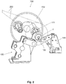
- figure 1 shows the turning coiler 100 according to the invention. It consists essentially of a rotor 110, ie here by way of example a rotating disk on which two coiler mandrels 112 are mounted here with their rotor-side end eccentric to the axis of rotation D of the rotor.
- the two coiler mandrels 112 extend generally perpendicular to the plane of the rotor. Each of the two coiler mandrels is used to wind up strip 200, in particular metal strip, into a coil.
- the reel mandrel 112 shown is in the so-called initial winding position A, while at the same time the second reel mandrel 112 is in the so-called finish winding position F.
- the functioning of the turning reel and the method according to the invention are described further below.
- an accompanying mandrel support bearing 120 is assigned to the coiler mandrel 112 in the working position A.
- This mandrel support bearing 120 has a bearing head 122 which is detachably coupled to the free end of the coiler mandrel 112 .
- the free end of the coiler mandrel is that which lies opposite the rotor-side end of the coiler mandrel with which it is mounted on the rotor 110 .
- the moving mandrel support bearing 120 is parked and supported on the floor 300 of, for example, a workshop or on a foundation.
- it has an adjusting device 124, for example in the form of a double-parallel crank mechanism for moving the bearing head 122 of the support bearing on a path predetermined by the design of the adjusting device. in particular a circular path.
- This orbit is in figure 1 marked with an arrow pointing to the right;
- the left coiler mandrel can be moved from the initial winding position A by rotating the rotor 110 about its axis of rotation D and simultaneously moving the mandrel support bearing through a suitable movement of the adjustment device 124 into the finished winding position F.
- This arrangement and positioning of the stationary mandrel support bearing 130 with respect to the traveling mandrel support bearing 120 is important to permit decoupling of the bearing head 122 from the free end of the coiler mandrel 112 in the finish winding position. Due to the fact that the stationary mandrel support bearing 130 attaches further inwards to the free end of the coiler mandrel 112, the area in front of the bearing head 122 is free so that it can be easily released for uncoupling the moving mandrel support bearing without problematic interfering edges.
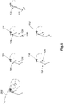
- FIG 3 shows an exemplary embodiment for the bearing head 122 of the traveling mandrel support bearing 120. It can be seen that this bearing head 122 is sleeve-shaped at its end facing the coiler mandrel 112. A sliding sleeve 128 is mounted in or on this sleeve-shaped end so that it can be displaced axially in the direction of the double arrow. To couple the bearing head 122 to the free end 113 of the coiler mandrel 112, the sliding sleeve is on the overhanging End 113a of the free end of the coiler mandrel pushed and in this position with an actuating element 129, z. B. a cylinder locked.
- the actuating element 129 also serves, if necessary, to pull back the sliding sleeve and thus to release the free end of the coiler mandrel from the bearing head 122 or from the mandrel support bearing that travels with it.
- the free end 113 of the coiler mandrel 112 is rotatably mounted within the sliding sleeve 128 or within the sleeve-shaped end of the bearing head 122.
- the design of the sleeve-shaped end ensures that the free end 113 of the coiler mandrel rests on each point of the above with reference to figure 1 mentioned trajectory can be supported against the force of gravity G by the moving mandrel support bearing.
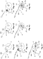
- the method initially provides that the rotor 110 of the turning coiler 100 is rotated in order to move the initially empty coiler mandrel 112 into the winding position A; please refer figure 1 .
- the bearing head 122 of the moving mandrel support bearing 120 is detachably coupled to the free end of the coiler mandrel 112 .
- This state is also in Figure 4.2 illustrated.
- FIG. 4.1 The end face of the coiler mandrel 112 in the winding position A can be seen in a schematic representation.
- the small dot-dash circle shows that rotor-side end of the coiler mandrel that is permanently mounted on the rotor 110, while the small circle drawn with a solid line shows the free end of the coiler mandrel.
- the offset shown in an exaggerated representation between the two small circles means that the free end of the coiler mandrel 112 hangs down or is lowered in relation to its 1 to 3 mm, for example, due to the high weight of the coiler mandrel 112 alone. This sagging of the free end of the coiler mandrel leads to improperly wound coils, as described in the introduction.
- this sagging of the free end 113 of the coiler mandrel 112 is counteracted in that this free end 113 is raised against gravity G to the level of the rotor-side end of the coiler mandrel 112 with the aid of the coupled mandrel support bearing that travels along.
- Figure 4.2 shows the free end 113 of the mandrel 112 in the raised position; this can be seen from the fact that in Figure 4.2 the rotor side and the free end of the coiler mandrel 112 are drawn congruently.
- the tape is started to be wound onto the coiler mandrel 112 .
- This is initially done entirely without belt tension; the strip tension is only built up when the strip, in particular the metal strip, has been wound up on the coiler mandrel 112 with a few windings (usually 1-5 windings) and can withstand an acting tensile stress or an acting strip tension.
- the free end 113 of the coiler mandrel 112 in the winding-on position A is preferably already raised to the level of the end on the rotor side before and/or during the winding-on of the strip. If possible, the free end of the coiler mandrel should already be raised to the level of the end on the rotor side before the beginning of the winding, because then the problems described in the introduction when winding the strip can be avoided right from the start of the winding.
- Figure 4.3 shows the structure of the tape still in the winding position A; the structure of the strip tension is indicated there parallel to the strip 200 by the two arrows pointing towards one another.
- the double parallel crank mechanism 124 of the traveling mandrel support bearing holds its bearing head and thus also the free end 113 of the coiler mandrel 112 in the winding position at the level of the end on the rotor side.
- Figure 4.4 shows the reel mandrel 112 with the strip 200 partially wound under strip tension during its transfer from the initial winding position A to the finish winding position.
- the adjusting device 124 here by way of example in the form of the double-crank mechanism, always keeps the free end 113 of the coiler mandrel 112 level with the end of the coiler mandrel on the rotor side.
- the adjustment device 124 also counteracts the strip tension at the free end of the coiler mandrel, so that no lateral offset occurs between the two ends of the coiler mandrel 112 either.
- Figure 4.5 shows the coiler mandrel 112 with the coil diameter, which has meanwhile increased, in the finish winding position F.
- the adjusting device 124 is suitably rotated accordingly.
- Figure 4.6 shows the coiler mandrel 112 in the finish winding position F, where the free end 113 of the coiler mandrel 112 is now also supported by the static or stationary mandrel support bearing 130 .
- the stationary mandrel support bearing 130 alone supports the free end of the coiler mandrel, so that the moving mandrel support bearing is uncoupled from the free end, for example by pulling back the sliding sleeve 128 can be.
- the uncoupled moving mandrel support bearing can then be moved back into the winding position, as in Figure 4.7 shown.
- the coil can be fully wound and later removed from the coiler mandrel without interfering with the accompanying mandrel support bearing.
- figure 5 shows again the already from the Figures 4.1 - 4.7 known different stations of the coiler mandrel during its transfer from the initial winding position A to the final winding position F. Particularly clear are in figure 5 which also already in the Figures 4.1 - 4.7 indicated acting forces to recognize.
- the total force acting on the coiler mandrel 112 or the resulting force F RES results in each case as a vectorial sum of the weight force F G and the tensile force Fz due to the strip tension. It can be seen that the weight force F G , which always acts in the vertical direction, is still relatively small in the initial winding position A and increases towards the finished winding position.
- the total forces and the current turning position are calculated by a calculation unit (not shown), which specifies the support position to be assumed by the moving mandrel support bearing and has it carried out by the adjusting device.
- figure 6 shows again the already with reference to the Figures 4.1 - 4.7 partially described positions of the coiler mandrel during its transfer from the initial winding position to the final winding position.
- figure 6 shows in particular different possibilities for placing drives 126 in the pivot points of the double-crank mechanism 124.
- the drives are each symbolized by a sector-like division of the pivot points. In principle, it is sufficient to provide only one drive in one pivot point, as shown in the second column in figure 1 is shown as an example and alternative for two pivot points. Better, but also more expensive, is the installation of two drives 126 in different pivot points of the double-crank mechanism 124, as shown in the third column in figure 6 is shown.
- the flexibility of the winding process is advantageously significantly increased by the method and the device according to the invention.
- the number of possible windings in the winding position and the permissible strip tension values in the winding position can be increased; the turning speed can be changed. This means that the winding process can be carried out much more flexibly in terms of process technology.
Landscapes
- Engineering & Computer Science (AREA)
- Mechanical Engineering (AREA)
- Winding Of Webs (AREA)
- Winding, Rewinding, Material Storage Devices (AREA)
Applications Claiming Priority (2)
| Application Number | Priority Date | Filing Date | Title |
|---|---|---|---|
| DE102018212958.4A DE102018212958A1 (de) | 2018-08-02 | 2018-08-02 | Wendehaspel und Verfahren zu dessen Betrieb |
| PCT/EP2019/070829 WO2020025773A1 (de) | 2018-08-02 | 2019-08-01 | Wendehaspel und verfahren zu dessen betrieb |
Publications (2)
| Publication Number | Publication Date |
|---|---|
| EP3829791A1 EP3829791A1 (de) | 2021-06-09 |
| EP3829791B1 true EP3829791B1 (de) | 2022-03-30 |
Family
ID=67544244
Family Applications (1)
| Application Number | Title | Priority Date | Filing Date |
|---|---|---|---|
| EP19749707.6A Not-in-force EP3829791B1 (de) | 2018-08-02 | 2019-08-01 | Wendehaspel und verfahren zu dessen betrieb |
Country Status (5)
| Country | Link |
|---|---|
| EP (1) | EP3829791B1 (https=) |
| JP (1) | JP7168761B2 (https=) |
| CN (1) | CN112512713B (https=) |
| DE (1) | DE102018212958A1 (https=) |
| WO (1) | WO2020025773A1 (https=) |
Families Citing this family (2)
| Publication number | Priority date | Publication date | Assignee | Title |
|---|---|---|---|---|
| CN119833696A (zh) * | 2023-10-12 | 2025-04-15 | 宁德时代新能源科技股份有限公司 | 电极组件制造装置及方法、电池制造设备及方法 |
| CN120246740B (zh) * | 2025-06-06 | 2025-08-08 | 福州祥和医疗防护用品科技有限公司 | 一种全自动口罩机用布料放置架 |
Citations (1)
| Publication number | Priority date | Publication date | Assignee | Title |
|---|---|---|---|---|
| JPH0822448B2 (ja) * | 1987-06-26 | 1996-03-06 | 石川島播磨重工業株式会社 | カロ−ゼルリ−ル装置 |
Family Cites Families (5)
| Publication number | Priority date | Publication date | Assignee | Title |
|---|---|---|---|---|
| JPH0643219B2 (ja) * | 1985-04-05 | 1994-06-08 | 株式会社日立製作所 | 巻取り、巻出し装置のドラム支持装置 |
| JPH0771694B2 (ja) * | 1989-12-22 | 1995-08-02 | 株式会社日立製作所 | 帯鋼の巻取り・巻出し機 |
| CN101642783B (zh) * | 2008-08-07 | 2011-08-31 | 中冶赛迪工程技术股份有限公司 | 一种双卷筒卷取机 |
| DE102014216221A1 (de) * | 2014-05-26 | 2015-11-26 | Sms Group Gmbh | Vorrichtung und Verfahren zum Wickeln eines Bandmaterials |
| DE102017205355A1 (de) * | 2016-09-02 | 2018-03-08 | Sms Group Gmbh | Abstützvorrichtung für einen Wendelhaspel sowie Haspelanlage |
-
2018
- 2018-08-02 DE DE102018212958.4A patent/DE102018212958A1/de not_active Withdrawn
-
2019
- 2019-08-01 JP JP2021505660A patent/JP7168761B2/ja active Active
- 2019-08-01 EP EP19749707.6A patent/EP3829791B1/de not_active Not-in-force
- 2019-08-01 WO PCT/EP2019/070829 patent/WO2020025773A1/de not_active Ceased
- 2019-08-01 CN CN201980051392.5A patent/CN112512713B/zh active Active
Patent Citations (1)
| Publication number | Priority date | Publication date | Assignee | Title |
|---|---|---|---|---|
| JPH0822448B2 (ja) * | 1987-06-26 | 1996-03-06 | 石川島播磨重工業株式会社 | カロ−ゼルリ−ル装置 |
Also Published As
| Publication number | Publication date |
|---|---|
| JP2021531980A (ja) | 2021-11-25 |
| EP3829791A1 (de) | 2021-06-09 |
| CN112512713B (zh) | 2023-06-13 |
| CN112512713A (zh) | 2021-03-16 |
| JP7168761B2 (ja) | 2022-11-09 |
| DE102018212958A1 (de) | 2020-02-06 |
| WO2020025773A1 (de) | 2020-02-06 |
Similar Documents
| Publication | Publication Date | Title |
|---|---|---|
| DE69902208T2 (de) | Wickelmaschine zum Formen von Rollen grossen Durchmessers bahnenförmigen Materials | |
| EP2648860B1 (de) | Vorrichtung und verfahren zum handhaben eines metallbandes | |
| AT505818B1 (de) | Verfahren und anordnung bei einer abrollvorrichtung für eine faserbahn | |
| DE60101373T2 (de) | Vorrichtung zum auf- und abwickeln von dünnen bändern mit automatischer zentrierung | |
| DE102007053588A1 (de) | Abrollvorrichtung für Wickelrollen | |
| DE2519988B2 (de) | Wickelverfahren fuer vorgewalzte heisse metallbaender und wickelvorrichtung zur durchfuehrung dieses verfahrens | |
| EP3829791B1 (de) | Wendehaspel und verfahren zu dessen betrieb | |
| EP3148720B1 (de) | Vorrichtung und verfahren zum wickeln eines bandmaterials | |
| DE102018112690B4 (de) | Vorrichtung zum Entfalten eines aufgerollten länglichen Hohlkörpers | |
| DD208337A5 (de) | Verfahren und vorrichtung zum kontinuierlichen spulenwechsel an ein- oder mehrgaengigen, kontinuierlich arbeitenden wickelstationen fuer strangfoermiges gut | |
| EP2313335A1 (de) | Vorrichtung und verfahren zum auf- und/oder abwickeln von materialbahnen | |
| WO2025157823A1 (de) | Vorrichtung zum anpressen und trennen einer materialbahn für einen wendewickler | |
| DE2431515A1 (de) | Vorrichtung zum aufwickeln von draht auf eine spule | |
| DE2420567A1 (de) | Wickelmaschine fuer bandmaterial | |
| DE60118964T2 (de) | Vorrichtung und verfahren zum wickeln von bahnen | |
| EP3507032B1 (de) | Abstützvorrichtung für einen wendehaspel sowie haspelanlage | |
| EP1778420B1 (de) | Walzanlage und verfahren zum erzeugen eines metallbandes | |
| EP3052255B1 (de) | Vorrichtung zum wickeln eines bandmaterials zu einem coil | |
| DE3028607C2 (https=) | ||
| DE2821371A1 (de) | Bandspeicher | |
| DE60109323T2 (de) | Vorrichtung und verfahren zum wickeln von bahnen | |
| DE69921698T2 (de) | Speicherspule mit aufgewickeltem zwischenband | |
| EP0909596A2 (de) | Abhaspelvorrichung zum Abhaspeln eines Bandes | |
| EP2829333A1 (de) | Bandhaspelanordnung zum Auf- und/oder Abwickeln eines Metallbandes | |
| DE1911551A1 (de) | Vorrichtung zum Wickeln konzentrischer Spulen bzw. Spulengruppen fuer elektrische Maschinen |
Legal Events
| Date | Code | Title | Description |
|---|---|---|---|
| STAA | Information on the status of an ep patent application or granted ep patent |
Free format text: STATUS: UNKNOWN |
|
| STAA | Information on the status of an ep patent application or granted ep patent |
Free format text: STATUS: THE INTERNATIONAL PUBLICATION HAS BEEN MADE |
|
| PUAI | Public reference made under article 153(3) epc to a published international application that has entered the european phase |
Free format text: ORIGINAL CODE: 0009012 |
|
| STAA | Information on the status of an ep patent application or granted ep patent |
Free format text: STATUS: REQUEST FOR EXAMINATION WAS MADE |
|
| 17P | Request for examination filed |
Effective date: 20210302 |
|
| AK | Designated contracting states |
Kind code of ref document: A1 Designated state(s): AL AT BE BG CH CY CZ DE DK EE ES FI FR GB GR HR HU IE IS IT LI LT LU LV MC MK MT NL NO PL PT RO RS SE SI SK SM TR |
|
| DAV | Request for validation of the european patent (deleted) | ||
| DAX | Request for extension of the european patent (deleted) | ||
| GRAP | Despatch of communication of intention to grant a patent |
Free format text: ORIGINAL CODE: EPIDOSNIGR1 |
|
| STAA | Information on the status of an ep patent application or granted ep patent |
Free format text: STATUS: GRANT OF PATENT IS INTENDED |
|
| INTG | Intention to grant announced |
Effective date: 20211117 |
|
| GRAS | Grant fee paid |
Free format text: ORIGINAL CODE: EPIDOSNIGR3 |
|
| GRAA | (expected) grant |
Free format text: ORIGINAL CODE: 0009210 |
|
| STAA | Information on the status of an ep patent application or granted ep patent |
Free format text: STATUS: THE PATENT HAS BEEN GRANTED |
|
| AK | Designated contracting states |
Kind code of ref document: B1 Designated state(s): AL AT BE BG CH CY CZ DE DK EE ES FI FR GB GR HR HU IE IS IT LI LT LU LV MC MK MT NL NO PL PT RO RS SE SI SK SM TR |
|
| REG | Reference to a national code |
Ref country code: GB Ref legal event code: FG4D Free format text: NOT ENGLISH |
|
| REG | Reference to a national code |
Ref country code: CH Ref legal event code: EP |
|
| REG | Reference to a national code |
Ref country code: DE Ref legal event code: R096 Ref document number: 502019003905 Country of ref document: DE |
|
| REG | Reference to a national code |
Ref country code: AT Ref legal event code: REF Ref document number: 1478698 Country of ref document: AT Kind code of ref document: T Effective date: 20220415 |
|
| REG | Reference to a national code |
Ref country code: IE Ref legal event code: FG4D Free format text: LANGUAGE OF EP DOCUMENT: GERMAN |
|
| REG | Reference to a national code |
Ref country code: LT Ref legal event code: MG9D |
|
| PG25 | Lapsed in a contracting state [announced via postgrant information from national office to epo] |
Ref country code: SE Free format text: LAPSE BECAUSE OF FAILURE TO SUBMIT A TRANSLATION OF THE DESCRIPTION OR TO PAY THE FEE WITHIN THE PRESCRIBED TIME-LIMIT Effective date: 20220330 Ref country code: RS Free format text: LAPSE BECAUSE OF FAILURE TO SUBMIT A TRANSLATION OF THE DESCRIPTION OR TO PAY THE FEE WITHIN THE PRESCRIBED TIME-LIMIT Effective date: 20220330 Ref country code: NO Free format text: LAPSE BECAUSE OF FAILURE TO SUBMIT A TRANSLATION OF THE DESCRIPTION OR TO PAY THE FEE WITHIN THE PRESCRIBED TIME-LIMIT Effective date: 20220630 Ref country code: LT Free format text: LAPSE BECAUSE OF FAILURE TO SUBMIT A TRANSLATION OF THE DESCRIPTION OR TO PAY THE FEE WITHIN THE PRESCRIBED TIME-LIMIT Effective date: 20220330 Ref country code: HR Free format text: LAPSE BECAUSE OF FAILURE TO SUBMIT A TRANSLATION OF THE DESCRIPTION OR TO PAY THE FEE WITHIN THE PRESCRIBED TIME-LIMIT Effective date: 20220330 Ref country code: BG Free format text: LAPSE BECAUSE OF FAILURE TO SUBMIT A TRANSLATION OF THE DESCRIPTION OR TO PAY THE FEE WITHIN THE PRESCRIBED TIME-LIMIT Effective date: 20220630 |
|
| REG | Reference to a national code |
Ref country code: NL Ref legal event code: MP Effective date: 20220330 |
|
| PG25 | Lapsed in a contracting state [announced via postgrant information from national office to epo] |
Ref country code: LV Free format text: LAPSE BECAUSE OF FAILURE TO SUBMIT A TRANSLATION OF THE DESCRIPTION OR TO PAY THE FEE WITHIN THE PRESCRIBED TIME-LIMIT Effective date: 20220330 Ref country code: GR Free format text: LAPSE BECAUSE OF FAILURE TO SUBMIT A TRANSLATION OF THE DESCRIPTION OR TO PAY THE FEE WITHIN THE PRESCRIBED TIME-LIMIT Effective date: 20220701 Ref country code: FI Free format text: LAPSE BECAUSE OF FAILURE TO SUBMIT A TRANSLATION OF THE DESCRIPTION OR TO PAY THE FEE WITHIN THE PRESCRIBED TIME-LIMIT Effective date: 20220330 |
|
| PG25 | Lapsed in a contracting state [announced via postgrant information from national office to epo] |
Ref country code: NL Free format text: LAPSE BECAUSE OF FAILURE TO SUBMIT A TRANSLATION OF THE DESCRIPTION OR TO PAY THE FEE WITHIN THE PRESCRIBED TIME-LIMIT Effective date: 20220330 |
|
| PG25 | Lapsed in a contracting state [announced via postgrant information from national office to epo] |
Ref country code: SM Free format text: LAPSE BECAUSE OF FAILURE TO SUBMIT A TRANSLATION OF THE DESCRIPTION OR TO PAY THE FEE WITHIN THE PRESCRIBED TIME-LIMIT Effective date: 20220330 Ref country code: SK Free format text: LAPSE BECAUSE OF FAILURE TO SUBMIT A TRANSLATION OF THE DESCRIPTION OR TO PAY THE FEE WITHIN THE PRESCRIBED TIME-LIMIT Effective date: 20220330 Ref country code: RO Free format text: LAPSE BECAUSE OF FAILURE TO SUBMIT A TRANSLATION OF THE DESCRIPTION OR TO PAY THE FEE WITHIN THE PRESCRIBED TIME-LIMIT Effective date: 20220330 Ref country code: PT Free format text: LAPSE BECAUSE OF FAILURE TO SUBMIT A TRANSLATION OF THE DESCRIPTION OR TO PAY THE FEE WITHIN THE PRESCRIBED TIME-LIMIT Effective date: 20220801 Ref country code: ES Free format text: LAPSE BECAUSE OF FAILURE TO SUBMIT A TRANSLATION OF THE DESCRIPTION OR TO PAY THE FEE WITHIN THE PRESCRIBED TIME-LIMIT Effective date: 20220330 Ref country code: EE Free format text: LAPSE BECAUSE OF FAILURE TO SUBMIT A TRANSLATION OF THE DESCRIPTION OR TO PAY THE FEE WITHIN THE PRESCRIBED TIME-LIMIT Effective date: 20220330 Ref country code: CZ Free format text: LAPSE BECAUSE OF FAILURE TO SUBMIT A TRANSLATION OF THE DESCRIPTION OR TO PAY THE FEE WITHIN THE PRESCRIBED TIME-LIMIT Effective date: 20220330 |
|
| PG25 | Lapsed in a contracting state [announced via postgrant information from national office to epo] |
Ref country code: PL Free format text: LAPSE BECAUSE OF FAILURE TO SUBMIT A TRANSLATION OF THE DESCRIPTION OR TO PAY THE FEE WITHIN THE PRESCRIBED TIME-LIMIT Effective date: 20220330 Ref country code: IS Free format text: LAPSE BECAUSE OF FAILURE TO SUBMIT A TRANSLATION OF THE DESCRIPTION OR TO PAY THE FEE WITHIN THE PRESCRIBED TIME-LIMIT Effective date: 20220730 Ref country code: AL Free format text: LAPSE BECAUSE OF FAILURE TO SUBMIT A TRANSLATION OF THE DESCRIPTION OR TO PAY THE FEE WITHIN THE PRESCRIBED TIME-LIMIT Effective date: 20220330 |
|
| REG | Reference to a national code |
Ref country code: DE Ref legal event code: R097 Ref document number: 502019003905 Country of ref document: DE |
|
| PG25 | Lapsed in a contracting state [announced via postgrant information from national office to epo] |
Ref country code: DK Free format text: LAPSE BECAUSE OF FAILURE TO SUBMIT A TRANSLATION OF THE DESCRIPTION OR TO PAY THE FEE WITHIN THE PRESCRIBED TIME-LIMIT Effective date: 20220330 |
|
| PLBE | No opposition filed within time limit |
Free format text: ORIGINAL CODE: 0009261 |
|
| STAA | Information on the status of an ep patent application or granted ep patent |
Free format text: STATUS: NO OPPOSITION FILED WITHIN TIME LIMIT |
|
| 26N | No opposition filed |
Effective date: 20230103 |
|
| PG25 | Lapsed in a contracting state [announced via postgrant information from national office to epo] |
Ref country code: MC Free format text: LAPSE BECAUSE OF FAILURE TO SUBMIT A TRANSLATION OF THE DESCRIPTION OR TO PAY THE FEE WITHIN THE PRESCRIBED TIME-LIMIT Effective date: 20220330 |
|
| REG | Reference to a national code |
Ref country code: CH Ref legal event code: PL |
|
| PG25 | Lapsed in a contracting state [announced via postgrant information from national office to epo] |
Ref country code: LU Free format text: LAPSE BECAUSE OF NON-PAYMENT OF DUE FEES Effective date: 20220801 Ref country code: LI Free format text: LAPSE BECAUSE OF NON-PAYMENT OF DUE FEES Effective date: 20220831 Ref country code: CH Free format text: LAPSE BECAUSE OF NON-PAYMENT OF DUE FEES Effective date: 20220831 |
|
| PG25 | Lapsed in a contracting state [announced via postgrant information from national office to epo] |
Ref country code: SI Free format text: LAPSE BECAUSE OF FAILURE TO SUBMIT A TRANSLATION OF THE DESCRIPTION OR TO PAY THE FEE WITHIN THE PRESCRIBED TIME-LIMIT Effective date: 20220330 |
|
| PG25 | Lapsed in a contracting state [announced via postgrant information from national office to epo] |
Ref country code: IE Free format text: LAPSE BECAUSE OF NON-PAYMENT OF DUE FEES Effective date: 20220801 |
|
| P01 | Opt-out of the competence of the unified patent court (upc) registered |
Effective date: 20230707 |
|
| PGFP | Annual fee paid to national office [announced via postgrant information from national office to epo] |
Ref country code: IT Payment date: 20230825 Year of fee payment: 5 Ref country code: GB Payment date: 20230822 Year of fee payment: 5 |
|
| PGFP | Annual fee paid to national office [announced via postgrant information from national office to epo] |
Ref country code: FR Payment date: 20230828 Year of fee payment: 5 Ref country code: BE Payment date: 20230821 Year of fee payment: 5 |
|
| PG25 | Lapsed in a contracting state [announced via postgrant information from national office to epo] |
Ref country code: MK Free format text: LAPSE BECAUSE OF FAILURE TO SUBMIT A TRANSLATION OF THE DESCRIPTION OR TO PAY THE FEE WITHIN THE PRESCRIBED TIME-LIMIT Effective date: 20220330 Ref country code: CY Free format text: LAPSE BECAUSE OF FAILURE TO SUBMIT A TRANSLATION OF THE DESCRIPTION OR TO PAY THE FEE WITHIN THE PRESCRIBED TIME-LIMIT Effective date: 20220330 |
|
| PG25 | Lapsed in a contracting state [announced via postgrant information from national office to epo] |
Ref country code: HU Free format text: LAPSE BECAUSE OF FAILURE TO SUBMIT A TRANSLATION OF THE DESCRIPTION OR TO PAY THE FEE WITHIN THE PRESCRIBED TIME-LIMIT; INVALID AB INITIO Effective date: 20190801 |
|
| PG25 | Lapsed in a contracting state [announced via postgrant information from national office to epo] |
Ref country code: TR Free format text: LAPSE BECAUSE OF FAILURE TO SUBMIT A TRANSLATION OF THE DESCRIPTION OR TO PAY THE FEE WITHIN THE PRESCRIBED TIME-LIMIT Effective date: 20220330 |
|
| PG25 | Lapsed in a contracting state [announced via postgrant information from national office to epo] |
Ref country code: MT Free format text: LAPSE BECAUSE OF FAILURE TO SUBMIT A TRANSLATION OF THE DESCRIPTION OR TO PAY THE FEE WITHIN THE PRESCRIBED TIME-LIMIT Effective date: 20220330 |
|
| PGFP | Annual fee paid to national office [announced via postgrant information from national office to epo] |
Ref country code: DE Payment date: 20240821 Year of fee payment: 6 |
|
| GBPC | Gb: european patent ceased through non-payment of renewal fee |
Effective date: 20240801 |
|
| REG | Reference to a national code |
Ref country code: BE Ref legal event code: MM Effective date: 20240831 |
|
| PG25 | Lapsed in a contracting state [announced via postgrant information from national office to epo] |
Ref country code: GB Free format text: LAPSE BECAUSE OF NON-PAYMENT OF DUE FEES Effective date: 20240801 |
|
| PG25 | Lapsed in a contracting state [announced via postgrant information from national office to epo] |
Ref country code: IT Free format text: LAPSE BECAUSE OF NON-PAYMENT OF DUE FEES Effective date: 20240801 Ref country code: BE Free format text: LAPSE BECAUSE OF NON-PAYMENT OF DUE FEES Effective date: 20240831 |
|
| PG25 | Lapsed in a contracting state [announced via postgrant information from national office to epo] |
Ref country code: FR Free format text: LAPSE BECAUSE OF NON-PAYMENT OF DUE FEES Effective date: 20240831 |
|
| REG | Reference to a national code |
Ref country code: AT Ref legal event code: MM01 Ref document number: 1478698 Country of ref document: AT Kind code of ref document: T Effective date: 20240801 |
|
| PG25 | Lapsed in a contracting state [announced via postgrant information from national office to epo] |
Ref country code: AT Free format text: LAPSE BECAUSE OF NON-PAYMENT OF DUE FEES Effective date: 20240801 |
|
| REG | Reference to a national code |
Ref country code: DE Ref legal event code: R119 Ref document number: 502019003905 Country of ref document: DE |
|
| PGFP | Annual fee paid to national office [announced via postgrant information from national office to epo] |
Ref country code: AT Payment date: 20260410 Year of fee payment: 5 |