EP3828672B1 - Eingabevorrichtung für computer - Google Patents
Eingabevorrichtung für computer Download PDFInfo
- Publication number
- EP3828672B1 EP3828672B1 EP20209915.6A EP20209915A EP3828672B1 EP 3828672 B1 EP3828672 B1 EP 3828672B1 EP 20209915 A EP20209915 A EP 20209915A EP 3828672 B1 EP3828672 B1 EP 3828672B1
- Authority
- EP
- European Patent Office
- Prior art keywords
- plunger
- ball
- housing
- support
- bottom side
- Prior art date
- Legal status (The legal status is an assumption and is not a legal conclusion. Google has not performed a legal analysis and makes no representation as to the accuracy of the status listed.)
- Active
Links
Images




Classifications
-
- G—PHYSICS
- G06—COMPUTING OR CALCULATING; COUNTING
- G06F—ELECTRIC DIGITAL DATA PROCESSING
- G06F3/00—Input arrangements for transferring data to be processed into a form capable of being handled by the computer; Output arrangements for transferring data from processing unit to output unit, e.g. interface arrangements
- G06F3/01—Input arrangements or combined input and output arrangements for interaction between user and computer
- G06F3/03—Arrangements for converting the position or the displacement of a member into a coded form
- G06F3/033—Pointing devices displaced or positioned by the user, e.g. mice, trackballs, pens or joysticks; Accessories therefor
- G06F3/0354—Pointing devices displaced or positioned by the user, e.g. mice, trackballs, pens or joysticks; Accessories therefor with detection of two-dimensional [2D] relative movements between the device, or an operating part thereof, and a plane or surface, e.g. 2D mice, trackballs, pens or pucks
- G06F3/03549—Trackballs
-
- G—PHYSICS
- G06—COMPUTING OR CALCULATING; COUNTING
- G06F—ELECTRIC DIGITAL DATA PROCESSING
- G06F3/00—Input arrangements for transferring data to be processed into a form capable of being handled by the computer; Output arrangements for transferring data from processing unit to output unit, e.g. interface arrangements
- G06F3/01—Input arrangements or combined input and output arrangements for interaction between user and computer
- G06F3/03—Arrangements for converting the position or the displacement of a member into a coded form
- G06F3/033—Pointing devices displaced or positioned by the user, e.g. mice, trackballs, pens or joysticks; Accessories therefor
- G06F3/0354—Pointing devices displaced or positioned by the user, e.g. mice, trackballs, pens or joysticks; Accessories therefor with detection of two-dimensional [2D] relative movements between the device, or an operating part thereof, and a plane or surface, e.g. 2D mice, trackballs, pens or pucks
- G06F3/03543—Mice or pucks
-
- G—PHYSICS
- G06—COMPUTING OR CALCULATING; COUNTING
- G06F—ELECTRIC DIGITAL DATA PROCESSING
- G06F3/00—Input arrangements for transferring data to be processed into a form capable of being handled by the computer; Output arrangements for transferring data from processing unit to output unit, e.g. interface arrangements
- G06F3/01—Input arrangements or combined input and output arrangements for interaction between user and computer
- G06F3/03—Arrangements for converting the position or the displacement of a member into a coded form
- G06F3/033—Pointing devices displaced or positioned by the user, e.g. mice, trackballs, pens or joysticks; Accessories therefor
- G06F3/0354—Pointing devices displaced or positioned by the user, e.g. mice, trackballs, pens or joysticks; Accessories therefor with detection of two-dimensional [2D] relative movements between the device, or an operating part thereof, and a plane or surface, e.g. 2D mice, trackballs, pens or pucks
-
- G—PHYSICS
- G06—COMPUTING OR CALCULATING; COUNTING
- G06F—ELECTRIC DIGITAL DATA PROCESSING
- G06F3/00—Input arrangements for transferring data to be processed into a form capable of being handled by the computer; Output arrangements for transferring data from processing unit to output unit, e.g. interface arrangements
- G06F3/01—Input arrangements or combined input and output arrangements for interaction between user and computer
- G06F3/03—Arrangements for converting the position or the displacement of a member into a coded form
- G06F3/033—Pointing devices displaced or positioned by the user, e.g. mice, trackballs, pens or joysticks; Accessories therefor
- G06F3/0362—Pointing devices displaced or positioned by the user, e.g. mice, trackballs, pens or joysticks; Accessories therefor with detection of one-dimensional [1D] translations or rotations of an operating part of the device, e.g. scroll wheels, sliders, knobs, rollers or belts
-
- G—PHYSICS
- G06—COMPUTING OR CALCULATING; COUNTING
- G06F—ELECTRIC DIGITAL DATA PROCESSING
- G06F3/00—Input arrangements for transferring data to be processed into a form capable of being handled by the computer; Output arrangements for transferring data from processing unit to output unit, e.g. interface arrangements
- G06F3/01—Input arrangements or combined input and output arrangements for interaction between user and computer
- G06F3/03—Arrangements for converting the position or the displacement of a member into a coded form
- G06F3/033—Pointing devices displaced or positioned by the user, e.g. mice, trackballs, pens or joysticks; Accessories therefor
- G06F3/039—Accessories therefor, e.g. mouse pads
Definitions
- the present disclosure relates to a computer input device.
- the present disclosure relates to a trackball for use with a computer system.
- US 2011/105231 A1 discloses a game controller.
- One or more main control input interfaces on the game controller consist of generalized sockets.
- a variety of modular input interfaces can be plugged into these sockets.
- Hardware specific to the input type of the modular input is contained within the modular input itself, and plugged in via an interface. This allows for dual analog sticks, a combination of analog and trackball, or further any combination of touchpad, directional pad, or additional components.
- JP 2004265017 A discloses a track ball device enabling an operator to take out a ball when removing dust adhered to the ball or changing the ball to the one of a color desired by an operator.
- the device comprises a substantially hollow hemispherical ball support member for rotatably supporting the ball from beneath and a ball separating mechanism for raising the ball above the ball support member.
- the ball separating mechanism has a push-up member for pushing the ball up and a rotatable driving arm for moving the push-up member closer to and separating the push-up member from the ball, so that the operator can take out the ball.
- JP 2010165033 A discloses a ball take-out structure for a trackball for taking out a ball used in the trackball, without using a special structure provided in a separate jig or ring.
- the ball take-out structure is provided in the trackball, and includes an in-casing fixing portion fixed in an inside of casing, a push-up action portion applied with a push-up action of pushing up the ball directly or indirectly from an under side, and a holding portion projected to an outside of the trackball casing to be held.
- US2018/0103929 discloses a medical input device for receiving an input of a command signal.
- the medical input device includes: a main body unit that is a housing; a track ball housed in the main body unit and provided rotatably; an opening forming member configured to form at least an opening having a diameter smaller than that of the track ball, the track ball partially protruding through the opening; and a moving member having an inclined surface on which the track ball is configured to ride, the moving member being movable in a direction of approaching the track ball or in a direction of receding from the track ball.
- a trackball input device according to claim 1 is provided.
- a method according to claim 7 is provided. Preferred embodiments of the invention are provided in the dependent claims.
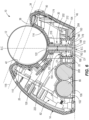
- FIGS. 1-5 illustrate a computer input device 10, which is illustrated as a trackball, that is configured to be used with a computer system and has a ball 12 that is movable (e.g., rotatable) to communicate with a monitor of the computer system.
- the trackball 10 includes a housing 14 that supports a ball 12.
- the housing 14 includes a longitudinal axis A, a first side 18 (e.g., top side), a second side 22 (e.g., bottom side) spaced apart from the first side 18, a third side 26 (e.g., right side), and a fourth side 30 (e.g., left side) spaced apart from the third side 26.
- the top and bottom sides 18, 22 are positioned between the right and left sides 26, 30.
- the top side 18 defines a plane 34 and includes a depression 38, and an aperture 42 ( FIGS. 6 and 7 ) positioned within the depression 38 and extending through top side 18.
- the bottom side 22 is configured to support the trackball 10 on a support surface (e.g., a desk or the like), and has a surface that defines a plane 46 that is parallel to the support surface.
- the plane 34 of the top side 18 is positioned at a non-parallel angle relative to the support surface (e.g., at an oblique angle).
- the plane 34 may be parallel to the support surface.
- the plane 34 may be perpendicular or nearly perpendicular to the support surface.
- the bottom side 22 includes a power switch 50, a WIFI button 54, and a dots per inch (DPI) button 58.
- the left side 30 and the right side 26 both extend from both the top side 18 and the bottom side 22 at oblique angles.
- the right side 26 includes a first button 62 (e.g., a right-click button) and a second button 66 (e.g., a left-click button) on opposite sides of a rotatable wheel 70.
- the housing 14 also includes additional buttons 74, 78 positioned in between the right side 26 and the top side 18 and between the left side 30 and the top side 18.
- the trackball 10 may have other types and/or numbers of buttons, and the buttons may be arranged in different configurations on the housing 14.
- the right side 26 is configured to receive a portion of a user's hand
- the top side 18 is configured to receive another portion of the user's hand.
- the right side 26 is sized, shaped, and contoured to comfortably support a user's palm and fingers
- the top side 18 is sized, shaped, and contoured to comfortably receive a user's thumb.
- the power source 86 comprises one or more batteries that power the trackball 10.
- the batteries are removable from the housing 14 and replaceable via an aperture 102 that extends through the bottom side 22.
- the aperture 102 is selectively closed by a cover 106 coupled to the bottom side 22.
- the trackball 10 may be powered by a cord that is coupled to and extends between the housing 14 and an input port of the computer system.
- the printed circuit board allows communication between the trackball 10 and the computer system.
- the printed circuit board may include a chip for wirelessly communicating with the computer system via Bluetooth ® or other suitable wireless protocols.
- the ball support 90 is coupled to and extends from the top side 18 of the housing 14 into the interior of the housing 14.
- the ball support 90 has an arcuately shaped body 110 that defines a recess 114 having a closed end positioned within the interior 82 and an open end that is positioned adjacent to the top side 18 and concentric with the aperture 42 in the top side 18 of the housing 14.
- a plane 118 defined at the open end of the ball support 90 is positioned at a non-perpendicular and non-parallel angle (i.e., an oblique angle) relative to the plane 46 of the bottom side 22 and is substantially parallel to the plane 34 of the top side 18.
- the recess 114 of the ball support 90 and aperture 42 in the top side 18 of the housing 14 are configured to movably (e.g., rotatably) receive the ball 12. That is, the ball 12 is rotatably supported within the recess 114 of the ball support 90 such that a portion of the ball 12 extends and is accessible from the top side 18 of the housing 14.
- the ball support 90 further includes an aperture 122 that extends through the body 110.
- An axis B defined through the aperture 122 is positioned at a non-perpendicular and non-parallel angle (i.e., an oblique angle) relative to the plane 118 of the ball support 90, but is perpendicular to the plane 46 of the bottom side 22.
- a flange 126 is integrally coupled to the body 110 around the aperture 122.
- the ejection mechanism 94 includes an actuator (e.g., plunger) 150 and an actuator housing 154 (e.g., plunger housing).
- the plunger 150 has a first end 158 that defines an actuating surface 162, a lip 166 extending from the first end 158, and an elongate member 170 extending from the first end 158 to a second end 174.
- a biasing member (e.g., spring) 178 is supported by the first end 158.
- the first end 158 and the actuating surface 162 thereof are accessible through an opening 180 in the bottom side 22, as will be discussed below.
- a longitudinal axis C of the plunger 150 extends along its length. With respect to FIG.
- the plunger 150 also has a retaining mechanism 182.
- the retaining mechanism 182 includes a hook extending from the first end (158) of the plunger (150) towards the second end (174), the hook including an engagement surface that engages a stop surface within the housing (14).
- the retaining mechanism 182 includes a pair of hooks that extend from the lip 166 parallel to the axis C. As discussed in greater detail below, the hooks each have an engagement surface 186, each of which engages the stop surface 190 within the housing 14 to limit the movement of the plunger 150.
- the plunger housing 14 includes a first portion 194 extending from an interior surface 198 of the bottom side 22 of the housing 14 and a second portion 202 extending from the first portion 194.
- the first portion 194 includes a substantially cylindrical and vertical wall 204 extending from the interior surface 198 into the housing 14 and a top wall 208 coupled to the vertical wall 204.
- the vertical wall 204 defines the opening 180 that receives the first end 158 and has a first diameter D1.
- the first portion 194 is sized and shaped to movably receive the first end 158 of the plunger 150.
- the vertical wall 204 is integrally formed with the bottom side 22, but in other or additional embodiments, the vertical wall 204 may be otherwise coupled to the interior surface 198 bottom side 22.
- the top wall 208 is spaced apart from the bottom side 22.
- An aperture 212 extends through the top wall 208, and a pair of openings 214 are positioned on opposite sides of the aperture 212 and extend through the walls 204, 208.
- An edge 216 of each of the openings 214 defines the stop surface 190 in the illustrated embodiment.
- the second portion 202 includes a hollow cylindrical body 218 with an aperture 222 extending therethrough.
- the aperture 222 has a second diameter D2 that is smaller than the first diameter D1 and sized and shaped to receive and guide the elongate member 170 of the plunger 150.
- the second portion 202 is coupled to and supported by the flange 126.
- the apertures 122, 212, 222 of the ball support 90, the first portion 194, and the second portion 202 are aligned with one another along the axis B.
- the first end 158 of the plunger 150 and the biasing mechanism 178 are positioned within the first portion 194 of the plunger housing 154.
- the elongate member 170 extends from the first end through the apertures 212, 222 in the first and second portions 194, 198 of the plunger housing 154 such that the second end 174 is positioned within or adjacent the aperture 122 in the ball support 90. Accordingly, the longitudinal axis C of the elongate member 170 is aligned with the axis B of the aperture 122 of the ball support 90.
- the longitudinal axis C of the plunger 150 is perpendicular to the plane 46 of the bottom side 22 and positioned at a non-perpendicular angle relative to the planes 34, 118 of the top side 18 and the ball support 90.
- the plunger 150 is selectively movable within the housing 14 along the axis C.
- the plunger 150 is movable between a first, retracted position ( FIG. 6 ) and a second, extended position ( FIG. 7 ) to remove the ball 12 from the housing 14.
- the biasing mechanism 178 biases the plunger 150 such that first end 158 is seated within the aperture in the bottom side 22, the actuating surface 162 is flush (or nearly flush) with the surface of the bottom side 22, and the second end 174 is positioned within or adjacent to the aperture 122 in the ball support 90 and spaced apart from the ball 12.
- the first end 158 of the plunger 150 is spaced apart from the top wall 208 of the first portion 194 of the plunger housing 154.
- the first end 158 of the plunger 150 may be flush (or nearly flush) with the top wall 208 of the plunger housing 154 while in the retracted position.
- the engagement surfaces 186 of the retaining mechanism 182 engage the edges 216 of the openings 214 in the plunger housing 154, when in the plunger 150 retracted position.
- the first end 158 and the actuating surface 162 are positioned within the first portion 194 and the second end 174 is positioned in the recess 114 of the ball support 90. Also, in the extended position, the first end 158 is adjacent to the top wall 204, and the lip 166 may abut the wall 204.
- a user moves the plunger 150 from the retracted position to the extended position by exerting a force on the actuating surface as indicated by the direction of arrow F.
- the force is parallel to the axes B, C and perpendicular to the plane 46 of the bottom side 22.
- the force on the actuating surface 162 overcomes the bias of the biasing mechanism 178 such that plunger 150 moves in the direction of the force and the second end 174 engages the ball 12 to eject or remove the ball 12 from the recess 114 (as shown in FIG. 7 ).
- the biasing mechanism 178 returns the plunger 150 to the retracted position ( FIG. 6 ).
- the ball 12 With the ball 12 removed from the housing 14, the ball 12 can be cleaned before being reinserted into the recess 114.
- the ball 12 can be returned to the housing 14 (or a replacement ball can be inserted into the housing 14) by pressing the ball into the recess 114 with sufficient force.
Landscapes
- Engineering & Computer Science (AREA)
- General Engineering & Computer Science (AREA)
- Theoretical Computer Science (AREA)
- Human Computer Interaction (AREA)
- Physics & Mathematics (AREA)
- General Physics & Mathematics (AREA)
- Position Input By Displaying (AREA)
Claims (7)
- Rollkugel bzw. Trackball (10), umfassend:Ein Gehäuse (14), das eine Oberseite (18) und eine Unterseite (22) einschließt, die von der Oberseite beabstandet ist, wobei die Unterseite (22) ausgelegt ist, das Gehäuse (14) auf einer Auflagefläche zu stützen, und eine Oberfläche aufweist, die eine Ebene (46) definiert, die parallel zur Auflagefläche ist;eine Kugel (12), die teilweise innerhalb des Gehäuses (14) positioniert und relativ dazu drehbar ist, wobei sich zumindest ein Teil der Kugel (12) durch eine Öffnung (42) in der Oberseite (18) erstreckt;einen vom Benutzer bedienbaren Kolben (150), der sich durch das Gehäuse (14) erstreckt, einen Kugelträger (90), der an die Oberseite (18) des Gehäuses (14) gekoppelt ist und sich aus diesem erstreckt, wobei der Kugelträger ausgelegt ist, die Kugel (12) drehbar zu tragen, der Kugelträger (90) eine Öffnung (122) einschließt, die selektiv ein zweites Ende (174) des Kolbens (150) aufnimmt, undeinen Vorspannungsmechanismus (178), der das zweite Ende (174) des Kolbens (150) von der Kugel (12) weg vorspannt, dadurch gekennzeichnet, dass der Kolben (150) ein erstes Ende (158), das von der Unterseite (22) des Gehäuses (14) zugänglich ist und das zweite Ende (174) einschließt, das die Kugel (12) selektiv in Eingriff bringt, wobei das erste Ende (158) des Kolbens eine Betätigungsoberfläche (162) definiert; wobei der Kolben relativ zum Gehäuse (14) so beweglich ist, dass das zweite Ende (174) die Kugel (12) in Eingriff bringt, um die Kugel (12) aus dem Gehäuse (14) zu entfernen;wobei der Kolben (150) zwischen einer eingezogenen Position und einer ausgefahrenen Position beweglich ist, um die Kugel (12) aus dem Gehäuse (14) zu entfernen, und wobei in der eingezogenen Position, der Vorspannungsmechanismus (178) den Kolben (150) so vorspannt, dass das erste Ende (158) innerhalb einer Öffnung (180) in der Unterseite (22) sitzt, die die Betätigungsoberfläche (162) bündig oder fast bündig mit der Oberfläche der Unterseite (22) ist, und das zweite Ende (174) innerhalb oder angrenzend an die Öffnung (122) im Kugelträger (90) positioniert ist und von der Kugel (12) beabstandet ist, und wobei der Kolben (150) ferner einen Haltemechanismus (182) einschließt, der eine Anschlagfläche (190) innerhalb des Gehäuses (14) in Eingriff bringt, um das Entfernen des Kolbens (150) aus dem Gehäuse (14) zu hindern, wobei der Haltemechanismus (182) einen Haken einschließt, der sich aus dem ersten Ende (158) des Kolbens (150) in Richtung des zweiten Endes (174) erstreckt, wobei der Haken eine Eingriffsfläche einschließt, welche die Anschlagfläche (190) in Eingriff bringt.
- Rollkugel (10) nach Anspruch 1, wobei das erste Ende (158) des Kolbens (150) den Vorspannungsmechanismus (178) innerhalb des Gehäuses (14) trägt.
- Rollkugel (10) nach Anspruch 2, wobei der Kolben (150) aus der eingezogenen Position in die ausgefahrene Position beweglich ist, indem eine Kraft auf die Betätigungsfläche (162) des Kolbens (150) ausgeübt wird, um die Vorspannung des Vorspannungsmechanismus (178) zu überwinden.
- Rollkugel (10) nach Anspruch 1, wobei der Kolben (150) eine Längsachse definiert, die in einem nicht senkrechten Winkel relativ zu einer durch die Oberseite definierten Ebene ist und senkrecht zu einer durch die Unterseite des Gehäuses (14) definierten Ebene ist, wobei der Kolben (150) entlang einer Längsachse beweglich ist, um die Kugel (12) aus dem Gehäuse (14) zu werfen.
- Rollkugel (10) nach Anspruch 1, wobei der Kolben (150) eine Achse definiert, die senkrecht zur Unterseite des Gehäuses (14) ist, und wobei der Kolben (150) entlang einer Achse zwischen der eingezogenen Position und der ausgefahrenen Position beweglich ist.
- Rollkugel (10) nach Anspruch 1, wobei der Kolben (150) in Richtung der Kugel (12) beweglich ist, indem eine Kraft auf die Betätigungsoberfläche (162) des Kolbens (150) ausgeübt wird, um die Vorspannung des Vorspannungsmechanismus (178) zu überwinden.
- Verfahren zum lösbaren Koppeln einer Kugel (12) von einer Rollkugel (10), wobei die Rollkugel (10) ein Gehäuse (14) mit einer Oberseite (18) und einer von der Oberseite (18) beabstandeten Unterseite (22) einschließt, sich zumindest ein Teil der Kugel (12) durch eine Öffnung (42) in der Oberseite (18) erstreckt, die Unterseite (22) ausgelegt ist, das Gehäuse (14) auf einer Auflagefläche zu stützen und eine Oberfläche aufweisend, die eine Ebene (46) definiert, die parallel zur Auflagefläche ist, wobei die Kugel (12) teilweise innerhalb und drehbar relativ zum Gehäuse (14) positioniert ist, wobei die Rollkugel (10) ferner einen Kugelträger (90) umfasst, der an die Oberseite (18) des Gehäuses (14) gekoppelt ist und sich aus dieser erstreckt, wobei der Kugelträger (90) ausgelegt ist, die Kugel (12) drehbar zu stützen, wobei das Verfahren umfasst:
Bereitstellen eines vom Benutzer bedienbaren Kolbens (150), der sich durch das Gehäuse (14) erstreckt, wobei der Kugelträger (90) eine Öffnung (122) einschließt, die selektiv ein zweites Ende (174) des Kolbens (150) aufnimmt, wobei die Rollkugel (12) ferner einen Vorspannungsmechanismus (178) umfasst, der das zweite Ende (174) des Kolbens (150) weg von der Kugel (12) vorspannt, dadurch gekennzeichnet, dass der Kolben (150) ein erstes Ende (158) einschließt, das durch die Unterseite (22) und das zweite Ende (174) zugänglich ist, das die Kugel (12) selektiv in Eingriff bringt, wobei das erste Ende (158) des Kolbens eine Betätigungsfläche (162) definiert, und der Kolben zwischen einer eingezogenen Position und einer ausgefahrenen Position beweglich ist, um die Kugel (12) aus dem Gehäuse (14) zu entfernen, und wobei in der eingezogenen Position, der Vorspannungsmechanismus (178) den Kolben (150) so vorspannt, dass das erste Ende (158) innerhalb einer Öffnung (180) in der Unterseite (22) sitzt, die Betätigungsfläche (162) bündig oder fast bündig mit der Oberfläche der Unterseite (22) ist, und das zweite Ende (174) innerhalb oder angrenzend an die Öffnung (122) im Kugelträger (90) positioniert und von der Kugel (12) beabstandet ist, und wobei der Kolben (150) ferner einen Haltemechanismus (182) einschließt, der eine Anschlagfläche (190) innerhalb des Gehäuses (14) in Eingriff bringt, um das Entfernen des Kolbens (150) aus dem Gehäuse (14) zu hindern, wobei der Haltemechanismus (182) einen Haken einschließt, der sich aus dem ersten Ende (158) des Kolbens (150) in Richtung des zweiten Endes (174) erstreckt, wobei der Haken eine Eingriffsfläche einschließt, welche die Anschlagfläche (190) in Eingriff bringt; und Bewegen des Kolbens (150) relativ zum Gehäuse (14), sodass das zweite Ende (174) die Kugel (12) in Eingriff bringt, um die Kugel (12) aus dem Gehäuse (14) zu entfernen.
Applications Claiming Priority (1)
| Application Number | Priority Date | Filing Date | Title |
|---|---|---|---|
| US16/695,948 US11048347B2 (en) | 2019-11-26 | 2019-11-26 | Computer input device |
Publications (2)
| Publication Number | Publication Date |
|---|---|
| EP3828672A1 EP3828672A1 (de) | 2021-06-02 |
| EP3828672B1 true EP3828672B1 (de) | 2024-05-22 |
Family
ID=73598013
Family Applications (1)
| Application Number | Title | Priority Date | Filing Date |
|---|---|---|---|
| EP20209915.6A Active EP3828672B1 (de) | 2019-11-26 | 2020-11-25 | Eingabevorrichtung für computer |
Country Status (5)
| Country | Link |
|---|---|
| US (2) | US11048347B2 (de) |
| EP (1) | EP3828672B1 (de) |
| JP (2) | JP7677776B2 (de) |
| CN (2) | CN120631197A (de) |
| TW (1) | TWI842956B (de) |
Families Citing this family (3)
| Publication number | Priority date | Publication date | Assignee | Title |
|---|---|---|---|---|
| USD950552S1 (en) * | 2020-05-06 | 2022-05-03 | ACCO Brands Corporation | Computer input device |
| US11531411B2 (en) | 2020-05-29 | 2022-12-20 | ACCO Brands Corporation | Computer input device |
| USD1042460S1 (en) | 2022-11-04 | 2024-09-17 | ACCO Brands Corporation | Computer input device |
Citations (1)
| Publication number | Priority date | Publication date | Assignee | Title |
|---|---|---|---|---|
| US20180103929A1 (en) * | 2015-06-30 | 2018-04-19 | Olympus Corporation | Medical input device |
Family Cites Families (97)
| Publication number | Priority date | Publication date | Assignee | Title |
|---|---|---|---|---|
| US4652871A (en) | 1983-03-03 | 1987-03-24 | Alps Electric Co., Ltd. | X-Y position input device for display system |
| JPS59138952U (ja) | 1983-03-09 | 1984-09-17 | アルプス電気株式会社 | X−y方向入力装置 |
| US4933670A (en) | 1988-07-21 | 1990-06-12 | Picker International, Inc. | Multi-axis trackball |
| US5309172A (en) | 1989-06-14 | 1994-05-03 | Fox Charles S | Computer data and command entry device |
| ATE121206T1 (de) | 1989-12-20 | 1995-04-15 | Icl Systems Ab | Rechnersteuerungsmittel und anzeigeeinrichtung mit solchem steuerungsmittel. |
| JPH03201016A (ja) * | 1989-12-27 | 1991-09-02 | Sony Corp | 手書き入力装置 |
| US5122654A (en) | 1990-05-25 | 1992-06-16 | Logitech, Inc. | Ergonomic thumb-actuated trackball combined with control switches |
| WO1992002007A1 (en) | 1990-07-26 | 1992-02-06 | Richard Pekelney | Input apparatus providing three degrees of freedom in movement |
| US5162780A (en) | 1991-06-20 | 1992-11-10 | Tandberg Data A/S | Trackball for data entry and control with optimized ball height |
| US5280276A (en) | 1992-07-10 | 1994-01-18 | Quickshot (Bvi) Ltd. | Combination mouse/trackball input device |
| US5428368A (en) | 1992-09-30 | 1995-06-27 | Grant; Alan H. | Combination mouse and track ball unit |
| US5287090A (en) | 1992-09-30 | 1994-02-15 | Grant Alan H | Combination mouse and track ball unit |
| US5561445A (en) | 1992-11-09 | 1996-10-01 | Matsushita Electric Industrial Co., Ltd. | Three-dimensional movement specifying apparatus and method and observational position and orientation changing apparatus |
| US5521617A (en) | 1993-04-15 | 1996-05-28 | Sony Corporation | Three-dimensional image special effect apparatus |
| US5648798A (en) | 1995-02-13 | 1997-07-15 | Hamling; Daniel T. | Universal ergonomic computer mouse/trackball |
| SE503014C2 (sv) * | 1995-03-22 | 1996-03-11 | Arthur E Strandberg | Styrkula med rengöringsfunktion |
| US5668574A (en) | 1995-06-26 | 1997-09-16 | Chung-Chin Chen | Palm-top wireless trackball |
| US6157370A (en) | 1996-01-03 | 2000-12-05 | Softview Computer Products Corp. | Ergonomic mouse extension |
| US6148094A (en) | 1996-09-30 | 2000-11-14 | David J. Kinsella | Pointing device with biometric sensor |
| EP0992018A1 (de) | 1997-06-23 | 2000-04-12 | Charlotte Bering | Anzeigevorrichtung für einen rechner |
| USD415746S (en) | 1997-10-08 | 1999-10-26 | Acco Brands, Inc. | Computer pointing device |
| US6157369A (en) | 1997-10-14 | 2000-12-05 | Logitech, Inc. | Optical-mechanical roller with ratchet |
| USD442961S1 (en) | 1998-05-08 | 2001-05-29 | Logitech, Incorporated | Optical trackball |
| US6809722B2 (en) | 1999-03-29 | 2004-10-26 | Yu Mei | Hand-held mobile mouse |
| USD466121S1 (en) | 1999-07-20 | 2002-11-26 | Logitech Europe S.A. | Four-button trackball |
| WO2001009708A1 (en) | 1999-07-30 | 2001-02-08 | Yanqing Wang | Computer input device for multiple-dimensional control |
| US6680728B1 (en) | 1999-08-23 | 2004-01-20 | David Michael Lilenfeld | Cursor control device for convenient and ergonomic hand-held or work-surface use |
| US7385587B1 (en) | 1999-09-24 | 2008-06-10 | Lenovo (Singapore) Pte. Ltd. | Asymmetrical computer mouse design with extended thumb button |
| WO2001026089A1 (en) | 1999-10-05 | 2001-04-12 | Serpa Michael L | Cursor positioning device with tactile output capability (the 'living mouse') |
| AU1761401A (en) | 1999-11-12 | 2001-06-06 | Acco Brands, Inc. | A pointing device with an annular rotating ring |
| USD437598S1 (en) | 1999-12-17 | 2001-02-13 | Microsoft Corporation | Computer input device |
| US6590564B1 (en) | 1999-12-17 | 2003-07-08 | Microsoft Corporation | Ergonomic computer input device |
| USD438211S1 (en) | 1999-12-17 | 2001-02-27 | Microsoft Corporation | Portion of a computer input device |
| USD448380S1 (en) | 2000-02-09 | 2001-09-25 | Logitech Europe S.A. | Ergonomic trackball |
| US6292175B1 (en) | 2000-02-09 | 2001-09-18 | Logitech, Inc. | Ergonomic trackball device |
| USD439253S1 (en) | 2000-02-09 | 2001-03-20 | Logitech, Inc. | Ergonomic mouse |
| US6556150B1 (en) | 2000-03-24 | 2003-04-29 | Microsoft Corporation | Ergonomic computer input device |
| USD441754S1 (en) | 2000-04-28 | 2001-05-08 | Logitech Europe S.A. | Trackball |
| USD447748S1 (en) | 2000-04-28 | 2001-09-11 | Logitech Europe S.A. | Trackball |
| USD443619S1 (en) | 2000-04-28 | 2001-06-12 | Logitech Europe S.A. | Trackball |
| USD449046S1 (en) | 2000-04-28 | 2001-10-09 | Logitech Europe S.A. | Trackball |
| US6788288B2 (en) | 2000-09-11 | 2004-09-07 | Matsushita Electric Industrial Co., Ltd. | Coordinate input device and portable information apparatus equipped with coordinate input device |
| US20020084976A1 (en) | 2000-12-29 | 2002-07-04 | Hao-Fong Lin | Ergonomic pointing device |
| USD452506S1 (en) | 2001-02-20 | 2001-12-25 | Ken-Pei Hu | Trackball |
| US20020113775A1 (en) | 2001-02-22 | 2002-08-22 | 3Wize, Inc. | Ergonomic hand-held computer input device |
| FR2822271B1 (fr) * | 2001-03-16 | 2003-05-02 | Itt Mfg Enterprises Inc | Dispositif a boule de commande des deplacements d'un curseur sur un ecran d'appareil electronique |
| US6724366B2 (en) | 2001-04-03 | 2004-04-20 | Peter James Crawford | Thumb actuated x-y input device |
| NO20020895L (no) | 2001-06-27 | 2002-12-30 | Ziad Badarneh | Interaktivt system i tilknytning til elektronisk utstyr |
| AUPR652901A0 (en) | 2001-07-23 | 2001-08-16 | Sinclair, Maclean | A pointing device |
| US7084856B2 (en) | 2001-10-22 | 2006-08-01 | Apple Computer, Inc. | Mouse having a rotary dial |
| USD470496S1 (en) | 2002-03-08 | 2003-02-18 | Logitech Europe S.A. | Trackball with multiple buttons |
| US20030197682A1 (en) | 2002-04-23 | 2003-10-23 | Yao-Lun Huang | Computer mouse having variable size |
| US6950093B2 (en) | 2002-08-13 | 2005-09-27 | Aiptek International Inc. | Mouse handled in hand |
| JP3915071B2 (ja) | 2002-11-22 | 2007-05-16 | 東京測定器材株式会社 | トラックボール |
| US20040155865A1 (en) | 2002-12-16 | 2004-08-12 | Swiader Michael C | Ergonomic data input and cursor control device |
| JP2004265017A (ja) | 2003-02-28 | 2004-09-24 | Alps Electric Co Ltd | トラックボール装置 |
| JP2004302627A (ja) | 2003-03-28 | 2004-10-28 | Mitsumi Electric Co Ltd | トラックボール |
| US20070020013A1 (en) | 2003-06-27 | 2007-01-25 | Mcalindon Peter J | Apparatus And Method For Generating Data Signals |
| US20050030288A1 (en) | 2003-08-05 | 2005-02-10 | Jeffrey Johnson | Portable and ergonomic computer input device |
| US20050151725A1 (en) | 2003-12-30 | 2005-07-14 | Jennings Christopher P. | User interface device |
| US7286114B2 (en) | 2004-02-24 | 2007-10-23 | Lite-On Technology Corporation | Track ball structure |
| US20050190155A1 (en) | 2004-03-01 | 2005-09-01 | Pollenz Adam S. | Computer mouse carried on the palm of the hand |
| US20070254705A1 (en) | 2004-06-21 | 2007-11-01 | Griffin Jason T | Handheld wireless communication device |
| US20070259697A1 (en) | 2004-06-21 | 2007-11-08 | Griffin Jason T | Handheld wireless communication device |
| US7508372B2 (en) | 2004-10-29 | 2009-03-24 | Logitech Europe S.A. | Tilt roller for control device |
| US20070080946A1 (en) | 2005-10-07 | 2007-04-12 | Research In Motion Limited | Portable electronic device including trackball unit and associated methods |
| US8446366B2 (en) | 2005-12-23 | 2013-05-21 | Logitech Europe S.A. | Multi-function roller apparatus and method for a control device |
| US8054292B1 (en) | 2006-02-14 | 2011-11-08 | Logitech Europe S.A. | Mouse having an exchangeable palm rest |
| TWI315840B (en) | 2006-04-07 | 2009-10-11 | High Tech Comp Corp | Intuitive image navigator and electrical equipment with the same |
| TW200739404A (en) | 2006-04-14 | 2007-10-16 | Primax Electronics Ltd | Method for switching roller function |
| CN101059730A (zh) | 2006-04-21 | 2007-10-24 | 宏达国际电子股份有限公司 | 直觉式图像浏览控制器以及具有该装置的电子设备 |
| WO2008069068A1 (ja) | 2006-12-04 | 2008-06-12 | Shima Seiki Manufacturing, Ltd. | 3次元モーション入力器 |
| US20080136778A1 (en) | 2006-12-05 | 2008-06-12 | Eli Hursh | Mouse device for a computer |
| ATE475133T1 (de) | 2007-03-22 | 2010-08-15 | Research In Motion Ltd | Eingabevorrichtung für kontinuierliche gesten in einer benutzerschnittstelle |
| KR100891100B1 (ko) * | 2007-07-27 | 2009-03-31 | 삼성전자주식회사 | 펜형 광마우스의 이동 궤적 추정 장치 및 방법 |
| JP5201924B2 (ja) | 2007-09-25 | 2013-06-05 | 株式会社日立製作所 | 操作装置 |
| EP2374050B1 (de) * | 2008-12-08 | 2012-11-21 | Koninklijke Philips Electronics N.V. | Trackball-modul |
| JP2010165033A (ja) | 2009-01-13 | 2010-07-29 | Tamagawa Seiki Co Ltd | トラックボールのボール取り出し構造およびトラックボール |
| ATE525689T1 (de) | 2009-06-09 | 2011-10-15 | Research In Motion Ltd | Direktional anklickbarer trackball |
| US8241126B2 (en) | 2009-11-04 | 2012-08-14 | Valve Corporation | Video game controller having user swappable control components |
| JP5424490B2 (ja) | 2010-03-30 | 2014-02-26 | 東芝メディカルシステムズ株式会社 | トラックボール装置及び超音波診断装置 |
| JP2012043005A (ja) | 2010-08-12 | 2012-03-01 | Alps Electric Co Ltd | 操作感触付与型トラックボール装置 |
| WO2012037417A1 (en) | 2010-09-16 | 2012-03-22 | Omnyx, LLC | Control configuration for digital image system |
| US8902165B1 (en) | 2011-05-24 | 2014-12-02 | Rockwell Collins, Inc. | Cursor control device with integrated scroll ring |
| US8780044B2 (en) | 2012-02-21 | 2014-07-15 | Cheung Uei Precision Industry Co., Ltd. | Retractable mouse structure |
| USD667410S1 (en) | 2012-03-12 | 2012-09-18 | PsyGrafx Incorporated | Trackball |
| CN103455173A (zh) | 2012-06-04 | 2013-12-18 | 致伸科技股份有限公司 | 滚轮鼠标 |
| CN104769236B (zh) * | 2012-06-19 | 2018-10-26 | 詹尼斯高级技术有限公司 | 致动器 |
| USD681039S1 (en) | 2012-09-07 | 2013-04-30 | PsyGrafx Incorporated | Trackball |
| US9639185B2 (en) | 2013-03-15 | 2017-05-02 | Volkswagen Ag | Trackball input device with additional rocking motion |
| TWI493391B (zh) * | 2013-07-12 | 2015-07-21 | Pegatron Corp | 可調式滑鼠 |
| TWD165646S (zh) * | 2014-03-28 | 2015-02-01 | 塑金實業股份有限公司 | 錘擊工具 |
| USD804480S1 (en) | 2015-11-13 | 2017-12-05 | Jianbo Deng | Computer mouse |
| USD829801S1 (en) | 2015-12-14 | 2018-10-02 | Hanwha Techwin Co., Ltd. | Surveillance camera |
| EP3574389A1 (de) | 2017-03-03 | 2019-12-04 | Microsoft Technology Licensing, LLC | Zeigevorrichtung und herstellungsverfahren dafür |
| US10365730B2 (en) | 2017-06-09 | 2019-07-30 | Logitech Europe S.A. | Input device with track ball |
| USD882575S1 (en) | 2018-08-23 | 2020-04-28 | Logitech Europe S.A. | Input device |
-
2019
- 2019-11-26 US US16/695,948 patent/US11048347B2/en active Active
-
2020
- 2020-09-25 TW TW109133413A patent/TWI842956B/zh active
- 2020-11-12 JP JP2020188505A patent/JP7677776B2/ja active Active
- 2020-11-25 EP EP20209915.6A patent/EP3828672B1/de active Active
- 2020-11-25 CN CN202510728346.1A patent/CN120631197A/zh active Pending
- 2020-11-25 CN CN202011339954.7A patent/CN112860081B/zh active Active
-
2021
- 2021-06-25 US US17/359,073 patent/US11500480B2/en active Active
-
2025
- 2025-05-01 JP JP2025076053A patent/JP2025113270A/ja active Pending
Patent Citations (1)
| Publication number | Priority date | Publication date | Assignee | Title |
|---|---|---|---|---|
| US20180103929A1 (en) * | 2015-06-30 | 2018-04-19 | Olympus Corporation | Medical input device |
Also Published As
| Publication number | Publication date |
|---|---|
| CN120631197A (zh) | 2025-09-12 |
| TW202121129A (zh) | 2021-06-01 |
| EP3828672A1 (de) | 2021-06-02 |
| TWI842956B (zh) | 2024-05-21 |
| US11048347B2 (en) | 2021-06-29 |
| CN112860081A (zh) | 2021-05-28 |
| US11500480B2 (en) | 2022-11-15 |
| JP7677776B2 (ja) | 2025-05-15 |
| JP2021086620A (ja) | 2021-06-03 |
| US20210325982A1 (en) | 2021-10-21 |
| JP2025113270A (ja) | 2025-08-01 |
| US20210157423A1 (en) | 2021-05-27 |
| CN112860081B (zh) | 2025-06-20 |
Similar Documents
| Publication | Publication Date | Title |
|---|---|---|
| US11500480B2 (en) | Computer input device | |
| JP7154866B2 (ja) | スイッチ部材及びクリーナ | |
| EP3042741B1 (de) | Rasierer mit abnehmbarer ersatzklinge | |
| EP2534988B1 (de) | Aufrechter staubsauger | |
| CN210121101U (zh) | 吸尘器 | |
| KR102376142B1 (ko) | 진공 청소기 | |
| US10722786B2 (en) | Video game controller with unitary back shell for button control and battery access | |
| US11016406B2 (en) | Image forming apparatus | |
| US11531411B2 (en) | Computer input device | |
| JP5791852B2 (ja) | ピペット装置 | |
| JP2019030461A (ja) | 電気掃除機及びその吸込具 | |
| JPH11179677A (ja) | 打込機 | |
| US20060067801A1 (en) | Portable router having an inerchangeable handle | |
| JP4524168B2 (ja) | 手持ち式電動工具 | |
| US20090010809A1 (en) | Manual pipette filler | |
| US20050130029A1 (en) | Battery pack mounting apparatus for mobile communication terminals | |
| JP2019030459A (ja) | 電気掃除機の吸込具 | |
| JP3133040U (ja) | ビーズ挟持具 | |
| CN109290992A (zh) | 一种螺丝刀 | |
| CN210589948U (zh) | 一种具有对线功能的开槽机 | |
| US12427433B1 (en) | Gamepad adaptable to different specifications of game console controllers | |
| CN220859654U (zh) | 伸缩缝隙刷 | |
| US20240399585A1 (en) | Modular robot -operated handhelded device | |
| CN101513331A (zh) | 包含旋转工具弹出装置的烹饪制备家用电器 | |
| CN121197794A (zh) | 一种可适应两种规格游戏机控制器的游戏手柄 |
Legal Events
| Date | Code | Title | Description |
|---|---|---|---|
| PUAI | Public reference made under article 153(3) epc to a published international application that has entered the european phase |
Free format text: ORIGINAL CODE: 0009012 |
|
| STAA | Information on the status of an ep patent application or granted ep patent |
Free format text: STATUS: THE APPLICATION HAS BEEN PUBLISHED |
|
| AK | Designated contracting states |
Kind code of ref document: A1 Designated state(s): AL AT BE BG CH CY CZ DE DK EE ES FI FR GB GR HR HU IE IS IT LI LT LU LV MC MK MT NL NO PL PT RO RS SE SI SK SM TR |
|
| STAA | Information on the status of an ep patent application or granted ep patent |
Free format text: STATUS: REQUEST FOR EXAMINATION WAS MADE |
|
| 17P | Request for examination filed |
Effective date: 20211026 |
|
| RBV | Designated contracting states (corrected) |
Designated state(s): AL AT BE BG CH CY CZ DE DK EE ES FI FR GB GR HR HU IE IS IT LI LT LU LV MC MK MT NL NO PL PT RO RS SE SI SK SM TR |
|
| STAA | Information on the status of an ep patent application or granted ep patent |
Free format text: STATUS: EXAMINATION IS IN PROGRESS |
|
| 17Q | First examination report despatched |
Effective date: 20220322 |
|
| GRAP | Despatch of communication of intention to grant a patent |
Free format text: ORIGINAL CODE: EPIDOSNIGR1 |
|
| STAA | Information on the status of an ep patent application or granted ep patent |
Free format text: STATUS: GRANT OF PATENT IS INTENDED |
|
| INTG | Intention to grant announced |
Effective date: 20240124 |
|
| GRAS | Grant fee paid |
Free format text: ORIGINAL CODE: EPIDOSNIGR3 |
|
| GRAA | (expected) grant |
Free format text: ORIGINAL CODE: 0009210 |
|
| STAA | Information on the status of an ep patent application or granted ep patent |
Free format text: STATUS: THE PATENT HAS BEEN GRANTED |
|
| AK | Designated contracting states |
Kind code of ref document: B1 Designated state(s): AL AT BE BG CH CY CZ DE DK EE ES FI FR GB GR HR HU IE IS IT LI LT LU LV MC MK MT NL NO PL PT RO RS SE SI SK SM TR |
|
| REG | Reference to a national code |
Ref country code: GB Ref legal event code: FG4D |
|
| REG | Reference to a national code |
Ref country code: CH Ref legal event code: EP |
|
| REG | Reference to a national code |
Ref country code: DE Ref legal event code: R096 Ref document number: 602020031226 Country of ref document: DE |
|
| REG | Reference to a national code |
Ref country code: IE Ref legal event code: FG4D |
|
| REG | Reference to a national code |
Ref country code: LT Ref legal event code: MG9D |
|
| REG | Reference to a national code |
Ref country code: NL Ref legal event code: MP Effective date: 20240522 |
|
| PG25 | Lapsed in a contracting state [announced via postgrant information from national office to epo] |
Ref country code: IS Free format text: LAPSE BECAUSE OF FAILURE TO SUBMIT A TRANSLATION OF THE DESCRIPTION OR TO PAY THE FEE WITHIN THE PRESCRIBED TIME-LIMIT Effective date: 20240922 |
|
| PG25 | Lapsed in a contracting state [announced via postgrant information from national office to epo] |
Ref country code: BG Free format text: LAPSE BECAUSE OF FAILURE TO SUBMIT A TRANSLATION OF THE DESCRIPTION OR TO PAY THE FEE WITHIN THE PRESCRIBED TIME-LIMIT Effective date: 20240522 |
|
| PG25 | Lapsed in a contracting state [announced via postgrant information from national office to epo] |
Ref country code: FI Free format text: LAPSE BECAUSE OF FAILURE TO SUBMIT A TRANSLATION OF THE DESCRIPTION OR TO PAY THE FEE WITHIN THE PRESCRIBED TIME-LIMIT Effective date: 20240522 Ref country code: HR Free format text: LAPSE BECAUSE OF FAILURE TO SUBMIT A TRANSLATION OF THE DESCRIPTION OR TO PAY THE FEE WITHIN THE PRESCRIBED TIME-LIMIT Effective date: 20240522 |
|
| PG25 | Lapsed in a contracting state [announced via postgrant information from national office to epo] |
Ref country code: GR Free format text: LAPSE BECAUSE OF FAILURE TO SUBMIT A TRANSLATION OF THE DESCRIPTION OR TO PAY THE FEE WITHIN THE PRESCRIBED TIME-LIMIT Effective date: 20240823 |
|
| PG25 | Lapsed in a contracting state [announced via postgrant information from national office to epo] |
Ref country code: PT Free format text: LAPSE BECAUSE OF FAILURE TO SUBMIT A TRANSLATION OF THE DESCRIPTION OR TO PAY THE FEE WITHIN THE PRESCRIBED TIME-LIMIT Effective date: 20240923 |
|
| REG | Reference to a national code |
Ref country code: AT Ref legal event code: MK05 Ref document number: 1689296 Country of ref document: AT Kind code of ref document: T Effective date: 20240522 |
|
| PG25 | Lapsed in a contracting state [announced via postgrant information from national office to epo] |
Ref country code: NL Free format text: LAPSE BECAUSE OF FAILURE TO SUBMIT A TRANSLATION OF THE DESCRIPTION OR TO PAY THE FEE WITHIN THE PRESCRIBED TIME-LIMIT Effective date: 20240522 |
|
| PG25 | Lapsed in a contracting state [announced via postgrant information from national office to epo] |
Ref country code: ES Free format text: LAPSE BECAUSE OF FAILURE TO SUBMIT A TRANSLATION OF THE DESCRIPTION OR TO PAY THE FEE WITHIN THE PRESCRIBED TIME-LIMIT Effective date: 20240522 |
|
| PG25 | Lapsed in a contracting state [announced via postgrant information from national office to epo] |
Ref country code: AT Free format text: LAPSE BECAUSE OF FAILURE TO SUBMIT A TRANSLATION OF THE DESCRIPTION OR TO PAY THE FEE WITHIN THE PRESCRIBED TIME-LIMIT Effective date: 20240522 |
|
| PG25 | Lapsed in a contracting state [announced via postgrant information from national office to epo] |
Ref country code: PL Free format text: LAPSE BECAUSE OF FAILURE TO SUBMIT A TRANSLATION OF THE DESCRIPTION OR TO PAY THE FEE WITHIN THE PRESCRIBED TIME-LIMIT Effective date: 20240522 |
|
| PG25 | Lapsed in a contracting state [announced via postgrant information from national office to epo] |
Ref country code: LV Free format text: LAPSE BECAUSE OF FAILURE TO SUBMIT A TRANSLATION OF THE DESCRIPTION OR TO PAY THE FEE WITHIN THE PRESCRIBED TIME-LIMIT Effective date: 20240522 |
|
| PG25 | Lapsed in a contracting state [announced via postgrant information from national office to epo] |
Ref country code: PT Free format text: LAPSE BECAUSE OF FAILURE TO SUBMIT A TRANSLATION OF THE DESCRIPTION OR TO PAY THE FEE WITHIN THE PRESCRIBED TIME-LIMIT Effective date: 20240923 Ref country code: PL Free format text: LAPSE BECAUSE OF FAILURE TO SUBMIT A TRANSLATION OF THE DESCRIPTION OR TO PAY THE FEE WITHIN THE PRESCRIBED TIME-LIMIT Effective date: 20240522 Ref country code: NO Free format text: LAPSE BECAUSE OF FAILURE TO SUBMIT A TRANSLATION OF THE DESCRIPTION OR TO PAY THE FEE WITHIN THE PRESCRIBED TIME-LIMIT Effective date: 20240822 Ref country code: NL Free format text: LAPSE BECAUSE OF FAILURE TO SUBMIT A TRANSLATION OF THE DESCRIPTION OR TO PAY THE FEE WITHIN THE PRESCRIBED TIME-LIMIT Effective date: 20240522 Ref country code: LV Free format text: LAPSE BECAUSE OF FAILURE TO SUBMIT A TRANSLATION OF THE DESCRIPTION OR TO PAY THE FEE WITHIN THE PRESCRIBED TIME-LIMIT Effective date: 20240522 Ref country code: IS Free format text: LAPSE BECAUSE OF FAILURE TO SUBMIT A TRANSLATION OF THE DESCRIPTION OR TO PAY THE FEE WITHIN THE PRESCRIBED TIME-LIMIT Effective date: 20240922 Ref country code: HR Free format text: LAPSE BECAUSE OF FAILURE TO SUBMIT A TRANSLATION OF THE DESCRIPTION OR TO PAY THE FEE WITHIN THE PRESCRIBED TIME-LIMIT Effective date: 20240522 Ref country code: GR Free format text: LAPSE BECAUSE OF FAILURE TO SUBMIT A TRANSLATION OF THE DESCRIPTION OR TO PAY THE FEE WITHIN THE PRESCRIBED TIME-LIMIT Effective date: 20240823 Ref country code: FI Free format text: LAPSE BECAUSE OF FAILURE TO SUBMIT A TRANSLATION OF THE DESCRIPTION OR TO PAY THE FEE WITHIN THE PRESCRIBED TIME-LIMIT Effective date: 20240522 Ref country code: ES Free format text: LAPSE BECAUSE OF FAILURE TO SUBMIT A TRANSLATION OF THE DESCRIPTION OR TO PAY THE FEE WITHIN THE PRESCRIBED TIME-LIMIT Effective date: 20240522 Ref country code: BG Free format text: LAPSE BECAUSE OF FAILURE TO SUBMIT A TRANSLATION OF THE DESCRIPTION OR TO PAY THE FEE WITHIN THE PRESCRIBED TIME-LIMIT Effective date: 20240522 Ref country code: AT Free format text: LAPSE BECAUSE OF FAILURE TO SUBMIT A TRANSLATION OF THE DESCRIPTION OR TO PAY THE FEE WITHIN THE PRESCRIBED TIME-LIMIT Effective date: 20240522 Ref country code: RS Free format text: LAPSE BECAUSE OF FAILURE TO SUBMIT A TRANSLATION OF THE DESCRIPTION OR TO PAY THE FEE WITHIN THE PRESCRIBED TIME-LIMIT Effective date: 20240822 |
|
| PG25 | Lapsed in a contracting state [announced via postgrant information from national office to epo] |
Ref country code: DK Free format text: LAPSE BECAUSE OF FAILURE TO SUBMIT A TRANSLATION OF THE DESCRIPTION OR TO PAY THE FEE WITHIN THE PRESCRIBED TIME-LIMIT Effective date: 20240522 |
|
| PG25 | Lapsed in a contracting state [announced via postgrant information from national office to epo] |
Ref country code: EE Free format text: LAPSE BECAUSE OF FAILURE TO SUBMIT A TRANSLATION OF THE DESCRIPTION OR TO PAY THE FEE WITHIN THE PRESCRIBED TIME-LIMIT Effective date: 20240522 |
|
| PG25 | Lapsed in a contracting state [announced via postgrant information from national office to epo] |
Ref country code: CZ Free format text: LAPSE BECAUSE OF FAILURE TO SUBMIT A TRANSLATION OF THE DESCRIPTION OR TO PAY THE FEE WITHIN THE PRESCRIBED TIME-LIMIT Effective date: 20240522 |
|
| PG25 | Lapsed in a contracting state [announced via postgrant information from national office to epo] |
Ref country code: SK Free format text: LAPSE BECAUSE OF FAILURE TO SUBMIT A TRANSLATION OF THE DESCRIPTION OR TO PAY THE FEE WITHIN THE PRESCRIBED TIME-LIMIT Effective date: 20240522 Ref country code: RO Free format text: LAPSE BECAUSE OF FAILURE TO SUBMIT A TRANSLATION OF THE DESCRIPTION OR TO PAY THE FEE WITHIN THE PRESCRIBED TIME-LIMIT Effective date: 20240522 |
|
| PG25 | Lapsed in a contracting state [announced via postgrant information from national office to epo] |
Ref country code: SM Free format text: LAPSE BECAUSE OF FAILURE TO SUBMIT A TRANSLATION OF THE DESCRIPTION OR TO PAY THE FEE WITHIN THE PRESCRIBED TIME-LIMIT Effective date: 20240522 |
|
| PG25 | Lapsed in a contracting state [announced via postgrant information from national office to epo] |
Ref country code: SM Free format text: LAPSE BECAUSE OF FAILURE TO SUBMIT A TRANSLATION OF THE DESCRIPTION OR TO PAY THE FEE WITHIN THE PRESCRIBED TIME-LIMIT Effective date: 20240522 Ref country code: SK Free format text: LAPSE BECAUSE OF FAILURE TO SUBMIT A TRANSLATION OF THE DESCRIPTION OR TO PAY THE FEE WITHIN THE PRESCRIBED TIME-LIMIT Effective date: 20240522 Ref country code: RO Free format text: LAPSE BECAUSE OF FAILURE TO SUBMIT A TRANSLATION OF THE DESCRIPTION OR TO PAY THE FEE WITHIN THE PRESCRIBED TIME-LIMIT Effective date: 20240522 Ref country code: EE Free format text: LAPSE BECAUSE OF FAILURE TO SUBMIT A TRANSLATION OF THE DESCRIPTION OR TO PAY THE FEE WITHIN THE PRESCRIBED TIME-LIMIT Effective date: 20240522 Ref country code: DK Free format text: LAPSE BECAUSE OF FAILURE TO SUBMIT A TRANSLATION OF THE DESCRIPTION OR TO PAY THE FEE WITHIN THE PRESCRIBED TIME-LIMIT Effective date: 20240522 Ref country code: CZ Free format text: LAPSE BECAUSE OF FAILURE TO SUBMIT A TRANSLATION OF THE DESCRIPTION OR TO PAY THE FEE WITHIN THE PRESCRIBED TIME-LIMIT Effective date: 20240522 |
|
| PG25 | Lapsed in a contracting state [announced via postgrant information from national office to epo] |
Ref country code: IT Free format text: LAPSE BECAUSE OF FAILURE TO SUBMIT A TRANSLATION OF THE DESCRIPTION OR TO PAY THE FEE WITHIN THE PRESCRIBED TIME-LIMIT Effective date: 20240522 |
|
| REG | Reference to a national code |
Ref country code: DE Ref legal event code: R097 Ref document number: 602020031226 Country of ref document: DE |
|
| PLBE | No opposition filed within time limit |
Free format text: ORIGINAL CODE: 0009261 |
|
| STAA | Information on the status of an ep patent application or granted ep patent |
Free format text: STATUS: NO OPPOSITION FILED WITHIN TIME LIMIT |
|
| PG25 | Lapsed in a contracting state [announced via postgrant information from national office to epo] |
Ref country code: SI Free format text: LAPSE BECAUSE OF FAILURE TO SUBMIT A TRANSLATION OF THE DESCRIPTION OR TO PAY THE FEE WITHIN THE PRESCRIBED TIME-LIMIT Effective date: 20240522 |
|
| 26N | No opposition filed |
Effective date: 20250225 |
|
| REG | Reference to a national code |
Ref country code: CH Ref legal event code: PL |
|
| PG25 | Lapsed in a contracting state [announced via postgrant information from national office to epo] |
Ref country code: MC Free format text: LAPSE BECAUSE OF FAILURE TO SUBMIT A TRANSLATION OF THE DESCRIPTION OR TO PAY THE FEE WITHIN THE PRESCRIBED TIME-LIMIT Effective date: 20240522 |
|
| PG25 | Lapsed in a contracting state [announced via postgrant information from national office to epo] |
Ref country code: LU Free format text: LAPSE BECAUSE OF NON-PAYMENT OF DUE FEES Effective date: 20241125 |
|
| REG | Reference to a national code |
Ref country code: CH Ref legal event code: PL |
|
| PG25 | Lapsed in a contracting state [announced via postgrant information from national office to epo] |
Ref country code: CH Free format text: LAPSE BECAUSE OF NON-PAYMENT OF DUE FEES Effective date: 20241130 |
|
| REG | Reference to a national code |
Ref country code: BE Ref legal event code: MM Effective date: 20241130 |
|
| PG25 | Lapsed in a contracting state [announced via postgrant information from national office to epo] |
Ref country code: SE Free format text: LAPSE BECAUSE OF FAILURE TO SUBMIT A TRANSLATION OF THE DESCRIPTION OR TO PAY THE FEE WITHIN THE PRESCRIBED TIME-LIMIT Effective date: 20240522 |
|
| PG25 | Lapsed in a contracting state [announced via postgrant information from national office to epo] |
Ref country code: BE Free format text: LAPSE BECAUSE OF NON-PAYMENT OF DUE FEES Effective date: 20241130 |
|
| PG25 | Lapsed in a contracting state [announced via postgrant information from national office to epo] |
Ref country code: FR Free format text: LAPSE BECAUSE OF NON-PAYMENT OF DUE FEES Effective date: 20241130 |
|
| PG25 | Lapsed in a contracting state [announced via postgrant information from national office to epo] |
Ref country code: IE Free format text: LAPSE BECAUSE OF NON-PAYMENT OF DUE FEES Effective date: 20241125 |
|
| PGFP | Annual fee paid to national office [announced via postgrant information from national office to epo] |
Ref country code: DE Payment date: 20251022 Year of fee payment: 6 |
|
| PGFP | Annual fee paid to national office [announced via postgrant information from national office to epo] |
Ref country code: GB Payment date: 20251022 Year of fee payment: 6 |
|
| PG25 | Lapsed in a contracting state [announced via postgrant information from national office to epo] |
Ref country code: HU Free format text: LAPSE BECAUSE OF FAILURE TO SUBMIT A TRANSLATION OF THE DESCRIPTION OR TO PAY THE FEE WITHIN THE PRESCRIBED TIME-LIMIT; INVALID AB INITIO Effective date: 20201125 |
|
| PG25 | Lapsed in a contracting state [announced via postgrant information from national office to epo] |
Ref country code: CY Free format text: LAPSE BECAUSE OF FAILURE TO SUBMIT A TRANSLATION OF THE DESCRIPTION OR TO PAY THE FEE WITHIN THE PRESCRIBED TIME-LIMIT; INVALID AB INITIO Effective date: 20201125 |