EP3828455A1 - Fluidisches verbindungssystem mit flächendichtung - Google Patents
Fluidisches verbindungssystem mit flächendichtung Download PDFInfo
- Publication number
- EP3828455A1 EP3828455A1 EP21150378.4A EP21150378A EP3828455A1 EP 3828455 A1 EP3828455 A1 EP 3828455A1 EP 21150378 A EP21150378 A EP 21150378A EP 3828455 A1 EP3828455 A1 EP 3828455A1
- Authority
- EP
- European Patent Office
- Prior art keywords
- tube
- nut
- tip
- tubing
- fitting assembly
- Prior art date
- Legal status (The legal status is an assumption and is not a legal conclusion. Google has not performed a legal analysis and makes no representation as to the accuracy of the status listed.)
- Withdrawn
Links
Images


Classifications
-
- F—MECHANICAL ENGINEERING; LIGHTING; HEATING; WEAPONS; BLASTING
- F16—ENGINEERING ELEMENTS AND UNITS; GENERAL MEASURES FOR PRODUCING AND MAINTAINING EFFECTIVE FUNCTIONING OF MACHINES OR INSTALLATIONS; THERMAL INSULATION IN GENERAL
- F16L—PIPES; JOINTS OR FITTINGS FOR PIPES; SUPPORTS FOR PIPES, CABLES OR PROTECTIVE TUBING; MEANS FOR THERMAL INSULATION IN GENERAL
- F16L15/00—Screw-threaded joints; Forms of screw-threads for such joints
- F16L15/08—Screw-threaded joints; Forms of screw-threads for such joints with supplementary elements
-
- B—PERFORMING OPERATIONS; TRANSPORTING
- B01—PHYSICAL OR CHEMICAL PROCESSES OR APPARATUS IN GENERAL
- B01D—SEPARATION
- B01D15/00—Separating processes involving the treatment of liquids with solid sorbents; Apparatus therefor
- B01D15/08—Selective adsorption, e.g. chromatography
- B01D15/10—Selective adsorption, e.g. chromatography characterised by constructional or operational features
-
- B—PERFORMING OPERATIONS; TRANSPORTING
- B01—PHYSICAL OR CHEMICAL PROCESSES OR APPARATUS IN GENERAL
- B01L—CHEMICAL OR PHYSICAL LABORATORY APPARATUS FOR GENERAL USE
- B01L3/00—Containers or dishes for laboratory use, e.g. laboratory glassware; Droppers
- B01L3/56—Labware specially adapted for transferring fluids
- B01L3/563—Joints or fittings ; Separable fluid transfer means to transfer fluids between at least two containers, e.g. connectors
-
- F—MECHANICAL ENGINEERING; LIGHTING; HEATING; WEAPONS; BLASTING
- F16—ENGINEERING ELEMENTS AND UNITS; GENERAL MEASURES FOR PRODUCING AND MAINTAINING EFFECTIVE FUNCTIONING OF MACHINES OR INSTALLATIONS; THERMAL INSULATION IN GENERAL
- F16L—PIPES; JOINTS OR FITTINGS FOR PIPES; SUPPORTS FOR PIPES, CABLES OR PROTECTIVE TUBING; MEANS FOR THERMAL INSULATION IN GENERAL
- F16L19/00—Joints in which sealing surfaces are pressed together by means of a member, e.g. a swivel nut, screwed on or into one of the joint parts
- F16L19/02—Pipe ends provided with collars or flanges, integral with the pipe or not, pressed together by a screwed member
- F16L19/0206—Pipe ends provided with collars or flanges, integral with the pipe or not, pressed together by a screwed member the collar not being integral with the pipe
-
- F—MECHANICAL ENGINEERING; LIGHTING; HEATING; WEAPONS; BLASTING
- F16—ENGINEERING ELEMENTS AND UNITS; GENERAL MEASURES FOR PRODUCING AND MAINTAINING EFFECTIVE FUNCTIONING OF MACHINES OR INSTALLATIONS; THERMAL INSULATION IN GENERAL
- F16L—PIPES; JOINTS OR FITTINGS FOR PIPES; SUPPORTS FOR PIPES, CABLES OR PROTECTIVE TUBING; MEANS FOR THERMAL INSULATION IN GENERAL
- F16L19/00—Joints in which sealing surfaces are pressed together by means of a member, e.g. a swivel nut, screwed on or into one of the joint parts
- F16L19/02—Pipe ends provided with collars or flanges, integral with the pipe or not, pressed together by a screwed member
- F16L19/0212—Pipe ends provided with collars or flanges, integral with the pipe or not, pressed together by a screwed member using specially adapted sealing means
-
- G—PHYSICS
- G01—MEASURING; TESTING
- G01N—INVESTIGATING OR ANALYSING MATERIALS BY DETERMINING THEIR CHEMICAL OR PHYSICAL PROPERTIES
- G01N30/00—Investigating or analysing materials by separation into components using adsorption, absorption or similar phenomena or using ion-exchange, e.g. chromatography or field flow fractionation
- G01N30/02—Column chromatography
- G01N30/60—Construction of the column
- G01N30/6004—Construction of the column end pieces
- G01N30/6026—Fluid seals
-
- B—PERFORMING OPERATIONS; TRANSPORTING
- B01—PHYSICAL OR CHEMICAL PROCESSES OR APPARATUS IN GENERAL
- B01L—CHEMICAL OR PHYSICAL LABORATORY APPARATUS FOR GENERAL USE
- B01L2300/00—Additional constructional details
- B01L2300/08—Geometry, shape and general structure
- B01L2300/0832—Geometry, shape and general structure cylindrical, tube shaped
- B01L2300/0838—Capillaries
Definitions
- the present disclosure relates generally to fitting assemblies and fluidic connection systems, such as those used in connecting components of liquid chromatography systems and other analytical instrument systems, and, more specifically, to fitting assemblies and fluidic connection systems for connecting tubing to ports.
- LC Liquid chromatography
- a liquid solvent referred to as the "mobile phase”
- the mobile phase exits the pump under pressure.
- the mobile phase then travels via tubing to a sample injection valve.
- the sample injection valve allows an operator to inject a sample into the LC system, where the sample will be carried along with the mobile phase.
- a typical column usually consists of a piece of steel tubing which has been packed with a "packing" material.
- the "packing” consists of the particulate material "packed” inside the column. It usually consists of silica- or polymer-based particles, which are often chemically bonded with a chemical functionality.
- the packing material is also known as the stationary phase.
- One of the fundamental principles of separation is the mobile phase continuously passing through the stationary phase.
- the various components in a sample will move through the column at different rates. Because of the different rates of movement, the components gradually separate as they move through the column. Differential migration is affected by factors such as the composition of the mobile phase, the composition of the stationary phase (i.e., the material with which the column is "packed"), and the temperature at which the separation takes place. Thus, such factors will influence the separation of the sample's various components.
- a detector detects the presence of specific molecules or compounds.
- Two general types of detectors are used in LC applications. One type measures a change in some overall physical property of the mobile phase and the sample (such as their refractive index). The other type measures only some property of the sample (such as the absorption of ultraviolet radiation).
- a typical detector in a LC system can measure and provide an output in terms of mass per unit of volume (such as grams per milliliter) or mass per unit of time (such as grams per second) of the sample's components. From such an output signal, a "chromatogram" can be provided; the chromatogram can then be used by an operator to determine the chemical components present in the sample.
- a LC system will often include filters, check valves, a guard column, or the like in order to prevent contamination of the sample or damage to the LC system.
- filters check valves, a guard column, or the like in order to prevent contamination of the sample or damage to the LC system.
- an inlet solvent filter may be used to filter out particles from the solvent (or mobile phase) before it reaches the pump.
- a guard column is often placed before the analytical or preparative column; i.e., the primary column. The purpose of such a guard column is to "guard" the primary column by absorbing unwanted sample components that might otherwise bind irreversibly to the analytical or preparative column.
- various components in an LC system may be connected by an operator to perform a given task. For example, an operator will select an appropriate mobile phase and column, then connect a supply of the selected mobile phase and a selected column to the LC system before operation.
- HPLC high performance liquid chromatography
- each connection must be able to withstand the typical operating pressures of the HPLC system. If the connection is too weak, it may leak. Because the types of solvents that are sometimes used as the mobile phase are often toxic and because it is often expensive to obtain and/or prepare many samples for use, any such connection failure is a serious concern.
- Micro-fluidic analytical processes also involve small sample sizes.
- sample volumes considered to involve micro-fluidic techniques can range from as low as volumes of only several picoliters or so, up to volumes of several milliliters or so, whereas more traditional LC techniques, for example, historically often involved samples of about one microliter to about 100 milliliters in volume.
- the micro-fluidic techniques described herein involve volumes one or more orders of magnitude smaller in size than traditional LC techniques.
- Micro-fluidic techniques can also be expressed as those involving fluid flow rates of about 0.5 ml/minute or less.
- HPLC systems include pumps which can generate relatively high pressures of up to around 5,000 psi to 6,000 psi or so.
- an operator can obtain successful results by operating a LC system at "low" pressures of anywhere from just a few psi or so up to 1,000 psi or so. More often than not, however, an operator will find it desirable to operate a LC system at relatively "higher" pressures of over 1,000 psi.
- Ultra High Performance Liquid Chromatography (UHPLC) in which system pressure extends upward to about 1400 bar or 20,000 psi or so, or even more.
- UHPLC Ultra High Performance Liquid Chromatography
- the particle size of the stationary phase has become extremely small.
- a stationary phase particle as small as 1 micron is common; the resulting high column packing density leads to substantially increased system pressure at the head of the column.
- HPLC and UHPLC are examples of analytical instrumentation that utilize fluid transfer at elevated pressures. For example, in U.S. Patent Publication No. 2007/0283746 A1, published on Dec.
- liquid chromatography (as well as other analytical) systems, including HPLC or UHPLC systems, typically include several components.
- a system may include a pump; an injection valve or autosampler for injecting the analyte; a precolumn filter to remove particulate matter in the analyte solution that might clog the column; a packed bed to retain irreversibly adsorbed chemical material; the HPLC column itself; and a detector that analyzes the carrier fluid as it leaves the column.
- a miniature fluid conduit, or tubing such as metallic or polymeric tubing, usually having an internal diameter of 0.001 to 0.040 inch.
- a first internally threaded fitting seals to a first component with a ferrule or similar sealing device.
- the first fitting is threadedly connected through multiple turns by hand or by use of a wrench or wrenches to a second fitting having a corresponding external fitting, which is in turn sealed to a second component by a ferrule or other seal.
- LC system is intended in its broad sense to include all apparatus and components in a system used in connection with liquid chromatography, whether made of only a few simple components or made of numerous, sophisticated components which are computer controlled or the like. Those skilled in the art will also appreciate that an LC system is one type of an analytical instrument (AI) system.
- AI analytical instrument
- gas chromatography is similar in many respects to liquid chromatography, but obviously involves a gas sample to be analyzed.
- analytical instrument systems include high performance or high pressure liquid chromatography systems, an ultra high performance or ultra high pressure liquid chromatography system, a mass spectrometry system, a microflow chromatography system, a nanoflow chromatography system, a nano-scale chromatography system, a capillary electrophoresis system, a reverse-phase gradient chromatography system, or a combination thereof.
- HPLC high-performance liquid chromatography
- UHPLC ultra high-performance liquid chromatography
- other high-pressure analytic chemistry applications various system components and their fluidic connections must be able to withstand pressures of 15,000 to 20,000 psi or so.
- the types of fluidic connection systems between the tubes that carry fluids and the ports that receive fluids in these high-pressure applications are limited.
- Many fluidic connection systems rely on cone-shaped, threaded, or welded fittings to attach a tube to a receiving port. These types of connections sometimes may have drawbacks, however.
- cone-shaped fittings and threaded fittings are dependent on the type and size of any given port, which makes quickly interchanging a tube fitted with a particular cone or threaded fitting between various ports difficult.
- Other compression-based fittings have been employed to address this problem.
- Such fittings often employ a ferrule or a lock ring to help secure one end of a tube to a receiving port.
- ferrules and lock rings can become deformed after multiple uses ( e.g., by connecting, disconnecting, and reconnecting to various ports). This is especially true in high-pressure applications, where a fluid-tight seal is essential, and where a ferrule or lock ring may be more likely to become deformed in creating such a seal.
- Connection assemblies which attempt to effectuate a seal for high-pressure applications can require a significant amount of torque to effectuate a fluid-tight seal, making the creation of such seals difficult without the use of additional tools and increasing the risk of damage to the fitting assembly or its components due to overtightening.
- experience suggests that many users do not like to use various tools to connect or disconnect tubing from components such as those in various AI systems. It is believed that users often apply different amounts of torque to connect or disconnect tubing and the components in such systems, thus resulting in potential problems caused by over-tightening or under-tightening (e.g ., leakage or loss of sealing when the fluid is under pressure).
- tubing having an inner layer and an outer layer, and in which the inner layer can be biocompatible material such as polyetheretherketone (PEEK) and the outer layer may be a different material, and in which an end of the tubing may be flared or otherwise adapted to have a larger outer diameter than other portions of the tubing.
- PEEK polyetheretherketone
- the current state of the art for high pressure connections in both HPLC and UHPLC is to utilize coned ports along with some form of ferrule and nut combination with tubing.
- the nut translates rotational torque into axial load that is translated to the ferrule.
- the load causes the ferrule to deform/deflect and grip the tubing, creating a seal.
- the tube is typically forced into the bottom of the coned port, but there is not currently a mechanism to ensure there is not a gap or space at the port bottom.
- European Patent No. EP 2564104 describes a sealing system for use at high pressure. End-face seals minimize the sealing radius and therefore allow various fittings-including known ferrule fittings-to be used in high-pressure systems. End-face seals at such high pressure may require smooth surfaces, however. In order to reduce cost, an end-face preparation tool may be required to forge a dimple into the end face to mechanically deform and smooth the surface.
- US 6,056,331 describes an apparatus that is composed of three components, a body, a ferrule, and a threaded fitting.
- the ferrule is compressed onto a tube and a seal is formed between the tube and a device retained in the body by threading the fitting into the body which provides pressure that seals the face of the ferrule to a mating surface on the device.
- This seal may be used at elevated temperatures, depending on the materials used.
- This fitting was developed for use with micro-machined silicon wafers used in capillary gas chromatography.
- the system can provide a sealing connection without the use of additional parts such as ferrules, locking rings, or other fittings. It is a further object of the present disclosure to provide a fluidic connection system, wherein the axial force necessary to create an effective seal for high-pressure applications can be generated manually, with minimal torque and without the use of tools. It is a further object of the present disclosure to provide a fluidic connection system which is flexible and can be quickly and easily connected and disconnected with various tubes and ports without damaging the connection system.
- a fitting assembly comprises a nut having a passageway extending therethrough and having a first end and a second end, wherein said nut has an externally threaded portion near the second end of said nut, a tube having a portion extending through the passageway in said nut, wherein said tube comprises an inner layer and an outer layer, each having a first end and a second end and each layer having an inside diameter and an outside diameter, wherein the outer layer of said tube has an inside diameter greater than the outside diameter of the inner layer, and wherein the first end of said tube comprises a tip portion, wherein the tip portion has an inner diameter and an outer diameter and a portion of the inner layer of said tube is located within the inner diameter of the tip portion, and wherein at least one of a first end of the tip portion and the first end of the inner layer define a surface adapted to form a seal with a port, and a sleeve having a passageway therethrough and having a first end and a second end, with at least
- the outer layer of said tube may comprise a first material and the inner layer of said tube may comprise a second material, and the two materials may be different.
- the sleeve and the outer tube layer may each comprise a metal material, and the inner layer of said tube and the tip of said tube may comprise a biocompatible material, such as polyetheretherketone (PEEK).
- the sleeve may further comprise a retention feature, such as a lip.
- the tip of the tube may be overmolded over and onto a portion of the inner tube layer.
- a tubing assembly which comprises a tube having an inner layer and an outer layer, each having a first end and a second end and each having an inside diameter and an outside diameter, wherein said tube further comprises a tip portion having a first end, and wherein at least one of a first end of the inner layer of said tube and the first end of the tip portion of said tube defines a substantially flat surface adapted to contact and form a seal against a flat-bottomed port, and a sleeve having a passageway therethrough and having a first end and a second end, with at least a first portion of said sleeve located between the outside diameter of a portion of the outer layer of said tube and a second portion of said sleeve located between the inner diameter of a portion of the tip portion of said tube and the outside diameter of the inner layer of said tube.
- the sleeve may comprise a metal such as stainless steel
- the inner layer of said tube may comprise a biocompatible material such as PEEK
- the outer layer of said tube may comprise a material such as stainless steel
- the tip portion of said tube may comprises a biocompatible material, such as PEEK.
- an analytical instrument system which comprises at least two components having fluid communication therebetween, wherein at least one of said components has a flat-bottomed port having a face, a tube comprising an inner layer and an outer layer, each having a first end and a second end and each having an inside diameter and an outside diameter, said tube further comprising a tip portion, wherein a first end of the tip portion of said tube defines a substantially flat surface, and wherein the tip portion of said tube has a greater outside diameter than the outside diameter of the inner layer, a sleeve having a passageway therethrough and having a first end and a second end, with at least a portion of the first end of said sleeve located between the outside diameter of a portion of the inner layer of said tube and the inner diameter of a portion of the tip portion of said tube, wherein the tip portion of said tube extends over at least a portion of the inner layer and over at least a portion of the sleeve, wherein the first end of the tip portion and the face
- a fitting assembly in which a nut has one or more slots, which can extend the longitudinal length of the nut and which can extend radially from the passageway through the nut to the exterior of the nut.
- the nut can have one or more such slots, and the slots can extend along only a portion of the longitudinal length of the nut if desired.
- the slot can be adapted so that tubing can be easily inserted into the interior passageway of the nut by an operator, or can be easily removed from the nut by an operator.
- the slot is adapted so that a tube or a portion of a tube can be easily inserted into or removed from the nut through the slot.
- Each of the fitting assembly, tubing assembly, and analytical instrument system of the present disclosure are adapted to provide at least one sealing connection for a fluid connection in which the fluid has a pressure of between 0 psi and 25,000 psi, between 1,000 psi and 20,000 psi, and/or between 2,500 psi and 10,000 psi.
- a sealing connection can be made by a user without the use of tools or ferrules, and is adapted so that it can be made with a flat-bottomed port.
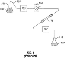
- FIG. 1 a block diagram of the essential elements of a conventional liquid chromatography (LC) system is provided.
- a reservoir 101 contains a solvent or mobile phase 102.
- Tubing 103 connects the mobile phase 102 in the reservoir 101 to a pump 105.
- the pump 105 is connected to a sample injection valve 110 which, in turn, is connected via tubing to a first end of a guard column (not shown).
- the second end of the guard column (not shown) is in turn connected to the first end of a primary column 115.
- the second end of the primary column 115 is then connected via tubing to a detector 117.
- the mobile phase 102 and the sample injected via injection valve 110 are expended into a second reservoir 118, which contains the chemical waste 119.
- the sample injection valve 110 is used to inject a sample of a material to be studied into the LC system.
- the mobile phase 102 flows through the tubing 103 which is used to connect the various elements of the LC system together.
- the sample When the sample is injected via sample injection valve 110 in the LC system, the sample is carried by the mobile phase through the tubing into the column 115.
- the column 115 contains a packing material which acts to separate the constituent elements of the sample.
- the sample After exiting the column 115, the sample (as separated via the column 115) then is carried to and enters a detector 117, which detects the presence or absence of various chemicals. The information obtained by the detector 117 can then be stored and used by an operator of the LC system to determine the constituent elements of the sample injected into the LC system.
- the various components are made of the synthetic polymer polyetheretherketone, which is commercially available under the trademark "PEEK” from Victrex.
- PEEK polymer polyetheretherketone
- the polymer PEEK has the advantage of providing a high degree of chemical inertness and therefore biocompatibility; it is chemically inert to most of the common solvents used in LC applications, such as acetone, acetonitrile, and methanol (to name a few).
- PEEK also can be machined by standard machining techniques to provide smooth surfaces. Those skilled in the art will appreciate that other polymers may be desirable in certain applications.
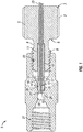
- Fluidic connection system 1 includes an actuator nut 2.
- Actuator nut 2 includes a first portion 6 proximate to the end 5 of the head of nut 2, and a non-tapered portion 8 proximate to the first portion 6.
- the actuator nut 2 also includes an externally threaded portion 9 having threads in a shape which corresponds to the shape of a first internally threaded portion 22 of a housing body 21. As shown in FIG.
- housing body 21 comprises a union, but those skilled in the art will appreciate that instead of a union, the housing body 21 could be any one of a wide variety of components in an LC, HPLC, UHPLC, or other AI system, including for example, any of the following: pumps, columns, filters, guard columns, injection valves and other valves, detectors, pressure regulators, reservoirs, and other fittings, such as unions, tees, crosses, adapters, splitters, sample loops, connectors, and the like.
- said externally threaded portion 9 of said actuator nut 2 is rotatably engaged with the internally threaded portion 22 of said housing body 21, thereby removably connecting said nut 2 to the housing body 21.
- the rotatable engagement of said externally threaded portion 9 of said nut 2 with the internally threaded portion 22 of said housing body 21 removably secures said actuator nut 2 to said housing body 21. (By turning the head portion of nut 2 in the opposite direction, a user can also disconnect the nut 2 from the housing body 21 .)
- axial force on the tube end face 15 is provided when the actuator nut 2 is rotated. As shown in FIG.
- Tube end face 15 is defined by an end face of an inner tube layer 13 and an end face of an outer tube tip 14.
- the outer tip 14, sometimes referred to herein as the tube tip 14 or as tip 14, has a first end 30 and a second end 31, with said tube end face 15 being proximate to the first end 30. Between said first end 30 and said second end 31, tube tip 14 surrounds an inner layer 13 of the tube.
- tube tip 14 is secured to a sleeve 12 of the tubing assembly by a retainer feature 16, which can be a feature or combination of features of a sleeve 12.
- a sleeve 12 surrounds the inner tubing layer 13.
- sleeve 12 surrounds said inner tubing layer 13 between the second end 31 of said tube tip 14 and the first end 3 of said actuator nut 2. As shown in FIG. 2 , sleeve 12 and inner tubing layer 13 extend and pass through a passageway through the axial length of the actuator nut 2, between the externally threaded portion 9 by means of a passageway 11.
- an internally threaded portion 22 on said housing body 21 is a matter of choice.
- the nut 2 could have an internally threaded portion (not shown) and the housing body 21 could have an externally threaded portion (not shown).
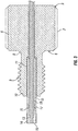
- the tubing inner layer 13 preferably has an outer layer surrounding at least a portion thereof.
- a tubing outer layer 19 can be seen. As shown in FIG. 3 , the outer layer 19 is located outside and around the inner tubing layer 13. In addition, a portion of the outer tubing layer 19 is located inside the sleeve 12, and an end portion of the outer tubing layer 19 extends beyond an end of the sleeve 12 and is located inside the overmolded tube tip 14. As also shown in FIG. 3 , a portion of the inner layer 13 extends beyond the end of the outer layer 19 in this embodiment.
- the sleeve 12 and outer tubing layer 19 can be secured to each other, such as by welding, adhesives, or by resin epoxies or other plastics, which can be located between the outside diameter of the outer layer 13 and the inner diameter of the sleeve 12. Securing the outer tubing layer 19 and the sleeve 12 helps prevent rotation of either independent of the other.
- the tubing layer 13 can comprise a number of different materials depending on the particular application, as that may involve a particular type of sample, a particular type of solvent, and/or a particular pressure range.
- the outer layer 19 of tube can comprise a metal, such as stainless steel (such as 316 stainless steel) or titanium, or a reinforced polymeric material, including composite or braided materials, such as polymeric materials that are reinforced or braided with carbon, carbon fibers, steel fibers, or the like.
- the metal temper can be varied to provide a balance between high pressure capability and tubing flexibility.
- the inner layer 13 can comprise a biocompatible polymer, such as polyetheretherketone (PEEK).
- polymer materials which may be used for the inner layer 13 include, but are not limited to, TEFLON®, TEFZEL®, DELRIN®, perfluoroalkoxy (PFA, also called perfluoroalkoxyethylene), fluorinated ethylene propylene (PEP), polytetrafluoroethylene (PETE), ETFE (a polymer of tetrafluoroethylene and ethylene), polyetherimide (PEI), polyphenylene sulfide (PPS), polypropylene, sulfone polymers, polyolefins, polyimides, other polyaryletherketones, other fluoropolymers, polyoxymethylene (POM), and others, depending on the foregoing factors or perhaps others.
- PFA perfluoroalkoxy
- PEP fluorinated ethylene propylene
- PETE polytetrafluoroethylene
- ETFE a polymer of tetrafluoroethylene and ethylene
- PEI polyetherimide
- the inner layer 13 may be coated with a material to increase strength, improve chemical resistance, improve temperature stability, or reduce permeability. Such coatings include, but are not limited to, metallization, polymeric coating, silicon-based coatings, and carbon-based coatings. Additionally, in certain embodiments the inner layer may be heat treated to improve properties such as crystallinity, chemical resistance, or permeability. Those skilled in the art will appreciate that, although shown and described herein as a single layer, the inner layer 13 of the tube may actually comprise two or more layers if desired.
- the final tube may be treated to further improve the performance, including heat treatment or annealing to strengthen the polymer components, or pressurizing, with or without added heat, to allow the inner layer to conform to the outer layer.
- a mandrel can be used in the inner diameter of the inner layer to preserve the passageway.
- Actuator nut 2, inner tubing layer 13, sleeve 12, and retainer feature 16 may be embodied in a variety of configurations.
- overmolded tube tip 14 is secured to the sleeve 12 by retainer feature 16.
- the retainer feature 16 has a protrusion which extends away from the inner layer 13 of the tube and towards the outer diameter of outer layer 14.
- the retainer feature 16 extends into a portion of the overmolded tube tip 14. Retainer feature 16 prevents the overmolded tube tip 14 from disengaging from the sleeve 12 and inner tubing layer 13.
- Retainer feature 16 also helps prevent the overmolded tube tip 14 from slipping while radial torque is being applied to the actuator nut 2 and axial force is being applied to the tube end face 15.
- the retainer feature 16 may be of different configurations. For example, more than one retainer feature 16 may be used (not shown). Alternatively, the retainer feature 16 may be of a different shape or size than suggested by FIG. 3 . Alternatively, the retainer feature 16 may be substituted by alternate means of securing the overmolded tube tip 14 to the sleeve 12, such as by means of an adhesive or by means of welding the overmolded tube tip 14 to the sleeve 12.
- actuator nut 2 preferably has a circular shape, and the exterior surface of the head portion of said actuator nut 2 has a plurality of splines 7 spaced around the head of the nut 2. While those skilled in the art will appreciate the advantages of a circular-shaped actuator nut 2, those skilled in the art will also appreciate that the actuator nut 2, and/or the head of the nut 2, may have a non-circular shape, such as a box shape (not shown), a hexagonal shape (not shown), or other shapes.
- the exterior surface of the actuator nut 2 may be flat (not shown) or cross-hatched (not shown), instead of characterized by splines 7.
- a variety of actuator nut 2 shapes and exterior surfaces may be used such that said actuator nut 2 may be easily gripped and manually rotated by an operator.
- the sleeve 12, inner tubing layer 13, and outer tubing layer 19 can be adapted to fit at least partially into a passageway 11.
- Inner tubing layer 13 is preferably comprised of a biocompatible material such as synthetic polymer polyetheretherketone, which is commercially available under the trademark PEEKTM from VTCTREX®.
- the outer layer 19 is preferably metal, such as stainless steel.
- Overmolded tube tip 14 can also comprise PEEKTM in this particular embodiment.
- inner tubing layer 13 and said overmolded tube tip 14 may be comprised of other polymer materials, including for example TEFLON®, TEFZEL®, DELRIN®, perfluoroalkoxyethylene (PFA), polytetrafluoroethylene (PETE), polyetherimide (PEI), polyphenylene sulfide (PPS), polypropylene, polyolefins, polyimides, or polyoxymethylene (POM).
- Either or both Inner tubing layer 13 and overmolded tube tip 14 may alternatively be comprised of carbon-fiber or steel-fiber materials that are interwoven with polymer materials, such as carbon-fiber PEEKTM.
- Either or both inner tubing layer 13 and overmolded tube tip layer 14 may alternatively be comprised of a nano-composite material.
- actuator nut 2 is comprised of a metal, such as, for example, stainless steel.
- a metal such as, for example, stainless steel.
- the actuator nut 2 may be comprised of other materials such as titanium, fused silica, or a reinforced rigid polymer material (e.g ., a carbon-fiber PEEKTM or other metal-braided polymer material). More rigid polymer materials may be more desirable in some applications, since stainless steel has some drawbacks in biological environments. For example, components in a biological fluid can attach to stainless steel, and stainless steel ions may leak into said fluid-both events having the potential to obscure measurements in liquid chromatography and other analytic chemistry applications.
- FIG. 5 provides an enlarged view of the cross-section of the combination of the inner layer 13 of the tube, the outer layer 19 of the tubing, and the sleeve 12.
- a passageway 24 extends along the longitudinal axis of the inner tubing layer 13 (and also outer tubing layer 19 ).
- a fluid or gas may be run through said passageway 24.
- the tube has an end face or surface 15 which is substantially flat.
- the tube end face 15 may have other shapes, such as a rounded or dimpled surface (not shown).
- a flat or substantially flat surface 15 is believed to be sufficient for purposes of creating an effective seal with the port end face 26, but other shapes or configurations of end face 15 may be used so long as the surfaces of the tube end face 15 and the port end face 35 are adapted to form a seal when engaged with one another. Other such embodiments are discussed below in connection with FIGS. 6A , 6B , and 6C .
- sleeve 12 is comprised of a metal, such as, for example, stainless steel.
- the sleeve 12 and/or outer tubing layer 19 may be comprised of steel or other materials such as titanium, fused silica, or a reinforced, rigid polymer material (e.g ., carbon-fiber PEEKTM, steel-braided TEFLON®).
- a reinforced, rigid polymer material e.g ., carbon-fiber PEEKTM, steel-braided TEFLON®.
- rigid polymer materials may be more desirable in some applications, since stainless steel has some drawbacks in biological environments, as is described above.
- FIG. 5 additional features of the tubing assembly are shown in an enlarged cross-section view.
- Retention features 16 and 17, for example, are shown in more detail.
- the retention feature 16 is a portion of sleeve 12 and is located at the end of the sleeve 12 which is closest to the face 15 defined by the end of the inner tube layer 13 and outer tube layer 14.
- Retention feature 16 is a protrusion or extension of sleeve 12 that provides a lip at the end of sleeve 12.
- the outward edge of the lip 16 is located further from the longitudinal axis of the inner layer 13 than an adjacent portion 17 of the sleeve 12.
- the combination of features 16 and 17 help hold the outer layer 14 once attached to sleeve 12 and thus keep the combination of inner layer 13, outer layer 14, and sleeve 12 from being detached from one another.
- the recessed portion 40 can be a conically-shaped or parabollicaly shaped recess, such that the end of sleeve 12 with the recessed portion provides an opening with a diameter greater than that of the passageway through the sleeve 12.
- the recessed portion 40 thus makes it easier to insert an end of the combined inner layer 13 and outer layer 19 into the passageway through the sleeve 12 for easier and faster manufacturing of the tubing assembly comprising inner layer 13, outer layer 19, and the sleeve 12.
- recessed portion 40 provides more flexibility to the tubing assembly once manufactured, because a user can more easily bend the portion of the inner layer 13 that extends out of the passageway of the sleeve 12 at the end opposite the end of the assembly at which surface 15 is located.
- sleeve 12 and outer layer 19 can be secured together.
- sleeve 12 comprises a metal (such as stainless steel)
- outer tubing layer 19 comprises a metal (such as stainless steel)
- sleeve 12 and outer layer 19 are secured together by welding (or by crimping or swaging) at or near portion 40 of sleeve 12.
- the tube tip 14 can be overmolded onto an end portion of the inner tubing layer 13, the outer tubing layer 19, and sleeve 12.
- the inner tube 13 and outer tube 19 may be inserted through the passageway extending through the sleeve 12 so that the first ends of both the inner tube layer 13 and outer tube layer 19 extend a predetermined distance from the first end of the sleeve 12.
- the combination of the inner tube 13, outer tubing 19, and the sleeve 12 in this configuration can then have the outer tip 14 overmolded onto the combination, thereby forming the portion of the tubing assembly which comprises the inner layer 13 of the tube, the outer layer 19 of the tube, the sleeve 12, and overmolded tube tip 14.
- the tube tip 14 is molded onto and over the inner layer 13, the outer layer 19, and the sleeve 12 by the process of injection molding.
- processes may be used, such as casting and welding, and may be selected depending on the materials selected for the inner layer 13, the outer layer 19, and the tube tip 14.
- the surface 15 of the first end of the tubing as defined by the combination of the end of the inner layer 13 and the end of the tube tip 14 may be further finished, such as by cutting the first end of the tubing, polishing the first end of the tubing, or machining, with such processes performed to obtain a substantially flat surface 15 defined by the first ends of the inner layer 13 and the tube tip 14.
- FIGS. 6A , 6B , and 6C alternative embodiments of a tubing assembly in accordance with the present disclosure are shown. Like numerals are used for the tip 14, inner tubing layer 13, sleeve 12, and outer tubing layer 19 in FIGS. 6A , 6B , and 6C for ease of reference.
- a tubing assembly 60 is shown.
- the tubing assembly 60 includes an inner tubing layer 13, and outer tubing layer 19, a sleeve 12, and also a tubing tip 14.
- the tubing tip 14 in FIG. 6A has portions 14a and 14b which are angled from the outer diameter of the tip 14 towards the longitudinal axis of the tubing assembly 60.
- This configuration reduces the surface area of the surface 15 defined by the ends of the inner layer 13 and the tip 14 which is adapted to contact a face in a flat-bottomed port. It is believed that by reducing the surface area of the seal, we also are able to reduce the force required to obtain a seal.
- a tubing assembly 61 includes an inner tubing layer 13, a sleeve 12, an outer tubing layer 19, and also a tip 14. As shown in FIG. 6B , the end of the inner tubing layer 13 is not flush with the end of the tip 14, thus leaving a gap 14c defined by the inner diameter of the tip 14.
- the surface 15 at one end of the tubing assembly 61 that is adapted to contact a surface in a flat-bottomed port is defined by the surface at the end of the tip 14 and not the end of the inner tubing layer 13. This configuration also reduces the surface area of the tubing assembly which is adapted to contact and seal with a flat-bottomed port.
- the tubing assembly 62 includes an inner tubing layer 13, a sleeve 12, an outer tubing layer 19, and a tip portion 14.
- the end of the tip portion 14 has portions 14d and 14e which include a "stepped" shape in which an outer portion extends towards the longitudinal axis of the tubing assembly 62 and then an angled portion extends from the step portion towards the end of the tip 14 and towards the longitudinal axis of the tubing assembly 62.
- This embodiment also helps reduce the surface area of the surface 15 defined by the combination of the end of the inner tubing layer 13 and the inner portion of the end of the tip 14 defined by the stepped end portions 14d and 14e.
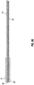
- FIGs. 7A-C A further embodiment is shown in FIGs. 7A-C .
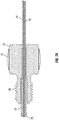
- the embodiment 70 of FIG. 7A also includes an actuator nut 70, comprising a head portion 71 at a first end thereof and a threaded portion 76 near a second end thereof, wherein the an external threaded portion 76 is configured to interact with an internally threaded connection 22, in a housing 21, best shown in FIG. 7C .
- the nut defines a passageway therethrough sized and shaped to contain a liner tubing 75 and a reinforcement tubing 74, wherein the liner tubing 75 can be concentrically contained with the reinforcement tubing 74.
- a portion of the passageway proximate and at least partially contained with the externally threaded portion 76 is also sized to contain a transfer tubing 72.
- the reinforcement tubing 74, the liner tubing 75 and the transfer tubing 72 extend out of the passageway through the second end of the nut 71 and terminate at tube end face 78.
- the transfer tubing 72 can be secured to the reinforcement tubing 74 by swaging or crimping onto the tubing with mechanical force radially or by any appropriate means known to those skilled in the art that allows for axial forces resulting from the fluid pressure reacted through the transfer tubing 72 and reinforcement tubing 74, such as welding, for example.
- This configuration (shown in FIG. 7D ) allows the tip 73 to be compressed between the reinforcement tubing 74 and a port bottom, which aids in creating a fluidic seal and prevents dead volume.
- the liner tubing 75 can be secured in the reinforcement tubing by an interference fit formed by feeding liner tubing 75 with an outer diameter greater than the internal diameter of reinforcement tubing 72 through the reinforcement tubing 72, thereby providing a tight interference fit, or such as by feeding liner tubing 75 through reinforcement tubing 75 and then either increasing the outer diameter of the liner tubing 75 or decreasing the inner diameter of the reinforcement tubing 72, or by other means known to those skilled in the art.
- the device further comprises a tip 73.
- the reinforcement tubing 74, the liner tubing 75 and the transfer tubing 72 extend out the second end of the nut 71 and terminate in a tube end face 78, in proximity to each other at a distance from the second end of the nut, configured to extend into a housing 21 through and past an internally threaded portion as described above.
- the tip 73 is disposed at the terminal end and is positioned to contact a face of a port extended into the housing 21 as shown in FIG. 7C .
- the nut 71 is reversibly connected to the housing by threading the external threads into a housing and reversibly connecting a port to the opposite end of the housing, a face seal is established between the tip and the bottom of the port without the use of ferrules to grip the tubing.
- the fitting assembly nut 71 drives against the bearing surface of the transfer tubing 72 to push the sealing surface of the tip 73 into and against the port bottom.
- the tip seal to the liner tubing 75 is created by an interference fit created by the internal diameter of the tip being smaller than the outside diameter of the tubing that requires the liner tubing 75 to be drawn into the tip 73.
- the tip 73 can be slid into position against the reinforcement tubing 74.
- the transfer tubing 72 is slid over the outside of the tip 73 and crimped into place by means known to those skilled in the art including, for example, the presence of angled surfaces that interact to create a taper lock interference fit.
- the assembly instead uses the interference between the components to retain the integrity of the seal and connection system.
- the reinforcement tubing 74 and transfer tubing 72 can be metal, selected from but not limited to stainless steel, steel, or titanium.
- the tip 73 and liner tubing 75 can be made of softer materials, including polymers such as PEEK, carbon filled PAEK, PEEK, PEKK, FEP, PFA, ETFE, or PTFE, for example.
- the nut 71 can comprise either one or more metals such as stainless steel, aluminum, titanium, or nickel, for example, or one or more polymers as appropriate for the intended use in particular systems, and with particular fluids.
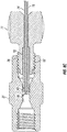
- FIG. 7B A closer view of the fitting including the tubing and passageway is shown in FIG. 7B .
- the liner tubing and reinforcement tubing are drawn into the interior diameter of the tip to provide an interference fit.
- the transfer tubing can then be slid over the outside of the tip and in place, or held in place by other appropriate methods known in the art.
- the fitting is shown as it interacts with a housing body 21 for connection to a port.
- the tubing end face 78 extends through the threaded portion 76 and into the housing body past the mated threaded portions 76 and 22. The terminal end face can thus be pressed against a port end face to create a seal.
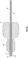
- FIG. 7D An alternate embodiment of the fitting of FIG. 7A-C is shown in FIG. 7D .
- the second end of the transfer tubing 72 includes an angled internal face portion 77 and the tip 73 includes an oppositely angled outer face portion 79 to facilitate easier insertion of the tip 73 into the transfer tubing 72 by a user.
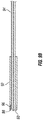
- FIGs. 8A-C An embodiment including an alternate tip 83 is shown in FIGs. 8A-C .
- all common items are numbered the same as in the embodiment shown in FIGs. 7A-C .
- the tip 83 shown in FIGs. 8A-C is no longer captured by the transfer tubing 72 with an interference fit.
- This embodiment instead uses the transfer tubing 72 to drive against the tip 83 during assembly to create a face seal on a sealing surface in a port and the surfaces contacting the transfer tubing 72.
- the tip 83 is drawn onto the tubing and utilizes an interference fit to create a seal between the liner tubing 75 and tip 83. All of the components of the embodiment of FIGs. 8A-C can be manufactured from the same materials as the embodiment shown in FIGs. 7A-C .
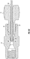
- FIG. 8B An enlarged view of the embodiment of FIG. 8A is shown in FIG. 8B .
- the transfer tubing 72 is shortened from the tube face end 78 such that the tip abuts the terminal end of the transfer tube 72, while the liner tube 74 and reinforcement tube 75 are contained in the inner diameter of the tip 83.
- FIG. 8C A view of a fitting as described in FIG. 8A connected to a housing body 21 is shown in FIG. 8C . As describe above, when the nut is driven into the housing, the tip 83 at the tube face 78 is forced against a port face by the transfer tubing 72 to create a face seal.
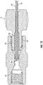
- FIGs. 9A-C Another embodiment of a connection assembly is shown in FIGs. 9A-C .
- This embodiment does not include a liner tubing.
- the embodiment uses the sealing of the tip 93 in a port bottom along with sealing of the tip 93 to a conduit tubing 94.
- the transfer tubing 92 translates the load from the rotational torque of the nut when applied by an operator to both sealing areas of the tip 93.
- the transfer tubing 92 in this embodiment can be made of a more durable or less resilient material such as a metal material, with stainless steel being an exemplary material, and the transfer tubing includes a pocket portion 96. There is interference between the outside diameter of the tip 93 and the pocket portion 96 in the transfer tubing 92.
- the interference is effective to retain the tip 93 on the conduit tubing 94 during assembly and disassembly.
- the face of the tip is effective to form a seal with a port sealing face as shown in FIG. 9C .
- the use of a stainless steel transfer tubing 92 allows for the use of higher pressures. Pressures in excess of 15,000, 20,000, and 25,000 psi have been achieved in test samples of this embodiment without leaking.
- the conduit tubing 94 and transfer tubing 92 can be manufactured from and comprise stainless steel tubing, for example, or can be made from other metals as known to those skilled in the art.
- the tip 93 can include one or more polymers such as PEEK, carbon fiber reinforced PEEK, PEKK, FEP, PFA, ETFE, or PTFE, for example.
- the fitting can be either a metal such as stainless steel, aluminum, or titanium, for example, or one or more polymers depending on system requirements.
- FIG. 9A An enlarged view of the tubing as shown in FIG. 9A is shown in FIG. 9B , in which the tip 93 can be seen extending into the pocket portion 96 effective to be held against the conduit tubing 94 and forming a tube face end effective to form a face seal with a port seal face as shown in FIG. 9C .
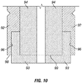
- FIGS. 10-13 Additional embodiments of the disclosed connection assemblies that can be used to form a face seal with various flat bottomed ports or fixtures as required and that do not include a liner tubing are shown in FIGS. 10-13 .
- the connector assembly shown in FIG. 10 includes a transfer tubing 92 surrounding the conduit tubing 94 as in the embodiment shown in FIG. 9A . There is again interference in this embodiment between the outside diameter of the tip 93 and the pocket portion 96 and the transfer tubing 92. It can be seen in this embodiment that the end face 98 of the transfer tube is flush with the end face 99 of the conduit tubing 94.
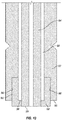
- FIG. 11 An additional embodiment is shown in which the end face 99 of the conduit tubing 94 extends beyond the end face 98 of the transfer tubing 92.
- the pocket portion 96 and the tip in this embodiment extend from the inner diameter to the outer diameter of the conduit tubing 94 and is not disposed between the end of the conduit tubing and the port (not shown).
- FIG. 12 A further embodiment is shown in which the end face 99 of the conduit tubing 94 extends even further out of the transfer tubing 92.
- Such connection assemblies are shown to indicate that the disclosed embodiments can be altered or configured to effectively seal with a variety of connectors or ports as needed, or to provide an effective seal at various pressures and volumes.
- the embodiments shown in FIGS. 10-12 do not include a liner tubing.
- the embodiments use the sealing of the tip 93 in a port bottom along with sealing of the tip 93 to a conduit tubing 94.
- the transfer tubing 92 translates the load from the rotational torque of the nut when applied by an operator to both sealing areas of the tip 93.
- the transfer tubing 92 in these embodiments can be made of a more durable or less resilient material such as a metal material, with stainless steel being an exemplary material, and the transfer tubing includes a pocket portion 96. There is interference between the outside diameter of the tip 93 and the pocket portion 96 in the transfer tubing 92.
- the interference is effective to retain the tip 93 on the conduit tubing 94 during assembly and disassembly.
- the face of the tip is effective to form a seal with a port sealing face.
- the use of a stainless steel transfer tubing 92 allows for the use of higher pressures.
- the conduit tubing 94 and transfer tubing 92 can be manufactured from and comprise stainless steel tubing, for example, or can be made from other metals as known to those skilled in the art.
- the tip 93 can include one or more polymers such as PEEK, carbon fiber reinforced PEEK, PEKK, FEP, PFA, ETFE, PEEKsil, or PTFE, for example.
- the conduit tubing 94 can be a capillary tube, such as a capillary made of silica, fused glass, PEEKsil (fused silica with a sheath of polyetheretherketone), the transfer tubing 94 can be made of a polymer such as one or more of those noted above, and/or the tip 93 can be made of metal, such as stainless steel.
- the fitting can be either a metal such as stainless steel, aluminum, or titanium, for example, or one or more polymers depending on system requirements.
- FIG. 13 is an enlarged cross-sectional view of an end of the assembly.
- an assembly is shown which includes conduit tubing 94, transfer tubing 92, and a tip 93.
- the assembly includes a sleeve 97.
- the sleeve 97 includes pockets 96 in which a portion of the tip 93 is located.
- the end face 99 of conduit tubing 94 is flush with an end face of the tip 93, and the end faces of tip 93 and conduit tubing 94 are adapted to abut a port (not shown in FIG. 13 ).
- FIG. 13 is an enlarged cross-sectional view of an end of the assembly.
- an assembly which includes conduit tubing 94, transfer tubing 92, and a tip 93.
- the assembly includes a sleeve 97.
- the sleeve 97 includes pockets 96 in which a portion of the tip 93 is located.
- the end face 99 of conduit tubing 94 is flush with an end face of the tip
- an end face 95 of the sleeve 97 is flush with the end face 98 of the transfer tubing 92.
- the transfer tubing 92, conduit tubing 94, sleeve 97, and tip 93 can each be made of various materials, including those noted above for the embodiments shown in FIGS. 10-12 , including polymeric, metal, and ceramic materials, and may be varied depending on the intended application of the assembly, such as the pressures involved, the solvents and fluids involved, and the like.
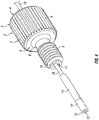
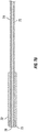
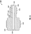
- an alternative nut 1001 is shown.
- the nut 1001 can be used in any of the foregoing embodiments.
- the nut 1001 has a first end portion 1005, as well as an externally threaded portion 1010, a lower portion 1015, a knurled portion 1020, and a top portion 1025 at the second end of the nut 1001.
- the nut 1001 has openings 1026 and 1028 at its top and bottom (or second and first) ends, respectively.
- the openings 1026 and 1028 are open to a passageway 1030 (shown in FIGS. 15 and 16 ) extending longitudinally through the nut 1001.
- the nut 1001 also has a slotted, grooved or split portion 1050.
- the slot or groove 1050 extends the longitudinal length of the nut 1001. Radially, the groove 1050 also extends from the outer surface of the nut 1001 to the passageway 1030 (not shown in FIG. 14 ) extending along the longitudinal axis of the nut 1001.
- the groove or slot 1050 of the nut 1001 provides an advantage because it allows an operator to route a tube (such as described above in various embodiments) through an analytical instrument system and/or its various components, then add the nut 1001 to make up a connection with the fitting assembly after the tube is roughly in place.
- a tube such as described above in various embodiments
- the space for the various components can be limited and fairly tight, and in such situations having the nut captivated on the tube assembly can make it difficult to route the assembly to the proper location to make up a connection.
- having the slot 1050 on the nut 1001 allows for easier location and for easier and faster replacement of tubing in many situations.
- the groove 1050 also may allow for easier use of the nut 1001 when the nut 1001 is rotated in engagement with a port, such as a port in an LC, HPLC, UHPLC, or other AI system, or other component, such as in such a system (which could be a union, pump, column, filter, guard column, injection valve or other valve, detector, pressure regulator, reservoir, or another fitting, such as a tee, cross, adapter, splitter, sample loop, connector, or the like) to make a fluidic connection, such as when used in connection with the embodiments of this disclosure described above.
- a port such as a port in an LC, HPLC, UHPLC, or other AI system, or other component, such as in such a system (which could be a union, pump, column, filter, guard column, injection valve or other valve, detector, pressure regulator, reservoir, or another fitting, such as a tee, cross, adapter, splitter, sample loop, connector, or the like) to make a fluidic connection
- the nut 1001 could have an internally threaded portion (not shown) adapted to engage with an externally threaded portion of a port or other component such as those listed, or could be otherwise configured to provide axial loading.
- the nut 1001 can be made of a metal, such as, for example, stainless steel.
- a metal such as, for example, stainless steel.
- the nut 1001 may be comprised of other materials such as titanium, fused silica, or a reinforced rigid polymer material (e.g., a carbon-fiber PEEKTM or other metal-braided polymer material). More rigid polymer materials may be more desirable in some applications, since stainless steel has some drawbacks in biological environments. For example, components in a biological fluid can attach to stainless steel, and stainless steel ions may leak into said fluid-both events having the potential to obscure measurements in liquid chromatography and other analytic chemistry applications.
- the nut 1001 thus can comprise biocompatible materials, such as polyetheretherketone (PEEK), which are generally inert with respect to biological materials.
- PEEK polyetheretherketone
- the slot 1050 of the nut 1001 need not run the entire longitudinal length of the nut 1001.
- a plurality of slots can be provided instead of a single slot 1050.
- the nut 1001 could have a top slot at the top end 1025 of the nut 1001 and also a bottom slot at the bottom end 1005 of the nut 1001.
- FIG. 15 a cross-sectional view of the nut 1001 is shown. Like features in FIGS. 14-16 have the same numerals for ease of reference.
- the nut 1001 has a passageway 1030 extending through the nut 1001 generally along the longitudinal axis of the nut 1001.
- the first end portion 1005, externally threaded portion 1010, lower portion 105, knurled portion 1020, and second end 1025 correspond to those portions as shown in FIG. 14 .
- the nut 1001 has an interior seating portion 1040 proximate towards the first end 1005 of the nut 1001, with the interior seating portion 1040 open to opening 1028.
- the interior seating portion 1040 is adapted to receive and removably hold a tube assembly comprising a tube and a liner sleeve, transfer tube, or other sleeve (not shown in FIG. 15 ) in place.
- a tube assembly comprising a tube and a liner sleeve, transfer tube, or other sleeve (not shown in FIG. 15 ) in place.
- any of the sleeves described above including without limitation the sleeve 12 or sleeve 92, can be adapted to fit within the interior seating portion 1040 of the nut 1001.
- the interior seating portion 1040 at one end has an end portion 1045. As shown in FIG. 15 , the interior seating portion 1040 has a wider diameter than that of other portions of the passageway 1030 in the nut 1001. The end portion 1045 provides a seat at one end of the interior seating portion 1040.
- the seat at the end portion 1045 of nut 1001 allows a compressive force to be applied by the end portion 1045 against a sleeve held within the interior seating portion 1040 of the nut 1001, such as when the nut 1001 is rotated relative to a port or other component to make up a fluidic connection or fitting assembly, such as described above with respect to other embodiments, thereby transferring the compressive force to the end of the tube assembly as it abuts a face in a port or other component.
- FIG. 16 a different cross-sectional view of the nut 1001 is provided.
- the numbering in FIG. 16 uses like numerals to refer to the same features as shown in FIGS. 14 and 15 for convenience.
- a flared portion 1060 located at the first end of the nut 1001.
- the portion 1060 provides an opening 1028 with a wider diameter than the interior seating portion 1040, thus allowing a user to more easily and quickly insert a tubing assembly (such as a combination comprising a tube and a sleeve as described above) into the nut 1001.
- a tubing assembly such as a combination comprising a tube and a sleeve as described above
- tubing and also the components of a fitting assembly or connection system, used in many analytical instrument systems for fluidic connections can be very small.
- the components used in many analytical instrument systems can vary, and often need to be changed or replaced, such as replacing columns, pumps, injection valves, and so forth, whether when switching from one particular application of the system for one type of analysis to another or substantially re-organizing the system and its components.
- an operator can more easily install or disconnect a fluidic connection in an AI system. For example, to make a connection, an operator can first locate or insert the nut 1001 in a port, and then easily insert a portion of the tubing or tube assembly through the slot 1050 of the nut 1001, and then tighten the nut 1001 in the port to form a sealed connection. Similarly, an operator, when disconnecting a fluidic connection, can simply rotate the nut 1001 relative to the port to loosen the fitting assembly and, without removing the nut 1001 from the port, remove the tubing by pulling the tubing through the slot 1050.
- tubing assembly and a fitting assembly which can be used for making one or more connections in any system that utilizes a face seal (such as a flat-bottomed port), and can withstand the fluid pressures required for ultra-high pressure liquid chromatography (UHPLC) and other analytical instrument applications.
- a face seal such as a flat-bottomed port
- UHPLC ultra-high pressure liquid chromatography
- PES PEEK lined steel
- fitting and tubing assembly configurations described and shown in this disclosure focus on only one end of the tubing and fitting assembly, but the present disclosure may be used in embodiments as a complete fluidic connection between two components, for example, such as a connection including two nuts and tubing with two ends such as described and shown in this disclosure for providing a fluid connection between any two points in an analytical instrument system or other system.
- the tubing in accordance with the present disclosure may have an outside diameter (OD) in the range of from about 1/64 inches to about 1 ⁇ 4 inch, or about 1/64, 1/32, 1/16, 1/8 or 1 ⁇ 4 of an inch in diameter inclusive, and may have an inner diameter (ID) of from about 0.001 to about 0.085 inches, or about 0.001, 0.002, 0.006, 0.010, 0.015, 0.020, 0.025, 0.030, 0.060, or 0.085 inches, inclusive.
- OD outside diameter
- ID inner diameter
- the assembly described and shown in this disclosure is capable of UHPLC pressures (>18,000 psi) at finger-tight torque values of 2-3 in*lbs, for example.
- the assemblies are also flexible and capable of multiple connection uses prior to failure. It is believed that the fitting assembly of the present disclosure is able to translate rotational torque directly to axial force to generate the seal with a flat-bottom port which will hold at very high pressures like those noted.
- the fitting assembly of the present disclosure does not require any ferrules or other similar sealing mechanisms, is easy to use by an operator, and can generate a seal at high pressures with torque levels that do not require any tools and are easily obtained by most users.
Applications Claiming Priority (5)
| Application Number | Priority Date | Filing Date | Title |
|---|---|---|---|
| US201462067739P | 2014-10-23 | 2014-10-23 | |
| US201562127276P | 2015-03-02 | 2015-03-02 | |
| US201562168491P | 2015-05-29 | 2015-05-29 | |
| EP15853047.7A EP3209920B1 (de) | 2014-10-23 | 2015-10-23 | Fluidisches verbindungssystem mit flächendichtung |
| PCT/US2015/057238 WO2016065334A1 (en) | 2014-10-23 | 2015-10-23 | Face-sealing fluidic connection system |
Related Parent Applications (2)
| Application Number | Title | Priority Date | Filing Date |
|---|---|---|---|
| EP15853047.7A Division EP3209920B1 (de) | 2014-10-23 | 2015-10-23 | Fluidisches verbindungssystem mit flächendichtung |
| EP15853047.7A Division-Into EP3209920B1 (de) | 2014-10-23 | 2015-10-23 | Fluidisches verbindungssystem mit flächendichtung |
Publications (1)
| Publication Number | Publication Date |
|---|---|
| EP3828455A1 true EP3828455A1 (de) | 2021-06-02 |
Family
ID=55761670
Family Applications (2)
| Application Number | Title | Priority Date | Filing Date |
|---|---|---|---|
| EP15853047.7A Active EP3209920B1 (de) | 2014-10-23 | 2015-10-23 | Fluidisches verbindungssystem mit flächendichtung |
| EP21150378.4A Withdrawn EP3828455A1 (de) | 2014-10-23 | 2015-10-23 | Fluidisches verbindungssystem mit flächendichtung |
Family Applications Before (1)
| Application Number | Title | Priority Date | Filing Date |
|---|---|---|---|
| EP15853047.7A Active EP3209920B1 (de) | 2014-10-23 | 2015-10-23 | Fluidisches verbindungssystem mit flächendichtung |
Country Status (4)
| Country | Link |
|---|---|
| US (2) | US10655761B2 (de) |
| EP (2) | EP3209920B1 (de) |
| JP (2) | JP6767973B2 (de) |
| WO (1) | WO2016065334A1 (de) |
Families Citing this family (23)
| Publication number | Priority date | Publication date | Assignee | Title |
|---|---|---|---|---|
| DE102009022368C5 (de) | 2009-05-22 | 2020-12-17 | Dionex Softron Gmbh | Steckereinheit und Verbindungssystem für das Verbinden von Kapillaren, insbesondere für die Hochleistungsflüssigkeitschromatographie |
| GB2482175B (en) * | 2010-07-23 | 2016-01-13 | Agilent Technologies Inc | Fitting element with bio-compatible sealing |
| US11187360B2 (en) | 2014-10-23 | 2021-11-30 | Idex Health & Science Llc | Fluidic connector assembly for quick connect/disconnect |
| EP3163298B1 (de) | 2015-10-30 | 2023-12-27 | Dionex Softron GmbH | Kapillarrohrverbindung |
| US10174871B2 (en) | 2016-03-04 | 2019-01-08 | Valco Instruments Company, L.P. | Zero dead volume fitting assembly |
| EP3244205A1 (de) * | 2016-05-12 | 2017-11-15 | Möller Medical GmbH | Kapillaranschlusseinheit für analysegeräte und medizinische geräte |
| EP3469246B1 (de) * | 2016-06-13 | 2022-02-09 | Idex Health & Science LLC | Fluidverbinderanordnung für schnellverbindung/schnelllösung |
| KR20190033514A (ko) | 2016-07-21 | 2019-03-29 | 워터스 테크놀로지스 코포레이션 | 손가락 조임 고압 유체 커플링 |
| US10551360B2 (en) * | 2016-10-11 | 2020-02-04 | Bruker Daltonik Gmbh | Low dead-volume connector for fluid chromatography |
| US11054054B2 (en) | 2016-12-09 | 2021-07-06 | Idex Health & Science Llc | High pressure valve with multi-piece stator assembly |
| US10384151B2 (en) | 2016-12-09 | 2019-08-20 | Idex Health & Science Llc | High pressure valve with two-piece stator assembly |
| US10520477B2 (en) | 2016-12-09 | 2019-12-31 | Idex Health & Science Llc | High pressure valve with multi-piece stator assembly |
| US10690563B2 (en) * | 2017-01-17 | 2020-06-23 | Waters Technologies Corporation | Systems, methods, and devices for detecting leaks in a chromatography system |
| JP6825995B2 (ja) * | 2017-06-02 | 2021-02-03 | 株式会社ブリヂストン | 射出成形金型、樹脂部材、及び、樹脂製品の製造方法 |
| JP6725082B2 (ja) * | 2017-09-14 | 2020-07-15 | 株式会社島津製作所 | Esiスプレイヤー |
| US11041581B2 (en) * | 2018-02-26 | 2021-06-22 | Valco Instruments Company, L.P. | Zero dead volume fitting assembly |
| EP3561504B1 (de) | 2018-04-25 | 2023-01-04 | Idex Health & Science LLC | Hochdruckventil mit mehrteiliger statoranordnung |
| US20210389286A1 (en) * | 2018-11-09 | 2021-12-16 | Western Sydney University | A chromatography component |
| KR102362653B1 (ko) * | 2019-06-21 | 2022-02-14 | 샘찬에너지(주) | 튜브 피팅 조립 방법 |
| WO2021030439A1 (en) * | 2019-08-14 | 2021-02-18 | Waters Technologies Corporation | Fitting for fluidic coupling in a chromatography system |
| WO2021250948A1 (ja) * | 2020-06-09 | 2021-12-16 | 株式会社島津製作所 | 樹脂チューブ接続装置 |
| US20220269016A1 (en) * | 2021-02-22 | 2022-08-25 | Digilab Inc. | Cell printer coil connector |
| JP2022169189A (ja) * | 2021-04-27 | 2022-11-09 | 株式会社島津製作所 | バイオイナート配管 |
Citations (17)
| Publication number | Priority date | Publication date | Assignee | Title |
|---|---|---|---|---|
| US2935339A (en) * | 1958-03-31 | 1960-05-03 | Mckiernan Terry Corp | Readily applicable, shock proof end fitting for heavy duty flexible tubing |
| US5472598A (en) | 1994-04-15 | 1995-12-05 | Upchurch Scientific, Inc. | Connection assembly for liquid chromatography columns |
| US5525303A (en) | 1993-08-12 | 1996-06-11 | Optimize Technologies, Inc. | Integral fitting and filter of an analytical chemical instrument |
| US5730943A (en) | 1993-08-12 | 1998-03-24 | Optimize Technologies, Inc. | Integral fitting and filter of an analytical chemical instrument |
| US6056331A (en) | 1996-09-12 | 2000-05-02 | The Regents Of The University Of California | Zero dead volume tube to surface seal |
| US6056031A (en) | 1995-11-30 | 2000-05-02 | Nippei Toyama Corporation | System and method for processing ingots |
| US6095572A (en) | 1998-01-20 | 2000-08-01 | Optimize Technologies, Inc. | Quarter turn quick connect fitting |
| US20050269264A1 (en) | 2004-06-04 | 2005-12-08 | Adam Fermier | Chromatography system with gradient storage and method for operating the same |
| US20070283746A1 (en) | 2004-01-23 | 2007-12-13 | Waters Investments Limited | Sample Injector System for Liquid Chromatography |
| US7311502B2 (en) | 2001-12-21 | 2007-12-25 | Waters Investments Limited | Method for using a hydraulic amplifier pump in ultrahigh pressure liquid chromatography |
| US20110298210A1 (en) * | 2008-12-02 | 2011-12-08 | Dionex Softron Gmbh | Plug unit and connection system for connecting capillary tubes, especially for high-performance liquid chromatography |
| US20120024411A1 (en) | 2010-07-16 | 2012-02-02 | Idex Health & Science Llc | Biocompatible Tubing for Liquid Chromatography Systems |
| US20120061955A1 (en) | 2009-05-22 | 2012-03-15 | Hermann Hochgraeber | Plug unit and connection system for connecting capillary tubes, especially for high-performance liquid chromatography |
| US20130043677A1 (en) | 2010-04-30 | 2013-02-21 | James David Gibson | Tube and pipe end cartridge seal |
| US20130233053A1 (en) * | 2012-03-12 | 2013-09-12 | Idex Health & Science Llc | Torque Limited Fitting |
| US20130341260A1 (en) * | 2010-12-20 | 2013-12-26 | Agilent Technologies, Inc. | Sealed fluidic component comprising a composite material of different paek materials |
| US8696038B2 (en) | 2012-03-02 | 2014-04-15 | Idex Health & Science Llc | Flat bottom fitting assembly |
Family Cites Families (39)
| Publication number | Priority date | Publication date | Assignee | Title |
|---|---|---|---|---|
| CA961888A (en) | 1971-04-15 | 1975-01-28 | Leonard P. Spontelli | Tube fitting |
| GB1434013A (en) | 1972-04-27 | 1976-04-28 | Fields R E | Connectors for tubes or conduits |
| US4083702A (en) | 1976-07-19 | 1978-04-11 | The Perkin-Elmer Corporation | Chromatographic column fittings |
| US4529230A (en) | 1982-02-26 | 1985-07-16 | Supelco, Inc. | Capillary tubing and small rod connector |
| JPS59193351A (ja) | 1983-04-18 | 1984-11-01 | Tokyo Rika Kikai Kk | 液体クロマトグラフの流路接続装置 |
| US4915427A (en) | 1987-12-10 | 1990-04-10 | Crawford Fitting Co. | Coupling device for heavy-walled tubular members |
| AU5852590A (en) | 1989-07-03 | 1991-01-17 | Commonwealth Scientific And Industrial Research Organisation | Polymeric tube fitting |
| US5169120A (en) | 1990-02-27 | 1992-12-08 | Computer Chemical Systems, Inc. | Zero dead volume variable restrictor |
| CN2087340U (zh) | 1991-01-09 | 1991-10-23 | 中国科学院大连化学物理研究所 | 高效液相色谱柱通用接头 |
| DE4114765A1 (de) | 1991-05-06 | 1992-11-12 | Kronwald Separationstechnik Gm | Universalschlauch- oder rohranschluss |
| US5601785A (en) | 1991-12-23 | 1997-02-11 | Microsensor Technology, Inc. | Connector for detachable column cartridge for gas chromatograph |
| US5306052A (en) * | 1992-12-15 | 1994-04-26 | Megushion Kevin D | Tubing union with a torque transfer fitting |
| US5423581A (en) | 1993-03-31 | 1995-06-13 | Salyers; Marshall L. | Low carryover fitting and method for coupling tubing to a device using the same |
| US5651885A (en) | 1994-04-15 | 1997-07-29 | Schick; Hans G. | Column for liquid chromatography |
| US5651776A (en) * | 1995-03-22 | 1997-07-29 | Angiodynamics, Inc. | Luer-type connector |
| US5595406A (en) | 1995-11-30 | 1997-01-21 | Hewlett-Packard Co. | Capillary tubing connector |
| US6273478B1 (en) | 1999-03-30 | 2001-08-14 | The Regents Of The University Of California | Microfluidic interconnects |
| US6494500B1 (en) | 1999-05-12 | 2002-12-17 | Geoff Todosiev | Universal high pressure liquid connector |
| DE19958475A1 (de) | 1999-11-30 | 2001-06-13 | Parker Hannifin Gmbh | Rohrverbindung und Verfahren zu ihrer Herstellung |
| AUPQ646900A0 (en) | 2000-03-27 | 2000-04-20 | Sge International Pty Ltd | Metal ferrule for capillary tubing |
| FR2811403B1 (fr) | 2000-07-05 | 2002-08-16 | Commissariat Energie Atomique | Raccordement d'un micro-tube a une structure |
| US7014222B1 (en) | 2001-03-05 | 2006-03-21 | Rheodyne, Llc | Tube connection system |
| DE10393203B4 (de) * | 2002-09-12 | 2017-12-14 | Waters Technologies Corp. (N.D.Ges.D. Staates Delaware) | Kapillarverbindungsfassung und Verfahren zum Halten einer Kapillarverrohrung |
| US6926313B1 (en) | 2003-04-02 | 2005-08-09 | Sandia National Laboratories | High pressure capillary connector |
| US7497483B2 (en) | 2004-04-22 | 2009-03-03 | Swagelok Company | Fitting for tube and pipe with cartridge |
| US8240719B2 (en) | 2004-07-21 | 2012-08-14 | Parker-Hannifin Corporation | Adaptor and method for converting standard tube fitting/port to push-to-connect tube fitting/port |
| US7316777B2 (en) | 2005-01-28 | 2008-01-08 | Valco Instruments Co., Inc. | Compression fitting nut with interlocked ferrule |
| US20080309076A1 (en) | 2005-02-25 | 2008-12-18 | Waters Investments Limited | Device and Method for a Fluid-Tight Connection |
| US8006367B1 (en) | 2007-10-24 | 2011-08-30 | Best John W | Fitting to secure tubing within a CPI port |
| DE202008002211U1 (de) | 2008-02-15 | 2009-03-26 | Weh, Erwin | Hochdruckverschraubung |
| US8201854B2 (en) | 2008-06-02 | 2012-06-19 | Optimize Technologies, Inc. | Hybrid ferrule |
| WO2010000324A1 (en) | 2008-07-04 | 2010-01-07 | Agilent Technologies, Inc. | Sealing ferrule assembly exerting grip on capillary |
| JP2010048409A (ja) | 2008-07-23 | 2010-03-04 | Daikin Ind Ltd | 食い込み式管接続構造、弁、食い込み式管継手及び冷凍装置 |
| GB2482175B (en) | 2010-07-23 | 2016-01-13 | Agilent Technologies Inc | Fitting element with bio-compatible sealing |
| WO2012116753A1 (en) * | 2011-03-03 | 2012-09-07 | Agilent Technologies, Inc. | Coated capillary with remelted coating for front sided sealing |
| DE102011050037B3 (de) | 2011-05-02 | 2012-06-14 | Dionex Softron Gmbh | Steckereinheit und Verbindungssystem zum Verbinden von Kapillaren, insbesondere für die Hochleistungsflüssigkeitschromatographie |
| US9334989B2 (en) | 2011-06-20 | 2016-05-10 | Waters Technologies Corporation | Low carryover high pressure fluidic fitting |
| CH705381A1 (de) * | 2011-08-15 | 2013-02-15 | Moeller Medical Gmbh | Rohr beinhaltend Metallmantel mit Kunststoff-Inlay zur Verwendung bei Nieder- und Hochdruckanwendungen, insbesondere als HPLC-Säule. |
| DE102012110991B4 (de) * | 2012-11-15 | 2017-01-05 | Dionex Softron Gmbh | Steckereinheit und Verbindungssystem zum Verbinden von Kapillaren, insbesondere für die Hochleistungsflüssigkeitschromatographie |
-
2015
- 2015-10-23 US US14/922,041 patent/US10655761B2/en active Active
- 2015-10-23 EP EP15853047.7A patent/EP3209920B1/de active Active
- 2015-10-23 WO PCT/US2015/057238 patent/WO2016065334A1/en active Application Filing
- 2015-10-23 JP JP2017521536A patent/JP6767973B2/ja active Active
- 2015-10-23 EP EP21150378.4A patent/EP3828455A1/de not_active Withdrawn
-
2020
- 2020-04-23 US US16/856,751 patent/US20200292108A1/en not_active Abandoned
- 2020-09-18 JP JP2020157212A patent/JP2020201288A/ja not_active Ceased
Patent Citations (18)
| Publication number | Priority date | Publication date | Assignee | Title |
|---|---|---|---|---|
| US2935339A (en) * | 1958-03-31 | 1960-05-03 | Mckiernan Terry Corp | Readily applicable, shock proof end fitting for heavy duty flexible tubing |
| US5525303A (en) | 1993-08-12 | 1996-06-11 | Optimize Technologies, Inc. | Integral fitting and filter of an analytical chemical instrument |
| US5730943A (en) | 1993-08-12 | 1998-03-24 | Optimize Technologies, Inc. | Integral fitting and filter of an analytical chemical instrument |
| US5472598A (en) | 1994-04-15 | 1995-12-05 | Upchurch Scientific, Inc. | Connection assembly for liquid chromatography columns |
| US6056031A (en) | 1995-11-30 | 2000-05-02 | Nippei Toyama Corporation | System and method for processing ingots |
| US6056331A (en) | 1996-09-12 | 2000-05-02 | The Regents Of The University Of California | Zero dead volume tube to surface seal |
| US6095572A (en) | 1998-01-20 | 2000-08-01 | Optimize Technologies, Inc. | Quarter turn quick connect fitting |
| US7311502B2 (en) | 2001-12-21 | 2007-12-25 | Waters Investments Limited | Method for using a hydraulic amplifier pump in ultrahigh pressure liquid chromatography |
| US20070283746A1 (en) | 2004-01-23 | 2007-12-13 | Waters Investments Limited | Sample Injector System for Liquid Chromatography |
| US20050269264A1 (en) | 2004-06-04 | 2005-12-08 | Adam Fermier | Chromatography system with gradient storage and method for operating the same |
| US20110298210A1 (en) * | 2008-12-02 | 2011-12-08 | Dionex Softron Gmbh | Plug unit and connection system for connecting capillary tubes, especially for high-performance liquid chromatography |
| US20120061955A1 (en) | 2009-05-22 | 2012-03-15 | Hermann Hochgraeber | Plug unit and connection system for connecting capillary tubes, especially for high-performance liquid chromatography |
| US20130043677A1 (en) | 2010-04-30 | 2013-02-21 | James David Gibson | Tube and pipe end cartridge seal |
| EP2564104A2 (de) | 2010-04-30 | 2013-03-06 | Parker-Hannifin Corporation | Hochdruckrohrveschraubungen, dichtungen und werkzeuge für die erstellung von endflächen |
| US20120024411A1 (en) | 2010-07-16 | 2012-02-02 | Idex Health & Science Llc | Biocompatible Tubing for Liquid Chromatography Systems |
| US20130341260A1 (en) * | 2010-12-20 | 2013-12-26 | Agilent Technologies, Inc. | Sealed fluidic component comprising a composite material of different paek materials |
| US8696038B2 (en) | 2012-03-02 | 2014-04-15 | Idex Health & Science Llc | Flat bottom fitting assembly |
| US20130233053A1 (en) * | 2012-03-12 | 2013-09-12 | Idex Health & Science Llc | Torque Limited Fitting |
Also Published As
| Publication number | Publication date |
|---|---|
| EP3209920A4 (de) | 2018-08-22 |
| JP2017531805A (ja) | 2017-10-26 |
| WO2016065334A1 (en) | 2016-04-28 |
| US20200292108A1 (en) | 2020-09-17 |
| EP3209920A1 (de) | 2017-08-30 |
| US10655761B2 (en) | 2020-05-19 |
| US20160116088A1 (en) | 2016-04-28 |
| JP6767973B2 (ja) | 2020-10-14 |
| JP2020201288A (ja) | 2020-12-17 |
| EP3209920B1 (de) | 2021-04-21 |
Similar Documents
| Publication | Publication Date | Title |
|---|---|---|
| US20200292108A1 (en) | Face-Sealing Fluidic Connection System | |
| US10738918B2 (en) | Manifold connection assembly | |
| US10962146B2 (en) | Biocompatible tubing for liquid chromatography systems | |
| JP6257097B2 (ja) | トルク制限接続具 | |
| JP5745047B2 (ja) | 超高圧液体クロマトグラフィ用の連結組立体 | |
| JP5940179B2 (ja) | 接続組立体 | |
| JP2014507009A (ja) | 自己解放フェルール付き高圧接続具 | |
| JP7359820B2 (ja) | 迅速接続/接続解除のための流体接続アセンブリ | |
| US11085904B2 (en) | Column having a compression-limited assembly |
Legal Events
| Date | Code | Title | Description |
|---|---|---|---|
| PUAI | Public reference made under article 153(3) epc to a published international application that has entered the european phase |
Free format text: ORIGINAL CODE: 0009012 |
|
| STAA | Information on the status of an ep patent application or granted ep patent |
Free format text: STATUS: THE APPLICATION HAS BEEN PUBLISHED |
|
| AC | Divisional application: reference to earlier application |
Ref document number: 3209920 Country of ref document: EP Kind code of ref document: P |
|
| AK | Designated contracting states |
Kind code of ref document: A1 Designated state(s): AL AT BE BG CH CY CZ DE DK EE ES FI FR GB GR HR HU IE IS IT LI LT LU LV MC MK MT NL NO PL PT RO RS SE SI SK SM TR |
|
| STAA | Information on the status of an ep patent application or granted ep patent |
Free format text: STATUS: REQUEST FOR EXAMINATION WAS MADE |
|
| 17P | Request for examination filed |
Effective date: 20211201 |
|
| RBV | Designated contracting states (corrected) |
Designated state(s): AL AT BE BG CH CY CZ DE DK EE ES FI FR GB GR HR HU IE IS IT LI LT LU LV MC MK MT NL NO PL PT RO RS SE SI SK SM TR |
|
| STAA | Information on the status of an ep patent application or granted ep patent |
Free format text: STATUS: THE APPLICATION HAS BEEN WITHDRAWN |
|
| 18W | Application withdrawn |
Effective date: 20220311 |