EP3828450B1 - Electric valve - Google Patents
Electric valve Download PDFInfo
- Publication number
- EP3828450B1 EP3828450B1 EP19841217.3A EP19841217A EP3828450B1 EP 3828450 B1 EP3828450 B1 EP 3828450B1 EP 19841217 A EP19841217 A EP 19841217A EP 3828450 B1 EP3828450 B1 EP 3828450B1
- Authority
- EP
- European Patent Office
- Prior art keywords
- pipe
- rectifying member
- valve
- diameter portion
- small diameter
- Prior art date
- Legal status (The legal status is an assumption and is not a legal conclusion. Google has not performed a legal analysis and makes no representation as to the accuracy of the status listed.)
- Active
Links
- 239000003507 refrigerant Substances 0.000 claims description 29
- 230000002093 peripheral effect Effects 0.000 claims description 5
- 230000000694 effects Effects 0.000 description 5
- 238000005516 engineering process Methods 0.000 description 4
- 238000003466 welding Methods 0.000 description 4
- 230000002159 abnormal effect Effects 0.000 description 3
- 239000002826 coolant Substances 0.000 description 3
- 239000002184 metal Substances 0.000 description 3
- 229910052751 metal Inorganic materials 0.000 description 3
- 230000005514 two-phase flow Effects 0.000 description 3
- RYGMFSIKBFXOCR-UHFFFAOYSA-N Copper Chemical compound [Cu] RYGMFSIKBFXOCR-UHFFFAOYSA-N 0.000 description 2
- 229910052802 copper Inorganic materials 0.000 description 2
- 239000010949 copper Substances 0.000 description 2
- 239000012530 fluid Substances 0.000 description 2
- 238000004519 manufacturing process Methods 0.000 description 2
- 238000003825 pressing Methods 0.000 description 2
- 230000009172 bursting Effects 0.000 description 1
- 238000005520 cutting process Methods 0.000 description 1
- 238000009826 distribution Methods 0.000 description 1
- 230000007613 environmental effect Effects 0.000 description 1
- 230000001747 exhibiting effect Effects 0.000 description 1
- 238000002474 experimental method Methods 0.000 description 1
- 238000010438 heat treatment Methods 0.000 description 1
- 239000007788 liquid Substances 0.000 description 1
- 238000000034 method Methods 0.000 description 1
- 238000004080 punching Methods 0.000 description 1
- 238000005057 refrigeration Methods 0.000 description 1
- 230000001105 regulatory effect Effects 0.000 description 1
- 238000007789 sealing Methods 0.000 description 1
- 229910001220 stainless steel Inorganic materials 0.000 description 1
- 239000010935 stainless steel Substances 0.000 description 1
- 238000011144 upstream manufacturing Methods 0.000 description 1
- 238000010792 warming Methods 0.000 description 1
Images


Classifications
-
- F—MECHANICAL ENGINEERING; LIGHTING; HEATING; WEAPONS; BLASTING
- F16—ENGINEERING ELEMENTS AND UNITS; GENERAL MEASURES FOR PRODUCING AND MAINTAINING EFFECTIVE FUNCTIONING OF MACHINES OR INSTALLATIONS; THERMAL INSULATION IN GENERAL
- F16K—VALVES; TAPS; COCKS; ACTUATING-FLOATS; DEVICES FOR VENTING OR AERATING
- F16K47/00—Means in valves for absorbing fluid energy
- F16K47/08—Means in valves for absorbing fluid energy for decreasing pressure or noise level and having a throttling member separate from the closure member, e.g. screens, slots, labyrinths
-
- F—MECHANICAL ENGINEERING; LIGHTING; HEATING; WEAPONS; BLASTING
- F16—ENGINEERING ELEMENTS AND UNITS; GENERAL MEASURES FOR PRODUCING AND MAINTAINING EFFECTIVE FUNCTIONING OF MACHINES OR INSTALLATIONS; THERMAL INSULATION IN GENERAL
- F16K—VALVES; TAPS; COCKS; ACTUATING-FLOATS; DEVICES FOR VENTING OR AERATING
- F16K27/00—Construction of housing; Use of materials therefor
- F16K27/02—Construction of housing; Use of materials therefor of lift valves
-
- F—MECHANICAL ENGINEERING; LIGHTING; HEATING; WEAPONS; BLASTING
- F16—ENGINEERING ELEMENTS AND UNITS; GENERAL MEASURES FOR PRODUCING AND MAINTAINING EFFECTIVE FUNCTIONING OF MACHINES OR INSTALLATIONS; THERMAL INSULATION IN GENERAL
- F16K—VALVES; TAPS; COCKS; ACTUATING-FLOATS; DEVICES FOR VENTING OR AERATING
- F16K31/00—Actuating devices; Operating means; Releasing devices
- F16K31/02—Actuating devices; Operating means; Releasing devices electric; magnetic
- F16K31/04—Actuating devices; Operating means; Releasing devices electric; magnetic using a motor
-
- F—MECHANICAL ENGINEERING; LIGHTING; HEATING; WEAPONS; BLASTING
- F25—REFRIGERATION OR COOLING; COMBINED HEATING AND REFRIGERATION SYSTEMS; HEAT PUMP SYSTEMS; MANUFACTURE OR STORAGE OF ICE; LIQUEFACTION SOLIDIFICATION OF GASES
- F25B—REFRIGERATION MACHINES, PLANTS OR SYSTEMS; COMBINED HEATING AND REFRIGERATION SYSTEMS; HEAT PUMP SYSTEMS
- F25B41/00—Fluid-circulation arrangements
- F25B41/30—Expansion means; Dispositions thereof
- F25B41/31—Expansion valves
-
- F—MECHANICAL ENGINEERING; LIGHTING; HEATING; WEAPONS; BLASTING
- F25—REFRIGERATION OR COOLING; COMBINED HEATING AND REFRIGERATION SYSTEMS; HEAT PUMP SYSTEMS; MANUFACTURE OR STORAGE OF ICE; LIQUEFACTION SOLIDIFICATION OF GASES
- F25B—REFRIGERATION MACHINES, PLANTS OR SYSTEMS; COMBINED HEATING AND REFRIGERATION SYSTEMS; HEAT PUMP SYSTEMS
- F25B2500/00—Problems to be solved
- F25B2500/12—Sound
Definitions
- the present invention relates to a motor valve used in a refrigeration cycle of an air conditioner, a refrigerator, or the like.
- the motor valves are used to change a direction and a flow rate of a refrigerant flowing inside according to the desired function.
- the refrigerant flows into the valve body in a gas-liquid two-phase state, and sudden pressure fluctuations occur when air bubbles contained in the refrigerant, especially large-diameter air bubbles, pass through an orifice, and its accompanying pressure wave propagates to pipes, causing abnormal noise.
- Patent Documents 1 and 2 In order to prevent such abnormal noise from being generated, as shown in Patent Documents 1 and 2, a technique has been proposed in which bubbles in the two-phase flow are fined to prevent the generation of the pressure waves due to the bursting of the bubbles when passing through the orifice, by arranging a rectifying member such as a porous plate at the port of the motor valve and the pipe connection portion, and the refrigerant being passed through the small hole thereof.
- a rectifying member such as a porous plate
- the rectifying member is interposed and fixed between an outer wall of a valve body and an end of the pipe, a distance between the rectifying member and a valve chamber is short, and the effect of eliminating the air bubbles was not sufficient. That is, shape and dimensions of the air bubbles fined by the small holes of a rectifying plate are stabilized after a certain period of time in the refrigerant. According to the applicant's experiment, it is desirable that the dimensions of the inner diameter of the pipe are set so as to flow in the pipe even after passing through the rectifying plate in order to prevent the growth of the air bubbles.
- the rectifying plate is arranged between the end of the pipe and the outer wall of the valve body, the refrigerant that has passed through the rectifying plate immediately flows into the valve chamber from the inside of the pipe, and the air bubbles tend to grow in the valve chamber due to changes in pressure and flow direction at that time.
- cone-shaped rectifying member As a configuration for effectively fining the air bubbles in the refrigerant, it is also considered to increase the number of small holes through which the refrigerant passes even if the pipes have the same inner diameter.
- cone-shaped rectifying member when used in the conventional technologies, there arises a problem that a tip of the cone protruding toward the valve body interferes with the valve body or a sufficient distance between the rectifying member and the valve body cannot be secured.
- the present invention has been proposed to solve the problems of the conventional technologies described above, and an objective is to provide the motor valve which can easily and surely fix the rectifying member in the middle of the pipe and has excellent quietness.
- a motor valve according to the present invention includes the following structures.
- the rectifying member can be fixed reliably at a position away from the valve body with good positioning accuracy by a simple structure.
- FIG. 1 is a cross-sectional view illustrating a configuration of the motor valve. This motor valve is arranged in various directions in actual use, however in the present description, a positional relationship of each member will be described according to the direction shown in FIG. 1 .
- the motor valve adjusts an opening degree of an orifice 8 provided in a valve body 3 by moving a rod-shaped valve shaft 2 up and down inside a space defined by a cup-shaped cylindrical member 1 called a can and the valve body 3 and controls a flow rate of the passing fluid.
- a rotor of a stepping motor that drives the valve shaft 2 is provided inside the cylindrical member 1, and a coil of the stepping motor is arranged outside the cylindrical member 1.
- the motor valve rotates the rotor by energizing the coil and reciprocates the valve shaft 2 coupled to the rotor in the axial direction to open and close the valve.
- the stator, coil, and the like provided outside the cylindrical member 1 are omitted.
- the valve body 3 having a valve chamber 3a inside is provided below the cylindrical member 1.
- a first port 4 and a second port 5, which are paths for a fluid such as a refrigerant, are connected to the valve chamber 3a, respectively, and the first port 4 and the second port 5 are communicated with each other via the valve chamber 3a.
- a first pipe 6 and a second pipe 7 that connect the motor valve and external devices are fixed to the first port 4 and the second port 5, respectively.
- the refrigerant flows from the second pipe 7 arranged in the lateral direction toward the first pipe 6 extending downward.
- a cylindrical-shaped orifice 8 is fitted into the first port 4 and fixed by means such as welding.
- a valve seat is formed around a central opening of the orifice 8, and the flow rate is controlled by the width of the gap between the valve seat portion and a tip of the valve shaft 2.
- An end of the first pipe 6 is fitted into the outside of the orifice 8 and fixed by means such as welding.
- the second pipe 7 has a large diameter portion 7a on an external supply side and a small diameter portion 7b on a motor valve side, and a step portion 7c provided at a boundary portion between the large diameter portion 7a and the small diameter portion 7b.
- the second pipe 7 is fixed to the valve body 3 with an end of the small diameter portion 7b inserted into the second port 5.
- a position of the step portion 7c is provided at a position separated by an inner diameter dimension ( ⁇ A) or more of the small diameter portion 7b from an end portion 7ba on the small diameter portion 7b side of the second pipe 7.
- a rectifying member 9 is fixed to a boundary portion of the large diameter portion 7a with the step portion 7c.
- the rectifying member 9 is inserted into the large diameter portion 7a in a state where the axial movement of the second pipe 7 is restricted by the step portion 7c. That is, according to the configuration of the present embodiment, the distance L from the end portion 7ba on the small diameter portion 7b side of the second pipe 7 to the rectifying member 9 positioned on the step portion 7c may be arbitrarily set. Then, by setting the distance L to ⁇ A or more, a regrowth of the air bubbles in the refrigerant subdivided by the rectifying member 9 can be suppressed. On the other hand, when the distance L is too long, since the fine bubbles grow up towards the valve chamber 3a, t is desirable that the distance L is 10 times or less of ⁇ A.
- the rectifying member 9 is a columnar-shaped member that is coaxial with the second pipe 7 and closes the second pipe 7.
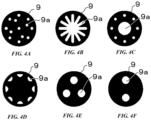
- the rectifying member 9 is provided with one or a plurality of openings 9a communicating in the axial direction of the second pipe 7.
- a shape of the opening 9a is a slit shape or a small hole shape for fining the air bubbles in the refrigerant, and for example, those shown in FIGS. 4A to 4F can be adopted.
- An optimum shape of the opening 9a is selected according to the property of easily generating the two-phase flow of the refrigerant, the flow velocity, the viscosity, the diameter of the pipe, and the like.
- a length of the columnar-shaped rectifying member 9 or a wall thickness of a disk when the rectifying member 9 is formed into the disk shape is appropriately selected depending on the nature of the refrigerant and the diameter of the pipe.
- a rectifying member 9 is formed by a cutting processing or a pressing processing.
- the second pipe 7 and the rectifying member 9 are provided with positioning means for fixing the two.
- the positioning means is a swaging portion 10 that deforms the wall portion of the second pipe 7 facing the rectifying member 9 in the inner diameter direction of the second pipe 7 and tightens the rectifying member 9 from surroundings and fix it to the wall portion of the second pipe 7.
- the rectifying member 9 In order to fix the rectifying member 9 in the second pipe 7 in the present embodiment, first, with the rectifying member 9 held at a tip of the elongated rod-shaped jig of the second pipe 7, the rectifying member 9 is inserted from an end opening of the large diameter portion 7a to a position where it abuts on the step portion 7c, and the rectifying member 9 is positioned. Next, by pressing and deforming a wall surface of the second pipe 7 from an outer circumference of the large diameter portion 7a, the rectifying member 9 is interposed between the inner wall surface of the second pipe 7 and the step portion 7c by the swaging portion 10. After that, by pulling out the jig from the second pipe 7, the fixing of the rectifying member 9 to the second pipe 7 is completed. After that, the second pipe 7 is fixed to the second port 5 of the valve body 3 by means such as welding.
- the motor valve of the present embodiment has the following effects.
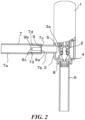
- a second embodiment will be described with reference to FIG.2 .
- the positioning means of the rectifying member 9 is different between the second embodiment and the first embodiment. That is, the rectifying member 9 of the second embodiment is composed of a disk-shaped metal plate such as stainless steel, and four elastic members 9b extending along the axial direction of the second pipe 7 toward the large diameter portion 7a are provided around the rectifying member.
- the elastic member 9b is biased in the outer peripheral direction of the second pipe 7.
- An engaging portion 9c protruding in the outer peripheral direction of the second pipe 7 is provided at a tip portion of the elastic member 9b.
- On an inner surface of the second pipe 7, a concave-shaped engaged portion 7d into which the engaging portion 9c is fitted is provided in a ring shape over the entire inner circumference of the second pipe 7.
- the rectifying member 9 can be fixed at a position in the middle of the second pipe 7, the same effect as that of the first embodiment is exhibited. Moreover, since the subsequent swaging work is not required just by inserting the rectifying member 9, the assembly work becomes simpler.
- the rectifying member 9 includes a frame portion 9d along the inner circumference of the second pipe 7 and a net 9e stretched over the frame portion 9d.
- the frame portion 9d includes an inner frame that fixes the edge of the net 9e so as not to fray, and a tubular outer frame that is fitted and fixed to the outer circumference thereof.
- a ring-shaped recess 9f is provided on the outer circumference of the tubular outer frame. The portion of the recess 9f on the net 9e side, that is, the portion on the small diameter portion 7b side has a tapered surface in which the small diameter portion 7b side is narrowed.
- the outer circumference of the net 9e is smaller than the small diameter portion 7b, and the net projects in a cone shape in the downstream direction of the refrigerant flowing in the second pipe 7 with respect to the frame portion 9d, that is, inside the small diameter portion 7b.
- the tip of the cone does not protrude from an end of the second pipe 7 on the small diameter portion 7b side, and does not protrude from the outer wall surface of the valve body 3.
- the net 9e may be a metal product such as a wire mesh or a punching metal, or a plastic product integrally molded with the frame portion 9d.
- a swaging portion 10 protruding toward the inner diameter side is provided in a ring shape on a portion of the second pipe 7 facing the rectifying member 9, and the protruding portion of the swaging portion 10 engages with the recess 9f of the frame portion 9d.
- the rectifying member 9 is inserted from the large diameter portion 7a side using the jig until it comes into contact with the step portion 7c. Then, the small diameter portion 7b side of the rectifying member 9 is positioned by the step portion 7c, and the protruding portion of the swaging portion 10 engages with the recess 9f of the frame portion 9d, so that the rectifying member 9 and the second pipe 7 are fixed.
- the small diameter portion 7b side of the recess 9f has a tapered surface, the convex portion of the swaging portion 10 fits smoothly into the recess 9f, however once fitted, the rectifying member 9 does not move to the large diameter portion 7a side.
- the frame portion 9d may be provided with the same elastic member 9b and engaging portion 9c as in the second embodiment, and be engaged with the engaged portion 7d provided on the inner wall surface of the second pipe 7, thus, the second pipe 7 and the rectifying member 9 may be fixed.
- the second pipe 7 may be deformed from the outer circumference and the frame portion 9d may be fixed by the swaging portion 10.
- the third embodiment having such configuration, in addition to exhibiting the same effects as those of the above-described embodiments, it becomes possible to use a cone-shaped rectifying member 9 having a large surface area and a large number of openings 9a. Therefore, in the third embodiment, a contact area between the rectifying member 9 and the refrigerant can be made large, and the air bubbles in the refrigerant can be effectively fined. Further, in the third embodiment, even if the cone of the rectifying member 9 protrudes greatly to the valve body 3 side, the position of the step portion 7c for fixing the rectifying member 9 may be provided at a position away from the wall surface of the valve body 3.
- the second pipe 7, but also the first pipe 6 or both pipes may be provided with the rectifying member 9.
- the large diameter portion 7a side may be fixed to the valve body 3.
- the upstream side of the refrigerant does not necessarily have to be the large diameter portion 7a, and when the fixing strength of the swaging portion 10 and the engagement strength between the engaging portion 9c and the engaged portion 7d are sufficient, refrigerant can also be flowed from the small diameter portion 7b side.
Landscapes
- Engineering & Computer Science (AREA)
- General Engineering & Computer Science (AREA)
- Mechanical Engineering (AREA)
- Physics & Mathematics (AREA)
- Thermal Sciences (AREA)
- Electrically Driven Valve-Operating Means (AREA)
- Valve Housings (AREA)
- Details Of Valves (AREA)
Applications Claiming Priority (2)
| Application Number | Priority Date | Filing Date | Title |
|---|---|---|---|
| JP2018139805A JP7029169B2 (ja) | 2018-07-25 | 2018-07-25 | 電動弁 |
| PCT/JP2019/028457 WO2020022214A1 (ja) | 2018-07-25 | 2019-07-19 | 電動弁 |
Publications (3)
| Publication Number | Publication Date |
|---|---|
| EP3828450A1 EP3828450A1 (en) | 2021-06-02 |
| EP3828450A4 EP3828450A4 (en) | 2022-04-27 |
| EP3828450B1 true EP3828450B1 (en) | 2024-05-29 |
Family
ID=69181547
Family Applications (1)
| Application Number | Title | Priority Date | Filing Date |
|---|---|---|---|
| EP19841217.3A Active EP3828450B1 (en) | 2018-07-25 | 2019-07-19 | Electric valve |
Country Status (4)
| Country | Link |
|---|---|
| EP (1) | EP3828450B1 (ja) |
| JP (1) | JP7029169B2 (ja) |
| CN (1) | CN112424519A (ja) |
| WO (1) | WO2020022214A1 (ja) |
Families Citing this family (2)
| Publication number | Priority date | Publication date | Assignee | Title |
|---|---|---|---|---|
| JP7511250B2 (ja) * | 2021-06-07 | 2024-07-05 | 株式会社不二工機 | 電動弁 |
| KR102531504B1 (ko) * | 2021-12-29 | 2023-05-11 | 주식회사 포스톤텍 | 통수량을 조절할 수 있는 상수도 급수용 정유량 조절밸브 |
Family Cites Families (12)
| Publication number | Priority date | Publication date | Assignee | Title |
|---|---|---|---|---|
| JPH0626738A (ja) * | 1992-07-08 | 1994-02-04 | Hitachi Ltd | 空気調和装置 |
| JP3738084B2 (ja) * | 1996-06-28 | 2006-01-25 | 三洋電機株式会社 | 空気調和装置 |
| JP3435621B2 (ja) * | 1996-10-08 | 2003-08-11 | 株式会社日立製作所 | 空気調和機 |
| JP3435626B2 (ja) * | 1997-07-02 | 2003-08-11 | 株式会社日立製作所 | 空気調和機 |
| JP4812348B2 (ja) | 2005-07-11 | 2011-11-09 | 株式会社不二工機 | 電動弁 |
| JP4925638B2 (ja) | 2005-10-14 | 2012-05-09 | 株式会社不二工機 | 電動弁 |
| JP2007162851A (ja) * | 2005-12-14 | 2007-06-28 | Fuji Koki Corp | 電動弁 |
| JP4563945B2 (ja) * | 2006-02-24 | 2010-10-20 | 太平洋工業株式会社 | 双方向定圧膨張弁及びその製造方法 |
| JP2008170055A (ja) | 2007-01-11 | 2008-07-24 | Daikin Ind Ltd | 消音装置及び消音装置の製造方法 |
| CN102650337B (zh) * | 2011-02-23 | 2015-02-18 | 株式会社鹭宫制作所 | 阀结构体以及具备该阀结构体的止回阀 |
| JP6194157B2 (ja) * | 2012-05-18 | 2017-09-06 | 株式会社不二工機 | 電動弁 |
| JP6938401B2 (ja) * | 2018-02-21 | 2021-09-22 | 株式会社鷺宮製作所 | 流量制御弁および冷凍サイクルシステム |
-
2018
- 2018-07-25 JP JP2018139805A patent/JP7029169B2/ja active Active
-
2019
- 2019-07-19 WO PCT/JP2019/028457 patent/WO2020022214A1/ja active Application Filing
- 2019-07-19 CN CN201980040456.1A patent/CN112424519A/zh active Pending
- 2019-07-19 EP EP19841217.3A patent/EP3828450B1/en active Active
Also Published As
| Publication number | Publication date |
|---|---|
| EP3828450A1 (en) | 2021-06-02 |
| EP3828450A4 (en) | 2022-04-27 |
| WO2020022214A1 (ja) | 2020-01-30 |
| JP2020016292A (ja) | 2020-01-30 |
| JP7029169B2 (ja) | 2022-03-03 |
| CN112424519A (zh) | 2021-02-26 |
Similar Documents
| Publication | Publication Date | Title |
|---|---|---|
| EP3828450B1 (en) | Electric valve | |
| CN106352139B (zh) | 电动阀以及冷冻循环系统 | |
| CN109114237A (zh) | 电动阀以及冷冻循环系统 | |
| KR200495690Y1 (ko) | 에어컨 시스템 및 그 전자 팽창 밸브 | |
| CN109296805A (zh) | 电动阀以及冷冻循环系统 | |
| JP2020034141A (ja) | 電動弁及び冷凍サイクルシステム | |
| EP1275916B1 (en) | Expansion valve | |
| CN109114284B (zh) | 电动阀以及冷冻循环系统 | |
| JP2016142335A (ja) | 絞り装置及び冷凍サイクル | |
| JP2007032979A (ja) | 冷凍サイクル装置 | |
| US9366342B2 (en) | Poppet valve with linear area gain | |
| JP2007032980A (ja) | 膨張弁 | |
| EP3991873A1 (en) | Flow path structure, check valve comprising same, and method for producing check valve | |
| JP2024038287A (ja) | 電動弁 | |
| JP4476757B2 (ja) | 弁装置および冷凍サイクル装置 | |
| JP6037958B2 (ja) | 流量制御弁及びヒートポンプ装置 | |
| JP2023118753A (ja) | 電動弁及び冷凍サイクルシステム | |
| JP2016142380A (ja) | 絞り装置及び冷凍サイクルシステム | |
| JP2008128603A (ja) | 電動膨張弁 | |
| JP7362555B2 (ja) | 逆止弁および冷凍サイクルシステム | |
| EP4067715A1 (en) | Power element and expansion valve using same | |
| JP2022019265A (ja) | 逆止弁および冷凍サイクルシステム | |
| EP2927546B1 (en) | Steam valve | |
| JP2021063529A (ja) | 電動弁及び冷凍サイクルシステム | |
| JP7299178B2 (ja) | 電動弁及び冷凍サイクルシステム |
Legal Events
| Date | Code | Title | Description |
|---|---|---|---|
| STAA | Information on the status of an ep patent application or granted ep patent |
Free format text: STATUS: THE INTERNATIONAL PUBLICATION HAS BEEN MADE |
|
| PUAI | Public reference made under article 153(3) epc to a published international application that has entered the european phase |
Free format text: ORIGINAL CODE: 0009012 |
|
| STAA | Information on the status of an ep patent application or granted ep patent |
Free format text: STATUS: REQUEST FOR EXAMINATION WAS MADE |
|
| 17P | Request for examination filed |
Effective date: 20210219 |
|
| AK | Designated contracting states |
Kind code of ref document: A1 Designated state(s): AL AT BE BG CH CY CZ DE DK EE ES FI FR GB GR HR HU IE IS IT LI LT LU LV MC MK MT NL NO PL PT RO RS SE SI SK SM TR |
|
| DAV | Request for validation of the european patent (deleted) | ||
| DAX | Request for extension of the european patent (deleted) | ||
| A4 | Supplementary search report drawn up and despatched |
Effective date: 20220325 |
|
| RIC1 | Information provided on ipc code assigned before grant |
Ipc: F25B 41/31 20210101ALI20220321BHEP Ipc: F16K 47/08 20060101ALI20220321BHEP Ipc: F16K 27/02 20060101ALI20220321BHEP Ipc: F16K 47/02 20060101ALI20220321BHEP Ipc: F16K 31/04 20060101ALI20220321BHEP Ipc: F16K 27/00 20060101AFI20220321BHEP |
|
| GRAP | Despatch of communication of intention to grant a patent |
Free format text: ORIGINAL CODE: EPIDOSNIGR1 |
|
| STAA | Information on the status of an ep patent application or granted ep patent |
Free format text: STATUS: GRANT OF PATENT IS INTENDED |
|
| INTG | Intention to grant announced |
Effective date: 20240110 |
|
| GRAS | Grant fee paid |
Free format text: ORIGINAL CODE: EPIDOSNIGR3 |
|
| GRAA | (expected) grant |
Free format text: ORIGINAL CODE: 0009210 |
|
| STAA | Information on the status of an ep patent application or granted ep patent |
Free format text: STATUS: THE PATENT HAS BEEN GRANTED |
|
| AK | Designated contracting states |
Kind code of ref document: B1 Designated state(s): AL AT BE BG CH CY CZ DE DK EE ES FI FR GB GR HR HU IE IS IT LI LT LU LV MC MK MT NL NO PL PT RO RS SE SI SK SM TR |
|
| REG | Reference to a national code |
Ref country code: CH Ref legal event code: EP |
|
| REG | Reference to a national code |
Ref country code: IE Ref legal event code: FG4D |
|
| REG | Reference to a national code |
Ref country code: DE Ref legal event code: R096 Ref document number: 602019053040 Country of ref document: DE |