EP3828124B1 - Hebekran mit automatischem bestimmungssystem der einscherung - Google Patents
Hebekran mit automatischem bestimmungssystem der einscherung Download PDFInfo
- Publication number
- EP3828124B1 EP3828124B1 EP20209155.9A EP20209155A EP3828124B1 EP 3828124 B1 EP3828124 B1 EP 3828124B1 EP 20209155 A EP20209155 A EP 20209155A EP 3828124 B1 EP3828124 B1 EP 3828124B1
- Authority
- EP
- European Patent Office
- Prior art keywords
- lifting
- reeving
- configuration
- block
- double
- Prior art date
- Legal status (The legal status is an assumption and is not a legal conclusion. Google has not performed a legal analysis and makes no representation as to the accuracy of the status listed.)
- Active
Links
Images


Classifications
-
- B—PERFORMING OPERATIONS; TRANSPORTING
- B66—HOISTING; LIFTING; HAULING
- B66D—CAPSTANS; WINCHES; TACKLES, e.g. PULLEY BLOCKS; HOISTS
- B66D3/00—Portable or mobile lifting or hauling appliances
- B66D3/04—Pulley blocks or like devices in which force is applied to a rope, cable, or chain which passes over one or more pulleys, e.g. to obtain mechanical advantage
- B66D3/043—Block and tackle system with variable number of cable parts
-
- B—PERFORMING OPERATIONS; TRANSPORTING
- B66—HOISTING; LIFTING; HAULING
- B66C—CRANES; LOAD-ENGAGING ELEMENTS OR DEVICES FOR CRANES, CAPSTANS, WINCHES, OR TACKLES
- B66C13/00—Other constructional features or details
- B66C13/16—Applications of indicating, registering, or weighing devices
-
- B—PERFORMING OPERATIONS; TRANSPORTING
- B66—HOISTING; LIFTING; HAULING
- B66C—CRANES; LOAD-ENGAGING ELEMENTS OR DEVICES FOR CRANES, CAPSTANS, WINCHES, OR TACKLES
- B66C23/00—Cranes comprising essentially a beam, boom, or triangular structure acting as a cantilever and mounted for translatory of swinging movements in vertical or horizontal planes or a combination of such movements, e.g. jib-cranes, derricks, tower cranes
- B66C23/18—Cranes comprising essentially a beam, boom, or triangular structure acting as a cantilever and mounted for translatory of swinging movements in vertical or horizontal planes or a combination of such movements, e.g. jib-cranes, derricks, tower cranes specially adapted for use in particular purposes
- B66C23/26—Cranes comprising essentially a beam, boom, or triangular structure acting as a cantilever and mounted for translatory of swinging movements in vertical or horizontal planes or a combination of such movements, e.g. jib-cranes, derricks, tower cranes specially adapted for use in particular purposes for use on building sites; constructed, e.g. with separable parts, to facilitate rapid assembly or dismantling, for operation at successively higher levels, for transport by road or rail
-
- B—PERFORMING OPERATIONS; TRANSPORTING
- B66—HOISTING; LIFTING; HAULING
- B66C—CRANES; LOAD-ENGAGING ELEMENTS OR DEVICES FOR CRANES, CAPSTANS, WINCHES, OR TACKLES
- B66C23/00—Cranes comprising essentially a beam, boom, or triangular structure acting as a cantilever and mounted for translatory of swinging movements in vertical or horizontal planes or a combination of such movements, e.g. jib-cranes, derricks, tower cranes
- B66C23/88—Safety gear
- B66C23/90—Devices for indicating or limiting lifting moment
- B66C23/905—Devices for indicating or limiting lifting moment electrical
-
- B—PERFORMING OPERATIONS; TRANSPORTING
- B66—HOISTING; LIFTING; HAULING
- B66C—CRANES; LOAD-ENGAGING ELEMENTS OR DEVICES FOR CRANES, CAPSTANS, WINCHES, OR TACKLES
- B66C23/00—Cranes comprising essentially a beam, boom, or triangular structure acting as a cantilever and mounted for translatory of swinging movements in vertical or horizontal planes or a combination of such movements, e.g. jib-cranes, derricks, tower cranes
- B66C23/02—Cranes comprising essentially a beam, boom, or triangular structure acting as a cantilever and mounted for translatory of swinging movements in vertical or horizontal planes or a combination of such movements, e.g. jib-cranes, derricks, tower cranes with non-adjustable and non-inclinable jibs mounted solely for slewing movements
- B66C23/022—Pivot axis common with column
Definitions
- the invention relates to a lifting crane comprising a boom and a double-reeving lifting device shaped to distribute and lift a load along the boom.
- It relates more particularly to a lifting crane in which the lifting device is reversibly configurable between two reeving configurations including a single reeving configuration with two lifting strands and a double reeving configuration with four lifting strands, and where the lifting device lifting comprising a reeving change system making it possible to change reeving between the single reeving configuration and the double reeving configuration.
- the invention finds a preferred, and non-limiting, application in the field of tower cranes.
- the document FR3061163 describes an example of a lifting crane equipped with such a lifting device reversibly configurable between a single reeving configuration and a double reeving configuration in accordance with the preamble of claim 1.
- a lifting crane comprises a control/command unit controlling all crane movements in order to guarantee correct use within authorized limits of the crane, and in particular guarantee the stability of the crane by constantly monitoring that the load suspended on the lifting device at the span measured on the boom is less than a maximum load allowed by a predefined load curve.
- this suspended load control function is carried out by a moment bar calculation which makes it possible to directly measure an elastic deformation of the arrow under the suspended load moment, with numerous disadvantages including the cost of such control/command units and the complexity of implementation.
- control/command unit it is necessary for the control/command unit to know the number of lifting strands, in other words the hauling configuration between the single hauling configuration and the double hauling configuration.
- the hauling configuration is known in a declarative mode, that is to say that it is the crane pilot who declares the current hauling configuration on an interface. Consequently, the stability of the crane, and therefore compliance with safety conditions, will depend on the correct declaration of the hauling configuration by the pilot; it being noted that poor consideration of the number of strands involved can lead to accepting an overload of a factor of 2 compared to the maximum authorized load, with serious consequences such as, for example, the crane tipping over.
- the invention proposes to eliminate this declarative mode of the reeving configuration, and thereby eliminate the aforementioned disadvantages associated with its implementation, including mainly the risks of false declarations, erroneous declarations or late declarations.
- the invention relates to a lifting crane according to claim 1.
- the invention is based on an automated mode of determining the hauling configuration, rather than on a declarative mode, which makes the recognition of the hauling configuration more reliable and thus makes it possible to automatically change the load curve. (adaptation of the load curve according to the number of lifting strands) without the decision of the crane operator, and ensuring that you always have the correct load curve, particularly during the transition phases, during the change of hauling.
- the invention also makes it possible to make the recognition of the hauling configuration more reliable without using a moment bar calculation which, in addition to being expensive, is complicated to implement.
- the automated determination of the reeving configuration is based on the detection of absence/presence of the secondary reeving at a reference location, which has the advantage of having reliable detection and thus determination of the configuration equally reliable hauling system.
- the automated hauling determination system comprises a storage module connected to the control/command unit to store at least one last hauling configuration determined by the control/command unit, and the control unit /command is configured to automatically determine the reeving configuration also based on said last reeving configuration stored in the storage module.
- the control/command unit can determine the new reeving configuration and check whether this determination is consistent with the last reeving configuration stored in the memory. Also, the control/command unit can check whether or not a reeving change is taking place correctly, so as to be able to deduce the new reeving configuration in a safe manner and, once the new reeving configuration has been determined, this is stored in the storage module until the next reeving change.
- the system for detecting the presence of the secondary muffle is configured to detect the presence/absence of the secondary muffle inside the muffle housing occupied by the secondary muffle in the single reeving configuration and/or at the same time. location above the main block occupied by the secondary block in the double block configuration.
- this storage location is at the base of the arrow.
- the invention makes it possible to secure reeving changes, and therefore avoid erroneous operations.
- the lifting crane comprises a lifting winch provided with a lifting drum cooperating with the lifting cable to move the load up and down, said lifting winch being equipped with its own unwinding sensor measuring an unwound length of the lifting cable, where the control unit is configured to compare the unwound lengths of the hoisting cable at the start of a first automated sequence and at the start of a second automated sequence which follows or precedes said first automated sequence.
- control/command unit is designed to automatically determine the reeving configuration also depending on the comparison between the unwound lengths of the lifting cable at the start of a first automated sequence and at the start of a second automated sequence which follows or precedes said first automated sequence.
- a load sensor coupled to a lifting strand of the lifting cable for measuring a lifting tension on said lifting strand
- the control unit is connected to the load sensor and is configured to calculate a value of the load as a function of said lifting tension on said lifting strand and of the hauling configuration determined automatically by said control/command unit.
- the invention indeed finds an advantageous application for calculating a value of the load suspended from the lifting strands, in a reliable manner and without a declarative mode, thus offering a reliable solution making it possible to overcome human error and thus to improve the level of security.
- control/command unit is configured to compare the value of the load with a maximum authorized load.
- the configuration of the lifting device is determined automatically based also on the comparison between the unwound lengths of the lifting cable at the start of a first automated sequence and at the start of a second automated sequence which follows or precedes said first automated sequence.
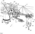
- a lifting crane 1 of the tower crane type, comprises a distributor boom 2 mounted on a tower 3 (also called mast) at the foot 20 of the boom 2.
- a tower 3 also called mast
- the foot 20 of arrow 2 is rotatably mounted on tower 3 along a vertical axis.
- Arrow 2 can be extended to the other side of tower 3 by a counter-jib 30, generally equipped with ballast.
- the lifting crane 1 further comprises a lifting device 4 with double reeving designed to distribute a load (not illustrated) along the boom 2, this lifting device 4 circulating on a raceway formed on the boom 2, between the foot 20 and the tip 21 of the arrow 2, also called the free end of the arrow 2.
- This lifting device 4 comprises a distributor carriage 5 which comprises a suspended structure 50 on the raceway by primary front and rear rolling members formed of rollers or wheels rolling on the raceway.
- This suspended structure 50 supports pulleys which guide a lifting cable 40.
- the suspended structure 50 is connected to a distribution system 55 capable of moving the distributor carriage 5 along the raceway in a forward direction (in other words in the direction of the tip 21 of arrow 2, towards the right in the figures) and a reverse direction (in other words towards the foot 20 of arrow 2, towards the left in the figures).
- this distribution system 55 comprises a motor 56 driving a distribution winch 57 coupled to a distribution cable 58 having strands fixed on either side of the distributor carriage 5 and which circulates up to the tip 21 of the arrow 2.
- the distributor carriage 5 further comprises a main block 51 suspended from the suspended structure 50 by the lifting cable 40.
- This main block 51 supports a lifting member 52 in the lower part; this lifting member 52 being intended for hooking the load and being able to take the form of a hook articulated on the main block 51.
- the lifting device 4 comprises a reeving change system making it possible to reversibly carry out a reeving change between the single reeving configuration and the double reeving configuration, and vice versa.
- This reeving change system includes a remaining carriage 6 which can be moved on the raceway.
- the remaining carriage 6 comprises a frame suspended 60 on the raceway by secondary front and rear rolling members formed of rollers or wheels rolling on the raceway.
- the suspended frame 40 is open at the front, allowing entry/exit of the distributor cart 3.
- This reeving change system further comprises a secondary reeving block 61 supported by the suspended frame 60 of the remaining carriage 6 in double reeving configuration.
- the locking/unlocking mechanism comprises support members integral with the suspended frame 60 of the remaining carriage 6 and on which the secondary block 61 is suspended at a location above the main block in the double block configuration, and the main block 51 comprises the block housing 55 arranged to at least partially accommodate the secondary block 61 in the single block configuration.
- the lifting device 4 is arranged to move from the single reeving configuration to the double reeving configuration, and vice versa, by moving the distributor carriage 5 with its main reeving block 51, and to do this the reeving change system and more specifically its locking/unlocking mechanism are shaped to move from the single hauling configuration to the double hauling configuration, and vice versa, by acting on the distribution system (to move the distributor trolley 5) and on the lifting cable 40.
- the lifting crane 1 comprises a lifting system 45 provided with a motor 46 driving a lifting winch 47 provided with a lifting drum coupled to the lifting cable 40 on which the main block 51 is suspended, and which circulates up to 'at point 21 of arrow 2.
- the lifting crane 1 further comprises an automated reeving determination system 7 designed to automatically determine the reeving configuration between the single reeving configuration and the double reeving configuration.
- This presence detection system 8 may include a first means for detecting the presence/absence of the secondary muffle 61 inside the muffle housing 55 occupied by the secondary muffle 61 in the single muffle configuration.
- This first means can for example comprise a contact sensor, a mechanical sensor, an electrical sensor, an optical sensor, etc. placed for example in front of or inside the muffle housing 55.
- This presence detection system 8 may include a second means for detecting the presence/absence of the secondary muffle 61 at the location above the main muffle 51 occupied by the secondary muffle 61 in the double muffle configuration, and in particular the presence/absence of the secondary block 61 suspended on the support members provided on the remaining carriage 6.
- This second means can for example comprise a contact sensor, a mechanical sensor, an electrical sensor, an optical sensor, etc. placed for example opposite or on the support members.
- This presence detection system 8 may include a third means for detecting the presence/absence of the remaining cart 6 at the storage location (under the foot 20 of the arrow 2 in the illustrated embodiment), to the extent that the presence/absence of the remaining carriage 6 at the storage location is correlated with the location of the secondary block 61 and the blockage configuration.
- the lifting device 4 is in simple reeving configuration, and conversely if the remaining carriage 6 is absent from the storage location then the lifting device 4 is in double reeving configuration.
- This presence detection system 8 may comprise all or part of the first means, the second means and the third means described above.
- the presence detection system 8 comprises the third means, visible on the Figure 3 , which comprises a proximity sensor 80 associated with a stop 81 mounted sliding in translation on a fixed structural element 22 of the lifting crane 1 placed at the level of the foot 20 of the boom 2, so that the stop 81 is located in face of the remaining carriage 6 when the latter is in the storage location, under foot 20 of arrow 2.
- This stop 81 comprises a rod 82 extended by an enlarged head 83.
- the rod 82 is slidably mounted on the structural element 22 and, as such, the rod 82 passes through this structural element 22 in an orifice or bearing.
- the rod 82 has a free front end provided with an abutment surface 84 provided so that the remaining carriage 6 abuts against said abutment surface 84.
- the remaining carriage 6 can present, at the rear, a rear stopper 63 suitable for bearing on the stop surface 84.
- This abutment surface 84 is widened relative to the rod 82, and is in particular in the form of a disc with a diameter greater than the diameter of the rod 82 if the latter is cylindrical.
- the enlarged head 83 has a flat detection surface 85 inclined relative to a sliding direction of the stop 81 on the structural element 22.
- an elastic return member 86 interposed between the structural element 22 and the abutment surface 84, where this return member 86 is in the form of a helical compression spring mounted around the rod 82.
- the proximity sensor 80 is for its part fixedly mounted on the arrow 2 and is arranged facing the detection surface 85 of the enlarged head 83 of the stop 81, where the proximity sensor 80 is configured to detect and measure the distance between said proximity sensor 80 and said detection surface 85.
- This proximity sensor 80 can for example be an inductive sensor or a light sensor (infrared sensor, etc.).
- the stop 81 In the detection position, the stop 81 has slid (backwards), compared to the rest position, which contributes to a modification of the distance between the proximity sensor 80 and the detection surface 85, and also to compression of the return member 86 between the structural element 22 and the abutment surface 84. It should be noted that the detection surface 85 is inclined in the direction of a reduction in the distance between the proximity sensor 80 and the detection surface 85 when the stop 81 has slid (backwards) from its rest position towards the detection position.
- control/command unit 9 makes it possible to automatically determine the hauling configuration based on the detection made by the presence detection system 8.
- the automated reeving determination system 7 comprises a storage module 90 (or memory) connected to the control/command unit 9 to store at least one last reeving configuration determined by the control/command unit 9.
- the last hauling configuration is stored in this storage module 90, so that when a hauling change is made, the control/command unit 9 is configured to automatically determine the reeving configuration also based on this last reeving configuration stored in the storage module.
- the new hauling configuration Once the new hauling configuration has been determined, based at least on the detection made by the presence detection system 8 and the last hauling configuration stored, it is this new hauling configuration which is stored in the module. storage 90 and which therefore becomes the last hauling configuration. In other words, the reeving configuration is updated in the storage module 90 each time the reeving changes.
- the control/command unit 9 can also be connected to an unwinding sensor provided on the lifting winch 47 and capable of measuring an unwound length of the lifting cable 40.
- the control/command unit 9 can compare the unwound lengths of the lifting cable 40 at the start of a first automated sequence and at the start of a second automated sequence which follows or precedes this first automated sequence, and the control/command unit 9 can thus automatically determine the hauling configuration also depending on this comparison between the unwound lengths of the lifting cable 40.
- control/command unit 9 establishes the presence of an error and automatically restarts the current sequence and/or emits an alarm.
- control/command unit 9 confirms that the reeving configuration is the double reeving configuration if no error has been detected, and stores this double reeving configuration in the storage module 90.
- control/command unit 9 confirms that the reeving configuration is the single reeving configuration if no error has been detected, and stores this single reeving configuration in the storage module 90.
- the lifting crane 1 may also include a load sensor 91 coupled to a lifting strand of the lifting cable 90 to measure a lifting tension on this lifting strand.
- control/command unit 9 is connected to this load sensor 91 and is configured to calculate a value of the load as a function of the lifting tension measured on this lifting strand and the determined hauling configuration automatically by the control/command unit 9, to the extent that a single reeving configuration corresponds to a distribution of the load over two lifting strands, and a double reeving configuration corresponds to a distribution of the load over four lifting strands.
- control/command unit 9 can compare the value of the load with a maximum authorized load, and consequently the control/command unit 9 can act on the movement of the distributor cart 5 and the movement of the lifting cable 40 in the event of exceeding the maximum authorized load, and can in particular stop any movement of the load in the event of exceeding the maximum authorized load.
Landscapes
- Engineering & Computer Science (AREA)
- Mechanical Engineering (AREA)
- Structural Engineering (AREA)
- Transportation (AREA)
- Control And Safety Of Cranes (AREA)
- Combined Means For Separation Of Solids (AREA)
- Jib Cranes (AREA)
- Load-Engaging Elements For Cranes (AREA)
Claims (8)
- Hebekran (1), einen Ausleger (2) umfassend und eine Zugvorrichtung (4) mit doppelter Einscherung, die ausgelegt ist, um eine Last entlang des Auslegers (2) zu verteilen und zu heben, wobei die Zugvorrichtung (4) reversibel zwischen zwei Einscherungskonfigurationen konfigurierbar ist, einschließlich einer einfachen Einscherungskonfiguration mit zwei Zugsträngen und einer doppelten Einscherungskonfiguration mit vier Zugsträngen, und wobei die Zugvorrichtung (4) ein Einscherungswechselsystem umfasst, das es ermöglicht, einen Wechsel der Einscherung durchzuführen zwischen der einfachen Einscherungskonfiguration und der doppelten Einscherungskonfiguration, und umgekehrt, wobei der Hebekran (1) ein System der automatisierten Bestimmung der Einscherung (7) umfasst, das ausgelegt ist, um automatisch die Einscherungskonfiguration zwischen der einfachen Einscherungskonfiguration und der doppelten Einscherungskonfiguration zu bestimmen,wobei der Hebekran dadurch gekennzeichnet ist, dass die Zugvorrichtung (4) einen Verteilerwagen (5) umfasst, der eine Struktur (50) umfasst, die am Ausleger (2) aufgehängt ist, und mit einem Verteilersystem (55) verbunden ist, das geeignet ist, den Verteilerwagen (5) entlang des Auslegers (2) in einer Vorwärtsrichtung und einer entgegengesetzten Rückwärtsrichtung zu verschieben, und einen primären Block (51), der an der aufgehängten Struktur (50) durch ein Zugseil (40) aufgehängt ist;und wobei das Einscherungswechselsystem einen sekundären Block (61) umfasst und einen Verriegelungs-/Entriegelungsmechanismus, der mit dem primären Block (51) und dem sekundären Block (61) zusammenwirkt, um von der einfachen Einscherungskonfiguration in die doppelte Einscherungskonfiguration überzugehen oder umgekehrt; unddas System der automatisierten Bestimmung der Einscherung (7) mindestens umfasst:- ein System der Erkennung des Vorhandenseins (8) des sekundären Blocks (61), das geeignet ist, ein Vorhandensein/Nichtvorhandensein des sekundären Blocks (61) an einer vorbestimmten Referenzposition zu erkennen, die vom sekundären Block (61) in der einen oder der anderen Einscherungskonfigurationen eingenommen wird, und- eine Kontroll-/Steuereinheit (9), die an das System der Erkennung des Vorhandenseins (8) des sekundären Blocks (61) angeschlossen ist, und ausgelegt ist, um automatisch die Einscherungskonfiguration zu bestimmen in Abhängigkeit der Erkennung des Vorhandenseins/Nichtvorhandenseins des sekundären Blocks (61) an der Referenzposition;- dadurch, dass das Einscherungswechselsystem die Zugvorrichtung (4) von der einfachen Einscherungskonfiguration in die doppelte Einscherungskonfiguration überführt, und umgekehrt, durch Verschiebung des Verteilerwagens (5) mit seinem primären Block (51), und wobei die Kontroll-Steuereinheit (9) an das Verteilersystem (55) angeschlossen ist, um die Verschiebung des Verteilerwagens (5) zu bedienen, gemäß:- einer ersten automatisierten Sequenz, die die Zugvorrichtung (4) von der einfachen Einscherungskonfiguration in die doppelte Einscherungskonfiguration überführt, und umgekehrt- einer zweiten automatisierten Sequenz, die die Zugvorrichtung (4) von der doppelten Einscherungskonfiguration in die einfache Einscherungskonfiguration überführt;in Abhängigkeit von der Einscherungskonfiguration, die automatisch von der Kontroll-/Steuereinheit (9) bestimmt wurde;dadurch, dass sie eine Zugwinde (47) umfasst, die mit einer Zugtrommel ausgerüstet ist, die mit dem Zugseil (40) zusammenwirkt, um die Last auf und ab zu bewegen, wobei die Zugwinde (47) mit einem Abwicklungssensor ausgestattet ist, der geeignet ist, eine abgewickelte Länge des Zugseils (40) zu messen, wobei die Kontroll-/Steuereinheit (9) ausgelegt ist, um die abgewickelten Längen des Zugseils (40) zu vergleichen, am Beginn einer ersten automatisierten Sequenz und am Beginn einer zweiten automatisierten Sequenz, die der ersten automatisierten Sequenz folgt oder vorausgeht;und dadurch, dass die Kontroll-/Steuereinheit (9) ausgelegt ist, um die Einscherungskonfiguration auch in Abhängigkeit vom Vergleich der abgewickelten Längen des Zugseils (40) am Beginn einer ersten automatisierten Sequenz und am Beginn einer zweiten automatisierten Sequenz, die der ersten automatisierten Sequenz folgt oder vorausgeht, automatisch zu bestimmen.
- Hebekran (1) nach Anspruch 1, wobei das System der automatisierten Bestimmung der Einscherung (7) ein Speichermodul (90) umfasst, das mit der Kontroll-/Steuereinheit (9) verbunden ist, um mindestens eine letzte Einscherungskonfiguration zu speichern, die von der Kontroll-/Steuereinheit (9) bestimmt wurde,
und wobei die Kontroll-/Steuereinheit (9) ausgelegt ist, um die Einscherungskonfiguration auch in Abhängigkeit von der letzten im Speichermodul (90) gespeicherten Einscherungskonfiguration automatisch zu bestimmen. - Hebekran (1) nach einem der Ansprüche 1 und 2, wobei:- in der einfachen Einscherungskonfiguration, der Verriegelungs-/Entriegelungsmechanismus den sekundären Block (61) entriegelt, der innerhalb eines Blockgehäuses (55) positioniert steht, das auf dem primären Block (51) vorgesehenen ist, so dass das Zugseil (40) mit dem primären Block (51) für einen Zug mit zwei Zugsträngen zusammenwirkt, und- in der doppelten Einscherungskonfiguration, der Verriegelungs-/Entriegelungsmechanismus den sekundären Block (61) am Verteilerwagen (5) an einer Position oberhalb des primären Blocks (51) verriegelt, so dass das Zugseil (40) sowohl mit dem primären Block (51) als auch mit dem sekundären Block (61) für einen Zug mit vier Zugsträngen zusammenwirkt.
- Hebekran (1) nach Anspruch 3, wobei das System der Erkennung des Vorhandenseins (8) des sekundären Blocks (61) konfiguriert ist, um das Vorhandensein/Nichtvorhandensein des sekundären Blocks (61) innerhalb des Blockgehäuses (55) zu erkennen, das vom sekundären Block (61) in der einfachen Einscherungskonfiguration ausgefüllt wird und/oder an der Position oberhalb des primären Blocks (51), die vom sekundären Block (61) in der doppelten Einscherungskonfiguration eingenommen wird.
- Hebekran (1) nach einem der Ansprüche 3 und 4, wobei das Einscherungswechselsystem einen Stehwagen (6) umfasst, der ein Gestell (60) umfasst, das am Ausleger (2) aufgehängt ist, und den sekundären Block (61) trägt, wobei:- in der doppelten Einscherungskonfiguration, der Verriegelungs-/Entriegelungsmechanismus den Verteilerwagen (5) und den Stehwagen (6), die vereint und im Verbund entlang des Auslegers (2) verschiebbar sind, zusammen verriegelt, und der sekundäre Block (61) an der Position oberhalb des primären Blocks (51) am Stehwagen (6) aufgehängt ist; und- in der einfachen Einscherungskonfiguration, der Verriegelungs-/Entriegelungsmechanismus den Stehwagen (6) entriegelt, so dass der Verteilerwagen (5) und der Stehwagen (6) getrennt sind, der sekundäre Block (61) innerhalb des Blockgehäuses (55), das am primären Block (51) vorgesehen ist, untergebracht ist, und der Verteilerwagen (5) allein verschiebbar ist, während der Stehwagen (6) mit dem sekundären Block (61) statisch in einer Ruheposition positioniert ist;und das System der Erkennung des Vorhandenseins (8) des sekundären Blocks (61) konfiguriert ist, um ein Vorhandensein/Nichtvorhandensein des Stehwagens (6) an der Ruheposition zu erkennen.
- Hebekran (1) nach einem der Ansprüche 1 bis 5, einen Lastsensor (91) umfassend, der mit einem Zugstrang des Zugseils (40) gekoppelt ist, um eine Zugspannung am Zugstrang zu messen, wobei die Kontroll-/Steuereinheit (9) an den Lastsensor (91) angeschlossen ist und ausgelegt ist, um einen Lastwert in Abhängigkeit von der Zugspannung am Zugstrang und der Einscherungskonfiguration, die von der Kontroll-/Steuereinheit (9) automatisch bestimmt wird, zu berechnen, und zum Beispiel, um den Lastwert mit einer maximal zulässigen Last zu vergleichen.
- Verfahren zum Bedienen eines Hebekrans (1) nach einem der Ansprüche 1 bis 6, die Schritte umfassend:- Durchführen eines Wechsels der Einscherung zwischen der einfachen Einscherungskonfiguration und der doppelten Einscherungskonfiguration oder umgekehrt;- Erkennen eines Vorhandenseins/Nichtvorhandenseins des sekundären Blocks (61) an einer vorbestimmten Referenzposition, die vom sekundären Block (61) in der einen oder der anderen Einscherungskonfigurationen eingenommen wird;- automatisches Bestimmen der Einscherungskonfiguration zwischen der einfachen Einscherungskonfiguration und der doppelten Einscherungskonfiguration in Abhängigkeit von der Erkennung des Vorhandenseins/Nichtvorhandenseins des sekundären Blocks (61) an der Referenzposition; wobei das Bedienungsverfahren einen Bedienungsschritt der Verschiebung des Verteilerwagens (5) umfasst, gemäß:- einer ersten automatisierten Sequenz, die die Zugvorrichtung (4) von der einfachen Einscherungskonfiguration in die doppelte Einscherungskonfiguration überführt, und umgekehrt- einer zweiten automatisierten Sequenz, die die Zugvorrichtung (4) von der doppelten Einscherungskonfiguration in die einfache Einscherungskonfiguration überführt;in Abhängigkeit von der Einscherungskonfiguration, die automatisch bestimmt wurde; undwobei das Bedienungsverfahren die Schritte umfasst:- Messen einer abgewickelten Länge des Zugseils (40), wobei das Zugseil (40) mit einer Zugtrommel einer Zugwinde (47) zusammenwirkt, um die Last auf und ab zu bewegen,- Vergleichen der abgewickelten Längen des Zugseils (40) am Beginn einer ersten automatisierten Sequenz und am Beginn einer zweiten automatisierten Sequenz, die der ersten automatisierten Sequenz folgt oder vorausgeht;und wobei die Konfiguration der Zugvorrichtung (4) auch in Abhängigkeit des Vergleichs zwischen den abgewickelten Längen des Zugseils (40) am Beginn einer ersten automatisierten Sequenz und am Beginn einer zweiten automatisierten Sequenz, die der ersten automatisierten Sequenz folgt oder vorausgeht, automatisch bestimmt wird.
- Bedienungsverfahren nach Anspruch 7, die Schritte umfassend:- Messen einer Zugspannung an einem Strang des Zugseils (40);- Berechnen eines Lastwerts in Abhängigkeit von der Zugspannung am Strang des Zugseils (40) und der Einscherungskonfiguration, die automatisch erkannt wurde, und zum Beispiel, Vergleichen des Lastwerts mit einer maximal zulässigen Last.
Applications Claiming Priority (1)
| Application Number | Priority Date | Filing Date | Title |
|---|---|---|---|
| FR1913446A FR3103803B1 (fr) | 2019-11-29 | 2019-11-29 | Grue de levage avec système de détermination automatisée du mouflage |
Publications (2)
| Publication Number | Publication Date |
|---|---|
| EP3828124A1 EP3828124A1 (de) | 2021-06-02 |
| EP3828124B1 true EP3828124B1 (de) | 2024-04-24 |
Family
ID=69468910
Family Applications (1)
| Application Number | Title | Priority Date | Filing Date |
|---|---|---|---|
| EP20209155.9A Active EP3828124B1 (de) | 2019-11-29 | 2020-11-23 | Hebekran mit automatischem bestimmungssystem der einscherung |
Country Status (4)
| Country | Link |
|---|---|
| US (1) | US11753284B2 (de) |
| EP (1) | EP3828124B1 (de) |
| ES (1) | ES2982697T3 (de) |
| FR (1) | FR3103803B1 (de) |
Families Citing this family (2)
| Publication number | Priority date | Publication date | Assignee | Title |
|---|---|---|---|---|
| FR3137908B1 (fr) * | 2022-07-12 | 2025-01-10 | Manitowoc Crane Group France | Procédé automatique pour la détermination lors d’un levage d’une position physique de fin de course d’un moufle d’une grue à tour |
| FR3139561B1 (fr) * | 2022-09-14 | 2024-12-20 | Manitowoc Crane Group France | Engin de levage avec changement de mouflage automatisé |
Family Cites Families (8)
| Publication number | Priority date | Publication date | Assignee | Title |
|---|---|---|---|---|
| US2463394A (en) * | 1945-10-17 | 1949-03-01 | Carl B King | Hoist |
| SU397470A1 (ru) * | 1969-02-06 | 1973-09-17 | Грузовой полиспаст переменной кратности для стреловых кранов | |
| DE2116544A1 (de) * | 1971-04-05 | 1972-11-23 | F.B. Kroell A/S, Roedovre (Dänemark) | Umschervorrichtung für Windwerke mit einer mehrsträngig aufgehängten Unterflasche |
| US3993287A (en) * | 1973-02-09 | 1976-11-23 | Linden-Alimak Ab | Method and device of reblocking to an increased or reduced number of rope parts at a hoisting gear |
| US6926103B1 (en) * | 2001-07-02 | 2005-08-09 | Itrec B.V. | Splittable block on a derrick |
| FR3061164B1 (fr) | 2016-12-23 | 2019-05-24 | Manitowoc Crane Group France | Grue de levage comprenant un dispositif de levage a double mouflage |
| FR3061163B1 (fr) | 2016-12-23 | 2019-05-24 | Manitowoc Crane Group France | Grue de levage comprenant un dispositif de levage a double mouflage |
| CN109879181B (zh) * | 2019-03-13 | 2024-02-13 | 科曼萨建设机械(杭州)有限公司 | 动臂塔机的自动换倍率转换装置及其使用方法 |
-
2019
- 2019-11-29 FR FR1913446A patent/FR3103803B1/fr not_active Expired - Fee Related
-
2020
- 2020-11-23 EP EP20209155.9A patent/EP3828124B1/de active Active
- 2020-11-23 ES ES20209155T patent/ES2982697T3/es active Active
- 2020-11-25 US US17/104,643 patent/US11753284B2/en active Active
Also Published As
| Publication number | Publication date |
|---|---|
| EP3828124A1 (de) | 2021-06-02 |
| ES2982697T3 (es) | 2024-10-17 |
| US11753284B2 (en) | 2023-09-12 |
| US20210188599A1 (en) | 2021-06-24 |
| FR3103803B1 (fr) | 2022-02-11 |
| FR3103803A1 (fr) | 2021-06-04 |
Similar Documents
| Publication | Publication Date | Title |
|---|---|---|
| EP3828124B1 (de) | Hebekran mit automatischem bestimmungssystem der einscherung | |
| FR2503415A1 (fr) | Dispositif de commande pour un mecanisme de chargement et de dechargement, notamment d'un chariot elevateur a fourche | |
| EP2167251B1 (de) | Vorrichtung zur handhabung einer last, z. b. einer blechspule | |
| EP3466862B1 (de) | Kran mit hochklappbarem ausleger mit verriegelungsvorrichtung des auslegers in hochgeklappter konfiguration | |
| EP3791844B1 (de) | System zur automatisierung des beladens und herausziehens eines wagens an einer aufnahmehalterung | |
| EP3418245A1 (de) | Vorrichtung zur handhabung eines gegenstands | |
| EP4049960B1 (de) | Hubvorrichtung mit doppelter einscherung und drehverriegelungsmechanismus mit schnappschloss | |
| FR2692528A1 (fr) | Dispositif de captation d'électricité pour un véhicule tel qu'un trolleybus ou un tramway. | |
| EP3415458B1 (de) | Gerät und verfahren zur automatischen spannung eines verteilerkabels eines kranes | |
| FR2949627A1 (fr) | Procede pour verifier l'etat d'un frein d'un mecanisme commande par un convertisseur de frequence ou autre controleur | |
| EP2035310B1 (de) | Spuler mit expandierbarem dorn für eine rolle | |
| EP1710197B1 (de) | Sicherheitsvorrichtung für Laufkatze eines Krans | |
| EP0340076B1 (de) | Vorrichtung zum Halten und Laden von länglichen Gegenständen, insbesondere Leitern auf dem Dach eines Fahrzeuges | |
| FR3022230A1 (fr) | Systeme declencheur d'un dispositif de blocage de cabine d'ascenseur, notamment limiteur de vitesse. | |
| WO2018065385A1 (fr) | Chaumard a ouverture automatique et dispositif de remorquage comprenant le chaumard | |
| EP4345052B1 (de) | Hebezeug mit automatisierter änderung der schlichtkonfiguration | |
| EP2133261A1 (de) | Vorrichtung zum Aufrollen und Durchspannen eines flatternden Vordersegels (Fock) oder eines freien Vorlieks für Segelboot | |
| EP3924070B1 (de) | Verbinder, lösbare gabelattrappe mit einem solchen verbinder und betriebsverfahren | |
| EP4273085B1 (de) | Doppelblasheber mit verbessertem verriegelungsmechanismus | |
| FR2678596A1 (fr) | Dispositif de prehension pour le levage ou la manutention de pieces. | |
| FR2939398A1 (fr) | Dispositif pour securiser la manutention d'une charge roulante sur une plate-forme telle que le pont d'un navire soumis a une mer agitee. | |
| WO2025176577A1 (fr) | Systeme et procede de levage de colis | |
| EP3265626A1 (de) | Plattform und verfahren zur veränderung der position von mindestens einem hubbalken solch einer plattform | |
| FR2678576A1 (fr) | Systeme de bloqueurs interdependants pour palans de chariot d'ecoute de grand-voile et analogues. | |
| FR2647584A1 (fr) | Dispositif de levage auxiliaire pour reacteur nucleaire |
Legal Events
| Date | Code | Title | Description |
|---|---|---|---|
| PUAI | Public reference made under article 153(3) epc to a published international application that has entered the european phase |
Free format text: ORIGINAL CODE: 0009012 |
|
| STAA | Information on the status of an ep patent application or granted ep patent |
Free format text: STATUS: THE APPLICATION HAS BEEN PUBLISHED |
|
| AK | Designated contracting states |
Kind code of ref document: A1 Designated state(s): AL AT BE BG CH CY CZ DE DK EE ES FI FR GB GR HR HU IE IS IT LI LT LU LV MC MK MT NL NO PL PT RO RS SE SI SK SM TR |
|
| STAA | Information on the status of an ep patent application or granted ep patent |
Free format text: STATUS: REQUEST FOR EXAMINATION WAS MADE |
|
| 17P | Request for examination filed |
Effective date: 20211117 |
|
| RBV | Designated contracting states (corrected) |
Designated state(s): AL AT BE BG CH CY CZ DE DK EE ES FI FR GB GR HR HU IE IS IT LI LT LU LV MC MK MT NL NO PL PT RO RS SE SI SK SM TR |
|
| GRAP | Despatch of communication of intention to grant a patent |
Free format text: ORIGINAL CODE: EPIDOSNIGR1 |
|
| STAA | Information on the status of an ep patent application or granted ep patent |
Free format text: STATUS: GRANT OF PATENT IS INTENDED |
|
| RIC1 | Information provided on ipc code assigned before grant |
Ipc: B66C 23/26 20060101ALI20231027BHEP Ipc: B66C 23/90 20060101ALI20231027BHEP Ipc: B66D 3/04 20060101AFI20231027BHEP |
|
| INTG | Intention to grant announced |
Effective date: 20231116 |
|
| GRAS | Grant fee paid |
Free format text: ORIGINAL CODE: EPIDOSNIGR3 |
|
| GRAA | (expected) grant |
Free format text: ORIGINAL CODE: 0009210 |
|
| STAA | Information on the status of an ep patent application or granted ep patent |
Free format text: STATUS: THE PATENT HAS BEEN GRANTED |
|
| AK | Designated contracting states |
Kind code of ref document: B1 Designated state(s): AL AT BE BG CH CY CZ DE DK EE ES FI FR GB GR HR HU IE IS IT LI LT LU LV MC MK MT NL NO PL PT RO RS SE SI SK SM TR |
|
| REG | Reference to a national code |
Ref country code: GB Ref legal event code: FG4D Free format text: NOT ENGLISH |
|
| REG | Reference to a national code |
Ref country code: CH Ref legal event code: EP |
|
| REG | Reference to a national code |
Ref country code: DE Ref legal event code: R096 Ref document number: 602020029465 Country of ref document: DE |
|
| REG | Reference to a national code |
Ref country code: IE Ref legal event code: FG4D Free format text: LANGUAGE OF EP DOCUMENT: FRENCH |
|
| REG | Reference to a national code |
Ref country code: LT Ref legal event code: MG9D |
|
| REG | Reference to a national code |
Ref country code: NL Ref legal event code: MP Effective date: 20240424 |
|
| REG | Reference to a national code |
Ref country code: AT Ref legal event code: MK05 Ref document number: 1679431 Country of ref document: AT Kind code of ref document: T Effective date: 20240424 |
|
| PG25 | Lapsed in a contracting state [announced via postgrant information from national office to epo] |
Ref country code: NL Free format text: LAPSE BECAUSE OF FAILURE TO SUBMIT A TRANSLATION OF THE DESCRIPTION OR TO PAY THE FEE WITHIN THE PRESCRIBED TIME-LIMIT Effective date: 20240424 |
|
| PG25 | Lapsed in a contracting state [announced via postgrant information from national office to epo] |
Ref country code: NL Free format text: LAPSE BECAUSE OF FAILURE TO SUBMIT A TRANSLATION OF THE DESCRIPTION OR TO PAY THE FEE WITHIN THE PRESCRIBED TIME-LIMIT Effective date: 20240424 |
|
| PG25 | Lapsed in a contracting state [announced via postgrant information from national office to epo] |
Ref country code: IS Free format text: LAPSE BECAUSE OF FAILURE TO SUBMIT A TRANSLATION OF THE DESCRIPTION OR TO PAY THE FEE WITHIN THE PRESCRIBED TIME-LIMIT Effective date: 20240824 |
|
| PG25 | Lapsed in a contracting state [announced via postgrant information from national office to epo] |
Ref country code: BG Free format text: LAPSE BECAUSE OF FAILURE TO SUBMIT A TRANSLATION OF THE DESCRIPTION OR TO PAY THE FEE WITHIN THE PRESCRIBED TIME-LIMIT Effective date: 20240424 |
|
| PG25 | Lapsed in a contracting state [announced via postgrant information from national office to epo] |
Ref country code: HR Free format text: LAPSE BECAUSE OF FAILURE TO SUBMIT A TRANSLATION OF THE DESCRIPTION OR TO PAY THE FEE WITHIN THE PRESCRIBED TIME-LIMIT Effective date: 20240424 Ref country code: FI Free format text: LAPSE BECAUSE OF FAILURE TO SUBMIT A TRANSLATION OF THE DESCRIPTION OR TO PAY THE FEE WITHIN THE PRESCRIBED TIME-LIMIT Effective date: 20240424 |
|
| PG25 | Lapsed in a contracting state [announced via postgrant information from national office to epo] |
Ref country code: GR Free format text: LAPSE BECAUSE OF FAILURE TO SUBMIT A TRANSLATION OF THE DESCRIPTION OR TO PAY THE FEE WITHIN THE PRESCRIBED TIME-LIMIT Effective date: 20240725 |
|
| PG25 | Lapsed in a contracting state [announced via postgrant information from national office to epo] |
Ref country code: PT Free format text: LAPSE BECAUSE OF FAILURE TO SUBMIT A TRANSLATION OF THE DESCRIPTION OR TO PAY THE FEE WITHIN THE PRESCRIBED TIME-LIMIT Effective date: 20240826 |
|
| REG | Reference to a national code |
Ref country code: ES Ref legal event code: FG2A Ref document number: 2982697 Country of ref document: ES Kind code of ref document: T3 Effective date: 20241017 |
|
| PG25 | Lapsed in a contracting state [announced via postgrant information from national office to epo] |
Ref country code: AT Free format text: LAPSE BECAUSE OF FAILURE TO SUBMIT A TRANSLATION OF THE DESCRIPTION OR TO PAY THE FEE WITHIN THE PRESCRIBED TIME-LIMIT Effective date: 20240424 |
|
| PG25 | Lapsed in a contracting state [announced via postgrant information from national office to epo] |
Ref country code: PL Free format text: LAPSE BECAUSE OF FAILURE TO SUBMIT A TRANSLATION OF THE DESCRIPTION OR TO PAY THE FEE WITHIN THE PRESCRIBED TIME-LIMIT Effective date: 20240424 |
|
| PG25 | Lapsed in a contracting state [announced via postgrant information from national office to epo] |
Ref country code: LV Free format text: LAPSE BECAUSE OF FAILURE TO SUBMIT A TRANSLATION OF THE DESCRIPTION OR TO PAY THE FEE WITHIN THE PRESCRIBED TIME-LIMIT Effective date: 20240424 |
|
| PG25 | Lapsed in a contracting state [announced via postgrant information from national office to epo] |
Ref country code: PT Free format text: LAPSE BECAUSE OF FAILURE TO SUBMIT A TRANSLATION OF THE DESCRIPTION OR TO PAY THE FEE WITHIN THE PRESCRIBED TIME-LIMIT Effective date: 20240826 Ref country code: PL Free format text: LAPSE BECAUSE OF FAILURE TO SUBMIT A TRANSLATION OF THE DESCRIPTION OR TO PAY THE FEE WITHIN THE PRESCRIBED TIME-LIMIT Effective date: 20240424 Ref country code: NO Free format text: LAPSE BECAUSE OF FAILURE TO SUBMIT A TRANSLATION OF THE DESCRIPTION OR TO PAY THE FEE WITHIN THE PRESCRIBED TIME-LIMIT Effective date: 20240724 Ref country code: LV Free format text: LAPSE BECAUSE OF FAILURE TO SUBMIT A TRANSLATION OF THE DESCRIPTION OR TO PAY THE FEE WITHIN THE PRESCRIBED TIME-LIMIT Effective date: 20240424 Ref country code: IS Free format text: LAPSE BECAUSE OF FAILURE TO SUBMIT A TRANSLATION OF THE DESCRIPTION OR TO PAY THE FEE WITHIN THE PRESCRIBED TIME-LIMIT Effective date: 20240824 Ref country code: HR Free format text: LAPSE BECAUSE OF FAILURE TO SUBMIT A TRANSLATION OF THE DESCRIPTION OR TO PAY THE FEE WITHIN THE PRESCRIBED TIME-LIMIT Effective date: 20240424 Ref country code: GR Free format text: LAPSE BECAUSE OF FAILURE TO SUBMIT A TRANSLATION OF THE DESCRIPTION OR TO PAY THE FEE WITHIN THE PRESCRIBED TIME-LIMIT Effective date: 20240725 Ref country code: FI Free format text: LAPSE BECAUSE OF FAILURE TO SUBMIT A TRANSLATION OF THE DESCRIPTION OR TO PAY THE FEE WITHIN THE PRESCRIBED TIME-LIMIT Effective date: 20240424 Ref country code: BG Free format text: LAPSE BECAUSE OF FAILURE TO SUBMIT A TRANSLATION OF THE DESCRIPTION OR TO PAY THE FEE WITHIN THE PRESCRIBED TIME-LIMIT Effective date: 20240424 Ref country code: AT Free format text: LAPSE BECAUSE OF FAILURE TO SUBMIT A TRANSLATION OF THE DESCRIPTION OR TO PAY THE FEE WITHIN THE PRESCRIBED TIME-LIMIT Effective date: 20240424 Ref country code: RS Free format text: LAPSE BECAUSE OF FAILURE TO SUBMIT A TRANSLATION OF THE DESCRIPTION OR TO PAY THE FEE WITHIN THE PRESCRIBED TIME-LIMIT Effective date: 20240724 |
|
| PG25 | Lapsed in a contracting state [announced via postgrant information from national office to epo] |
Ref country code: DK Free format text: LAPSE BECAUSE OF FAILURE TO SUBMIT A TRANSLATION OF THE DESCRIPTION OR TO PAY THE FEE WITHIN THE PRESCRIBED TIME-LIMIT Effective date: 20240424 |
|
| PG25 | Lapsed in a contracting state [announced via postgrant information from national office to epo] |
Ref country code: EE Free format text: LAPSE BECAUSE OF FAILURE TO SUBMIT A TRANSLATION OF THE DESCRIPTION OR TO PAY THE FEE WITHIN THE PRESCRIBED TIME-LIMIT Effective date: 20240424 |
|
| PG25 | Lapsed in a contracting state [announced via postgrant information from national office to epo] |
Ref country code: CZ Free format text: LAPSE BECAUSE OF FAILURE TO SUBMIT A TRANSLATION OF THE DESCRIPTION OR TO PAY THE FEE WITHIN THE PRESCRIBED TIME-LIMIT Effective date: 20240424 |
|
| PG25 | Lapsed in a contracting state [announced via postgrant information from national office to epo] |
Ref country code: SK Free format text: LAPSE BECAUSE OF FAILURE TO SUBMIT A TRANSLATION OF THE DESCRIPTION OR TO PAY THE FEE WITHIN THE PRESCRIBED TIME-LIMIT Effective date: 20240424 Ref country code: RO Free format text: LAPSE BECAUSE OF FAILURE TO SUBMIT A TRANSLATION OF THE DESCRIPTION OR TO PAY THE FEE WITHIN THE PRESCRIBED TIME-LIMIT Effective date: 20240424 |
|
| REG | Reference to a national code |
Ref country code: DE Ref legal event code: R097 Ref document number: 602020029465 Country of ref document: DE |
|
| PG25 | Lapsed in a contracting state [announced via postgrant information from national office to epo] |
Ref country code: SM Free format text: LAPSE BECAUSE OF FAILURE TO SUBMIT A TRANSLATION OF THE DESCRIPTION OR TO PAY THE FEE WITHIN THE PRESCRIBED TIME-LIMIT Effective date: 20240424 |
|
| PG25 | Lapsed in a contracting state [announced via postgrant information from national office to epo] |
Ref country code: SM Free format text: LAPSE BECAUSE OF FAILURE TO SUBMIT A TRANSLATION OF THE DESCRIPTION OR TO PAY THE FEE WITHIN THE PRESCRIBED TIME-LIMIT Effective date: 20240424 Ref country code: SK Free format text: LAPSE BECAUSE OF FAILURE TO SUBMIT A TRANSLATION OF THE DESCRIPTION OR TO PAY THE FEE WITHIN THE PRESCRIBED TIME-LIMIT Effective date: 20240424 Ref country code: RO Free format text: LAPSE BECAUSE OF FAILURE TO SUBMIT A TRANSLATION OF THE DESCRIPTION OR TO PAY THE FEE WITHIN THE PRESCRIBED TIME-LIMIT Effective date: 20240424 Ref country code: EE Free format text: LAPSE BECAUSE OF FAILURE TO SUBMIT A TRANSLATION OF THE DESCRIPTION OR TO PAY THE FEE WITHIN THE PRESCRIBED TIME-LIMIT Effective date: 20240424 Ref country code: DK Free format text: LAPSE BECAUSE OF FAILURE TO SUBMIT A TRANSLATION OF THE DESCRIPTION OR TO PAY THE FEE WITHIN THE PRESCRIBED TIME-LIMIT Effective date: 20240424 Ref country code: CZ Free format text: LAPSE BECAUSE OF FAILURE TO SUBMIT A TRANSLATION OF THE DESCRIPTION OR TO PAY THE FEE WITHIN THE PRESCRIBED TIME-LIMIT Effective date: 20240424 |
|
| PLBE | No opposition filed within time limit |
Free format text: ORIGINAL CODE: 0009261 |
|
| STAA | Information on the status of an ep patent application or granted ep patent |
Free format text: STATUS: NO OPPOSITION FILED WITHIN TIME LIMIT |
|
| 26N | No opposition filed |
Effective date: 20250127 |
|
| PG25 | Lapsed in a contracting state [announced via postgrant information from national office to epo] |
Ref country code: SI Free format text: LAPSE BECAUSE OF FAILURE TO SUBMIT A TRANSLATION OF THE DESCRIPTION OR TO PAY THE FEE WITHIN THE PRESCRIBED TIME-LIMIT Effective date: 20240424 |
|
| REG | Reference to a national code |
Ref country code: CH Ref legal event code: PL |
|
| PG25 | Lapsed in a contracting state [announced via postgrant information from national office to epo] |
Ref country code: MC Free format text: LAPSE BECAUSE OF FAILURE TO SUBMIT A TRANSLATION OF THE DESCRIPTION OR TO PAY THE FEE WITHIN THE PRESCRIBED TIME-LIMIT Effective date: 20240424 |
|
| PG25 | Lapsed in a contracting state [announced via postgrant information from national office to epo] |
Ref country code: LU Free format text: LAPSE BECAUSE OF NON-PAYMENT OF DUE FEES Effective date: 20241123 |
|
| REG | Reference to a national code |
Ref country code: CH Ref legal event code: PL |
|
| GBPC | Gb: european patent ceased through non-payment of renewal fee |
Effective date: 20241123 |
|
| PG25 | Lapsed in a contracting state [announced via postgrant information from national office to epo] |
Ref country code: CH Free format text: LAPSE BECAUSE OF NON-PAYMENT OF DUE FEES Effective date: 20241130 |
|
| REG | Reference to a national code |
Ref country code: BE Ref legal event code: MM Effective date: 20241130 |
|
| PG25 | Lapsed in a contracting state [announced via postgrant information from national office to epo] |
Ref country code: SE Free format text: LAPSE BECAUSE OF FAILURE TO SUBMIT A TRANSLATION OF THE DESCRIPTION OR TO PAY THE FEE WITHIN THE PRESCRIBED TIME-LIMIT Effective date: 20240424 |
|
| PG25 | Lapsed in a contracting state [announced via postgrant information from national office to epo] |
Ref country code: GB Free format text: LAPSE BECAUSE OF NON-PAYMENT OF DUE FEES Effective date: 20241123 Ref country code: BE Free format text: LAPSE BECAUSE OF NON-PAYMENT OF DUE FEES Effective date: 20241130 |
|
| PG25 | Lapsed in a contracting state [announced via postgrant information from national office to epo] |
Ref country code: IE Free format text: LAPSE BECAUSE OF NON-PAYMENT OF DUE FEES Effective date: 20241123 |
|
| PGFP | Annual fee paid to national office [announced via postgrant information from national office to epo] |
Ref country code: DE Payment date: 20251119 Year of fee payment: 6 |
|
| PG25 | Lapsed in a contracting state [announced via postgrant information from national office to epo] |
Ref country code: IT Free format text: LAPSE BECAUSE OF NON-PAYMENT OF DUE FEES Effective date: 20241123 |
|
| PGFP | Annual fee paid to national office [announced via postgrant information from national office to epo] |
Ref country code: FR Payment date: 20251126 Year of fee payment: 6 |
|
| PGFP | Annual fee paid to national office [announced via postgrant information from national office to epo] |
Ref country code: ES Payment date: 20251229 Year of fee payment: 6 |