EP3828011B1 - Reifenlauffläche - Google Patents
Reifenlauffläche Download PDFInfo
- Publication number
- EP3828011B1 EP3828011B1 EP21152672.8A EP21152672A EP3828011B1 EP 3828011 B1 EP3828011 B1 EP 3828011B1 EP 21152672 A EP21152672 A EP 21152672A EP 3828011 B1 EP3828011 B1 EP 3828011B1
- Authority
- EP
- European Patent Office
- Prior art keywords
- crown
- tyre
- groove
- main
- lateral grooves
- Prior art date
- Legal status (The legal status is an assumption and is not a legal conclusion. Google has not performed a legal analysis and makes no representation as to the accuracy of the status listed.)
- Active
Links
- 238000012360 testing method Methods 0.000 description 9
- 230000000052 comparative effect Effects 0.000 description 7
- 238000010008 shearing Methods 0.000 description 4
- 230000007423 decrease Effects 0.000 description 3
- 230000001133 acceleration Effects 0.000 description 2
- 238000011161 development Methods 0.000 description 2
- 238000006243 chemical reaction Methods 0.000 description 1
- 230000003247 decreasing effect Effects 0.000 description 1
- 238000013461 design Methods 0.000 description 1
- 238000006073 displacement reaction Methods 0.000 description 1
- 230000000694 effects Effects 0.000 description 1
- 238000011056 performance test Methods 0.000 description 1
- 238000010998 test method Methods 0.000 description 1
Images


Classifications
-
- B—PERFORMING OPERATIONS; TRANSPORTING
- B60—VEHICLES IN GENERAL
- B60C—VEHICLE TYRES; TYRE INFLATION; TYRE CHANGING; CONNECTING VALVES TO INFLATABLE ELASTIC BODIES IN GENERAL; DEVICES OR ARRANGEMENTS RELATED TO TYRES
- B60C11/00—Tyre tread bands; Tread patterns; Anti-skid inserts
- B60C11/03—Tread patterns
- B60C11/12—Tread patterns characterised by the use of narrow slits or incisions, e.g. sipes
-
- B—PERFORMING OPERATIONS; TRANSPORTING
- B60—VEHICLES IN GENERAL
- B60C—VEHICLE TYRES; TYRE INFLATION; TYRE CHANGING; CONNECTING VALVES TO INFLATABLE ELASTIC BODIES IN GENERAL; DEVICES OR ARRANGEMENTS RELATED TO TYRES
- B60C11/00—Tyre tread bands; Tread patterns; Anti-skid inserts
- B60C11/03—Tread patterns
- B60C11/0306—Patterns comprising block rows or discontinuous ribs
- B60C11/0309—Patterns comprising block rows or discontinuous ribs further characterised by the groove cross-section
-
- B—PERFORMING OPERATIONS; TRANSPORTING
- B60—VEHICLES IN GENERAL
- B60C—VEHICLE TYRES; TYRE INFLATION; TYRE CHANGING; CONNECTING VALVES TO INFLATABLE ELASTIC BODIES IN GENERAL; DEVICES OR ARRANGEMENTS RELATED TO TYRES
- B60C11/00—Tyre tread bands; Tread patterns; Anti-skid inserts
- B60C11/03—Tread patterns
- B60C11/0304—Asymmetric patterns
-
- B—PERFORMING OPERATIONS; TRANSPORTING
- B60—VEHICLES IN GENERAL
- B60C—VEHICLE TYRES; TYRE INFLATION; TYRE CHANGING; CONNECTING VALVES TO INFLATABLE ELASTIC BODIES IN GENERAL; DEVICES OR ARRANGEMENTS RELATED TO TYRES
- B60C11/00—Tyre tread bands; Tread patterns; Anti-skid inserts
- B60C11/03—Tread patterns
- B60C11/0306—Patterns comprising block rows or discontinuous ribs
-
- B—PERFORMING OPERATIONS; TRANSPORTING
- B60—VEHICLES IN GENERAL
- B60C—VEHICLE TYRES; TYRE INFLATION; TYRE CHANGING; CONNECTING VALVES TO INFLATABLE ELASTIC BODIES IN GENERAL; DEVICES OR ARRANGEMENTS RELATED TO TYRES
- B60C11/00—Tyre tread bands; Tread patterns; Anti-skid inserts
- B60C11/03—Tread patterns
- B60C11/12—Tread patterns characterised by the use of narrow slits or incisions, e.g. sipes
- B60C11/1272—Width of the sipe
- B60C11/1281—Width of the sipe different within the same sipe, i.e. enlarged width portion at sipe bottom or along its length
-
- B—PERFORMING OPERATIONS; TRANSPORTING
- B60—VEHICLES IN GENERAL
- B60C—VEHICLE TYRES; TYRE INFLATION; TYRE CHANGING; CONNECTING VALVES TO INFLATABLE ELASTIC BODIES IN GENERAL; DEVICES OR ARRANGEMENTS RELATED TO TYRES
- B60C11/00—Tyre tread bands; Tread patterns; Anti-skid inserts
- B60C11/03—Tread patterns
- B60C11/13—Tread patterns characterised by the groove cross-section, e.g. for buttressing or preventing stone-trapping
-
- B—PERFORMING OPERATIONS; TRANSPORTING
- B60—VEHICLES IN GENERAL
- B60C—VEHICLE TYRES; TYRE INFLATION; TYRE CHANGING; CONNECTING VALVES TO INFLATABLE ELASTIC BODIES IN GENERAL; DEVICES OR ARRANGEMENTS RELATED TO TYRES
- B60C11/00—Tyre tread bands; Tread patterns; Anti-skid inserts
- B60C11/03—Tread patterns
- B60C2011/0337—Tread patterns characterised by particular design features of the pattern
- B60C2011/0339—Grooves
- B60C2011/0341—Circumferential grooves
- B60C2011/0346—Circumferential grooves with zigzag shape
-
- B—PERFORMING OPERATIONS; TRANSPORTING
- B60—VEHICLES IN GENERAL
- B60C—VEHICLE TYRES; TYRE INFLATION; TYRE CHANGING; CONNECTING VALVES TO INFLATABLE ELASTIC BODIES IN GENERAL; DEVICES OR ARRANGEMENTS RELATED TO TYRES
- B60C11/00—Tyre tread bands; Tread patterns; Anti-skid inserts
- B60C11/03—Tread patterns
- B60C2011/0337—Tread patterns characterised by particular design features of the pattern
- B60C2011/0339—Grooves
- B60C2011/0358—Lateral grooves, i.e. having an angle of 45 to 90 degees to the equatorial plane
- B60C2011/0365—Lateral grooves, i.e. having an angle of 45 to 90 degees to the equatorial plane characterised by width
-
- B—PERFORMING OPERATIONS; TRANSPORTING
- B60—VEHICLES IN GENERAL
- B60C—VEHICLE TYRES; TYRE INFLATION; TYRE CHANGING; CONNECTING VALVES TO INFLATABLE ELASTIC BODIES IN GENERAL; DEVICES OR ARRANGEMENTS RELATED TO TYRES
- B60C11/00—Tyre tread bands; Tread patterns; Anti-skid inserts
- B60C11/03—Tread patterns
- B60C11/13—Tread patterns characterised by the groove cross-section, e.g. for buttressing or preventing stone-trapping
- B60C11/1307—Tread patterns characterised by the groove cross-section, e.g. for buttressing or preventing stone-trapping with special features of the groove walls
- B60C2011/1338—Tread patterns characterised by the groove cross-section, e.g. for buttressing or preventing stone-trapping with special features of the groove walls comprising protrusions
-
- B—PERFORMING OPERATIONS; TRANSPORTING
- B60—VEHICLES IN GENERAL
- B60C—VEHICLE TYRES; TYRE INFLATION; TYRE CHANGING; CONNECTING VALVES TO INFLATABLE ELASTIC BODIES IN GENERAL; DEVICES OR ARRANGEMENTS RELATED TO TYRES
- B60C2200/00—Tyres specially adapted for particular applications
- B60C2200/04—Tyres specially adapted for particular applications for road vehicles, e.g. passenger cars
-
- Y—GENERAL TAGGING OF NEW TECHNOLOGICAL DEVELOPMENTS; GENERAL TAGGING OF CROSS-SECTIONAL TECHNOLOGIES SPANNING OVER SEVERAL SECTIONS OF THE IPC; TECHNICAL SUBJECTS COVERED BY FORMER USPC CROSS-REFERENCE ART COLLECTIONS [XRACs] AND DIGESTS
- Y02—TECHNOLOGIES OR APPLICATIONS FOR MITIGATION OR ADAPTATION AGAINST CLIMATE CHANGE
- Y02T—CLIMATE CHANGE MITIGATION TECHNOLOGIES RELATED TO TRANSPORTATION
- Y02T10/00—Road transport of goods or passengers
- Y02T10/80—Technologies aiming to reduce greenhouse gasses emissions common to all road transportation technologies
- Y02T10/86—Optimisation of rolling resistance, e.g. weight reduction
Definitions
- the present invention relates to tyres suitable for driving on snow.
- JP 2018-001976 A discloses a pneumatic tyre which is suitable for driving on snow.
- the pneumatic tyre includes a tread portion provided with crown lateral grooves with groove bottom sipes which are opened at the groove bottoms.
- the groove bottom sipes can prevent the crown lateral grooves from being stuffed with snow.
- EP 3 342 605 A1 discloses a tyre according to the preamble of claim 1.
- the present invention has been made in view of the above circumstances and has a major object to provide a tyre capable of improving on-snow performance while preventing reduction in wear resistance.
- a tyre includes a tread portion including at least one crown land portion defined between two main grooves extending continuously in a tyre circumferential direction, the at least one crown land portion being provided with crown lateral grooves traversing the at least one crown land portion, each of the crown lateral grooves, in a cross-sectional view perpendicular to its longitudinal direction, including a sipe portion having a width equal to or less than 1.5 mm, and a main portion connected to the sipe portion and opening at a ground contact surface of the at least one crown land portion, wherein the main portion has a width enlarging from the sipe portion, the main portion has a depth smaller than depths of the main grooves, and the sipe portion has a first wall extending in a tyre radial direction so as to be continuous with a first wall of the main portion to form a single groove wall together.
- the main grooves include a crown main groove located on a same side with respect to the at least one crown land portion as a tyre equator, the crown main groove includes first groove elements inclined with respect to the tyre circumferential direction, and second groove elements inclined with respect to the tyre circumferential direction at a greater angle than that of the first groove elements, and the first groove elements and the second groove elements are alternated in the tyre circumferential direction.
- the crown lateral grooves may be connected to the respective second groove elements.
- first wall of the main portion of each of the crown lateral grooves may be connected to a groove wall of a respective one of the second groove elements, and the first wall of the main portion of each of the crown lateral grooves, with respect to the tyre axial direction, may extend at a different angle from an angle of a respective one of the second groove elements.
- the crown main groove may be provided with partial tie-bars in which bottoms thereof raise partially, the partial tie-bars may be connected to the at least one crown land portion, and the partial tie-bars may be provided on end portions in the tyre circumferential direction of the respective first groove elements.
- the at least one crown land portion may be provided with crown sipes extending from the crown main groove, and a minimum distance between a respective one of the partial tie-bars and a respective one of the crown sipes which are adjacent with one another, in a plan view of the tread portion, may be equal to or less than 2.0 mm.
- a maximum depth of the crown lateral grooves may be in a range of from 0.80 to 1.00 times a depth of the crown main groove.
- the at least one crown land portion may include two crown land portions.
- one of the crown land portions may be provided with the crown lateral grooves each having the sipe portion on a first side in the tyre circumferential direction with respect to a groove centerline thereof, and the other one of the crown land portions may be provided with the crown lateral grooves each having the sipe portion on a second side opposite the first side in the tyre circumferential direction with respect to a groove centerline thereof.
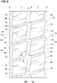
- FIG. 1 illustrates a development view of a tread portion 2 of a tyre 1 in accordance with an embodiment of the invention.
- the tyre 1 according to the present embodiment may preferably be used for a pneumatic tyre for passenger car. Additionally, the tyre 1 according to the present embodiment is not designated by neither a mounting direction to a vehicle nor rotational direction thereof. Thus, the tyre 1 has a point symmetrical tread pattern with respect to a point on the tyre equator C.
- the tread portion 2 of the tyre 1 is provided with main grooves 3 extending continuously in the tyre circumferential direction.
- the main grooves 3, for example, include two shoulder main grooves 4 and one crown main groove 5 disposed between the shoulder main grooves 4.
- Each of the shoulder main grooves 4, for example, is arranged between the tyre equator C and a respective one of the tread edges Te.
- the crown main groove 5 is arranged between the shoulder main grooves 4 on the tyre equator C.
- the tread edges Te are defined as axially outermost edges of the ground contacting patch of the tread portion 2 which occurs under a normal state with a standard tyre load when the camber angle of the tyre is zero.
- the normal state is such that the tyre is mounted on a standard wheel rim with a standard pressure but loaded with no tyre load.
- the standard wheel rim is a wheel rim officially approved for each tyre by standards organizations on which the tyre is based, wherein the standard wheel rim is the "standard rim” specified in JATMA, the "Design Rim” in TRA, and the “Measuring Rim” in ETRTO, for example.
- the standard pressure is a standard pressure officially approved for each tyre by standards organizations on which the tyre is based, wherein the standard pressure is the "maximum air pressure" in JATMA, the maximum pressure given in the "Tyre Load Limits at Various Cold Inflation Pressures” table in TRA, and the “Inflation Pressure” in ETRTO, for example.
- the standard tyre load is a tyre load officially approved for each tyre by standards organizations in which the tyre is based, wherein the standard tyre load is the "maximum load capacity" in JATMA, the maximum value given in the above-mentioned table in TRA, the "Load Capacity" in ETRTO, for example.
- a distance L1 in the tyre axial direction from the tyre equator C to a respective one of the shoulder main groove centerlines is in a range of 0.20 to 0.30 times the tread width TW.
- the tread width TW is a distance in the tyre axial direction between the tread edges Te of the tyre 1 under the normal state.
- groove widths W1 and W2 of the crown main groove 5 and the shoulder main grooves 4, respectively, are in a range of 4% to 7% of the tread width TW, for example.
- depths of the main grooves for example, are in a range of 5 to 10 mm.
- the groove width W2 of the shoulder main grooves 4 may be greater than the groove width W1 of the crown main groove 5. This may improve wear resistance and on-snow performance in a well-balanced manner.
- the crown main groove 5 extends in a zigzag manner in the tyre circumferential direction.
- the crown main groove 5 includes first groove elements 5a inclined with respect to the tyre circumferential direction, and second groove elements 5b inclined with respect to the tyre circumferential direction at a greater angle than that of the first groove elements 5a.
- the first groove elements 5a and the second groove elements 5b are alternated in the tyre circumferential direction.
- an angle of the first groove elements 5a for example, is in a range of 5 to 15 degrees with respect to the tyre circumferential direction.
- an angle of the second groove elements 5b for example, is in a range of 80 to 90 degrees with respect to the tyre circumferential direction.
- the crown main groove 5 as such can help to improve snow traction.
- Each of the shoulder main grooves 4 includes a plurality of inclined elements 4a arranged in the tyre circumferential direction.
- Each of the inclined elements 4a is inclined at an angle equal to or less than 10 degrees with respect to the tyre circumferential direction.
- the inclined elements 4a adjacent to one another in the tyre circumferential direction are coupled together so as to form a pair of zigzag groove edges.
- the angle of the inclined elements 4a of the shoulder main grooves 4 with respect to the tyre circumferential direction is smaller than the angle of the first groove elements 5a of the crown main groove 5 with respect to the tyre circumferential direction. This structure may be helpful to uniform wear of the crown main groove 5 and the shoulder main grooves 4, improving uneven wear resistance.
- the tread portion 2 includes a plurality of land portions 6 which is divided by the main grooves 3.
- the tread portion 2 according to the present embodiment includes four land portions 6 divided by three main grooves 3 as described above. Note that the present invention is not particularly limited but can be modified in such a manner that the tread portion 2, for example, may include five or more land portions 6 divided by four or more main grooves 3.
- the tread portion 2 includes two crown land portion 7 and two the shoulder land portions 8.
- the land portions consist of two crown land portion 7 and two the shoulder land portions 8.
- Each crown land portion is defined between two main grooves 3, e.g., between the crown main groove 5 and a respective one of the shoulder main grooves 4 in the present embodiment.
- the shoulder land portions 8 are defined between the shoulder main grooves 4 and the tread edges Te.
- FIG. 2 illustrates an enlarged view of the crown land portions 7.
- each crown land portion 7 is provided with a plurality of crown lateral grooves 10 traversing the crown land portion.
- each crown land portion 7 is divided into a plurality of crown blocks 13.
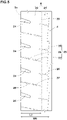
- FIG. 3 illustrates a cross-sectional view of one of the crown lateral grooves 10 taken along line A-A of FIG. 2 .
- each of the crown lateral grooves 10 in a cross-sectional view perpendicular to its longitudinal direction, includes a sipe portion 12 having a width W4 equal to or less than 1.5 mm, and a main portion 11 connected to the sipe portion 12 and opening at a ground contact surface of the crown land portion 7.
- the main portion 11 has a width enlarging from the sipe portion 12.
- the main portion 11 has a depth d1 smaller than depths of the main grooves 3.
- the sipe portion 12 has a first wall 12a extending in the tyre radial direction so as to be continuous with a first wall 11a of the main portion 11 to form a single groove wall (e.g., a flatted groove wall) together.
- the sipe portion 12 has s small width that is capable of closing upon grounding, thus preventing excessive reduction in stiffness of the crown land portion 7. Further, the main portion 11 has a smaller depth than that of the main grooves 3, preventing reduction in stiffness of the crown land portion 7. Accordingly, reduction of wear resistance of the crown land portion 7 due to reduction in stiffness by the crown lateral grooves 10 can be prevented.
- the crown lateral grooves 10 can provide reaction force (snow-column shearing force) by compacting and shearing snow when driving on snow, improving on-snow performance. Further, since the crown lateral grooves 10 according to the present invention each are configured such that the first wall 12a of the sipe portion 12 extending in the tyre radial direction is continuous with the first wall 11a of the main portion 11 to form a single groove wall, each sipe portion 12 can open each crown lateral groove 10 sufficiently wide upon a groove edge of each crown lateral groove 10 receives shearing force in the tyre circumferential direction. Thus, the difference between the volume when the crown lateral grooves 10 are opened and the volume when the crown lateral grooves 10 are closed increases. Accordingly, when driving on snow, the crown lateral grooves 10 can capture more snow and compress it strongly, providing a large snow-column shearing force and improving on-snow performance.
- the crown lateral grooves 10 are connected to the respective second groove elements 5b of the crown main groove 5. Additionally, the crown lateral grooves 10 are preferably connected to the respective connected portions between the adjacent two inclined elements 4a of the shoulder main groove 4. Such crown lateral grooves 10, when driving on snow, can form firm snow columns at the respective connected portions of the main grooves, improving on-snow performance.
- each crown lateral groove 10 is inclined with respect to the tyre axial direction. It is preferable that the main portion 11, with respect to the tyre axial direction, is inclined in an opposite direction to a direction of each second groove element 5b of the crown main groove 5.
- the first wall 11a of the main portion 11 is connected to a groove wall 5c of a respective one of the second groove elements 5b, and the first wall 11a of the main portion 11, with respect to the tyre axial direction, extends at a different angle from an angle of the groove wall 5c of a respective one of the second groove elements 5b.
- an angle of each main portion 11 with respect to the tyre axial direction is greater than an angle of each second groove element 5b with respect to the tyre axial direction. More specifically, the angle of crown lateral grooves 10 is in a range from 15 to 25 degrees with respect to the tyre axial direction. Such crown lateral grooves 10 can improve traction and cornering performance on snow.
- each main portion 11 includes the first wall 11a extending along (e.g., parallel with) the tyre radial direction from the sipe portion 12, a bottom 11b extending from the sipe portion 12 in parallel with a ground contact surface of the crown land portion 7, and a second wall 11c connected to the bottom 11b.
- the structure of the main portion 11 is not limited to such an aspect, but can be modified such that the main portion 11, for example, includes the first wall 11a extending along (e.g., parallel with) the tyre radial direction and an oblique wall (not illustrated) extending obliquely from the sipe portion 12.
- an opening width W3 of each main portion 11 is preferably smaller than a groove width W1 of the crown main groove 5 (shown in FIG. 1 ). More specifically, the opening width W3 of each main portion 11 is preferably in a range from 0.50 to 0.80 times the groove width W1 of the crown main groove 5, more preferably in a range from 0.60 to 0.70 times. Such a main portion 11 can help to improve wear resistance and on-snow performance in a well-balanced manner.
- each main portion 11 is preferably in a range from 0.25 to 0.60 times a depth of the crown main groove 5.
- Each sipe portion 12 extends in the tyre radial direction with a constant width.
- the width W4 of each sipe portion 12 is in a range from 0.5 to 1.5 mm, more preferably from 0.8 to 1.2 mm.
- each crown lateral groove 10 is preferably equal to or greater than 0.70 times the depth of the crown main groove 5, more preferably equal to or greater than 0.80 times, but preferably equal to or less than 1.10 times, more preferably equal to or less than 1.00 times.
- the above-mentioned maximum depth d2 corresponds to a depth from a ground contact surface of the land portion to the bottom of the sipe portion 12.
- FIG. 4 illustrates an enlarged view of the crown land portions 7 after the main portions 11 of the crown lateral grooves 10 worn. As illustrated in FIG. 4 , in the crown land portions 7, after the main portions 11 worn out, the sipe portions 12 still remain on the ground contact surface so as to provide friction by the edges.
- one of the crown land portions 7 is provided with the crown lateral grooves 10 each having the sipe portion 12 on a first side in the tyre circumferential direction with respect to a groove centerline thereof. Further, the other one of the crown land portions is provided with the crown lateral grooves 10 each having the sipe portion 12 on a second side opposite the first side in the tyre circumferential direction with respect to a groove centerline thereof.
- Such an arrangement of the sipe portions 12 can help to prevent uneven wear of the crown land portions 7.
- the crown main groove 5, for example, is provided with partial tie-bars 14 in which bottoms thereof raise partially.
- the partial tie-bars 14 are connected to either one of the crown land portions 7, for example.
- the partial tie-bars 14 are provided in a staggered manner such that the partial tie-bars 14, in the tyre circumferential direction, appear alternatively either side of the groove walls of the crown main groove 5.
- the partial tie-bars 14 are provided on end portions in the tyre circumferential direction of the respective first groove elements 5a.
- Such partial tie-bars 14, when driving on snow, can help to form firm snow columns around the second groove elements 5b, improving on-snow performance.
- each of the partial tie-bars 14 preferably has a maximum length which is measured along a longitudinal direction of the respective one of the first groove elements 5a greater than the groove width W1 of the crown main groove 5. Further, the maximum length is preferably in a range from 0.10 to 0.50 times the length of the respective one of the first groove elements 5a. Furthermore, in each of the partial tie-bars 14, it is preferable that a length which is measured along the longitudinal direction of the respective one of the first groove elements 5a decreases gradually toward the groove centerline of the respective one of the first groove elements 5a.
- a width W5 of the partial tie-bars 14 which is measured parallel to a width direction of the first groove elements 5a, for example, is preferably in a range from 0.20 to 0.40 times the groove width W1 of the crown main groove 5.
- a height of the partial tie-bars from a bottom of the crown main groove 5, for example, is preferably in a range of from 0.10 to 0.50 times a maximum depth of the crown main groove 5.
- the crown land portion 7, for example, is provided with a plurality of crown sipes 15.
- the plurality of crown sipes 15, for example, extends from the crown main groove 5 or the respective shoulder main grooves 4, and terminates within the crown land portion 7.
- the crown sipes 15 configured as such can generate friction force using its edges while preventing uneven wear of the crown land portion 7.
- “sipe” shall mean a narrow cut or incision that has a width equal to or less than 1.5 mm.
- each of the crown sipes 15 preferably includes a portion extending in a zigzag manner, for example.
- the crown sipes 15, for example, includes first crown sipes 16 extending from the crown main groove 5, and second crown sipes 17 extending from the respective shoulder main grooves 4.
- the first crown sipes 16 and the second crown sipes 17 are arranged in a staggered manner in the tyre circumferential direction.
- a minimum distance between a respective one of the partial tie-bars 14 and a respective one of the first crown sipes 16 which are adjacent with one another, in a plan view of the tread portion 2, is equal to or less than 2.0 mm.
- Such an arrangement of the first crown sipes 16 can make the movement of partial tie-bars 14 easy, which helps to form firm snow columns in the crown main grooves 5.
- the crown sipes 15 (the first crown sipes 16) extend from corners formed between the crown land portion 7 and the respective partial tie-bars 14.
- FIG. 5 illustrates an enlarged view of one of the shoulder land portions 8.
- each of the shoulder land portions 8 according to the present embodiment, for example, is provided with a single longitudinal narrow groove 20 extending continuously in the tyre circumferential direction.
- each of the shoulder land portions 8 is divided into a first land portion 21 disposed between the shoulder main groove 4 and the longitudinal narrow groove 20, and a second land portion 22 disposed between the longitudinal narrow groove 20 and the tread edge Te.
- the longitudinal narrow groove 20 has a groove width ranging from 1.0 to 2.0 mm, for example.
- the longitudinal narrow groove 20, for example is preferably arranged on the shoulder main groove side with respect to the center location of the shoulder land portion 8 in the tyre axial direction.
- a distance L2 in the tyre axial direction from the tread edge Te to the groove centerline of the longitudinal narrow groove 20 is in a range from 0.60 to 0.80 times a width W6 in the tyre axial direction of the shoulder land portion 8.
- Each of the shoulder land portions 8 according to the present embodiment is further provided with a plurality of shoulder lateral grooves 24 and a plurality of shoulder sipes 25.
- the shoulder lateral grooves 24 and the shoulder sipes 25, for example, are inclined with respect to the tyre axial direction in an opposite direction to an inclination direction of the crown lateral grooves 10.
- the shoulder lateral grooves 24 terminate on the tread edge side with respect to the center location in the tyre axial direction of the shoulder land portion 8.
- the shoulder lateral grooves 24 has a groove width decreasing continuously toward the tyre equator C.
- the first land portion 21 tends to deflect suitably when driving, preventing snow clogging in the shoulder main grooves 4.
- the shoulder sipes 25, for example, include first shoulder sipes 26, second shoulder sipes 27 and third shoulder sipes 28.
- the first shoulder sipes 26, for example, extend from the shoulder main groove 4 across the first land portion 21 and the longitudinal narrow groove 20, and terminate within the second land portion 22.
- the second shoulder sipes 27, for example, extend from the longitudinal narrow groove 20 toward the tread edge Te, and terminate within the second land portion 22.
- the shoulder sipes 25 configured as such can improve on-snow performance while maintaining sufficient stiffness of the shoulder land portion 8.
- the first shoulder sipes 26, for example, extend straight.
- the second shoulder sipes 27 and the third shoulder sipes 28, for example, extend in a zigzag manner.
- block pieces divided by the first shoulder sipes 26 tend to deflect easily inwardly in the tyre axial direction by being pushed by the second land portion 22, preventing snow clogging in the shoulder main groove 4.
- Tyres, 235/65R16C, having a basic pattern of FIG. 1 were prototyped based on the specification shown in Table 1.
- a tyre provided with crown lateral grooves (a) having a cross-section shown in FIG. 6 was also prototyped.
- the crown lateral grooves (a) of the comparative example each include a main portion (b) and a sipe portion (c) provided on the center location in a width direction of the main portion (b).
- the comparative example tyre has the same tread pattern as the tread pattern shown in FIG. 1 , except for the above-mentioned structure. Then, on-snow performance and wear resistance of each test tyre was tested.
- the common specification are as follows:
- the test procedure are as follows.
- the acceleration was measured when the test vehicle accelerated from 8 km/h to 32 km/h on a snowy road.
- the test results are indicated in Table 1 using an index where the acceleration of the comparative example set to 100. The larger the value indicates the better the on-snow performance.
- the wear energy of the crown land portion of each test tyre was measured using a wear energy measuring device.
- the test results are indicated in Table 1 using an index where the wear energy of the comparative example is set to 100. The smaller the value indicates the better the wear resistance.
- Table 1 shows the test results. [Table 1] (1/2) Ref. Ex. 1 Ex. 2 Ex. 3 Ex. 4 Ex. 5 Ex. 6 Ex. 7 Crown lateral groove cross-sectional view FIG. 6 FIG. 3 FIG. 3 FIG. 3 FIG. 3 FIG. 3 FIG. 3 FIG. 3 FIG. 3 FIG. 3 FIG. 3 FIG. 3 FIG. 3 FIG.
- FIG. 3 FIG. 3 FIG. 3 FIG. 3 FIG. 3 FIG. 3 Main portion opening widths W3 / crown lateral groove widths W1 0.65 0.65 0.65 0.65 0.65 0.65 0.65 0.65 0.65 0.65 Sipe portion widths W4 (mm) 1.2 1.5 1.0 1.0 1.0 1.0 1.0 1.0 1.0 Crown lateral groove depths d2 / crown main groove depth 0.90 0.90 0.70 0.80 1.00 1.10 0.90 Partial tie-bars presence presence presence presence presence presence presence presence presence none On-snow performance (index) 107 108 105 107 107 108 105 Wear resistance (index) 98 101 98 98 98 103 98
- the example tyres improve on-snow performance while maintaining wear resistance compared with the comparative example tyre.
- the tyres of the example can exhibit excellent on-snow performance while preventing a decrease in wear resistance.
Landscapes
- Engineering & Computer Science (AREA)
- Mechanical Engineering (AREA)
- Tires In General (AREA)
Claims (8)
- Reifen (1), umfassend:einen Laufflächenabschnitt (2), der mindestens einen Kronenlandabschnitt (7) umfasst, der zwischen zwei Hauptrillen (3) definiert ist, die sich kontinuierlich in einer Reifenumfangsrichtung erstrecken, wobei die Hauptrillen (3) eine Kronenhauptrille (5) umfassen, die in Bezug auf den mindestens einen Kronenlandabschnitt (7) auf derselben Seite wie ein Reifenäquator (C) angeordnet ist,wobei der mindestens eine Kronenabschnitt (7) mit Kronenquerrillen (10) versehen ist, die den mindestens einen Kronenabschnitt (7) queren,wobei eine jede der Kronenquerrillen (10) in einer Querschnittsansicht senkrecht zu ihrer Längsrichtung einen Feinschnittabschnitt (12) mit einer Breite (W4) von gleich oder kleiner als 1,5 mm und einen Hauptabschnitt (11) umfasst, der mit dem Feinschnittabschnitt (12) verbunden ist und sich an einer Bodenkontaktfläche des mindestens einen Kronenlandabschnitts (7) öffnet, wobeider Hauptabschnitt (11) eine Breite aufweist, die sich von dem Feinschnittabschnitt (12) aus vergrößert,der Hauptabschnitt (11) eine Tiefe (d1) aufweist, die kleiner ist als die Tiefe der Hauptrillen (3), undder Feinschnittabschnitt (12) eine erste Wand (12a) aufweist, die sich in einer radialen Richtung des Reifens so erstreckt, dass sie mit einer ersten Wand (11a) des Hauptabschnitts (11) zusammenhängend ist, um zusammen eine einzige Rillenwand zu bilden,dadurch gekennzeichnet, dass die Kronenhauptrille (5) erste Rillenelemente (5a), die in Bezug auf die Reifenumfangsrichtung geneigt sind, und zweite Rillenelemente (5b) umfasst, die in Bezug auf die Reifenumfangsrichtung unter einem größeren Winkel als der der ersten Rillenelemente (5a) geneigt sind, unddie ersten Rillenelemente (5a) und die zweiten Rillenelemente (5b) abwechselnd in der Reifenumfangsrichtung angeordnet sind.
- Reifen (1) nach Anspruch 1, wobei
die Kronenquerrillen (10) mit den jeweiligen zweiten Rillenelementen (5b) verbunden sind. - Reifen (1) nach Anspruch 2, wobeidie erste Wand (11a) des Hauptabschnitts (11) einer jeden der Kronenquerrillen (10) mit einer Rillenwand (5c) eines jeweiligen der zweiten Rillenelemente (5b) verbunden ist, unddie erste Wand (11a) des Hauptabschnitts (11) einer jeden der Kronenquerrillen (10) sich in Bezug auf die axiale Richtung des Reifens unter einem anderen Winkel als der Winkel eines jeweiligen der zweiten Rillenelemente (5b) erstreckt.
- Reifen (1) nach einem der Ansprüche 1 bis 3, wobeidie Kronenhauptrille (5) mit Teilanbindungsstegen (14) versehen ist, in denen sich deren Böden teilweise erheben,die Teilanbindungsstege (14) mit dem mindestens einen Kronenabschnitt (7) verbunden sind, unddie Teilanbindungsstege (14) an Endabschnitten in Reifenumfangsrichtung der jeweiligen ersten Rillenelemente (5a) vorgesehen sind.
- Reifen (1) nach Anspruch 4, wobeider mindestens eine Kronenlandabschnitt (7) mit Kronenfeinschnitten (15) versehen ist, die sich von der Kronenhauptrille (5) aus erstrecken, undein minimaler Abstand zwischen einem jeweiligen der Teilanbindungsstege (14) und einem jeweiligen der Kronenfeinschnitte (15), die in einer Draufsicht auf den Laufflächenabschnitt (2) einander benachbart sind, gleich oder kleiner als 2,0 mm ist.
- Reifen (1) nach einem der Ansprüche 1 bis 5, wobei eine maximale Tiefe (d2) der Kronenquerrillen (10) in einem Bereich vom 0,80- bis 1,00-fachen der Tiefe der Kronenhauptrille (5) liegt.
- Reifen (1) nach einem der Ansprüche 1 bis 6, wobei der mindestens eine Kronenlandabschnitt (7) zwei Kronenlandabschnitte (7) umfasst.
- Reifen (1) nach Anspruch 7, wobeieiner der Kronenlandabschnitte (7) mit den Kronenquerrillen (10) versehen ist, die jeweils den Feinschnittabschnitt (12) auf einer ersten Seite in der Reifenumfangsrichtung in Bezug auf eine Rillenmittellinie davon aufweisen, undder andere der Kronenlandabschnitte (7) mit den Kronenquerrillen (10) versehen ist, die jeweils den Feinschnittabschnitt (12) auf einer zweiten Seite gegenüber der ersten Seite in der Reifenumfangsrichtung in Bezug auf eine Rillenmittellinie davon aufweisen.
Applications Claiming Priority (2)
| Application Number | Priority Date | Filing Date | Title |
|---|---|---|---|
| JP2019091582A JP7275834B2 (ja) | 2019-05-14 | 2019-05-14 | タイヤ |
| EP20169250.6A EP3738792B1 (de) | 2019-05-14 | 2020-04-14 | Reifen |
Related Parent Applications (2)
| Application Number | Title | Priority Date | Filing Date |
|---|---|---|---|
| EP20169250.6A Division-Into EP3738792B1 (de) | 2019-05-14 | 2020-04-14 | Reifen |
| EP20169250.6A Division EP3738792B1 (de) | 2019-05-14 | 2020-04-14 | Reifen |
Publications (2)
| Publication Number | Publication Date |
|---|---|
| EP3828011A1 EP3828011A1 (de) | 2021-06-02 |
| EP3828011B1 true EP3828011B1 (de) | 2022-10-05 |
Family
ID=70289296
Family Applications (2)
| Application Number | Title | Priority Date | Filing Date |
|---|---|---|---|
| EP20169250.6A Active EP3738792B1 (de) | 2019-05-14 | 2020-04-14 | Reifen |
| EP21152672.8A Active EP3828011B1 (de) | 2019-05-14 | 2020-04-14 | Reifenlauffläche |
Family Applications Before (1)
| Application Number | Title | Priority Date | Filing Date |
|---|---|---|---|
| EP20169250.6A Active EP3738792B1 (de) | 2019-05-14 | 2020-04-14 | Reifen |
Country Status (4)
| Country | Link |
|---|---|
| US (1) | US11407256B2 (de) |
| EP (2) | EP3738792B1 (de) |
| JP (1) | JP7275834B2 (de) |
| CN (1) | CN111942084B (de) |
Families Citing this family (3)
| Publication number | Priority date | Publication date | Assignee | Title |
|---|---|---|---|---|
| USD943506S1 (en) * | 2019-10-24 | 2022-02-15 | Bridgestone Europe Nv/Sa | Tire |
| JP7188534B1 (ja) * | 2021-10-25 | 2022-12-13 | 住友ゴム工業株式会社 | タイヤ |
| DE102021212465A1 (de) * | 2021-11-05 | 2023-05-11 | Continental Reifen Deutschland Gmbh | Fahrzeugluftreifen |
Family Cites Families (30)
| Publication number | Priority date | Publication date | Assignee | Title |
|---|---|---|---|---|
| US5492161A (en) * | 1985-01-19 | 1996-02-20 | Toyo Tire & Rubber Company, Limited | Pneumatic tire with groove steps having sipes |
| CN101341035B (zh) * | 2005-12-20 | 2010-07-28 | 住友橡胶工业株式会社 | 重载荷用轮胎 |
| US20100154951A1 (en) * | 2006-01-17 | 2010-06-24 | Bridgestone Corporation | Pneumatic tire |
| JP4938387B2 (ja) * | 2006-08-31 | 2012-05-23 | 東洋ゴム工業株式会社 | 空気入りタイヤ |
| JP2008207659A (ja) * | 2007-02-26 | 2008-09-11 | Bridgestone Corp | 空気入りタイヤ |
| JP5144116B2 (ja) * | 2007-04-26 | 2013-02-13 | 株式会社ブリヂストン | 空気入りタイヤ |
| US9481210B2 (en) * | 2010-02-26 | 2016-11-01 | Bridgestone Corporation | Pneumatic tire |
| JP5856787B2 (ja) * | 2011-09-26 | 2016-02-10 | 東洋ゴム工業株式会社 | 空気入りタイヤ |
| JP5764159B2 (ja) * | 2013-05-08 | 2015-08-12 | 住友ゴム工業株式会社 | 空気入りタイヤ |
| CN105324253B (zh) * | 2013-07-05 | 2018-08-28 | 住友橡胶工业株式会社 | 充气轮胎 |
| JP6190194B2 (ja) * | 2013-07-22 | 2017-08-30 | 住友ゴム工業株式会社 | 空気入りタイヤ |
| JP5938030B2 (ja) * | 2013-12-27 | 2016-06-22 | 住友ゴム工業株式会社 | 空気入りタイヤ |
| US9636952B2 (en) * | 2014-01-08 | 2017-05-02 | Sumitomo Rubber Industries, Ltd. | Heavy duty pneumatic tire |
| JP6235985B2 (ja) * | 2014-11-06 | 2017-11-22 | 住友ゴム工業株式会社 | 空気入りタイヤ |
| JP6231974B2 (ja) | 2014-11-27 | 2017-11-15 | 住友ゴム工業株式会社 | 空気入りタイヤ |
| JP6130824B2 (ja) * | 2014-12-09 | 2017-05-17 | 住友ゴム工業株式会社 | 重荷重用空気入りタイヤ |
| CN106080046B (zh) | 2015-04-30 | 2019-07-16 | 住友橡胶工业株式会社 | 充气轮胎 |
| JP6312646B2 (ja) * | 2015-10-14 | 2018-04-18 | 住友ゴム工業株式会社 | 空気入りタイヤ |
| JP6724451B2 (ja) * | 2016-03-18 | 2020-07-15 | 住友ゴム工業株式会社 | 空気入りタイヤ |
| JP6772599B2 (ja) | 2016-07-01 | 2020-10-21 | 住友ゴム工業株式会社 | 空気入りタイヤ |
| US10814675B2 (en) * | 2016-07-12 | 2020-10-27 | Sumitomo Rubber Industries, Ltd. | Tire |
| JP6740761B2 (ja) * | 2016-07-12 | 2020-08-19 | 住友ゴム工業株式会社 | タイヤ |
| JP6814577B2 (ja) * | 2016-09-14 | 2021-01-20 | Toyo Tire株式会社 | 空気入りタイヤ |
| JP6834291B2 (ja) * | 2016-09-21 | 2021-02-24 | 住友ゴム工業株式会社 | 空気入りタイヤ |
| JP6816506B2 (ja) * | 2016-12-29 | 2021-01-20 | 住友ゴム工業株式会社 | タイヤ |
| CN108263146B (zh) | 2016-12-29 | 2022-03-01 | 住友橡胶工业株式会社 | 轮胎 |
| JP6880999B2 (ja) * | 2017-04-28 | 2021-06-02 | 住友ゴム工業株式会社 | タイヤ |
| WO2018225371A1 (ja) * | 2017-06-06 | 2018-12-13 | 横浜ゴム株式会社 | 空気入りタイヤ |
| EP3489036B1 (de) * | 2017-11-27 | 2020-05-20 | Sumitomo Rubber Industries Ltd. | Reifen |
| EP3489037B1 (de) * | 2017-11-27 | 2020-08-26 | Sumitomo Rubber Industries Limited | Reifen |
-
2019
- 2019-05-14 JP JP2019091582A patent/JP7275834B2/ja active Active
-
2020
- 2020-04-02 US US16/838,569 patent/US11407256B2/en active Active
- 2020-04-02 CN CN202010254486.7A patent/CN111942084B/zh active Active
- 2020-04-14 EP EP20169250.6A patent/EP3738792B1/de active Active
- 2020-04-14 EP EP21152672.8A patent/EP3828011B1/de active Active
Also Published As
| Publication number | Publication date |
|---|---|
| EP3738792B1 (de) | 2023-05-31 |
| JP7275834B2 (ja) | 2023-05-18 |
| EP3828011A1 (de) | 2021-06-02 |
| JP2020185882A (ja) | 2020-11-19 |
| CN111942084B (zh) | 2023-11-28 |
| CN111942084A (zh) | 2020-11-17 |
| US11407256B2 (en) | 2022-08-09 |
| EP3738792A1 (de) | 2020-11-18 |
| US20200361244A1 (en) | 2020-11-19 |
Similar Documents
| Publication | Publication Date | Title |
|---|---|---|
| EP3260308B1 (de) | Reifen | |
| EP3153334B1 (de) | Reifen | |
| EP3025879B1 (de) | Luftreifen | |
| EP3388257B1 (de) | Reifen | |
| EP3421263B1 (de) | Reifen | |
| EP3263367B1 (de) | Luftreifen | |
| EP2578418B1 (de) | Luftreifen | |
| EP2664464B1 (de) | Luftreifen | |
| EP3398793B1 (de) | Reifen | |
| EP3012119B1 (de) | Luftreifen | |
| EP3135504B1 (de) | Schwerlastreifen | |
| EP3539798B1 (de) | Reifen | |
| EP3521064A1 (de) | Reifen | |
| EP2692543B1 (de) | Luftreifen | |
| EP3560732B1 (de) | Reifen | |
| EP3828011B1 (de) | Reifenlauffläche | |
| EP3248810A1 (de) | Reifen | |
| EP3444131A1 (de) | Reifen | |
| EP3575110B1 (de) | Reifen | |
| EP3549791B1 (de) | Reifen | |
| EP3263366B1 (de) | Reifen | |
| EP3025878B1 (de) | Schwerlastluftreifen | |
| EP3636459B1 (de) | Reifen | |
| EP3711981B1 (de) | Reifen |
Legal Events
| Date | Code | Title | Description |
|---|---|---|---|
| PUAI | Public reference made under article 153(3) epc to a published international application that has entered the european phase |
Free format text: ORIGINAL CODE: 0009012 |
|
| STAA | Information on the status of an ep patent application or granted ep patent |
Free format text: STATUS: THE APPLICATION HAS BEEN PUBLISHED |
|
| AC | Divisional application: reference to earlier application |
Ref document number: 3738792 Country of ref document: EP Kind code of ref document: P |
|
| AK | Designated contracting states |
Kind code of ref document: A1 Designated state(s): AL AT BE BG CH CY CZ DE DK EE ES FI FR GB GR HR HU IE IS IT LI LT LU LV MC MK MT NL NO PL PT RO RS SE SI SK SM TR |
|
| STAA | Information on the status of an ep patent application or granted ep patent |
Free format text: STATUS: REQUEST FOR EXAMINATION WAS MADE |
|
| 17P | Request for examination filed |
Effective date: 20210625 |
|
| RBV | Designated contracting states (corrected) |
Designated state(s): AL AT BE BG CH CY CZ DE DK EE ES FI FR GB GR HR HU IE IS IT LI LT LU LV MC MK MT NL NO PL PT RO RS SE SI SK SM TR |
|
| GRAP | Despatch of communication of intention to grant a patent |
Free format text: ORIGINAL CODE: EPIDOSNIGR1 |
|
| STAA | Information on the status of an ep patent application or granted ep patent |
Free format text: STATUS: GRANT OF PATENT IS INTENDED |
|
| RIC1 | Information provided on ipc code assigned before grant |
Ipc: B60C 11/13 20060101ALN20220712BHEP Ipc: B60C 11/12 20060101ALI20220712BHEP Ipc: B60C 11/03 20060101AFI20220712BHEP |
|
| INTG | Intention to grant announced |
Effective date: 20220729 |
|
| GRAS | Grant fee paid |
Free format text: ORIGINAL CODE: EPIDOSNIGR3 |
|
| GRAA | (expected) grant |
Free format text: ORIGINAL CODE: 0009210 |
|
| STAA | Information on the status of an ep patent application or granted ep patent |
Free format text: STATUS: THE PATENT HAS BEEN GRANTED |
|
| AC | Divisional application: reference to earlier application |
Ref document number: 3738792 Country of ref document: EP Kind code of ref document: P |
|
| AK | Designated contracting states |
Kind code of ref document: B1 Designated state(s): AL AT BE BG CH CY CZ DE DK EE ES FI FR GB GR HR HU IE IS IT LI LT LU LV MC MK MT NL NO PL PT RO RS SE SI SK SM TR |
|
| REG | Reference to a national code |
Ref country code: GB Ref legal event code: FG4D |
|
| REG | Reference to a national code |
Ref country code: CH Ref legal event code: EP |
|
| REG | Reference to a national code |
Ref country code: AT Ref legal event code: REF Ref document number: 1522531 Country of ref document: AT Kind code of ref document: T Effective date: 20221015 |
|
| REG | Reference to a national code |
Ref country code: IE Ref legal event code: FG4D |
|
| REG | Reference to a national code |
Ref country code: DE Ref legal event code: R096 Ref document number: 602020005523 Country of ref document: DE |
|
| REG | Reference to a national code |
Ref country code: LT Ref legal event code: MG9D |
|
| REG | Reference to a national code |
Ref country code: NL Ref legal event code: MP Effective date: 20221005 |
|
| REG | Reference to a national code |
Ref country code: AT Ref legal event code: MK05 Ref document number: 1522531 Country of ref document: AT Kind code of ref document: T Effective date: 20221005 |
|
| PG25 | Lapsed in a contracting state [announced via postgrant information from national office to epo] |
Ref country code: NL Free format text: LAPSE BECAUSE OF FAILURE TO SUBMIT A TRANSLATION OF THE DESCRIPTION OR TO PAY THE FEE WITHIN THE PRESCRIBED TIME-LIMIT Effective date: 20221005 |
|
| PG25 | Lapsed in a contracting state [announced via postgrant information from national office to epo] |
Ref country code: SE Free format text: LAPSE BECAUSE OF FAILURE TO SUBMIT A TRANSLATION OF THE DESCRIPTION OR TO PAY THE FEE WITHIN THE PRESCRIBED TIME-LIMIT Effective date: 20221005 Ref country code: PT Free format text: LAPSE BECAUSE OF FAILURE TO SUBMIT A TRANSLATION OF THE DESCRIPTION OR TO PAY THE FEE WITHIN THE PRESCRIBED TIME-LIMIT Effective date: 20230206 Ref country code: NO Free format text: LAPSE BECAUSE OF FAILURE TO SUBMIT A TRANSLATION OF THE DESCRIPTION OR TO PAY THE FEE WITHIN THE PRESCRIBED TIME-LIMIT Effective date: 20230105 Ref country code: LT Free format text: LAPSE BECAUSE OF FAILURE TO SUBMIT A TRANSLATION OF THE DESCRIPTION OR TO PAY THE FEE WITHIN THE PRESCRIBED TIME-LIMIT Effective date: 20221005 Ref country code: FI Free format text: LAPSE BECAUSE OF FAILURE TO SUBMIT A TRANSLATION OF THE DESCRIPTION OR TO PAY THE FEE WITHIN THE PRESCRIBED TIME-LIMIT Effective date: 20221005 Ref country code: ES Free format text: LAPSE BECAUSE OF FAILURE TO SUBMIT A TRANSLATION OF THE DESCRIPTION OR TO PAY THE FEE WITHIN THE PRESCRIBED TIME-LIMIT Effective date: 20221005 Ref country code: AT Free format text: LAPSE BECAUSE OF FAILURE TO SUBMIT A TRANSLATION OF THE DESCRIPTION OR TO PAY THE FEE WITHIN THE PRESCRIBED TIME-LIMIT Effective date: 20221005 |
|
| PG25 | Lapsed in a contracting state [announced via postgrant information from national office to epo] |
Ref country code: RS Free format text: LAPSE BECAUSE OF FAILURE TO SUBMIT A TRANSLATION OF THE DESCRIPTION OR TO PAY THE FEE WITHIN THE PRESCRIBED TIME-LIMIT Effective date: 20221005 Ref country code: PL Free format text: LAPSE BECAUSE OF FAILURE TO SUBMIT A TRANSLATION OF THE DESCRIPTION OR TO PAY THE FEE WITHIN THE PRESCRIBED TIME-LIMIT Effective date: 20221005 Ref country code: LV Free format text: LAPSE BECAUSE OF FAILURE TO SUBMIT A TRANSLATION OF THE DESCRIPTION OR TO PAY THE FEE WITHIN THE PRESCRIBED TIME-LIMIT Effective date: 20221005 Ref country code: IS Free format text: LAPSE BECAUSE OF FAILURE TO SUBMIT A TRANSLATION OF THE DESCRIPTION OR TO PAY THE FEE WITHIN THE PRESCRIBED TIME-LIMIT Effective date: 20230205 Ref country code: HR Free format text: LAPSE BECAUSE OF FAILURE TO SUBMIT A TRANSLATION OF THE DESCRIPTION OR TO PAY THE FEE WITHIN THE PRESCRIBED TIME-LIMIT Effective date: 20221005 Ref country code: GR Free format text: LAPSE BECAUSE OF FAILURE TO SUBMIT A TRANSLATION OF THE DESCRIPTION OR TO PAY THE FEE WITHIN THE PRESCRIBED TIME-LIMIT Effective date: 20230106 |
|
| P01 | Opt-out of the competence of the unified patent court (upc) registered |
Effective date: 20230510 |
|
| REG | Reference to a national code |
Ref country code: DE Ref legal event code: R097 Ref document number: 602020005523 Country of ref document: DE |
|
| PG25 | Lapsed in a contracting state [announced via postgrant information from national office to epo] |
Ref country code: SM Free format text: LAPSE BECAUSE OF FAILURE TO SUBMIT A TRANSLATION OF THE DESCRIPTION OR TO PAY THE FEE WITHIN THE PRESCRIBED TIME-LIMIT Effective date: 20221005 Ref country code: RO Free format text: LAPSE BECAUSE OF FAILURE TO SUBMIT A TRANSLATION OF THE DESCRIPTION OR TO PAY THE FEE WITHIN THE PRESCRIBED TIME-LIMIT Effective date: 20221005 Ref country code: EE Free format text: LAPSE BECAUSE OF FAILURE TO SUBMIT A TRANSLATION OF THE DESCRIPTION OR TO PAY THE FEE WITHIN THE PRESCRIBED TIME-LIMIT Effective date: 20221005 Ref country code: DK Free format text: LAPSE BECAUSE OF FAILURE TO SUBMIT A TRANSLATION OF THE DESCRIPTION OR TO PAY THE FEE WITHIN THE PRESCRIBED TIME-LIMIT Effective date: 20221005 Ref country code: CZ Free format text: LAPSE BECAUSE OF FAILURE TO SUBMIT A TRANSLATION OF THE DESCRIPTION OR TO PAY THE FEE WITHIN THE PRESCRIBED TIME-LIMIT Effective date: 20221005 |
|
| PGFP | Annual fee paid to national office [announced via postgrant information from national office to epo] |
Ref country code: FR Payment date: 20230424 Year of fee payment: 4 Ref country code: DE Payment date: 20230627 Year of fee payment: 4 |
|
| PLBE | No opposition filed within time limit |
Free format text: ORIGINAL CODE: 0009261 |
|
| STAA | Information on the status of an ep patent application or granted ep patent |
Free format text: STATUS: NO OPPOSITION FILED WITHIN TIME LIMIT |
|
| PG25 | Lapsed in a contracting state [announced via postgrant information from national office to epo] |
Ref country code: SK Free format text: LAPSE BECAUSE OF FAILURE TO SUBMIT A TRANSLATION OF THE DESCRIPTION OR TO PAY THE FEE WITHIN THE PRESCRIBED TIME-LIMIT Effective date: 20221005 Ref country code: AL Free format text: LAPSE BECAUSE OF FAILURE TO SUBMIT A TRANSLATION OF THE DESCRIPTION OR TO PAY THE FEE WITHIN THE PRESCRIBED TIME-LIMIT Effective date: 20221005 |
|
| 26N | No opposition filed |
Effective date: 20230706 |
|
| PG25 | Lapsed in a contracting state [announced via postgrant information from national office to epo] |
Ref country code: SI Free format text: LAPSE BECAUSE OF FAILURE TO SUBMIT A TRANSLATION OF THE DESCRIPTION OR TO PAY THE FEE WITHIN THE PRESCRIBED TIME-LIMIT Effective date: 20221005 |
|
| REG | Reference to a national code |
Ref country code: CH Ref legal event code: PL |
|
| PG25 | Lapsed in a contracting state [announced via postgrant information from national office to epo] |
Ref country code: LU Free format text: LAPSE BECAUSE OF NON-PAYMENT OF DUE FEES Effective date: 20230414 |
|
| REG | Reference to a national code |
Ref country code: BE Ref legal event code: MM Effective date: 20230430 |
|
| PG25 | Lapsed in a contracting state [announced via postgrant information from national office to epo] |
Ref country code: MC Free format text: LAPSE BECAUSE OF FAILURE TO SUBMIT A TRANSLATION OF THE DESCRIPTION OR TO PAY THE FEE WITHIN THE PRESCRIBED TIME-LIMIT Effective date: 20221005 |
|
| PG25 | Lapsed in a contracting state [announced via postgrant information from national office to epo] |
Ref country code: MC Free format text: LAPSE BECAUSE OF FAILURE TO SUBMIT A TRANSLATION OF THE DESCRIPTION OR TO PAY THE FEE WITHIN THE PRESCRIBED TIME-LIMIT Effective date: 20221005 Ref country code: LI Free format text: LAPSE BECAUSE OF NON-PAYMENT OF DUE FEES Effective date: 20230430 Ref country code: CH Free format text: LAPSE BECAUSE OF NON-PAYMENT OF DUE FEES Effective date: 20230430 |
|
| REG | Reference to a national code |
Ref country code: IE Ref legal event code: MM4A |
|
| PG25 | Lapsed in a contracting state [announced via postgrant information from national office to epo] |
Ref country code: BE Free format text: LAPSE BECAUSE OF NON-PAYMENT OF DUE FEES Effective date: 20230430 |
|
| PG25 | Lapsed in a contracting state [announced via postgrant information from national office to epo] |
Ref country code: IE Free format text: LAPSE BECAUSE OF NON-PAYMENT OF DUE FEES Effective date: 20230414 |
|
| PG25 | Lapsed in a contracting state [announced via postgrant information from national office to epo] |
Ref country code: IE Free format text: LAPSE BECAUSE OF NON-PAYMENT OF DUE FEES Effective date: 20230414 |