EP3826936B1 - Gefaessverschluss mit dichtungselement - Google Patents
Gefaessverschluss mit dichtungselement Download PDFInfo
- Publication number
- EP3826936B1 EP3826936B1 EP19736490.4A EP19736490A EP3826936B1 EP 3826936 B1 EP3826936 B1 EP 3826936B1 EP 19736490 A EP19736490 A EP 19736490A EP 3826936 B1 EP3826936 B1 EP 3826936B1
- Authority
- EP
- European Patent Office
- Prior art keywords
- polymer composition
- vessel
- closure
- copolymer
- butene
- Prior art date
- Legal status (The legal status is an assumption and is not a legal conclusion. Google has not performed a legal analysis and makes no representation as to the accuracy of the status listed.)
- Active
Links
Images



Classifications
-
- B—PERFORMING OPERATIONS; TRANSPORTING
- B65—CONVEYING; PACKING; STORING; HANDLING THIN OR FILAMENTARY MATERIAL
- B65D—CONTAINERS FOR STORAGE OR TRANSPORT OF ARTICLES OR MATERIALS, e.g. BAGS, BARRELS, BOTTLES, BOXES, CANS, CARTONS, CRATES, DRUMS, JARS, TANKS, HOPPERS, FORWARDING CONTAINERS; ACCESSORIES, CLOSURES, OR FITTINGS THEREFOR; PACKAGING ELEMENTS; PACKAGES
- B65D51/00—Closures not otherwise provided for
- B65D51/14—Rigid discs or spherical members adapted to be held in sealing engagement with mouth of container, e.g. closure plates for preserving jars
- B65D51/145—Rigid discs or spherical members adapted to be held in sealing engagement with mouth of container, e.g. closure plates for preserving jars by means of an additional element connected directly to the container
-
- B—PERFORMING OPERATIONS; TRANSPORTING
- B65—CONVEYING; PACKING; STORING; HANDLING THIN OR FILAMENTARY MATERIAL
- B65D—CONTAINERS FOR STORAGE OR TRANSPORT OF ARTICLES OR MATERIALS, e.g. BAGS, BARRELS, BOTTLES, BOXES, CANS, CARTONS, CRATES, DRUMS, JARS, TANKS, HOPPERS, FORWARDING CONTAINERS; ACCESSORIES, CLOSURES, OR FITTINGS THEREFOR; PACKAGING ELEMENTS; PACKAGES
- B65D53/00—Sealing or packing elements; Sealings formed by liquid or plastics material
- B65D53/02—Collars or rings
-
- C—CHEMISTRY; METALLURGY
- C08—ORGANIC MACROMOLECULAR COMPOUNDS; THEIR PREPARATION OR CHEMICAL WORKING-UP; COMPOSITIONS BASED THEREON
- C08L—COMPOSITIONS OF MACROMOLECULAR COMPOUNDS
- C08L23/00—Compositions of homopolymers or copolymers of unsaturated aliphatic hydrocarbons having only one carbon-to-carbon double bond; Compositions of derivatives of such polymers
- C08L23/02—Compositions of homopolymers or copolymers of unsaturated aliphatic hydrocarbons having only one carbon-to-carbon double bond; Compositions of derivatives of such polymers not modified by chemical after-treatment
- C08L23/18—Homopolymers or copolymers of hydrocarbons having four or more carbon atoms
- C08L23/20—Homopolymers or copolymers of hydrocarbons having four or more carbon atoms having four to nine carbon atoms
-
- C—CHEMISTRY; METALLURGY
- C09—DYES; PAINTS; POLISHES; NATURAL RESINS; ADHESIVES; COMPOSITIONS NOT OTHERWISE PROVIDED FOR; APPLICATIONS OF MATERIALS NOT OTHERWISE PROVIDED FOR
- C09K—MATERIALS FOR MISCELLANEOUS APPLICATIONS, NOT PROVIDED FOR ELSEWHERE
- C09K3/00—Materials not provided for elsewhere
- C09K3/10—Materials in mouldable or extrudable form for sealing or packing joints or covers
- C09K3/1006—Materials in mouldable or extrudable form for sealing or packing joints or covers characterised by the chemical nature of one of its constituents
-
- B—PERFORMING OPERATIONS; TRANSPORTING
- B32—LAYERED PRODUCTS
- B32B—LAYERED PRODUCTS, i.e. PRODUCTS BUILT-UP OF STRATA OF FLAT OR NON-FLAT, e.g. CELLULAR OR HONEYCOMB, FORM
- B32B2435/00—Closures, end caps, stoppers
- B32B2435/02—Closures, end caps, stoppers for containers
-
- C—CHEMISTRY; METALLURGY
- C08—ORGANIC MACROMOLECULAR COMPOUNDS; THEIR PREPARATION OR CHEMICAL WORKING-UP; COMPOSITIONS BASED THEREON
- C08L—COMPOSITIONS OF MACROMOLECULAR COMPOUNDS
- C08L2201/00—Properties
- C08L2201/14—Gas barrier composition
-
- C—CHEMISTRY; METALLURGY
- C08—ORGANIC MACROMOLECULAR COMPOUNDS; THEIR PREPARATION OR CHEMICAL WORKING-UP; COMPOSITIONS BASED THEREON
- C08L—COMPOSITIONS OF MACROMOLECULAR COMPOUNDS
- C08L2205/00—Polymer mixtures characterised by other features
- C08L2205/02—Polymer mixtures characterised by other features containing two or more polymers of the same C08L -group
-
- C—CHEMISTRY; METALLURGY
- C08—ORGANIC MACROMOLECULAR COMPOUNDS; THEIR PREPARATION OR CHEMICAL WORKING-UP; COMPOSITIONS BASED THEREON
- C08L—COMPOSITIONS OF MACROMOLECULAR COMPOUNDS
- C08L2205/00—Polymer mixtures characterised by other features
- C08L2205/02—Polymer mixtures characterised by other features containing two or more polymers of the same C08L -group
- C08L2205/025—Polymer mixtures characterised by other features containing two or more polymers of the same C08L -group containing two or more polymers of the same hierarchy C08L, and differing only in parameters such as density, comonomer content, molecular weight, structure
-
- C—CHEMISTRY; METALLURGY
- C08—ORGANIC MACROMOLECULAR COMPOUNDS; THEIR PREPARATION OR CHEMICAL WORKING-UP; COMPOSITIONS BASED THEREON
- C08L—COMPOSITIONS OF MACROMOLECULAR COMPOUNDS
- C08L2205/00—Polymer mixtures characterised by other features
- C08L2205/03—Polymer mixtures characterised by other features containing three or more polymers in a blend
-
- C—CHEMISTRY; METALLURGY
- C09—DYES; PAINTS; POLISHES; NATURAL RESINS; ADHESIVES; COMPOSITIONS NOT OTHERWISE PROVIDED FOR; APPLICATIONS OF MATERIALS NOT OTHERWISE PROVIDED FOR
- C09K—MATERIALS FOR MISCELLANEOUS APPLICATIONS, NOT PROVIDED FOR ELSEWHERE
- C09K2200/00—Chemical nature of materials in mouldable or extrudable form for sealing or packing joints or covers
- C09K2200/06—Macromolecular organic compounds, e.g. prepolymers
- C09K2200/0615—Macromolecular organic compounds, e.g. prepolymers obtained by reactions only involving carbon-to-carbon unsaturated bonds
- C09K2200/0617—Polyalkenes
-
- C—CHEMISTRY; METALLURGY
- C09—DYES; PAINTS; POLISHES; NATURAL RESINS; ADHESIVES; COMPOSITIONS NOT OTHERWISE PROVIDED FOR; APPLICATIONS OF MATERIALS NOT OTHERWISE PROVIDED FOR
- C09K—MATERIALS FOR MISCELLANEOUS APPLICATIONS, NOT PROVIDED FOR ELSEWHERE
- C09K2200/00—Chemical nature of materials in mouldable or extrudable form for sealing or packing joints or covers
- C09K2200/06—Macromolecular organic compounds, e.g. prepolymers
- C09K2200/0615—Macromolecular organic compounds, e.g. prepolymers obtained by reactions only involving carbon-to-carbon unsaturated bonds
- C09K2200/0617—Polyalkenes
- C09K2200/062—Polyethylene
Definitions
- the invention relates to a sealing element made of a polymer composition in a vessel closure, wherein a vessel closed with the vessel closure has excellent sealing properties.
- Polymer compositions in vessel closures are known from the prior art.
- polymer compositions that do not contain PVC polyvinyl chloride
- PVC-free polymer compositions are relatively expensive.
- the processability of PVC-free polymer compositions can also be disadvantageous compared to polymer compositions containing PVC.
- liquid components e.g. white oil, are often used in the compositions, which also have a cost-reducing effect.
- white oil for example, also has a plasticizing effect, but white oil is lipophilic, so that as a component of the polymer composition of the sealing element of the vessel closure, it tends to migrate undesirably into a filling material when the vessel closure closes a filled and closed vessel.
- the migration of white oil is increased if the filling material contains oil or fat.
- WO 2009/059788 discloses a PVC-free polymer composition for a sealing element in a vessel closure.
- An example of a composition is shown there on pages 12 and 13. This example shown there contains a significant proportion of white oil of about 33% by weight, which means that high migration values are to be expected when the composition is used in a vessel closure that closes a vessel containing a fatty or oily filling material.
- Another example of a composition is shown on page 23 of WO 2009/059788 shown.
- no white oil is used, but a copolymer comprising polyethylene units and a short-chain alkene monomer (C 3 to C 8 ) is used as the main component.
- the copolymer has properties that are typical of cost-intensive olefinic block copolymers.
- WO 2017/162817 A1 relates to a polyolefin composition, particularly suitable for the production of seals for closures, comprising: A) 60 to 89% by weight of a copolymer of Butene-1 with ethylene having a copolymerized ethylene content of up to 18 mol% and no melting peak detectable by DSC in the second heating scan; B) 11 to 40 wt.% of an ethylene polymer having a density of 0.900 to 0.970 g/cm 3 , measured according to ISO 1183 at 23°C; wherein the amounts of A) and B) are based on the total weight of A) + B).
- An object of the invention is to provide a polymer composition which can be used as a sealing element in a vessel closure, which can be produced at acceptable costs and has very low migration values.
- a vessel closure according to claim 1 which can close a vessel according to claim 14, and which can be used in a method for producing a closed and filled vessel according to claim 15.
- the vessel closure has a sealing element.
- the sealing element comprises a polymer composition.
- the polymer composition comprises a butene copolymer with a melting temperature T m between 30°C and 130°C.
- the melting temperature T m is measured in a DSC measurement using the second heating curve at a heating rate of 10°C/min.
- the vessel closure typically comprises a carrier made of metal, plastic or metal and plastic (composite closure).
- the carrier of the vessel closure can be coated with an adhesive varnish, especially if the carrier is made of metal or comprises metal.
- the polymer composition can be applied to the carrier and the sealing element can be formed on it.
- the sealing element can also be formed outside the carrier and then inserted into the carrier, whereby the sealing element can be made to adhere to the carrier in another way (e.g. via pressure and temperature).
- the sealing element can be disc-shaped or ring-shaped.
- a PT vessel closure When closing a vessel, a PT vessel closure is pressed onto the vessel mouth (press-on) while the sealing element is sufficiently fluid when heated. An external thread in the mouth area of the vessel causes an internal thread (as the negative of the external thread) in the sealing element area on the skirt of the vessel closure carrier. The PT vessel closure is removed from the vessel by a rotating movement (twist-off).
- the melting temperature T m of the butene copolymer is between 40°C and 125°C. Particularly preferably, the melting temperature T m of the butene copolymer is between 80°C and 125°C. The melting temperature T m of the butene copolymer can also be between 105°C and 125°C.
- the butene of the butene copolymer is preferably a 1-butene.
- a comonomer of the butene copolymer can be propylene, so that the butene copolymer is a butene-propylene copolymer.
- the butene copolymer can be a bipolymer, so that the butene copolymer has exactly one other comonomer, e.g. propylene, in addition to butene.
- the butene copolymer can have a proportion of between 0.1 wt.% and 80 wt.%.
- the butene copolymer can also be present in the polymer composition in a proportion of between 5 wt.% and 60 wt.%.
- the proportion of the butene copolymer is between 8 wt.% and 55 wt.% in the polymer composition.
- Weight percentages with respect to the polymer composition refer to the proportion of the respective component relative to the total weight of all components in the polymer composition.
- the polymer composition may comprise another butene copolymer.
- This other butene copolymer is a different type of polymer than the butene copolymer already described.
- the butene copolymer already described and the other butene copolymer in the polymer composition may differ in their physical properties (e.g. density, melting temperature, hardness, etc.).
- the butene copolymers may also differ in their structure (block copolymer, random copolymer, etc.).
- the butene copolymers may also differ in the type of their comonomers (ethylene, propylene, etc.).
- the butene in the further butene copolymer may be a 1-butene.
- Ethylene may be a comonomer of the further butene copolymer.
- the copolymerized butene content of the further butene copolymer can be at least 60 mol%, in particular at least 80 mol%.
- the additional butene copolymer can be a butene bipolymer, so that the butene bipolymer has exactly one other type of comonomer in addition to the butene.
- the additional butene copolymer can be present in the polymer composition in a proportion of between 10% by weight and 80% by weight.
- the additional butene copolymer is present in the polymer composition in a proportion of between 22% by weight and 70% by weight.
- the polymer composition contains between 40% by weight and 65% by weight of the additional butene copolymer.
- the polymer composition may comprise a polyethylene.
- the polyethylene can be a homo-polyethylene.
- the homo-polyethylene can be an LDPE (low density polyethylene) or an HDPE (high density polyethylene).
- the polymer composition may comprise between 5% and 60% by weight of polyethylene.
- the proportion of polyethylene in the polymer composition is between 10% and 45% by weight.
- the polyethylene is contained between 15% and 35% by weight in the polymer composition.
- the polymer composition may comprise a random propylene copolymer.
- the random propylene copolymer may contain ethylene as a comonomer.
- the random propylene copolymer is a bipolymer.
- the polymer composition contains a random propylene-ethylene copolymer.
- the random propylene copolymer can be present in the polymer composition in an amount between 5% and 60% by weight. Specifically, the proportion of the random propylene copolymer is between 10% and 45% by weight. Particularly preferably, the proportion of the random propylene copolymer is between 15% and 35% by weight in the polymer composition.
- the polymer composition may also comprise a butene homopolymer, specifically present between 5% and 60% by weight in the polymer composition.
- the butene of the butene homopolymer is specifically a 1-butene.
- the butene homopolymer is present in the polymer composition between 10 wt.% and 45 wt.%.
- the proportion of the butene homopolymer in the polymer composition is between 15 wt.% and 35 wt.%.
- the polymer composition may also comprise a copolymer, wherein styrene is a comonomer of the copolymer.
- the copolymer comprising styrene as a comonomer is an SBS, SEPS, SEEPS or SEBS.
- the copolymer comprising styrene as a comonomer is an SEBS.
- the styrene-containing copolymer can be present in the polymer composition between 10% by weight and 70% by weight. Preferably, the proportion of the styrene-containing copolymer is between 20% by weight and 60% by weight in the polymer composition.
- the styrene-containing copolymer can also be present in the polymer composition between 35% by weight and 55% by weight.
- the butene copolymer in particular the butene-propylene copolymer, can be present in the polymer composition in a proportion of at least 80% by weight.
- the butene copolymer can also be present in the polymer composition in a proportion of at least 90% by weight.
- the butene copolymer, in particular the butene-propylene copolymer can be the only polymeric component of the polymer composition and the polymer composition can contain only additives in addition to the butene copolymer.
- the advantageous composition of the polymer compositions makes it possible to avoid a high proportion of components that are liquid at 20 °C and 1000 hPa.
- An example of such a component that is liquid at 20 °C and 1000 hPa is white oil. Therefore, the polymer composition preferably comprises a maximum of 10% by weight of a component that is liquid at 20 °C and 1000 hPa. Specifically, the polymer composition comprises a maximum of 5% by weight of such a component. In particular, the polymer composition does not comprise such a component (within the scope of the analytical possibilities on the filing date).
- the polymer composition can be a polyolefin composition. Accordingly, the polymer composition comprises only polyolefins as polymeric components. Additives can be included in the polymer composition, even if they are not polyolefins and the polymer composition is a polyolefin composition.
- the polymer composition does not contain PVC (polyvinyl chloride).
- the polymer composition does not contain an oxygen scavenger.
- the polymer composition can be designed such that it has a static friction coefficient of maximum 0.50, preferably maximum 0.40.
- the Friction coefficient is determined according to DIN EN ISO 8295.
- a low friction coefficient of the polymer composition enables advantageous application of the vessel closure, in particular when closing a vessel with the vessel closure, whereby friction occurs between the sealing element of the vessel closure and the vessel, and when opening a vessel closed with a vessel closure.
- a low coefficient of friction is often difficult to achieve, especially when the proportion of components that are liquid at 20°C and 1000 hPa is small.
- the polymer composition typically comprises additives.
- the polymer composition comprises a maximum of 15% by weight of additives.
- the polymer composition comprises a maximum of 8% by weight of additives.
- a maximum of 6% by weight is contained in the polymer composition.
- Additives used can be selected from the group: pigments, nucleating agents, brighteners, stabilizers, surfactants, lubricants, antioxidants or combinations thereof.
- the polymer composition may comprise between 43 wt% and 57 wt% of the butene copolymer and between 43 wt% and 57 wt% of the additional butene copolymer.
- the polymer composition comprises between 8 wt% and 16 wt% of the butene copolymer, between 55 wt% and 65 wt% of the further butene copolymer and between 18 wt% and 30 wt% of the homopolyethylene (in particular LDPE or HDPE).
- the homopolyethylene in particular LDPE or HDPE
- the polymer composition comprises between 8 wt.% and 16 wt.% of the butene copolymer, between 55 wt.% and 65 wt.% of the further butene copolymer and between 18 wt.% and 30 wt.% of the random propylene copolymer.
- the polymer composition comprises between 8 wt% and 16 wt% of the butene copolymer, between 55 wt% and 65 wt% of the other butene copolymer, and between 18 wt% and 30 wt% of the butene homopolymer.
- the polymer composition may comprise between 8 wt% and 16 wt% of the butene copolymer, between 55 wt% and 65 wt% of the further butene copolymer, between 3 wt% and 12 wt% of the homopolyethylene (in particular LDPE) and between 10 wt% and 22 wt% of the random propylene copolymer.
- LDPE homopolyethylene
- the vessel closure can, as mentioned above, comprise a carrier and the sealing element.
- the carrier can comprise a flat portion and a skirt portion.
- the carrier can comprise metal, plastic, or metal and plastic.
- the main component of the carrier is metal or plastic, in particular metal.
- the vessel closure can be a screw closure.
- the vessel closure is a cam-twist closure.
- the vessel closure can also be a press-on twist-off vessel closure or a composite closure.
- the polymer composition preferably has an oxygen permeability rate of less than 500 cm 3 m -2 d -1 bar -1 , preferably less than 400 cm 3 m -2 d -1 bar -1 .
- the oxygen permeability rate can be determined according to DIN 53380.
- a low oxygen permeability rate of the polymer composition results in less oxygen entering a vessel that is closed with one of the described vessel closures. This can ensure a longer shelf life of a filling material in a filled and closed vessel.
- the total migration of the polymer composition can be a maximum of 1.2 mg cm -2 , preferably a maximum of 1.0 mg cm -2 , particularly preferably a maximum of 0.8 mg cm -2 , whereby the total migration of the polymer composition can be determined according to DIN-EN 1186-14.
- a filled vessel is closed by a vessel closure with a sealing element made of the polymer composition and with a surface/mass ratio of 1 cm -2 contact area of the sealing element to 0.02 kg mass of the filling material in the vessel, a total migration limit of 60 mg kg -1 is met.
- sealing element of the vessel closure consists of the polymer composition, for example the sealing element does not comprise an additional applied film.
- a disclosed vessel closure can close a vessel.
- the vessel comprises a vessel mouth and a closable opening at the end of the vessel mouth. This opening closes one of the disclosed vessel closures.
- the vessel can be a glass vessel, a plastic vessel or a metal vessel.
- the vessel is a glass vessel.
- the vessel closure which closes the opening of the vessel may comprise a carrier and the sealing element.
- the carrier may have a lower side and the vessel mouth have an upper end.
- the sealing element of the vessel closure is typically clamped between the vessel mouth and the carrier of the vessel closure, so that the sealing element rests both on the upper end of the vessel mouth and on the lower side of the carrier.
- the height of the sealing element between the upper end of the vessel mouth and the lower side of the carrier is a maximum of 1.0 mm.
- this height is a maximum of 0.8 mm and particularly preferably a maximum of 0.7 mm.
- the height can be determined in the axial direction of the vessel.
- the height of the sealing element between the upper end of the vessel mouth and the lower side of the carrier can be at least 0.2 mm.
- the height is at least 0.4 mm and particularly preferably at least 0.5 mm.
- the height of the sealing element can be measured in the axial direction of the vessel.
- the height of the sealing element between the upper end of the vessel mouth and the lower side of the carrier is between 0.3 mm and 0.9 mm.
- the height of the sealing element is 1.2 mm before the vessel closure is applied to a vessel
- an impression of the upper end of the vessel mouth into the sealing element (height between the upper end of the vessel mouth and the lower side of the carrier of a maximum of 1.0 mm) without cutting through the sealing element (height of the sealing element between the upper end of the vessel mouth and the lower side of the carrier of at least 0.2 mm) ensures a high level of tightness of the vessel closed with the vessel closure.
- a vacuum prevails in the closed vessel.
- the absolute pressure in the closed vessel can be a maximum of 200 hPa.
- the absolute pressure in the sealed vessel is a maximum of 100 hPa.
- the vessel closed with the vessel closure can have a safety dimension of maximum 10 mm, specifically the safety dimension is maximum 8 mm.
- the safety dimension is maximum 6 mm.
- the safety dimension is maximum 4 mm.
- a vessel closed with a cam screw cap is stored at room temperature (23°C) for a period of 30 minutes.
- the relative position of the vessel closure to the vessel is marked by placing a mark on the vessel closure skirt and the vessel wall so that the circumferential distance between the mark on the vessel closure skirt and the vessel wall is zero.
- the marks lie on a straight line that is parallel to the longitudinal axis of the vessel.
- the vessel closure is then completely removed from the vessel by Unscrew and remove.
- the vessel closure is then placed on the vessel and tightened until slight resistance is felt. The vessel closure is therefore tightened finger-tight.
- the circumferential distance between the marking on the vessel closure skirt and the marking on the vessel wall is then measured. The measured distance corresponds to the safety dimension expressed in mm.
- the precision of the measurement of the safety factor is high, since the point at which a slight resistance is felt when turning the vessel cap (finger-tight) can be determined precisely.
- the precision of the measurement of the safety factor on closed vessels that were closed under the same conditions by different people is around ⁇ 1 mm.
- An appropriate safety measure ensures that the sealing element exerts an elastic force on at least the upper end of the vessel mouth when the vessel is closed with the vessel closure. This results in a high degree of tightness of the interior of the closed vessel.
- a closed and filled vessel can be manufactured by providing a vessel with a vessel mouth and a closable opening at the end of the vessel mouth.
- the vessel is filled with a (solid and/or liquid) foodstuff through the opening of the vessel and the opening of the vessel is closed with a disclosed vessel closure.
- the opening of the vessel may have a diameter of at least 20 mm.
- the diameter of the opening of the vessel is a maximum of 120 mm.
- the container can be a glass container, plastic container or metal container.
- the vessel closure can be treated at a temperature of at least 90 °C before the opening of the vessel is closed with the vessel closure.
- Such a treatment can be carried out with steam, for example.
- a headspace may be formed in the vessel after the vessel has been filled with the food.
- the headspace in the vessel is the portion of the vessel contents after filling in which no food is present.
- Steam may be supplied to the headspace before the vessel closure is applied to the vessel and the opening of the vessel is thereby closed.
- the steam may be water vapor.
- the absolute pressure in the closed and filled vessel can be a maximum of 200 hPa. Specifically, the pressure in the closed and filled vessel can be a maximum of 100 hPa.
- the sealing element can be deformed by at least 0.2 mm in the axial direction of the vessel during the closing of the opening of the vessel with the vessel closure and/or during a thermal treatment of the closed and filled vessel.
- This deformation of the sealing element is preferably at least 0.4 mm. In particular, the deformation is at least 0.5 mm.
- the sealing element can be deformed by a maximum of 1.0 mm to form an impression of the vessel mouth in the sealing element during the closing of the opening of the vessel with the vessel closure and/or a thermal treatment of the closed and filled vessel.
- the deformation is a maximum of 0.8 mm. More preferably, the deformation is a maximum of 0.7 mm. This is always in the axial direction of the vessel.
- the deformation of the sealing element is between 0.3 mm and 0.9 mm.
- the food can be filled into the container aseptically.
- the food can also be filled into the container at a maximum temperature of 10 °C.
- the food can also be filled into the container at a temperature between 10 °C and 70 °C.
- the food can be filled into the container at a temperature between 70 °C and 98 °C.
- the closed and filled container can be thermally treated.
- the temperature of the thermal treatment is above the temperature of the (solid and/or liquid) food during the filling of the container.
- the thermal treatment can be carried out at a temperature of at least 60°C.
- the thermal treatment can also be carried out at a maximum temperature of 135°C (between 60 °C and 135 °C).
- the thermal treatment is carried out at a temperature of up to 135°C (between 60 °C and 135 °C) at an absolute Ambient pressure of maximum 4.0 bar, preferably at an absolute ambient pressure between 1.0 bar and 4.0 bar.
- the pressure in the sealed vessel during a thermal treatment is lower than the pressure outside the sealed vessel.
- the Figures 1 and 3 show a cam lock 1.
- the cam lock 1 comprises a metallic carrier 11 and a sealing element 3.
- the cam screw cap 1 is applied to a vessel 5.
- a curl 9 is formed at the lower end of the cam screw cap 1.
- cams 7 are formed from the curl 9 in a circumferentially distributed manner.
- Cams 7 are formed by an axial deformation of the curl 9 and extend radially further towards the center of the cam screw cap 1 than the curl 9.
- the Figures 1 to 3 The cam lock 1 shown comprises four cams 7, which are evenly distributed around the circumference.
- the cuts in the Figures 1 and 2 are partially shown, correspond to section III-III in Figure 3 .
- a channel 2 is formed in the upper portion 10 of the carrier 11.
- the sealing element 3 is at least partially arranged in the channel 2.
- the sealing element 3 is designed in an annular shape; in other embodiments, the sealing element 3 can be designed in a disk shape, particularly when the diameter of the cam-type screw cap is small (e.g. a maximum of 30 mm).
- an adhesive varnish is typically applied to the side of the metallic carrier 11 that is in contact with the sealing element 3.
- the cam screw closure 1 is applied to a vessel 5.
- the vessel 5 comprises a vessel mouth 5a as the upper section of the vessel 5.
- the vessel mouth comprises a thread 6 and an upper end 4 of the vessel mouth 5a.
- the thread 6 is formed circumferentially in the area of the vessel mouth 5a and extends circumferentially upwards or downwards (depending on the viewing angle).
- cams 7 are brought into contact with sections of the thread 6 and the cam screw closure 1 is rotated clockwise relative to the vessel 5. Due to the design of the thread 6 and the interaction of the cams 7 with the thread 6, the upper end 4 of the vessel mouth 5a moves in the direction of the sealing element 3 during the rotational movement of the cam screw closure 1 relative to the vessel 5. By further rotational movement of the cam screw closure 1, the upper end 4 of the vessel mouth 5a presses into the sealing element 3 and deforms it, so that a section of the upper end 4 of the vessel mouth 5a is covered by the sealing element 3, whereby the vessel 5 is tightly sealed.
- a tight closure of the vessel 5 is particularly necessary in order to to withstand increased pressure during thermal treatment of the sealed vessel 5 at temperatures above 70 °C, 90 °C or even above 120 °C.
- the cam lock 1 as shown in the Figures 1 to 3 shown, comprises a safety button 10b formed in the upper portion 10 of the carrier 11. Due to the slope 10a in the upper portion 10 of the carrier 11, the safety button 10b folds towards the center of the vessel when there is a sufficiently large negative pressure in the vessel. Such a vacuum can be created by introducing water vapor into the vessel before closing the vessel with the closure.
- the pressure in the container rises to ambient pressure and the safety button 10b folds away from the center of the container.
- the folding of the safety button 10b is accompanied by a characteristic sound, by which a consumer can recognize that there was a vacuum in the container before the container was opened.
- FIGS. 4 and 5 show a composite closure 61 (Combi-Twist) which, analogous to the described cam-twist closure 1, can be applied to a vessel by a rotary movement and can be removed from the vessel by a rotary movement.
- a composite closure 61 Combi-Twist
- the composite closure 61 comprises a carrier having an upper metallic portion 71 and a plastic portion 72 formed in an L-shape.
- a channel 78 is formed near the radial end of the metallic portion 71 of the carrier and a curl 77 is formed at the radial end of the metallic portion 71.
- a sealing element is at least partially disposed in the channel 78.
- the plastic section 72 of the composite closure 61 further comprises an authenticity device 73, which is similar to the authenticity device as in the Figures 9 to 11 and with a view to the Figures 9 to 11 is described in more detail.
- a press-on twist-off closure 21 (PT closure) is shown.
- the PT closure 21 comprises a metallic carrier 31 with a curl 29 at the lower end of the carrier 31 and a safety button 30a in the upper section 30 of the carrier 31.
- a sealing element 23 is formed both in the region of the upper section 30 of the carrier 31 and to a considerable extent on the apron of the carrier, which extends downwards from the upper section 30 of the carrier 31.
- the PT closure 21 is pressed onto the vessel mouth 25a when applied to a vessel 25.
- the sealing element 23 is sufficiently soft to elastically enclose threaded elements 26 of the vessel mouth 25a.
- the sealing element 23 is treated with steam before the PT closure 21 is applied to a vessel 5 in order to bring about the necessary softness of the sealing element 23.
- a counter thread in the form of a negative of the thread elements 26 of the vessel mouth is formed in the sealing element 23.
- An upper end 24 of the vessel mouth 25a contacts the sealing element 23.
- the PT closure 21 is removed from the vessel 25 by a rotating movement.
- FIGS 9 to 11 show a composite closure 41 (band guard) which functions analogously to the described PT closure 21.
- the composite closure 41 comprises a carrier with a metallic section 51 and a plastic section 52, a tamper-evident device 53 and a safety button 50a.
- the tamper-evident device 53 is designed such that it is removed from the rest of the composite closure 41 when the composite closure 41 is removed from a container 45 and serves to enable a consumer to check whether the composite closure 41 has already been removed from the container 45.
- the safety button 50a is designed and functional in a similar way to the safety button 10b of the cam screw closure 1.
- the plastic portion of the composite closure 41 may include a plurality of axially extending indentations 56 to increase the stability of the closure.
- a sealing element 43 is arranged in the composite closure 41 in such a way that it contacts both the metallic section 51 and the plastic section 52.
- the composite closure 41 is placed on the vessel mouth 45a of the vessel 45 so that at least the upper end 44 of the vessel mouth 45a contacts the sealing element 43.
- the plastic portion 52 of the carrier comprises a plurality of offset projections 54 which interact with threaded elements 46 of the vessel mouth 45a.
- the composite closure 41 can be rotated relative to the vessel 45.
- the distance h 3 of a sealing element 3 between an upper end 4 of a vessel mouth 5a of a vessel 5 and the lower side of a carrier 11 of the closure 1 is in Figure 12 with a view to a cam lock 1 and described here.
- the distance (height) h 3 for other lock types is to be determined analogously.
- the sealing element 3 clamped between the vessel mouth 5 and the carrier 11 of the vessel closure 1 has a height h 3 , which is given when a vessel 5 is closed with the closure 1. If the height h 3 is too small, there is a risk of the sealing element 3 being cut through, which can impair the tightness of the closed vessel 5. If the height h 3 is too large, the tightness of the closed vessel is impaired because the contact surface between the upper end 4 of the vessel mouth 5a and the sealing element 3 is not large enough. In order to achieve a suitable impression of the upper end 4 of the vessel mouth 5a in the sealing element, the composition of the sealing element 3 is crucial.
- Example 1 Examples of polymer compositions for sealing elements in a vessel closure are shown in Tables 1 and 2. ⁇ b>Table 1 ⁇ /b> example 1
- Example 2 Example 3
- Example 4 component Butene-propylene copolymer, wt.% 94.9 47.5 12.0 12.0 Butene-ethylene copolymer, wt.% 47.4 59.9 59.9 LDPE, wt.% 23.0 HDPE, wt.% 23.0 random propylene-ethylene copolymer, wt.% Homo-polybutene, wt.% Additives, wt.% 5.1 5.1 5.1 Characteristics Friction coefficient, dimensionless 0.32 0.26 0.23 0.17 Total migration, mg cm -2 0.56 0.79 0.88 0.83 Oxygen permeability rate, cm 3 m -2 d -1 bar -1 370 364 409 307
- Example 5 Example 6
- Example 7 component Butene-propylene copolymer, wt
- the butene-propylene copolymer has a melting temperature of 114 °C, determined according to ISO 11357-3.
- the oxygen permeability rates of known, commercially available PVC-free compositions in vessel closures are typically 650 cm 3 m -2 d -1 bar -1 and more. Oxygen scavengers are often added to these known compositions to reduce the presence of oxygen in a vessel closed with such a vessel closure.
- the PVC-free polymer compositions disclosed herein exhibit oxygen transmission rates that are close to the rates of PVC-containing compositions.
- the oxygen transmission rates of the Composition are significantly below the oxygen permeability rates of known PVC-free compositions.
- a polymer composition with a low oxygen permeability rate avoids the use of oxygen scavenger materials in the polymer composition and at the same time ensures low ingress of oxygen into the filled vessel.
- the butene-propylene copolymer is available from LyondellBasell, for example.
- the butene-ethylene copolymer used is available from LyondellBasell, for example.
- the copolymerized butene content can be at least 80 mol%.
- LDPE and HDPE are commercially available from various suppliers.
- Homo-polybutene is available from LyondellBasell.
- SEBS is available from Kraton, for example from the Kraton G-series.
Landscapes
- Chemical & Material Sciences (AREA)
- Engineering & Computer Science (AREA)
- Mechanical Engineering (AREA)
- Organic Chemistry (AREA)
- Health & Medical Sciences (AREA)
- Chemical Kinetics & Catalysis (AREA)
- Medicinal Chemistry (AREA)
- Polymers & Plastics (AREA)
- Materials Engineering (AREA)
- Closures For Containers (AREA)
Description
- Die Erfindung betrifft ein Dichtungselement aus einer Polymerzusammensetzung in einem Gefäßverschluss, wobei ein mit dem Gefäßverschluss verschlossenes Gefäß exzellente Dichtheitseigenschaften aufweist.
- Polymerzusammensetzungen in Gefäßverschlüssen sind aus dem Stand der Technik bekannt. Speziell zeigen Polymerzusammensetzungen, die kein PVC (Polyvinylchlorid) enthalten, einige Nachteile gegenüber solchen Zusammensetzungen, die PVC enthalten. Beispielsweise sind PVC-freie Polymerzusammensetzungen relativ kostenintensiv. Auch kann die Verarbeitbarkeit PVCfreier Polymerzusammensetzungen, verglichen mit PVC-haltigen Polymerzusammensetzungen, nachteilig sein. Um die Verarbeitbarkeit, insbesondere die Fließfähigkeit, zu verbessern, werden häufig flüssige Komponenten, z.B. Weißöl, in den Zusammensetzungen eingesetzt, die sich zudem kostenreduzierend auswirken. Der Einsatz von beispielsweise Weißöl hat auch eine weichmachende Wirkung, jedoch ist Weißöl lipophil, sodass dieses als Komponente der Polymerzusammensetzung des Dichtungselements des Gefäßverschlusses dazu neigt, unerwünscht in ein Füllgut zu migrieren, wenn der Gefäßverschluss ein befülltes und verschlossenes Gefäß verschließt. Die Migration von Weißöl ist erhöht, wenn das Füllgut ölhaltig oder fetthaltig ist.
-
WO 2009/059788 offenbart eine PVC-freie Polymerzusammensetzung für ein Dichtungselement in einem Gefäßverschluss. Ein Beispiel einer Zusammensetzung ist dort auf den Seiten 12 und 13 dargestellt. Dieses dort dargestellte Beispiel enthält einen erheblichen Anteil an Weißöl von etwa 33 Gew.-%, wodurch hohe Migrationswerte zu erwarten sind, wenn die Zusammensetzung in einem Gefäßverschluss eingesetzt wird, der ein Gefäß verschließt, das ein fetthaltiges oder ölhaltiges Füllgut beinhaltet. Ein anderes Beispiel einer Zusammensetzung ist auf S. 23 vonWO 2009/059788 gezeigt. In diesem Beispiel wird kein Weißöl eingesetzt, jedoch als Hauptkomponente ein Copolymer, das Polyethyleneinheiten und ein kurzkettiges Alken Monomer (C3 bis C8) umfasst. Das Copolymer weist Eigenschaften auf, die typisch für kostenintensive olefinische Block-Copolymere sind. -
WO 2017/162817 A1 betrifft eine Polyolefinzusammensetzung, insbesondere geeignet zur Herstellung von Dichtungen für Verschlüsse, umfassend: A) 60 bis 89 Gew.-% eines Copolymers von Buten-1 mit Ethylen mit einem copolymerisierten Ethylengehalt von bis zu 18 Mol-% und keinem Schmelzpeak, der bei der DSC bei dem zweiten Heizscan nachweisbar ist; B) 11 bis 40 Gew.-% eines Ethylenpolymers mit einer Dichte von 0,900 bis 0,970 g/cm3, gemessen gemäß ISO 1183 bei 23°C; wobei die Mengen von A) und B) auf das Gesamtgewicht von A) + B) bezogen sind. - Eine Aufgabe der Erfindung liegt darin, eine Polymerzusammensetzung bereitzustellen, die als Dichtungselement in einem Gefäßverschluss eingesetzt werden kann, die zu akzeptablen Kosten herstellbar ist und sehr geringe Migrationswerte aufweist.
- Gelöst wird die Aufgabe durch einen Gefäßverschluss nach Anspruch 1, der ein Gefäß nach Anspruch 14 verschließen kann, und der in einem Verfahren zur Herstellung eines verschlossenen und befüllten Gefäßes nach Anspruch 15 eingesetzt werden kann.
- Der Gefäßverschluss weist ein Dichtungselement auf. Das Dichtungselement umfasst eine Polymerzusammensetzung. Die Polymerzusammensetzung umfasst ein Buten-Copolymer mit einer Schmelztemperatur Tm zwischen 30°C und 130°C. Die Schmelztemperatur Tm wird im Rahmen einer DSC-Messung durch die zweite Aufheizkurve bei einer Heizrate von 10°C/min gemessen.
- Der Gefäßverschluss umfasst typischerweise einen Träger aus Metall, Kunststoff oder Metall und Kunststoff (Composite-Verschluss). Der Träger des Gefäßverschlusses kann mit einem Haftlack beschichtet sein, insbesondere wenn der Träger aus Metall ist oder Metall umfasst. Auf den Träger kann die Polymerzusammensetzung aufgetragen werden und das Dichtungselement darauf geformt werden. Ebenso kann das Dichtungselement außerhalb des Träger geformt und anschließend in den Träger eingelegt werden, wobei das Dichtungselement anderweitig zur Haftung an den Träger (z.B. über Druck und Temperatur) gebracht werden kann.
- Das Dichtungselement kann scheibenförmig ausgebildet sein oder ringförmig ausgebildet sein.
- Bei klassischen Gefäßverschlüssen, z.B. bei Nockendrehverschlüssen, wird der überwiegende Teil des Dichtungselements in dem flächigen Bereich des Trägers gebildet, sodass ein oberes Ende einer Gefäßmündung mit dem Dichtungselement in Kontakt gerät, wenn der Gefäßverschluss ein Gefäß verschließt. Insbesondere bei Press-on Twist-off-Gefäßverschlüssen (PT-Gefäßverschlüssen) kann auch ein erheblicher Anteil des Dichtungselements im Schürzenbereich des Trägers gebildet werden. Bei Composite-PT-Gefäßverschlüssen, beispielsweise bei unter dem Markennamen Band-Guard vertriebenen Gefäßverschlüssen, kann ein Kunststoffgewinde des Gefäßverschlusses mit einem Gegengewinde eines Gefäßes (z.B. ein Glasgefäß mit Außengewinde) zusammenwirken.
- Ein PT-Gefäßverschluss wird beim Verschließen eines Gefäßes auf die Gefäßmündung aufgepresst (Press-on) während das Dichtungselement im erwärmten Zustand ausreichend fließfähig ist. Ein Außengewinde im Mündungsbereich des Gefäßes verursacht ein Innengewinde (als Negativ des Außengewindes) in dem Dichtungselementbereich auf der Schürze des Gefäßverschlussträgers. Entfernt wird der PT-Gefäßverschluss von dem Gefäß durch eine Drehbewegung (Twist-off).
- Es hat sich herausgestellt, dass der Einsatz eines Buten-Copolymers mit einer Schmelztemperatur Tm zwischen 30 °C und 130 °C in einer Polymerzusammensetzung eines Dichtungselements eines Gefäßverschlusses die Herstellung von Gefäßverschlüssen mit exzellenten Eigenschaften ermöglicht.
- Bevorzugt liegt die Schmelztemperatur Tm des Buten-Copolymer zwischen 40°C und 125°C. Besonders bevorzugt liegt die Schmelztemperatur Tm des Buten-Copolymer zwischen 80°C und 125°C. Die Schmelztemperatur Tm des Buten-Copolymer kann ebenso zwischen 105°C und 125°C liegen.
- Das Buten des Buten-Copolymers ist bevorzugt ein 1-Buten.
- Ein Comonomer des Buten-Copolymers kann Propylen sein, so dass das Buten-Copolymer ein Buten-Propylen-Copolymer ist.
- Das Buten-Copolymer kann ein Bipolymer sein, so dass das Buten-Copolymer zusätzlich zu Buten genau ein weiteres Comonomer, z.B. Propylen, aufweist.
- In der Polymerzusammensetzung kann das Buten-Copolymer einen Anteil zwischen 0,1 Gew.-% und 80 Gew.-% aufweisen. Das Buten-Copolymer kann auch zwischen 5 Gew.-% und 60 Gew.-% in der Polymerzusammensetzung vorhanden sein. Bevorzugt liegt der Anteil des Buten-Copolymers zwischen 8 Gew.-% und 55 Gew.-% in der Polymerzusammensetzung.
- Gewichtsprozent-Angaben mit Bezug auf die Polymerzusammensetzung beziehen sich auf den Anteil der jeweiligen Komponente relativ zu dem Gesamtgewicht aller Komponenten in der Polymerzusammensetzung.
- Die Polymerzusammensetzung kann ein weiteres Buten-Copolymer umfassen. Dieses weitere Buten-Copolymer ist eine andere Polymerart als das bereits beschriebene Buten-Copolymer. Das bereits beschriebene Buten-Copolymer und das weitere Buten-Copolymer in der Polymerzusammensetzung können sich durch ihre physikalischen Eigenschaften (z.B. Dichte, Schmelztemperatur, Härte, usw.) unterscheiden. Die Buten-Copolymere können sich auch durch ihren Aufbau (Block-Copolymer, random-Copolymere, usw.) unterscheiden. Auch können sich die Buten-Copolymere durch die Art ihrer Comonomere (Ethylen, Propylen, usw.) unterscheiden.
- Das Buten in dem weiteren Buten-Copolymer kann ein 1-Buten sein. Ethylen kann ein Comonomer des weiteren Buten-Copolymers sein.
- Der copolymerisierte Buten-Anteil des weiteren Buten-Copolymers kann bei mindestens 60 mol.-%, insbesondere mindestens 80 mol.-%, liegen.
- Das weitere Buten-Copolymer kann ein Buten-Bipolymer sein, sodass das Buten-Bipolymer zusätzlich zu dem Buten genau eine weitere Art eines Comonomers aufweist.
- Das weitere Buten-Copolymer kann in der Polymerzusammensetzung mit einem Anteil zwischen 10 Gew.-% und 80 Gew.-% vertreten sein. Bevorzugt liegt das weitere Buten-Copolymer mit einem Anteil zwischen 22 Gew.-% und 70 Gew.-% in der Polymerzusammensetzung vor. Speziell enthält die Polymerzusammensetzung zwischen 40 Gew.-% und 65 Gew.-% des weiteren Buten-Copolymers.
- Die Polymerzusammensetzung kann ein Polyethylen umfassen.
- Das Polyethylen kann ein Homo-Polyethylen sein. Speziell kann das Homo-Polyethylen ein LDPE (low density polyethylene) oder ein HDPE (high density polyethylene) sein.
- Die Polymerzusammensetzung kann zwischen 5 Gew.-% und 60 Gew.-% des Polyethylens umfassen. Bevorzugt liegt der Anteil des Polyethylens in der Polymerzusammensetzung zwischen 10 Gew.-% und 45 Gew.-%. Speziell ist das Polyethylen zwischen 15 Gew.-% und 35 Gew.-% in der Polymerzusammensetzung enthalten.
- Die Polymerzusammensetzung kann ein Random-Propylen-Copolymer umfassen.
- Das Random-Propylen-Copolymer kann Ethylen als Comonomer aufweisen. Insbesondere ist das Random-Propylen-Copolymer ein Bipolymer.
- Bevorzugt enthält die Polymerzusammensetzung ein random-Propylen-Ethylen-Copolymer.
- Das random-Propylen-Copolymer kann zwischen 5 Gew.-% und 60 Gew.-% in der Polymerzusammensetzung enthalten sein. Speziell liegt der Anteil des random-Propylen-Copolymers zwischen 10 Gew.-% und 45 Gew.-%. Besonders bevorzugt beträgt der Anteil des random-Propylen-Copolymers zwischen 15 Gew.-% und 35 Gew.-% in der Polymerzusammensetzung.
- Die Polymerzusammensetzung kann auch ein Buten-Homopolymer umfassen, das speziell zwischen 5 Gew.-% und 60 Gew.-% in der Polymerzusammensetzung enthalten ist.
- Das Buten des Buten-Homopolymers ist speziell ein 1-Buten.
- Insbesondere liegt das Buten-Homopolymer in der Polymerzusammensetzung zwischen 10 Gew.-% und 45 Gew.-% vor. Speziell liegt der Anteil des Buten-Homopolymers in der Polymerzusammensetzung zwischen 15 Gew.-% und 35 Gew.-%.
- Die Polymerzusammensetzung kann auch ein Copolymer umfassen, wobei Styrol ein Comonomer des Copolymers ist.
- Insbesondere ist das Copolymer, das Styrol als Comonomer umfasst, ein SBS, SEPS, SEEPS oder SEBS. Besonders bevorzugt ist das Copolymer, das Styrol als Comonomer umfasst, ein SEBS.
- Das Styrol enthaltene Copolymer kann in der Polymerzusammensetzung zwischen 10 Gew.-% und 70 Gew.-% enthalten sein. Bevorzugt beträgt der Anteil des Styrol enthaltenden Copolymers zwischen 20 Gew.-% und 60 Gew.-% in der Polymerzusammensetzung. Das Styrol enthaltende Copolymer kann auch zwischen 35 Gew.-% und 55 Gew.-% in der Polymerzusammensetzung enthalten sein.
- Das Buten-Copolymer, insbesondere das Buten-Propylen-Copolymer, kann in der Polymerzusammensetzung mit einem Anteil von mindestens 80 Gew.-% vorliegen. Das Buten-Copolymer kann auch zu mindestens 90 Gew.-% in der Polymerzusammensetzung enthalten sein. In diesem Fall kann das Buten-Copolymer, insbesondere das Buten-Propylen-Copolymer, die einzige polymere Komponente der Polymerzusammensetzung sein und die Polymerzusammensetzung neben dem Buten-Copolymer lediglich Additive enthalten.
- Durch die vorteilhafte Zusammensetzung der Polymerzusammensetzungen kann ein hoher Anteil von Komponenten, die bei 20 °C und 1000 hPa flüssig sind, vermieden werden. Ein Beispiel einer solchen Komponente, die bei 20 °C und 1000 hPa flüssig ist, ist Weißöl. Daher umfasst die Polymerzusammensetzung bevorzugt maximal 10 Gew.-% einer Komponente die bei 20°C und 1000 hPa flüssig ist. Speziell umfasst die Polymerzusammensetzung maximal 5 Gew.-% einer solchen Komponente. Insbesondere umfasst die Polymerzusammensetzung keine solche Komponente (im Rahmen der analytischen Möglichkeiten am Anmeldetag).
- Die Polymerzusammensetzung kann eine Polyolefin-Zusammensetzung sein. Entsprechend umfasst die Polymerzusammensetzung ausschließlich Polyolefine als polymere Bestandteile. Additive können in der Polymerzusammensetzung enthalten sein, auch wenn diese keine Polyolefine sind und es sich bei der Polymerzusammensetzung um eine Polyolefin-Zusammensetzung handelt.
- Bevorzugt enthält die Polymerzusammensetzung kein PVC (Polyvinylchlorid).
- Es ist bevorzugt, dass die Polymerzusammensetzung keinen Sauerstoff-Scavenger enthält.
- Die Polymerzusammensetzung kann so ausgestaltet sein, dass diese einen statischen Reibungskoeffizienten von maximal 0,50, bevorzugt von maximal 0,40, aufweist. Der Reibungskoeffizient wird bestimmt nach DIN EN ISO 8295. Ein geringer Reibungskoeffizient der Polymerzusammensetzung ermöglicht eine vorteilhafte Anwendungsmöglichkeit des Gefäßverschlusses, insbesondere beim Verschließen eines Gefäßes mit dem Gefäßverschluss, wobei es zu einer Reibung zwischen dem Dichtungselement des Gefäßverschlusses und dem Gefäß kommt und beim Öffnen eines mit einem Gefäßverschluss verschlossenen Gefäßes.
- Ein geringer Reibungskoeffizient ist insbesondere bei einem geringen Anteil von Komponenten, die bei 20°C und 1000 hPa flüssig sind, oft nur schwer zu erreichen.
- Die Polymerzusammensetzung umfasst typischerweise Additive. Bevorzugt umfasst die Polymerzusammensetzung maximal 15 Gew.-% Additive. Speziell umfasst die Polymerzusammensetzung maximal 8 Gew.-% Additive. Besonders bevorzugt sind maximal 6 Gew.-% in der Polymerzusammensetzung enthalten.
- Eingesetzte Additive können ausgewählt werden aus der Gruppe: Pigmente, Nukleierungsmittel, Aufheller, Stabilisatoren, Tenside, Gleitmittel, Antioxidantien oder Kombinationen davon.
- Die Polymerzusammensetzung kann zwischen 43 Gew.-% und 57 Gew.-% des Buten-Copolymers und zwischen 43 Gew.-% und 57 Gew.-% des weiteren Buten-Copolymers umfassen.
- Die Polymerzusammensetzung umfasst speziell zwischen 8 Gew.-% und 16 Gew.-% des Buten-Copolymers, zwischen 55 Gew.-% und 65 Gew.-% des weiteren Buten-Copolymers und zwischen 18 Gew.-% und 30 Gew.-% des Homo-Polyethylens (insbesondere LDPE oder HDPE).
- Bevorzugt umfasst die Polymerzusammensetzung zwischen 8 Gew.-% und 16 Gew.-% des Buten-Copolymers, zwischen 55 Gew.-% und 65 Gew.-% des weiteren Buten-Copolymers und zwischen 18 Gew.-% und 30 Gew.-% des random-Propylen-Copolymers.
- Speziell umfasst die Polymerzusammensetzung zwischen 8 Gew.-% und 16 Gew.-% des Buten-Copolymers, zwischen 55 Gew.-% und 65 Gew.-% des weiteren Buten-Copolymers und zwischen 18 Gew.-% und 30 Gew.-% des Buten-Homopolymers.
- Die Polymerzusammensetzung kann zwischen 8 Gew.-% und 16 Gew.-% des Buten-Copolymers, zwischen 55 Gew.-% und 65 Gew.-% des weiteren Buten-Copolymers, zwischen 3 Gew.-% und 12 Gew.-% des Homo-Polyethylens (insbesondere LDPE) und zwischen 10 Gew.-% und 22 Gew.-% des random-Propylen-Copolymers umfassen.
- Der Gefäßverschluss kann, wie oben angesprochen, einen Träger und das Dichtungselement umfassen. Der Träger kann einen flächigen Abschnitt und einen Schürzenabschnitt umfassen. Speziell kann der Träger Metall, Kunststoff oder Metall und Kunststoff umfassen. Insbesondere ist der Hauptbestandteil des Trägers Metall oder Kunststoff, insbesondere Metall.
- Der Gefäßverschluss kann ein Schraubverschluss sein. Bevorzugt ist der Gefäßverschluss ein Nockendrehverschluss. Der Gefäßverschluss kann auch ein Press-on Twist-off-Gefäßverschluss oder ein Composite-Verschluss sein.
- Bevorzugt zeigt die Polymerzusammensetzung eine Sauerstoffdurchlässigkeitsrate von weniger als 500 cm3 m-2 d-1 bar-1, bevorzugt von weniger als 400 cm3 m-2 d-1 bar-1. Die Sauerstoffdurchlässigkeitsrate kann bestimmt werden nach DIN 53380. Durch eine geringe Sauerstoffdurchlässigkeitsrate der Polymerzusammensetzung ergibt sich ein geringer Eintritt von Sauerstoff in ein Gefäß, das mit einem der beschriebenen Gefäßverschlüsse verschlossen ist. Dadurch kann eine längere Haltbarkeit eines Füllguts in einem befüllten und verschlossenen Gefäß gewährleistet werden.
- Die Gesamtmigration der Polymerzusammensetzung kann maximal 1,2 mg cm-2, bevorzugt maximal 1,0 mg cm-2, besonders bevorzugt maximal 0,8 mg cm-2, sein, wobei die Gesamtmigration der Polymerzusammensetzung nach DIN-EN 1186-14 bestimmt werden kann.
- Wird ein befülltes Gefäß durch einen Gefäßverschluss mit einem Dichtungselement aus der Polymerzusammensetzung verschlossen und bei einem Oberflächen-/Massenverhältnis von 1 cm-2 Kontaktfläche des Dichtungselementes zu 0,02 kg Masse des Füllguts in dem Gefäß, wird ein Gesamtmigrationsgrenzwert von 60 mg kg-1 eingehalten.
- Es ist bevorzugt wenn das Dichtungselement des Gefäßverschlusses aus der Polymerzusammensetzung besteht, also beispielsweise das Dichtungselement keine zusätzliche aufgebrachte Folie umfasst.
- Ein offenbarter Gefäßverschluss kann ein Gefäß verschließen. Das Gefäß umfasst eine Gefäßmündung und eine verschließbare Öffnung am Ende der Gefäßmündung. Diese Öffnung verschließt einer der offenbarten Gefäßverschlüsse.
- Das Gefäß kann ein Glasgefäß, Kunststoffgefäß oder Metallgefäß sein. Insbesondere ist das Gefäß ein Glasgefäß.
- Der Gefäßverschluss, der die Öffnung des Gefäßes verschließt, kann einen Träger und das Dichtungselement umfassen. Der Träger kann eine untere Seite aufweisen und die Gefäßmündung ein oberes Ende aufweisen. Das Dichtungselement des Gefäßverschlusses ist typischerweise zwischen die Gefäßmündung und dem Träger des Gefäßverschlusses eingeklemmt, so dass das Dichtungselement sowohl am oberen Ende der Gefäßmündung als auch an der unteren Seite des Trägers anliegt. Speziell ist die Höhe des Dichtungselements zwischen dem oberen Ende der Gefäßmündung und der unteren Seite des Trägers maximal 1,0 mm. Bevorzugt ist diese Höhe maximal 0,8 mm und besonders bevorzugt maximal 0,7 mm. Die Höhe kann in axialer Richtung des Gefäßes bestimmt werden.
- Analog dazu kann die Höhe des Dichtungselements zwischen dem oberen Ende der Gefäßmündung und der unteren Seite des Trägers mindestens 0,2 mm betragen. Speziell beträgt die Höhe mindestens 0,4 mm und besonders bevorzugt mindestens 0,5 mm. Die Messung der Höhe des Dichtungselements kann in axialer Richtung des Gefäßes erfolgen.
- Besonders bevorzugt liegt die Höhe des Dichtungselements zwischen dem oberen Ende der Gefäßmündung und der unteren Seite des Trägers zwischen 0,3 mm und 0,9 mm.
- Beträgt beispielsweise die Höhe des Dichtungselements vor dem Aufbringen des Gefäßverschlusses auf ein Gefäß 1,2 mm, sorgt ein Eindruck des oberen Endes der Gefäßmündung in das Dichtungselement (Höhe zwischen oberen Ende der Gefäßmündung und unterer Seite des Trägers von maximal 1,0 mm) ohne dass das Dichtungselement durchschnitten wird (Höhe des Dichtungselements zwischen oberen Ende der Gefäßmündung und unterer Seite des Trägers von mindestens 0,2 mm) für eine hohe Dichtigkeit des mit dem Gefäßverschlusses verschlossenen Gefäßes.
- Bevorzugt herrscht in dem geschlossenen Gefäß ein Vakuum. Der absolute Druck in dem geschlossenen Gefäß kann maximal 200 hPa betragen. Speziell beträgt der absolute Druck in dem verschlossenen Gefäß maximal 100 hPa.
- Das mit dem Gefäßverschluss verschlossene Gefäß kann ein Sicherheitsmaß von maximal 10 mm aufweisen, speziell ist das Sicherheitsmaß maximal 8 mm. Bevorzugt beträgt das Sicherheitsmaß maximal 6 mm. Am meisten bevorzugt beträgt das Sicherheitsmaß maximal 4 mm.
- Zur Bestimmung des Sicherheitsmaßes wird ein mit einem Nockendrehverschluss verschlossenes Gefäß bei Raumtemperatur (23°C) für einen Zeitraum von 30 Minuten gelagert. Die relative Position des Gefäßverschlusses zu dem Gefäß wird durch Anbringen einer Markierung auf der Gefäßverschlussschürze und der Gefäßwand so markiert, dass die umfängliche Distanz zwischen der Markierung auf der Gefäßverschlussschürze und der Gefäßwand null ist. Die Markierungen liegen auf einer Geraden, die parallel zur Längsachse des Gefäßes ist. Anschließend wird der Gefäßverschluss vollständig von dem Gefäß durch Abschrauben entfernt. Nachfolgend wird der Gefäßverschluss auf das Gefäß aufgelegt und angedreht, bis ein leichter Widerstand spürbar ist. Der Gefäßverschluss wird also fingerfest angedreht. Anschließend wird die umfängliche Distanz zwischen der Markierung auf der Gefäßverschlussschürze und der Markierung auf der Gefäßwand gemessen. Die gemessene Distanz entspricht dem Sicherheitsmaß ausgedrückt in mm.
- Durch die zumindest abschnittsweise starke Steigung der Gewindegänge von Gefäßen und Nockendrehverschlüssen, ist die Präzision der Messung des Sicherheitsmaßes hoch, da der Punkt, an dem ein leichter Widerstand während des Andrehens des Gefäßverschlusses spürbar ist (fingerfest), präzise bestimmbar ist. Typischerweise liegt die Präzision der Messung des Sicherheitsmaßes an verschlossenen Gefäßen, die unter gleichen Bedingungen verschlossen wurden, durch verschiedene Personen bei etwa ±1 mm.
- Durch ein passendes Sicherheitsmaß wird sichergestellt, dass das Dichtungselement eine elastische Kraft auf zumindest das obere Ende der Gefäßmündung ausübt, wenn das Gefäß mit dem Gefäßverschluss verschlossen ist. Dadurch ergibt sich eine hohe Dichtigkeit des Innenraums des verschlossenen Gefäßes.
- Ein verschlossenes und befülltes Gefäß kann hergestellt werden, indem ein Gefäß mit einer Gefäßmündung und einer verschließbaren Öffnung am Ende der Gefäßmündung bereitgestellt wird. Das Gefäß wird mit einem (festen und/oder flüssigen) Lebensmittel durch die Öffnung des Gefäßes befüllt und die Öffnung des Gefäßes mit einem offenbarten Gefäßverschluss verschlossen.
- Die Öffnung des Gefäßes kann einen Durchmesser von mindestens 20 mm aufweisen. Insbesondere ist der Durchmesser der Öffnung des Gefäßes maximal 120 mm.
- Das Gefäß kann ein Glasgefäß, Kunststoffgefäß oder Metallgefäß sein.
- Der Gefäßverschluss kann, bevor die Öffnung des Gefäßes mit dem Gefäßverschluss verschlossen wird, bei einer Temperatur von mindestens 90 °C behandelt werden. Eine solche Behandlung kann beispielsweise mit Wasserdampf durchgeführt werden.
- In dem Gefäß kann ein Kopfraum gebildet werden, nachdem das Gefäß mit dem Lebensmittel befüllt wurde. Der Kopfraum in dem Gefäß ist nach der Befüllung der Abschnitt des Gefäßinhalts, in dem kein Lebensmittel vorhanden ist. Dem Kopfraum kann Dampf zugeführt werden, bevor der Gefäßverschluss auf das Gefäß aufgebracht wird und damit die Öffnung des Gefäßes verschlossen wird. Insbesondere kann der Dampf Wasserdampf sein.
- Der absolute Druck in dem verschlossenen und befüllten Gefäß kann maximal 200 hPa betragen. Speziell kann der Druck in dem verschlossenen und befüllten Gefäß maximal 100 hPa betragen.
- Zur Bildung eines Eindrucks der Gefäßmündung in das Dichtungselement kann das Dichtungselement während des Verschließens der Öffnung des Gefäßes mit dem Gefäßverschluss und/oder einer thermischen Behandlung des verschlossenen und befüllten Gefäßes mindestens 0,2 mm in axialer Richtung des Gefäßes verformt werden. Bevorzugt beträgt diese Verformung des Dichtungselements mindestens 0,4 mm. Speziell beträgt die Verformung mindestens 0,5 mm.
- Analog dazu kann das Dichtungselement zur Bildung eines Eindrucks der Gefäßmündung in das Dichtungselement während des Verschließens der Öffnung des Gefäßes mit dem Gefäßverschluss und/oder einer thermischen Behandlung des verschlossenen und befüllten Gefäßes um maximal 1,0 mm verformt werden. Insbesondere beträgt die Verformung maximal 0,8 mm. Bevorzugter beträgt die Verformung maximal 0,7 mm. Dies jeweils in axialer Richtung des Gefäßes.
- Besonders bevorzugt beträgt die Verformung des Dichtungselements zwischen 0,3 mm und 0,9 mm.
- Das Lebensmittel kann aseptisch in das Gefäß eingefüllt werden.
- Das Lebensmittel kann auch mit einer Temperatur von maximal 10 °C in das Gefäß gefüllt werden.
- Das Lebensmittel kann auch mit einer Temperatur zwischen 10 °C und 70 °C in das Gefäß gefüllt werden.
- Ebenso kann das Lebensmittel mit einer Temperatur zwischen 70 °C und 98 °C in das Gefäß gefüllt werden.
- Innerhalb des Verfahrens kann das verschlossene und befüllte Gefäß thermisch behandelt werden. Dabei liegt die Temperatur der thermischen Behandlung oberhalb der Temperatur des (festen und/oder flüssigen) Lebensmittels während der Befüllung des Gefäßes damit.
- Die thermische Behandlung kann bei einer Temperatur von mindestens 60°C erfolgen.
- Auch kann die thermische Behandlung bei einer Temperatur von maximal 135°C erfolgen (zwischen 60 °C und 135 °C). Insbesondere erfolgt die thermische Behandlung bei einer Temperatur von bis zu 135°C (zwischen 60 °C und 135 °C) bei einem absoluten Umgebungsdruck von maximal 4,0 bar, bevorzugt bei einem absoluten Umgebungsdruck zwischen 1,0 bar und 4,0 bar.
- Bevorzugt ist der Druck in dem verschlossenen Gefäß während einer thermischen Behandlung geringer als der Druck außerhalb des verschlossenen Gefäßes.
- Die Ausführungsformen der Erfindung sind anhand von einem Beispiel dargestellt und nicht auf eine Weise, in der Beschränkungen aus den Figuren in die Patentansprüche übertragen oder hineingelesen werden. Gleiche Bezugszeichen in den Figuren geben gleiche Elemente an.
- Figur 1
- zeigt eine Seitenansicht eines Nockendrehverschlusses 1 mit einem ringförmigen Dichtungselement 3, teilweise als Schnitt;
- Figur 2
- zeigt eine Seitenansicht des Nockendrehverschlusses 1 mit dem Dichtungselement 3 auf einem Gefäß 5, teilweise als Schnitt;
- Figur 3
- zeigt den Nockendrehverschluss 1 mit dem Dichtungselement 3 in einer Untersicht;
- Figur 4
- zeigt eine isometrische Ansicht eines Composite-Verschlusses 61 (Combi-Twist);
- Figur 5
- zeigt teilweise einen axialen Schnitt des Composite-Verschlusses 61 (Combi-Twist) von
Figur 4 ; - Figur 6
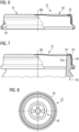
- zeigt eine Seitenansicht eines Press-on Twist-off-Verschlusses 21 (PT-Verschluss) mit einem Dichtungselement 23, teilweise als Schnitt;
- Figur 7
- zeigt eine Seitenansicht des PT-Verschlusses 21 mit dem Dichtungselement 23 auf einem Gefäß 25, teilweise als Schnitt;
- Figur 8
- zeigt eine Draufsicht des PT-Verschlusses 21;
- Figur 9
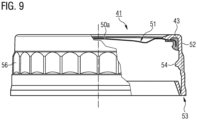
- zeigt eine Seitenansicht eines Composite-Verschlusses 41 (Band-Guard) mit einem Dichtungselement 43, teilweise als Schnitt;
- Figur 10
- zeigt eine Seitenansicht des Composite-Verschlusses 41 (Band-Guard) mit dem Dichtungselement 43 auf einem Gefäß 45, teilweise als Schnitt;
- Figur 11
- zeigt eine Draufsicht des Composite-Verschlusses 41 (Band-Guard);
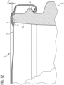
- Figur 12
- zeigt einen vergrößerten Ausschnitt des Nockendrehverschlusses von
Figur 2 . - Die
Figuren 1 und 3 zeigen einen Nockendrehverschluss 1. Der Nockendrehverschluss 1 umfasst einen metallischen Träger 11 und ein Dichtungselement 3. In der Darstellung derFigur 2 ist der Nockendrehverschluss 1 auf ein Gefäß 5 aufgebracht. An dem unteren Ende des Nockendrehverschlusses 1 ist eine Einrollung 9 ausgebildet. Mehrere Nocken 7 sind umfänglich verteilt aus der Einrollung 9 ausgebildet. Nocken 7 sind durch eine axiale Verformung der Einrollung 9 geformt und erstrecken sich radial weiter zur Mitte des Nockendrehverschlusses 1 als die Einrollung 9. Der in denFiguren 1 bis 3 abgebildete Nockendrehverschluss 1 umfasst vier Nocken 7, die umfänglich gleichmäßig verteilt ausgebildet sind. Die Schnitte, die in denFiguren 1 und 2 teilweise abgebildet sind, entsprechen dem Schnitt III-III inFigur 3 . - Nahe dem radial äußeren Endabschnitt des Nockendrehverschlusses 1 ist ein Kanal 2 in dem oberen Abschnitt 10 des Trägers 11 ausgebildet. Das Dichtungselement 3 ist zumindest teilweise in dem Kanal 2 angeordnet. In dieser Ausführungsform ist das Dichtungselement 3 ringförmig ausgestaltet, in anderen Ausführungsformen kann das Dichtungselement 3 scheibenförmig ausgestaltet sein, dies insbesondere wenn der Durchmesser des Nockendrehverschlusses klein (z.B. maximal 30 mm) ist.
- Zur Haftvermittlung zwischen dem metallischen Träger 11 und dem Dichtungselement 3 ist typischerweise ein Haftlack auf die Seite des metallischen Trägers 11 aufgebracht, die mit dem Dichtungselement 3 in Kontakt steht.
- In
Figur 2 ist der Nockendrehverschluss 1 auf ein Gefäß 5 aufgebracht. Das Gefäß 5 umfasst eine Gefäßmündung 5a als oberen Abschnitt des Gefäßes 5. Die Gefäßmündung umfasst ein Gewinde 6 und ein oberes Ende 4 der Gefäßmündung 5a. Das Gewinde 6 ist umlaufend im Bereich der Gefäßmündung 5a ausgebildet und erstreckt sich umlaufend aufwärts oder abwärts (in Abhängigkeit des Blickwinkels). - Zum Aufbringen des Nockendrehverschlusses 1 auf ein Gefäß 5 werden Nocken 7 mit Abschnitten des Gewindes 6 in Kontakt gebracht und der Nockendrehverschluss 1 im Uhrzeigersinn relativ zum Gefäß 5 gedreht. Durch die Ausgestaltung des Gewindes 6 und die Interaktion der Nocken 7 mit dem Gewinde 6 bewegt sich das obere Ende 4 der Gefäßmündung 5a in Richtung des Dichtungselements 3 während der Drehbewegung des Nockendrehverschlusses 1 relativ zu dem Gefäß 5. Durch eine weitere Drehbewegung des Nockendrehverschlusses 1 drückt das obere Ende 4 der Gefäßmündung 5a in das Dichtungselement 3 ein und verformt dieses, sodass ein Abschnitt des oberen Endes 4 der Gefäßmündung 5a von dem Dichtungselement 3 bedeckt ist, wodurch das Gefäß 5 dicht verschlossen ist. Ein dichter Verschluss des Gefäßes 5 ist insbesondere notwendig, um einem erhöhten Druck während einer thermischen Behandlung des verschlossenen Gefäßes 5 bei Temperaturen oberhalb von 70 °C, 90 °C oder sogar oberhalb von 120 °C Stand zu halten.
- Der Nockendrehverschluss 1, wie in den
Figuren 1 bis 3 abgebildet, umfasst einen Safety Button 10b, der in dem oberen Abschnitt 10 des Trägers 11 ausgebildet ist. Aufgrund der Steigung 10a in dem oberen Abschnitt 10 des Trägers 11 klappt der Safety Button 10b in Richtung der Mitte des Gefäßes, wenn ein ausreichend großer Unterdruck in dem Gefäß vorliegt. Ein solches Vakuum kann durch das Einbringen von Wasserdampf in das Gefäß vor dem Verschließen des Gefäßes mit dem Verschluss erzeugt werden. - Öffnet ein Verbraucher das Gefäß, indem der Gefäßverschluss entfernt wird, steigt der Druck in dem Gefäß auf Umgebungsdruck und der Safety Button 10b klappt von der Mitte des Gefäßes weg. Das Umklappen des Safety Buttons 10b wird von einem charakteristischen Geräusch begleitet, durch das ein Verbraucher erkennen kann, dass vor dem Öffnen des Gefäßes ein Vakuum in dem Gefäß geherrscht hat.
- Die
Figuren 4 und 5 zeigen einen Composite-Verschluss 61 (Combi-Twist), der analog zu dem beschriebenen Nockendrehverschluss 1 durch eine Drehbewegung auf ein Gefäß aufgebracht werden kann und durch eine Drehbewegung von dem Gefäß entfernt werden kann. - Der Composite-Verschluss 61 umfasst einen Träger mit einem oberen metallischen Abschnitt 71 und einem Kunststoff-Abschnitt 72, der L-förmig geformt ist. Nahe dem radialen Ende des metallischen Abschnitts 71 des Trägers ist ein Kanal 78 geformt und eine Rollung 77 ist am radialen Ende des metallischen Abschnitts 71 ausgebildet. Ein Dichtungselement ist zumindest teilweise in dem Kanal 78 angeordnet.
- Mehrere, auf der Innenseite des Kunststoff-Abschnitts 72 gebildete Gewindeelemente 74a, 74b kontaktieren mit einem Gegengewinde im Bereich der Mündung eines Gefäßes (nicht dargestellt), auf das der Composite-Verschluss 61 aufgebracht werden soll. Der Kunststoff-Abschnitt 72 des Composite-Verschlusses 61 umfasst weiterhin eine Originalitätssicherung 73, die ähnlich der Originalitätssicherung wie in den
Figuren 9 bis 11 ausgestaltet ist und mit Blick auf dieFiguren 9 bis 11 näher beschrieben wird. - Wird der Composite-Verschluss 61 auf ein Gefäß durch eine Drehbewegung aufgeschraubt, ergibt sich eine analoge Interaktion der Gefäßmündung des Gefäßes mit dem Dichtungselement des Composite-Verschlusses 61 wie anhand des Nockendrehverschlusses 1 beschrieben.
- In den
Figuren 6 bis 8 ist ein Press-on Twist-Off-Verschluss 21 (PT-Verschluss) abgebildet. Der PT-Verschluss 21 umfasst einen metallischen Träger 31 mit einer Einrollung 29 am unteren Ende des Trägers 31 und einem Safety Button 30a in dem oberen Abschnitt 30 des Trägers 31. - Ein Dichtungselement 23 ist sowohl im Bereich des oberen Abschnitts 30 des Trägers 31 als auch in erheblichem Umfang auf der Schürze des Trägers, die sich ausgehend von dem oberen Abschnitt 30 des Trägers 31 nach unten erstreckt, ausgebildet. Der PT-Verschluss 21 wird im Gegensatz zu dem Nockendrehverschluss 1 und dem Composite-Verschluss 61 bei einem Aufbringen auf ein Gefäß 25, auf die Gefäßmündung 25a aufgepresst. Während des Aufpressens auf die Gefäßmündung 25a ist das Dichtungselement 23 ausreichend weich, um Gewindeelemente 26 der Gefäßmündung 25a elastisch zu umschließen. Typischerweise wird hierfür das Dichtungselement 23 vor dem Aufbringen des PT-Verschlusses 21 auf ein Gefäß 5 mit Wasserdampf behandelt, um die nötige Weichheit des Dichtungselements 23 zu verursachen. Nach Abkühlung des Dichtungselements 23 ist ein Gegengewinde in Form eines Negativs der Gewindeelemente 26 der Gefäßmündung in dem Dichtungselement 23 gebildet.
- Ein oberes Ende 24 der Gefäßmündung 25a kontaktiert das Dichtungselement 23.
- Zum Öffnen des Gefäßes 25, wird der PT-Verschluss 21 durch eine Drehbewegung von dem Gefäß 25 entfernt.
-
Figuren 9 bis 11 zeigen einen Composite-Verschluss 41 (Band-Guard), der analog zu dem beschriebenen PT-Verschluss 21 funktionsfähig ist. - Der Composite-Verschluss 41 umfasst einen Träger mit einem metallischen Abschnitt 51 und einem Kunststoff-Abschnitt 52, eine Originalitätssicherung 53 und einen Safety Button 50a. Die Originalitätssicherung 53 ist so ausgestaltet, dass diese von dem übrigen Composite-Verschluss 41 entfernt wird, wenn der Composite-Verschluss 41 von einem Gefäß 45 entfernt wird, und dient der Überprüfbarkeit eines Verbrauchers, ob der Composite-Verschluss 41 bereits von dem Gefäß 45 entfernt wurde. Der Safety Button 50a ist analog zu dem Safety Button 10b des Nockendrehverschlusses 1 ausgestaltet und funktionsfähig.
- Der Kunststoff-Abschnitt des Composite-Verschluss 41 kann mehrere axial verlaufende Einbuchtungen 56 umfassen, um die Stabilität des Verschlusses zu erhöhen.
- Ein Dichtungselement 43 ist so in dem Composite-Verschluss 41 angeordnet, dass dieses sowohl den metallischen Abschnitt 51 als auch den Kunststoff-Abschnitt 52 kontaktiert. Zum Verschließen eines Gefäßes 45 wird der Composite-Verschluss 41 auf die Gefäßmündung 45a des Gefäßes 45 aufgepresst, sodass zumindest das obere Ende 44 der Gefäßmündung 45a das Dichtungselement 43 kontaktiert.
- Der Kunststoff-Abschnitt 52 des Trägers umfasst mehrere versetzte Vorsprünge 54, die mit Gewindeelementen 46 der Gefäßmündung 45a interagieren. Zum Öffnen eines Gefäßes 45, das mit dem Composite-Verschluss 41 verschlossen ist, kann der Composite-Verschluss 41 relativ zu dem Gefäß 45 verdreht werden.
- Der Abstand h3 eines Dichtungselements 3 zwischen einem oberen Ende 4 einer Gefäßmündung 5a eines Gefäßes 5 und der unteren Seite eines Trägers 11 des Verschlusses 1 ist in
Figur 12 mit Blick auf einen Nockendrehverschluss 1 dargestellt und hier beschrieben. Analog ist der Abstand (Höhe) h3 für andere Verschluss-Typen zu bestimmen. - Das zwischen der Gefäßmündung 5 und dem Träger 11 des Gefäßverschlusses 1 eingeklemmte Dichtungselement 3 besitzt eine Höhe h3, die gegeben ist, wenn ein Gefäß 5 mit dem Verschluss 1 verschlossen ist. Ist die Höhe h3 zu gering droht eine Durchschneidung des Dichtungselements 3, wodurch die Dichtigkeit des verschlossenen Gefäßes 5 beeinträchtigt sein kann. Ist die Höhe h3 zu groß, ist die Dichtigkeit des verschlossenen Gefäßes beeinträchtigt, da die Kontaktfläche zwischen dem oberen Ende 4 der Gefäßmündung 5a und dem Dichtungselement 3 nicht ausreichend groß ist. Um einen passenden Eindruck des oberen Endes 4 der Gefäßmündung 5a in das Dichtungselement zu erreichen, ist die Zusammensetzung des Dichtungselements 3 maßgebend.
- Beispiele von Polymerzusammensetzungen für Dichtungselemente in einem Gefäßverschluss sind in den Tabellen 1 und 2 dargestellt.
Tabelle 1 Beispiel 1 Beispiel 2 Beispiel 3 Beispiel 4 Komponente Buten-Propylen-Copolymer, Gew.-% 94,9 47,5 12,0 12,0 Buten-Ethylen-Copolymer, Gew.-% 47,4 59,9 59,9 LDPE, Gew.-% 23,0 HDPE, Gew.-% 23,0 random-Propylen-Ethylen-Copolymer, Gew.-% Homo-Polybuten, Gew.-% Additive, Gew.-% 5,1 5,1 5,1 5,1 Eigenschaften Reibungskoeffizient, dimensionslos 0,32 0,26 0,23 0,17 Gesamtmigration, mg cm-2 0,56 0,79 0,88 0,83 Sauerstoffdurchlässigkeitsrate, cm3 m-2 d-1 bar-1 370 364 409 307 Tabelle 2 Beispiel 5 Beispiel 6 Beispiel 7 Komponente Buten-Propylen-Copolymer, Gew.-% 12,0 12,0 12,0 Buten-Ethylen-Copolymer, Gew.-% 59,9 59,9 59,9 LDPE, Gew.-% 7,0 HDPE, Gew.-% random-Propylen-Ethylen-Copolymer, Gew.-% 23,0 16,0 Homo-Polybuten, Gew.-% 23,0 Additive, Gew.-% 5,1 5,1 5,1 Eigenschaften Reibungskoeffizient, dimensionslos 0,19 0,20 0,17 Gesamtmigration, mg cm-2 1,05 0,81 0,96 Sauerstoffdurchlässigkeitsrate, cm3 m-2 d-1 bar-1 413 325 368 - Das Buten-Propylen-Copolymer besitzt eine Schmelztemperatur von 114 °C, bestimmt nach ISO 11357-3.
- Ein typischer Wert der Sauerstoffdurchlässigkeitsrate von PVC-haltigen Zusammensetzungen, die als Dichtungselement in Gefäßverschlüssen eingesetzt werden, liegt bei etwa 220 cm3 m-2 d-1 bar-1.
- Die Sauerstoffdurchlässigkeitsraten von bekannten, kommerziell erhältlichen PVC-freien Zusammensetzungen in Gefäßverschlüssen betragen typischerweise 650 cm3 m-2 d-1 bar-1 und mehr. Diesen bekannten Zusammensetzungen werden oft Sauerstoff-Scavenger beigefügt, um das Vorhandensein von Sauerstoff in einem Gefäß, das mit einem solchen Gefäßverschluss verschlossen ist, zu reduzieren.
- Die hierin offenbarten PVC-freien Polymerzusammensetzungen zeigen Sauerstoffdurchlässigkeitsraten, die nahe an den Raten von PVC-haltigen Zusammensetzungen liegen. Die Sauerstoffdurchlässigkeitsraten der hierin offenbarten Zusammensetzung liegen deutlich unterhalb der Sauerstoffdurchlässigkeitsraten von bekannten PVC-freien Zusammensetzungen.
- Durch eine Polymerzusammensetzung mit einer niedrigen Sauerstoffdurchlässigkeitsrate lässt sich der Einsatz von Sauerstoff-Scavenger-Materialien in der Polymerzusammensetzung vermeiden und gleichzeitig wird ein geringer Eintritt von Sauerstoff in das befüllte Gefäß gewährleistet.
- Das Buten-Propylen-Copolymer ist beispielsweise von LyondellBasell erhältlich.
- Das eingesetzte Buten-Ethylen-Copolymer ist beispielsweise von LyondellBasell erhältlich. Der copolymerisierte Buten-Anteil kann bei mindestens 80 mol.-% liegen.
- LDPE und HDPE sind von diversen Anbietern kommerziell erhältlich.
- Das random-Propylen-Ethylen-Copolymer kann von Borealis bezogen werden.
- Homo-Polybuten ist erhältlich von LyondellBasell.
- SEBS ist von Kraton erhältlich, beispielsweise aus der Kraton G-Serie.
Claims (15)
- Gefäßverschluss (1, 21, 41, 61) mit einem Dichtungselement (3, 23, 43, 63), wobei(a) das Dichtungselement (3, 23, 43, 63) eine Polymerzusammensetzung umfasst; und(b) die Polymerzusammensetzung ein Buten-Copolymer umfasst, wobei das Buten-Copolymer eine Schmelztemperatur Tm zwischen 30 °C und 130 °C aufweist, wobei die Schmelztemperatur Tm durch die zweite Aufheizkurve einer DSC-Messung bei einer Heizrate von 10 °C min-1 bestimmt wird.
- Gefäßverschluss nach Anspruch 1, wobei die Schmelztemperatur Tm des Buten-Copolymers zwischen 40 °C und 125 °C, insbesondere zwischen 80 °C und 125 °C, liegt; und/oderwobei Propylen ein Comonomer des Buten-Copolymers ist; und/oderwobei das Buten-Copolymer zwischen 0,1 Gew.-% und 80 Gew.-%, bevorzugt zwischen 5 Gew.-% und 60 Gew.-%, besonders bevorzugt zwischen 8 Gew.-% und 55 Gew.-%, in der Polymerzusammensetzung enthalten ist.
- Gefäßverschluss nach einem der Ansprüche 1 oder 2, wobei die Polymerzusammensetzung ein weiteres Buten-Copolymer umfasst, wobei die Buten-Copolymere unterschiedliche Polymerarten sind,insbesondere wobei ein Comonomer des weiteren Buten-Copolymers Ethylen ist; und/oderwobei das weitere Buten-Copolymer ein Buten-Bipolymer ist; und/oderwobei das weiteren Buten-Copolymer zwischen 10 Gew.-% und 80 Gew.-%, bevorzugt zwischen 22 Gew.-% und 70 Gew.-%, besonders bevorzugt zwischen 40 Gew.-% und 65 Gew.-%, in der Polymerzusammensetzung enthalten ist.
- Gefäßverschluss nach einem der Ansprüche 1 bis 3, wobei die Polymerzusammensetzung ein Polyethylen umfasst,bevorzugt wobei das Polyethylen ein Homo-Polyethylen, insbesondere ein LDPE oder ein HDPE, ist; und/oderwobei das Polyethylen zwischen 5 Gew.-% und 60 Gew.-%, bevorzugt zwischen 10 Gew.-% und 45 Gew.-%, besonders bevorzugt zwischen 15 Gew.-% und 35 Gew.-%, in der Polymerzusammensetzung enthalten ist.
- Gefäßverschluss nach einem der Ansprüche 1 bis 3, wobei die Polymerzusammensetzung ein random-Propylen-Copolymer umfasst,insbesondere wobei Ethylen ein Comonomer des random-Propylen-Copolymers ist; und/oderwobei das random-Propylen-Copolymer ein Bipolymer ist; und/oderwobei das random-Propylen-Copolymer zwischen 5 Gew.-% und 60 Gew.-%, bevorzugt zwischen 10 Gew.-% und 45 Gew.-%, besonders bevorzugt zwischen 15 Gew.-% und 35 Gew.-%, in der Polymerzusammensetzung enthalten ist.
- Gefäßverschluss nach einem der Ansprüche 1 bis 3, wobei die Polymerzusammensetzung ein Buten-Homopolymer umfasst,
insbesondere wobei das Buten-Homopolymer zwischen 5 Gew.-% und 60 Gew.-%, bevorzugt zwischen 10 Gew.-% und 45 Gew.-%, besonders bevorzugt zwischen 15 Gew.-% und 35 Gew.-%, in der Polymerzusammensetzung enthalten ist. - Gefäßverschluss nach einem der Ansprüche 1 oder 2, wobei die Polymerzusammensetzung ein Copolymer enthält, das Styrol als ein Comonomer umfasst,bevorzugt wobei das Copolymer, das Styrol als ein Comonomer umfasst, ein SBS, SEPS, SEEPS oder SEBS ist, insbesondere ein SEBS ist; und/oderwobei das Copolymer, das Styrol als ein Comonomer umfasst, zwischen 10 Gew.-% und 70 Gew.-%, bevorzugt zwischen 20 Gew.-% und 60 Gew.-%, besonders bevorzugt zwischen 35 Gew.-% und 55 Gew.-%, in der Polymerzusammensetzung enthalten ist.
- Gefäßverschluss nach Anspruch 7, wobei die Polymerzusammensetzung ein Buten-Homopolymer umfasst,
insbesondere wobei das Buten-Homopolymer zwischen 5 Gew.-% und 60 Gew.-%, bevorzugt zwischen 10 Gew.-% und 45 Gew.-%, besonders bevorzugt zwischen 15 Gew.-% und 35 Gew.-%, in der Polymerzusammensetzung enthalten ist. - Gefäßverschluss nach einem der Ansprüche 1 oder 2, wobei das Buten-Copolymer zu mindestens 80 Gew.-%, bevorzugt mindestens 90 Gew.-%, in der Polymerzusammensetzung enthalten ist.
- Gefäßverschluss nach einem der vorhergehenden Ansprüche, wobei die Polymerzusammensetzung maximal 10 Gew.-% Homo-Polypropylen, bevorzugt kein Homo-Polypropylen, umfasst.
- Gefäßverschluss nach einem der vorhergehenden Ansprüche, wobei die Polymerzusammensetzung maximal 10 Gew.-%, bevorzugt maximal 5 Gew.-%, einer bei 20 °C und 1000 hPa flüssigen Komponente umfasst, besonders bevorzugt die Polymerzusammensetzung keine bei 20 °C und 1000 hPa flüssige Komponente umfasst.
- Gefäßverschluss nach einem der vorhergehenden Ansprüche, wobei die Polymerzusammensetzung einen statischen Reibungskoeffizienten, bestimmt nach DIN EN ISO 8295, von maximal 0,50, bevorzugt von maximal 0,40, aufweist; und/oderwobei die Polymerzusammensetzung eine Sauerstoffdurchlässigkeitsrate, bestimmt nach DIN 53380, von weniger als 500 cm3 m-2 d-1 bar-1, bevorzugt von weniger als 400 cm3 m-2 d-1 bar-1, aufweist; und/oderwobei die Polymerzusammensetzung eine Gesamtmigration, bestimmt nach DIN-EN 1186-14, von maximal 1,20 mg cm-2, bevorzugt von maximal 1,0 mg cm-2, besonders bevorzugt von maximal 0,8 mg cm-2, aufweist.
- Gefäßverschluss nach einem der vorhergehenden Ansprüche, wobei der Gefäßverschluss (1, 21, 41, 61) ein Schraubverschluss, insbesondere ein Nockendrehverschluss (1), ein Press-on-Twist-off-Verschluss (21) oder ein Composite-Verschluss (41, 61) ist.
- Gefäß (5, 25, 45) mit einer Gefäßmündung (5a, 25a, 45a) und einer verschließbaren Öffnung am Ende der Gefäßmündung, wobei die Öffnung mit einem Gefäßverschluss (1, 21, 41, 61) nach einem der Ansprüche 1 bis 13 verschlossen ist.
- Verfahren zur Herstellung eines verschlossenen und befüllten Gefäßes, mit den Schritten:(a) Bereitstellen eines Gefäßes (1, 21, 41, 61) mit einer Gefäßmündung (5a, 25a, 45a) und einer verschließbaren Öffnung am Ende der Gefäßmündung;(b) Befüllen des Gefäßes mit einem Lebensmittel durch die Öffnung des Gefäßes;(c) Verschließen der Öffnung des Gefäßes mit einem Gefäßverschluss nach einem der Ansprüche 1 bis 13.
Applications Claiming Priority (3)
| Application Number | Priority Date | Filing Date | Title |
|---|---|---|---|
| DE102018117766 | 2018-07-23 | ||
| DE102018128283.4A DE102018128283B4 (de) | 2018-07-23 | 2018-11-12 | Gefäßverschluss mit Dichtungselement |
| PCT/IB2019/054106 WO2020021348A1 (de) | 2018-07-23 | 2019-05-17 | Gefaessverschluss mit dichtungselement |
Publications (2)
| Publication Number | Publication Date |
|---|---|
| EP3826936A1 EP3826936A1 (de) | 2021-06-02 |
| EP3826936B1 true EP3826936B1 (de) | 2024-07-17 |
Family
ID=69147802
Family Applications (1)
| Application Number | Title | Priority Date | Filing Date |
|---|---|---|---|
| EP19736490.4A Active EP3826936B1 (de) | 2018-07-23 | 2019-05-17 | Gefaessverschluss mit dichtungselement |
Country Status (7)
| Country | Link |
|---|---|
| US (2) | US12589924B2 (de) |
| EP (1) | EP3826936B1 (de) |
| CN (1) | CN112437744B (de) |
| DE (2) | DE102018128283B4 (de) |
| ES (1) | ES2985372T3 (de) |
| PL (1) | PL3826936T3 (de) |
| WO (1) | WO2020021348A1 (de) |
Families Citing this family (6)
| Publication number | Priority date | Publication date | Assignee | Title |
|---|---|---|---|---|
| DE102018128283B4 (de) | 2018-07-23 | 2023-04-27 | Silgan White Cap Manufacturing Gmbh | Gefäßverschluss mit Dichtungselement |
| DE102019124760B4 (de) | 2019-06-11 | 2026-01-08 | Silgan White Cap Manufacturing Gmbh | Gefäßverschluß mit Dichtungselement |
| DE102019132561A1 (de) * | 2019-11-29 | 2021-06-02 | Silgan White Cap Manufacturing Gmbh | Geschäumtes Dichtungselement und Gefäßverschluss mit dem geschäumten Dichtungselement |
| EP4522684A1 (de) * | 2022-12-20 | 2025-03-19 | ACTEGA DS GmbH | Gefässverschlüsse mit nur einem polymer |
| EP4662277A1 (de) | 2023-02-07 | 2025-12-17 | ACTEGA DS GmbH | Gefässverschluss mit dichtungselement |
| WO2025057033A1 (de) * | 2023-09-12 | 2025-03-20 | Silgan Holdings Inc. | GEFÄßVERSCHLUSS MIT DICHTUNGSELEMENT, GEFÄß MIT GEFÄßVERSCHLUSS UND VERFAHREN ZUR HERSTELLUNG EINES VERSCHLOSSENEN GEFÄßES |
Family Cites Families (53)
| Publication number | Priority date | Publication date | Assignee | Title |
|---|---|---|---|---|
| JPS5296183A (en) * | 1976-02-09 | 1977-08-12 | Mitsui Petrochemical Ind | Method of producing vessel lid |
| JPS54154694A (en) * | 1978-05-26 | 1979-12-05 | Toyo Seikan Kaisha Ltd | Metal stopper and making method thereof |
| JPS54155253A (en) * | 1978-05-30 | 1979-12-07 | Mitsui Petrochem Ind Ltd | Gasket for bottle cap |
| JPS54158456A (en) * | 1978-06-05 | 1979-12-14 | Mitsui Petrochem Ind Ltd | Packing material of bottle stopper |
| US4726999A (en) * | 1984-10-31 | 1988-02-23 | Shell Oil Company | Laminated structure comprising a substrate layer composed of a crystalline propylene resin and a heat-sealable layer composed of a crystalline propylene random copolymer composition |
| CA1300788C (en) * | 1984-11-02 | 1992-05-12 | Mitsui Chemicals, Incorporated | Crystalline random propylene copolymer composition and composite laminate comprising said composition |
| US4677025A (en) * | 1985-08-30 | 1987-06-30 | Shell Oil Company | Unique molecular weight distribution polybutylene blend and film |
| KR100197327B1 (ko) | 1988-07-15 | 1999-06-15 | 치어즈 엠. 노우드 | 신디오택틱 폴리프로필렌 |
| US4863030A (en) * | 1988-08-01 | 1989-09-05 | Anchor Hocking Corporation | Press-on, twist-off plastisol-lined metal closure |
| JPH04339772A (ja) * | 1991-05-09 | 1992-11-26 | Toyo Seikan Kaisha Ltd | ライナー付容器蓋及びその製造方法 |
| US5929128A (en) * | 1993-08-18 | 1999-07-27 | The Dow Chemical Company | Gaskets made from olefin polymers |
| JP3302178B2 (ja) * | 1994-06-22 | 2002-07-15 | 日本クラウンコルク株式会社 | 合成樹脂製容器蓋 |
| US5626929A (en) * | 1995-06-07 | 1997-05-06 | Aluminum Company Of America | Peelable and heat sealable lidstock material for plastic containers |
| US7182986B1 (en) * | 1998-07-09 | 2007-02-27 | Kuraray Co., Ltd. | Container cap |
| CN100400613C (zh) * | 1998-12-24 | 2008-07-09 | 蒙特尔技术有限公司 | 由聚烯烃制备的瓶盖 |
| US6677397B1 (en) * | 2000-08-14 | 2004-01-13 | White Cap, Inc. | Closure cap liners having oxygen barrier properties |
| US6930160B2 (en) * | 2000-08-22 | 2005-08-16 | Idemitsu Petrochemical Co. Ltd. | 1-Butene polymer and molded product consisting of the polymer |
| CA2389307C (en) * | 2000-09-01 | 2008-12-30 | Kuraray Co., Ltd. | Resin composition and multilayered container |
| FI20002884L (fi) | 2000-10-12 | 2002-04-13 | Duraban Oy | Elastomeerien polyalfaolefiinipehmittimet |
| US6630237B2 (en) * | 2001-02-05 | 2003-10-07 | Cryovac, Inc. | Peelably sealed packaging |
| US7056971B2 (en) * | 2001-02-13 | 2006-06-06 | Gls Corporation | Essentially gas-impermeable thermoplastic elastomer |
| US7652092B2 (en) | 2002-08-12 | 2010-01-26 | Exxonmobil Chemical Patents Inc. | Articles from plasticized thermoplastic polyolefin compositions |
| US7622523B2 (en) * | 2002-08-12 | 2009-11-24 | Exxonmobil Chemical Patents Inc. | Plasticized polyolefin compositions |
| JP4076851B2 (ja) * | 2002-12-25 | 2008-04-16 | 住友化学株式会社 | オレフィン系樹脂組成物の製造方法 |
| JP2005105105A (ja) * | 2003-09-30 | 2005-04-21 | Sumitomo Chemical Co Ltd | 樹脂組成物ペレット |
| CN101065438B (zh) * | 2004-11-25 | 2012-06-06 | 三井化学株式会社 | 丙烯系树脂组合物及其用途 |
| AU2006237514B2 (en) * | 2005-03-17 | 2011-10-27 | Dow Global Technologies Llc | Cap liners, closures and gaskets from multi-block polymers |
| GB0511320D0 (en) | 2005-06-03 | 2005-07-13 | Exxonmobil Chem Patents Inc | Elastomeric structures |
| JP5300083B2 (ja) | 2006-04-19 | 2013-09-25 | エクソンモービル・ケミカル・パテンツ・インク | 熱可塑性ポリオレフィン組成物からなる製品 |
| JP5377307B2 (ja) * | 2006-08-08 | 2013-12-25 | バーゼル・ポリオレフィン・イタリア・ソチエタ・ア・レスポンサビリタ・リミタータ | ブテン−1コポリマー |
| WO2008025710A1 (en) * | 2006-08-30 | 2008-03-06 | Basell Polyolefine Gmbh | 1-butene propylene copolymer compositions |
| EP1947143A1 (de) * | 2007-01-19 | 2008-07-23 | Borealis Technology Oy | Polypropylen-Harzzusammensetzung und daraus hergestellter Formkörper |
| EP2058379A1 (de) | 2007-11-09 | 2009-05-13 | ACTEGA DS GmbH | Verfahren zur Herstellung eines Gefässverschlusses |
| US8052822B2 (en) * | 2008-02-15 | 2011-11-08 | Exxonmobil Chemical Patents Inc. | Blends of low crystallinity, low molecular weight propylene copolymers and styrenic block copolymers |
| KR101588911B1 (ko) * | 2008-03-13 | 2016-01-26 | 바셀 폴리올레핀 이탈리아 에스.알.엘 | 1-부텐 삼원중합체 |
| KR101719843B1 (ko) * | 2009-07-24 | 2017-03-24 | 다우 글로벌 테크놀로지스 엘엘씨 | 코팅된 용기 장치, 그의 제조 방법 |
| US8592013B2 (en) * | 2009-07-24 | 2013-11-26 | Dow Global Technologies, Llc. | Coated container device, method of making the same |
| EP2501756B1 (de) * | 2009-11-17 | 2017-01-25 | Basell Poliolefine Italia S.r.l. | Weiche polyolefinzusammensetzungen mit verbesserter verarbeitbarkeit |
| KR101751890B1 (ko) * | 2011-05-11 | 2017-06-28 | 악테가 데에스 게엠베하 | Pvc-무함유 마개 |
| US9688451B2 (en) * | 2012-02-15 | 2017-06-27 | Silgan White Cap LLC | Composite closure with seal indicating panel |
| EP2631271A1 (de) * | 2012-02-24 | 2013-08-28 | Basell Poliolefine Italia S.r.l. | 1-Buten-Copolymerzusammensetzungen für extrudierte Profile |
| JP5929633B2 (ja) * | 2012-08-30 | 2016-06-08 | 日本ポリプロ株式会社 | ポリプロピレン系樹脂成形体および樹脂成形体の製造方法 |
| MX2014008464A (es) | 2014-07-10 | 2016-01-11 | Indelpro S A De C V | Una composicion mejorada a base de un homopolimero y/o copolimero de polipropileno para fabricar y/o elaborar tapas de bebidas carbonatadas con caracteristicas incrementadas de rigidez y hermeticidad sin la necesidad de usar sellos y proceso de fabricacion. |
| US10214640B2 (en) * | 2014-12-19 | 2019-02-26 | Basell Poliolefine Italia S.R.L. | Soft and flexible polyolefin composition |
| KR101890545B1 (ko) | 2015-05-26 | 2018-08-21 | 바셀 폴리올레핀 이탈리아 에스.알.엘 | 클로져용 폴리올레핀 개스킷 |
| EP3334782B1 (de) | 2015-08-10 | 2019-05-08 | SABIC Global Technologies B.V. | Zusammensetzung mit heterophasischem propylencopolymer |
| WO2017162817A1 (en) * | 2016-03-24 | 2017-09-28 | Basell Poliolefine Italia S.R.L. | Soft polyolefin composition |
| WO2018108228A1 (de) * | 2016-12-13 | 2018-06-21 | Actega Ds Gmbh | Thermoplastische vulkanisate |
| EP3661971B1 (de) * | 2017-08-04 | 2024-04-10 | Basell Poliolefine Italia S.r.l. | Buten-1-polymer-zusammensetzung mit hoher schmelzflussrate |
| CN110891984A (zh) * | 2017-08-04 | 2020-03-17 | 巴塞尔聚烯烃意大利有限公司 | 具有高熔体流动速率的丁烯-1聚合物 |
| WO2019025582A1 (en) * | 2017-08-04 | 2019-02-07 | Basell Poliolefine Italia S.R.L. | BUTENE-1 POLYMER WITH HIGH FLUIDITY INDEX |
| DE102018113157B4 (de) | 2018-06-01 | 2022-03-03 | Silgan White Cap Manufacturing Gmbh | Gefäßverschluss mit Dichtungselement |
| DE102018128283B4 (de) | 2018-07-23 | 2023-04-27 | Silgan White Cap Manufacturing Gmbh | Gefäßverschluss mit Dichtungselement |
-
2018
- 2018-11-12 DE DE102018128283.4A patent/DE102018128283B4/de not_active Expired - Fee Related
- 2018-11-12 DE DE202018006974.4U patent/DE202018006974U1/de active Active
-
2019
- 2019-05-17 US US17/262,328 patent/US12589924B2/en active Active
- 2019-05-17 WO PCT/IB2019/054106 patent/WO2020021348A1/de not_active Ceased
- 2019-05-17 PL PL19736490.4T patent/PL3826936T3/pl unknown
- 2019-05-17 ES ES19736490T patent/ES2985372T3/es active Active
- 2019-05-17 CN CN201980046428.0A patent/CN112437744B/zh active Active
- 2019-05-17 EP EP19736490.4A patent/EP3826936B1/de active Active
-
2025
- 2025-12-01 US US19/404,271 patent/US20260084872A1/en active Pending
Also Published As
| Publication number | Publication date |
|---|---|
| CN112437744A (zh) | 2021-03-02 |
| PL3826936T3 (pl) | 2024-10-28 |
| EP3826936A1 (de) | 2021-06-02 |
| CN112437744B (zh) | 2023-10-31 |
| DE102018128283A1 (de) | 2020-01-23 |
| WO2020021348A1 (de) | 2020-01-30 |
| ES2985372T3 (es) | 2024-11-05 |
| DE102018128283B4 (de) | 2023-04-27 |
| US20210339919A1 (en) | 2021-11-04 |
| US12589924B2 (en) | 2026-03-31 |
| DE202018006974U1 (de) | 2025-01-23 |
| US20260084872A1 (en) | 2026-03-26 |
Similar Documents
| Publication | Publication Date | Title |
|---|---|---|
| DE102018128283B4 (de) | Gefäßverschluss mit Dichtungselement | |
| DE68904683T2 (de) | Schliessdeckel fuer behaelter und zusammensetzungen zur herstellung der zugehoerigen dichtungsring. | |
| DE3885529T2 (de) | Polymerzusammensetzung und für Verpackungen verwendbare Filme. | |
| EP2470435B2 (de) | Polymercompound für dichtungen bei fetthaltigen füllgütern | |
| EP2918652B1 (de) | VERFAHREN ZUR HERSTELLUNG EINES GEFÄßVERSCHLUSSES | |
| EP3265513B1 (de) | Gefässverschluss aus metall oder kunststoff | |
| EP4065635A1 (de) | Geschaeumtes dichtungselement und gefaessverschluss mit dem geschaeumten dichtungselement | |
| DE102018113157B4 (de) | Gefäßverschluss mit Dichtungselement | |
| EP0503124B1 (de) | Gefässverschluss mit einem Dichtungselement aus einem Polymercompound | |
| EP4061657B1 (de) | Gefaessverschluss mit dichtungselement | |
| WO2021115571A1 (de) | Vakuum-gefässdrehverschluss mit gefässverschlussdichtung | |
| DE102019124760B4 (de) | Gefäßverschluß mit Dichtungselement | |
| DE69319061T2 (de) | Wärmeschrumpfbarer Verbundfilm, Verfahren zu seiner Herstellung und Verwendung für Verpackungen | |
| DE202018006892U1 (de) | Gefäßverschluss mit Dichtungselement | |
| EP4680672A1 (de) | DICHTUNGSMATERIAL FÜR GEFÄßVERSCHLÜSSE BASIEREND AUF BUTEN -(CO)POLYMEREN | |
| EP4328267A1 (de) | Gefässverschluss mit dichtungselement, gefäss mit gefässverschluss und verfahren zur herstellung eines verschlossenen gefässes | |
| DE602004011030T2 (de) | Transparente verschlusskappenauskleidung mit sauerstoffsperreigenschaften | |
| WO2025057034A1 (de) | GEFÄßVERSCHLUSS MIT DICHTUNGSELEMENT, GEFÄß MIT GEFÄßVERSCHLUSS UND VERFAHREN ZUR HERSTELLUNG EINES VERSCHLOSSENEN GEFÄßES | |
| WO2025057033A1 (de) | GEFÄßVERSCHLUSS MIT DICHTUNGSELEMENT, GEFÄß MIT GEFÄßVERSCHLUSS UND VERFAHREN ZUR HERSTELLUNG EINES VERSCHLOSSENEN GEFÄßES | |
| EP3350256A1 (de) | Gleitmittelsystem | |
| EP4662277A1 (de) | Gefässverschluss mit dichtungselement | |
| DE202009018714U1 (de) | Polymercompound für Dichtungen bei fetthaltigen Füllgütern | |
| DE9103212U1 (de) | Polymercompound zur Herstellung von Dichtungselementen für Gefäßverschlüsse |
Legal Events
| Date | Code | Title | Description |
|---|---|---|---|
| STAA | Information on the status of an ep patent application or granted ep patent |
Free format text: STATUS: UNKNOWN |
|
| STAA | Information on the status of an ep patent application or granted ep patent |
Free format text: STATUS: THE INTERNATIONAL PUBLICATION HAS BEEN MADE |
|
| PUAI | Public reference made under article 153(3) epc to a published international application that has entered the european phase |
Free format text: ORIGINAL CODE: 0009012 |
|
| STAA | Information on the status of an ep patent application or granted ep patent |
Free format text: STATUS: REQUEST FOR EXAMINATION WAS MADE |
|
| 17P | Request for examination filed |
Effective date: 20210113 |
|
| AK | Designated contracting states |
Kind code of ref document: A1 Designated state(s): AL AT BE BG CH CY CZ DE DK EE ES FI FR GB GR HR HU IE IS IT LI LT LU LV MC MK MT NL NO PL PT RO RS SE SI SK SM TR |
|
| DAV | Request for validation of the european patent (deleted) | ||
| DAX | Request for extension of the european patent (deleted) | ||
| STAA | Information on the status of an ep patent application or granted ep patent |
Free format text: STATUS: EXAMINATION IS IN PROGRESS |
|
| 17Q | First examination report despatched |
Effective date: 20221223 |
|
| GRAP | Despatch of communication of intention to grant a patent |
Free format text: ORIGINAL CODE: EPIDOSNIGR1 |
|
| STAA | Information on the status of an ep patent application or granted ep patent |
Free format text: STATUS: GRANT OF PATENT IS INTENDED |
|
| RIC1 | Information provided on ipc code assigned before grant |
Ipc: C09K 3/10 20060101ALI20240202BHEP Ipc: B65D 53/02 20060101ALI20240202BHEP Ipc: B65D 51/14 20060101ALI20240202BHEP Ipc: C08L 23/20 20060101ALI20240202BHEP Ipc: B65D 53/00 20060101AFI20240202BHEP |
|
| INTG | Intention to grant announced |
Effective date: 20240219 |
|
| GRAS | Grant fee paid |
Free format text: ORIGINAL CODE: EPIDOSNIGR3 |
|
| GRAA | (expected) grant |
Free format text: ORIGINAL CODE: 0009210 |
|
| STAA | Information on the status of an ep patent application or granted ep patent |
Free format text: STATUS: THE PATENT HAS BEEN GRANTED |
|
| AK | Designated contracting states |
Kind code of ref document: B1 Designated state(s): AL AT BE BG CH CY CZ DE DK EE ES FI FR GB GR HR HU IE IS IT LI LT LU LV MC MK MT NL NO PL PT RO RS SE SI SK SM TR |
|
| REG | Reference to a national code |
Ref country code: CH Ref legal event code: EP |
|
| REG | Reference to a national code |
Ref country code: DE Ref legal event code: R096 Ref document number: 502019011708 Country of ref document: DE |
|
| REG | Reference to a national code |
Ref country code: IE Ref legal event code: FG4D Free format text: LANGUAGE OF EP DOCUMENT: GERMAN |
|
| REG | Reference to a national code |
Ref country code: NL Ref legal event code: FP |
|
| REG | Reference to a national code |
Ref country code: SE Ref legal event code: TRGR |
|
| REG | Reference to a national code |
Ref country code: GR Ref legal event code: EP Ref document number: 20240402014 Country of ref document: GR Effective date: 20241007 |
|
| REG | Reference to a national code |
Ref country code: ES Ref legal event code: FG2A Ref document number: 2985372 Country of ref document: ES Kind code of ref document: T3 Effective date: 20241105 |
|
| REG | Reference to a national code |
Ref country code: LT Ref legal event code: MG9D |
|
| PG25 | Lapsed in a contracting state [announced via postgrant information from national office to epo] |
Ref country code: PT Free format text: LAPSE BECAUSE OF FAILURE TO SUBMIT A TRANSLATION OF THE DESCRIPTION OR TO PAY THE FEE WITHIN THE PRESCRIBED TIME-LIMIT Effective date: 20241118 |
|
| PG25 | Lapsed in a contracting state [announced via postgrant information from national office to epo] |
Ref country code: PT Free format text: LAPSE BECAUSE OF FAILURE TO SUBMIT A TRANSLATION OF THE DESCRIPTION OR TO PAY THE FEE WITHIN THE PRESCRIBED TIME-LIMIT Effective date: 20241118 |
|
| PG25 | Lapsed in a contracting state [announced via postgrant information from national office to epo] |
Ref country code: NO Free format text: LAPSE BECAUSE OF FAILURE TO SUBMIT A TRANSLATION OF THE DESCRIPTION OR TO PAY THE FEE WITHIN THE PRESCRIBED TIME-LIMIT Effective date: 20241017 |
|
| PG25 | Lapsed in a contracting state [announced via postgrant information from national office to epo] |
Ref country code: FI Free format text: LAPSE BECAUSE OF FAILURE TO SUBMIT A TRANSLATION OF THE DESCRIPTION OR TO PAY THE FEE WITHIN THE PRESCRIBED TIME-LIMIT Effective date: 20240717 |
|
| PG25 | Lapsed in a contracting state [announced via postgrant information from national office to epo] |
Ref country code: BG Free format text: LAPSE BECAUSE OF FAILURE TO SUBMIT A TRANSLATION OF THE DESCRIPTION OR TO PAY THE FEE WITHIN THE PRESCRIBED TIME-LIMIT Effective date: 20240717 |
|
| PG25 | Lapsed in a contracting state [announced via postgrant information from national office to epo] |
Ref country code: LV Free format text: LAPSE BECAUSE OF FAILURE TO SUBMIT A TRANSLATION OF THE DESCRIPTION OR TO PAY THE FEE WITHIN THE PRESCRIBED TIME-LIMIT Effective date: 20240717 |
|
| PG25 | Lapsed in a contracting state [announced via postgrant information from national office to epo] |
Ref country code: IS Free format text: LAPSE BECAUSE OF FAILURE TO SUBMIT A TRANSLATION OF THE DESCRIPTION OR TO PAY THE FEE WITHIN THE PRESCRIBED TIME-LIMIT Effective date: 20241117 |
|
| PG25 | Lapsed in a contracting state [announced via postgrant information from national office to epo] |
Ref country code: HR Free format text: LAPSE BECAUSE OF FAILURE TO SUBMIT A TRANSLATION OF THE DESCRIPTION OR TO PAY THE FEE WITHIN THE PRESCRIBED TIME-LIMIT Effective date: 20240717 |
|
| PG25 | Lapsed in a contracting state [announced via postgrant information from national office to epo] |
Ref country code: RS Free format text: LAPSE BECAUSE OF FAILURE TO SUBMIT A TRANSLATION OF THE DESCRIPTION OR TO PAY THE FEE WITHIN THE PRESCRIBED TIME-LIMIT Effective date: 20241017 |
|
| PG25 | Lapsed in a contracting state [announced via postgrant information from national office to epo] |
Ref country code: RS Free format text: LAPSE BECAUSE OF FAILURE TO SUBMIT A TRANSLATION OF THE DESCRIPTION OR TO PAY THE FEE WITHIN THE PRESCRIBED TIME-LIMIT Effective date: 20241017 Ref country code: NO Free format text: LAPSE BECAUSE OF FAILURE TO SUBMIT A TRANSLATION OF THE DESCRIPTION OR TO PAY THE FEE WITHIN THE PRESCRIBED TIME-LIMIT Effective date: 20241017 Ref country code: LV Free format text: LAPSE BECAUSE OF FAILURE TO SUBMIT A TRANSLATION OF THE DESCRIPTION OR TO PAY THE FEE WITHIN THE PRESCRIBED TIME-LIMIT Effective date: 20240717 Ref country code: IS Free format text: LAPSE BECAUSE OF FAILURE TO SUBMIT A TRANSLATION OF THE DESCRIPTION OR TO PAY THE FEE WITHIN THE PRESCRIBED TIME-LIMIT Effective date: 20241117 Ref country code: HR Free format text: LAPSE BECAUSE OF FAILURE TO SUBMIT A TRANSLATION OF THE DESCRIPTION OR TO PAY THE FEE WITHIN THE PRESCRIBED TIME-LIMIT Effective date: 20240717 Ref country code: FI Free format text: LAPSE BECAUSE OF FAILURE TO SUBMIT A TRANSLATION OF THE DESCRIPTION OR TO PAY THE FEE WITHIN THE PRESCRIBED TIME-LIMIT Effective date: 20240717 Ref country code: BG Free format text: LAPSE BECAUSE OF FAILURE TO SUBMIT A TRANSLATION OF THE DESCRIPTION OR TO PAY THE FEE WITHIN THE PRESCRIBED TIME-LIMIT Effective date: 20240717 |
|
| PG25 | Lapsed in a contracting state [announced via postgrant information from national office to epo] |
Ref country code: SM Free format text: LAPSE BECAUSE OF FAILURE TO SUBMIT A TRANSLATION OF THE DESCRIPTION OR TO PAY THE FEE WITHIN THE PRESCRIBED TIME-LIMIT Effective date: 20240717 Ref country code: DK Free format text: LAPSE BECAUSE OF FAILURE TO SUBMIT A TRANSLATION OF THE DESCRIPTION OR TO PAY THE FEE WITHIN THE PRESCRIBED TIME-LIMIT Effective date: 20240717 Ref country code: RO Free format text: LAPSE BECAUSE OF FAILURE TO SUBMIT A TRANSLATION OF THE DESCRIPTION OR TO PAY THE FEE WITHIN THE PRESCRIBED TIME-LIMIT Effective date: 20240717 |
|
| REG | Reference to a national code |
Ref country code: DE Ref legal event code: R097 Ref document number: 502019011708 Country of ref document: DE |
|
| PG25 | Lapsed in a contracting state [announced via postgrant information from national office to epo] |
Ref country code: EE Free format text: LAPSE BECAUSE OF FAILURE TO SUBMIT A TRANSLATION OF THE DESCRIPTION OR TO PAY THE FEE WITHIN THE PRESCRIBED TIME-LIMIT Effective date: 20240717 |
|
| PG25 | Lapsed in a contracting state [announced via postgrant information from national office to epo] |
Ref country code: CZ Free format text: LAPSE BECAUSE OF FAILURE TO SUBMIT A TRANSLATION OF THE DESCRIPTION OR TO PAY THE FEE WITHIN THE PRESCRIBED TIME-LIMIT Effective date: 20240717 |
|
| PG25 | Lapsed in a contracting state [announced via postgrant information from national office to epo] |
Ref country code: SK Free format text: LAPSE BECAUSE OF FAILURE TO SUBMIT A TRANSLATION OF THE DESCRIPTION OR TO PAY THE FEE WITHIN THE PRESCRIBED TIME-LIMIT Effective date: 20240717 |
|
| PLBE | No opposition filed within time limit |
Free format text: ORIGINAL CODE: 0009261 |
|
| STAA | Information on the status of an ep patent application or granted ep patent |
Free format text: STATUS: NO OPPOSITION FILED WITHIN TIME LIMIT |
|
| PGFP | Annual fee paid to national office [announced via postgrant information from national office to epo] |
Ref country code: NL Payment date: 20250522 Year of fee payment: 7 |
|
| 26N | No opposition filed |
Effective date: 20250422 |
|
| PGFP | Annual fee paid to national office [announced via postgrant information from national office to epo] |
Ref country code: PL Payment date: 20250505 Year of fee payment: 7 Ref country code: DE Payment date: 20250522 Year of fee payment: 7 |
|
| PGFP | Annual fee paid to national office [announced via postgrant information from national office to epo] |
Ref country code: GB Payment date: 20250522 Year of fee payment: 7 Ref country code: ES Payment date: 20250616 Year of fee payment: 7 |
|
| PGFP | Annual fee paid to national office [announced via postgrant information from national office to epo] |
Ref country code: BE Payment date: 20250520 Year of fee payment: 7 |
|
| PGFP | Annual fee paid to national office [announced via postgrant information from national office to epo] |
Ref country code: FR Payment date: 20250521 Year of fee payment: 7 |
|
| PGFP | Annual fee paid to national office [announced via postgrant information from national office to epo] |
Ref country code: GR Payment date: 20250519 Year of fee payment: 7 |
|
| PGFP | Annual fee paid to national office [announced via postgrant information from national office to epo] |
Ref country code: CH Payment date: 20250601 Year of fee payment: 7 |
|
| PGFP | Annual fee paid to national office [announced via postgrant information from national office to epo] |
Ref country code: AT Payment date: 20250519 Year of fee payment: 7 |
|
| PGFP | Annual fee paid to national office [announced via postgrant information from national office to epo] |
Ref country code: TR Payment date: 20250509 Year of fee payment: 7 |
|
| PGFP | Annual fee paid to national office [announced via postgrant information from national office to epo] |
Ref country code: SE Payment date: 20250522 Year of fee payment: 7 |
|
| PG25 | Lapsed in a contracting state [announced via postgrant information from national office to epo] |
Ref country code: LU Free format text: LAPSE BECAUSE OF NON-PAYMENT OF DUE FEES Effective date: 20250517 |
|
| PG25 | Lapsed in a contracting state [announced via postgrant information from national office to epo] |
Ref country code: MC Free format text: LAPSE BECAUSE OF FAILURE TO SUBMIT A TRANSLATION OF THE DESCRIPTION OR TO PAY THE FEE WITHIN THE PRESCRIBED TIME-LIMIT Effective date: 20240717 |
|
| REG | Reference to a national code |
Ref country code: DE Ref legal event code: R081 Ref document number: 502019011708 Country of ref document: DE Owner name: SILGAN HOLDINGS INC., NORWALK, US Free format text: FORMER OWNER: SILGAN HOLDINGS INC., STAMFORD, CT, US |
|
| PG25 | Lapsed in a contracting state [announced via postgrant information from national office to epo] |
Ref country code: IE Free format text: LAPSE BECAUSE OF NON-PAYMENT OF DUE FEES Effective date: 20250517 |
|
| PG25 | Lapsed in a contracting state [announced via postgrant information from national office to epo] |
Ref country code: IT Free format text: LAPSE BECAUSE OF NON-PAYMENT OF DUE FEES Effective date: 20250517 |
|
| REG | Reference to a national code |
Ref country code: CH Ref legal event code: R18 Free format text: ST27 STATUS EVENT CODE: U-0-0-R10-R18 (AS PROVIDED BY THE NATIONAL OFFICE) Effective date: 20260423 |