EP3826811B1 - Werkzeugaufnahme und handwerkzeugmaschine - Google Patents
Werkzeugaufnahme und handwerkzeugmaschine Download PDFInfo
- Publication number
- EP3826811B1 EP3826811B1 EP19737547.0A EP19737547A EP3826811B1 EP 3826811 B1 EP3826811 B1 EP 3826811B1 EP 19737547 A EP19737547 A EP 19737547A EP 3826811 B1 EP3826811 B1 EP 3826811B1
- Authority
- EP
- European Patent Office
- Prior art keywords
- tool
- eccentric
- locking
- locking element
- geometry
- Prior art date
- Legal status (The legal status is an assumption and is not a legal conclusion. Google has not performed a legal analysis and makes no representation as to the accuracy of the status listed.)
- Active
Links
Images




Classifications
-
- B—PERFORMING OPERATIONS; TRANSPORTING
- B25—HAND TOOLS; PORTABLE POWER-DRIVEN TOOLS; MANIPULATORS
- B25D—PERCUSSIVE TOOLS
- B25D17/00—Details of, or accessories for, portable power-driven percussive tools
- B25D17/08—Means for retaining and guiding the tool bit, e.g. chucks allowing axial oscillation of the tool bit
- B25D17/082—Retainers consisting of a swinging yoke or latching means
-
- B—PERFORMING OPERATIONS; TRANSPORTING
- B25—HAND TOOLS; PORTABLE POWER-DRIVEN TOOLS; MANIPULATORS
- B25D—PERCUSSIVE TOOLS
- B25D17/00—Details of, or accessories for, portable power-driven percussive tools
- B25D17/08—Means for retaining and guiding the tool bit, e.g. chucks allowing axial oscillation of the tool bit
- B25D17/084—Rotating chucks or sockets
-
- B—PERFORMING OPERATIONS; TRANSPORTING
- B25—HAND TOOLS; PORTABLE POWER-DRIVEN TOOLS; MANIPULATORS
- B25D—PERCUSSIVE TOOLS
- B25D2250/00—General details of portable percussive tools; Components used in portable percussive tools
- B25D2250/231—Sleeve details
-
- Y—GENERAL TAGGING OF NEW TECHNOLOGICAL DEVELOPMENTS; GENERAL TAGGING OF CROSS-SECTIONAL TECHNOLOGIES SPANNING OVER SEVERAL SECTIONS OF THE IPC; TECHNICAL SUBJECTS COVERED BY FORMER USPC CROSS-REFERENCE ART COLLECTIONS [XRACs] AND DIGESTS
- Y10—TECHNICAL SUBJECTS COVERED BY FORMER USPC
- Y10T—TECHNICAL SUBJECTS COVERED BY FORMER US CLASSIFICATION
- Y10T279/00—Chucks or sockets
- Y10T279/17—Socket type
- Y10T279/17042—Lost motion
- Y10T279/17068—Rotary socket
Definitions
- the present invention relates to a tool holder for a hand-held power tool and a hand-held power tool with such a tool holder.
- a demolition hammer or chisel hammer comprises a tool holder in which a tool, such as a chisel, can be accommodated.
- a tool holder can have a locking device for locking the tool in the tool holder in the form of a folding mechanism.
- a folding mechanism comprises a locking element that can be folded perpendicular to a central axis of the tool in order to lock the tool in the tool holder and release it again.
- Such a folding mechanism is usually stiff when new and after the hand tool has been in operation for some time it is often so worn that it opens by itself and the tool can fall out of the tool holder.
- DE838734C discloses a mining hammer, in particular for underground mining operations, with a safety device for preventing the chisel from accidentally slipping out of its guide.
- An object of the present invention is to provide an improved tool holder for a hand-held power tool.
- a tool holder for a hand-held power tool in particular for a demolition hammer or chisel hammer, is proposed according to claim 1.
- the tool holder comprises a receiving element for receiving a tool, and a locking element which is mounted eccentrically and rotatably on the receiving element for locking the tool in the tool holder, wherein the locking element can be moved by rotating it about the receiving element from an unlocked state in which the tool can be removed from the receiving element, into a locked state in which the locking element grips the tool in a form-fitting manner, and vice versa.
- the eccentric pivoting of the locking element around the holder element eliminates the need for a folding mechanism that is subject to wear as mentioned above. This increases the operational reliability of the tool holder.
- the receiving element comprises a receiving section for receiving the tool.
- the receiving section can, for example, have a hexagonal inner geometry, with the tool correspondingly having a hexagonal outer geometry.
- the tool holder is preferably mounted on the hand-held power tool in such a way that the tool holder can perform a linear movement.
- the hand-held power tool can comprise an impact mechanism for linearly moving the tool holder.
- the impact mechanism can be driven, for example, with the aid of an electric motor.
- the tool can comprise a locking collar, in particular a circumferential one, which the locking element engages around or behind in a form-fitting manner in the locking state.
- the unlocking state can also be referred to as the unlocking position, and the locking state can also be referred to as the locking position.
- a positive connection is understood to mean a connection in which two connection partners, in this case the locking element and the tool, engage with one another or engage behind one another. In the unlocked state, this positive connection is canceled so that the tool can be pulled out of the receiving element. In the locked state, it is not possible to remove the tool from the receiving element because the locking element engages around or behind the tool in a positive fit.
- the locking element can also be referred to as a locking sleeve or is a locking sleeve.
- the locking element engages both in the unlocked state and in the locked state.
- a locking device can be provided for this purpose.
- the locking device can, for example, comprise a spring-loaded ball or a spring-loaded bolt.
- the locking element can be spring-loaded both in the direction of the unlocking state and in the direction of the locking state, so that no intermediate position of the locking element is possible between the unlocking state and the locking state. This simplifies the handling of the tool holder.
- the tool holder comprises a central axis associated with the holder element and an eccentric axis associated with the locking element, about which the locking element is rotatably mounted, wherein the eccentric axis is arranged parallel to and spaced from the central axis.
- the receiving element is constructed rotationally symmetrically to the central axis.
- the eccentric axis is arranged eccentrically to the central axis.
- eccentric in relation to the axes means that the eccentric axis is arranged parallel to and at a distance from the central axis. This means that the eccentric axis does not coincide with the central axis.
- the locking element can be moved from the unlocked state to the locked state and vice versa by rotating it about the eccentric axis.
- the locking element is mounted off-center around the receiving element with respect to the center axis of the receiving element.
- the locking element can be mounted directly on the receiving element so that it can rotate.
- the locking element can thus be mounted directly on the receiving element so that it can rotate.
- the locking element can be mounted indirectly on the receiving element so that it can rotate.
- a further element or component can be provided between the receiving element and the locking element, on which the locking element is mounted so that it can rotate.
- the tool holder comprises an eccentric element which is arranged between the receiving element and the locking element.
- the eccentric element and the receiving element can be two separate components.
- the eccentric element can also be formed as one piece with the receiving element.
- the locking element is rotatably mounted on the eccentric element.
- a plain bearing or a roller bearing can be provided for this purpose.
- the eccentric element has a cylindrical inner geometry in which the receiving element is received and which is constructed rotationally symmetrically to the central axis, and a cylindrical outer geometry arranged eccentrically to the inner geometry, which is received in the locking element and which is constructed rotationally symmetrically to the eccentric axis.
- the previously mentioned central axis is the central axis of the receiving element.
- the previously mentioned eccentric axis is the eccentric axis of the locking element.
- the eccentric axis can also be assigned to the eccentric element.
- the cylindrical inner geometry of the eccentric element can be a cylindrical inner surface of a recess or bore that breaks through the eccentric element.
- the eccentric element is preferably cylindrical and comprises two end faces that are spaced apart from one another and parallel to one another.
- the cylindrical outer geometry of the eccentric element can be a cylindrical outer surface of the same.
- the locking element can be rotatably mounted on the cylindrical outer geometry of the eccentric element.
- the fact that the inner geometry and the outer geometry of the eccentric element are arranged eccentrically to one another means that they do not have a common central axis.
- the outer geometry can also be provided on the receiving element. In this case, the eccentric element is optional.
- the receiving element has a cylindrical outer geometry which is received in the inner geometry of the eccentric element and which is constructed rotationally symmetrically to the central axis.
- the cylindrical outer geometry of the receiving element can be a cylindrical outer surface thereof.
- the outer geometry of the receiving element preferably rests against the inner geometry of the eccentric element.
- the eccentric element is rotationally fixed relative to the receiving element, wherein the locking element is rotatable relative to the eccentric element.
- the eccentric element is firmly connected to the receiving element, in particular screwed.
- the locking element can be rotatably mounted on the eccentric element.
- a bearing device such as a plain bearing or a roller bearing, can be provided for this purpose.
- the locking element has a cylindrical inner geometry in which the eccentric element is accommodated and a cylindrical outer geometry which is arranged eccentrically to the inner geometry.
- the cylindrical inner geometry is a cylindrical inner surface of the locking element.
- the inner geometry of the locking element can rest against the outer geometry of the eccentric element.
- the cylindrical outer geometry of the locking element can be a cylindrical outer surface thereof.
- the inner geometry of the locking element is constructed rotationally symmetrically to a first central axis of the locking element, and the outer geometry of the locking element is constructed rotationally symmetrically to a second central axis of the locking element.
- the two central axes are arranged parallel to one another and spaced apart from one another. This means that the central axis of the inner geometry and the central axis of the outer geometry are positioned eccentrically to one another.
- the locking element has a retaining collar which positively surrounds the tool in the locking state.
- the tool comprises, as previously mentioned, a circumferential locking collar.
- the retaining collar is designed to engage behind or around the locking collar in such a way that the tool cannot be pulled out of the receiving element in the locked state.
- the retaining collar extends out of an end face of the locking element.
- the locking element preferably comprises two end faces arranged parallel to one another and spaced apart from one another.
- the retaining collar extends out of one of the two end faces.
- the retaining collar has a retaining section arranged parallel to the end face with a recess, wherein the Holding section in the locking state engages the tool in a form-fitting manner and wherein the tool is guided through the recess in the locking state.
- the retaining collar preferably comprises a partially cylindrical base section extending from the front surface, which is connected in one piece to the retaining section by means of a connecting section, which is curved in particular in the shape of a spherical cap.
- the retaining section at least partially closes off the locking element on the front side or on the front side.
- the recess is preferably curved in an arc shape, in particular in the shape of a circular arc.
- the locking element has a tubular geometry with a variable wall thickness.
- the wall thickness in the area of the retaining collar is greater than in an area where the retaining collar is not provided. This allows a smaller wall thickness to be provided in areas of the locking element that are not subject to great mechanical stress. This allows a significant weight saving to be achieved compared to a constant wall thickness.
- the hand-held power tool is preferably a demolition hammer or chisel hammer.
- the hand-held power tool preferably comprises a drive, in particular an electric motor, which is designed to move the tool holder linearly back and forth in order to operate the tool.
- the tool can be a chisel, for example.
- the hand-held power tool comprises a tool received in the receiving element, which tool has a locking collar which the locking element positively engages around in the locking state in order to lock the tool in the tool holder.
- the locking collar runs completely around the tool.
- the locking collar can only run partially around the tool.
- the tool has an enlarged diameter.
- the locking collar can be ring-shaped.
- the locking collar can also be polygonal, in particular hexagonal.
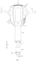
- Fig.1 shows a schematic view of an embodiment of a hand-held power tool 1.
- the hand-held power tool 1 is in particular a demolition hammer or chisel hammer.
- the hand-held power tool 1 comprises a machine body 2, on which in the orientation of the Fig.1
- a handle 3, 4 is provided on the left and right.
- the handles 3, 4 are mounted on the machine body 2 in a vibration-decoupled manner.
- the machine body 2 comprises several housings 5 to 7.
- a drive of the hand-held power tool 1 can be accommodated in a first housing 5.
- a Fig.1 The second housing 6 arranged on the underside of the first housing 5 can be suitable for accommodating an impact mechanism of the hand-held power tool 1.
- a third housing 7 is provided on the underside of the second housing 6.
- the third housing 7 can be screwed to the second housing 6, for example.
- a tool holder 8 can be mounted in or on the third housing 7 in a linearly movable manner.
- the tool holder 8 moves up and down in a vertical direction V.
- the vertical direction V can be in the orientation of the Fig.1 be oriented from top to bottom.
- the vertical direction V can coincide with a direction of gravity.
- a tool 9 is accommodated in the tool holder 8.
- the tool 9 can be a chisel, for example.
- the tool 9 can be hexagonal in cross section.
- the tool 9 comprises a locking collar 10 which runs around the tool 9 and whose function is explained below.
- the locking collar 10 can be hexagonal in cross section.
- the locking collar 10 can also be circular. In the Fig.8 and 9 the locking collar is provided with the reference number 10 in an operating point of the tool 9, and in an idle position of the tool 9 the locking collar is provided with the reference number 10'.
- the tool holder 8 comprises a receiving element 11 for receiving the tool 9.
- the receiving element 11 is designed to be rotationally symmetrical to a symmetry or central axis M11.
- the receiving element 11 comprises a cylindrical or cylinder-shaped outer geometry 12 that is designed to be rotationally symmetrical to the central axis M11.
- the outer geometry 12 can, for example, be a cylindrical outer surface of the receiving element 11.
- the receiving element 11 is mounted in the housing 7 so that it can move along the vertical direction V.
- the receiving element 11 comprises a receiving area for receiving the tool 9.
- the receiving area can, for example, be designed as a hexagon socket into which the tool 9 is inserted.
- the receiving element 11 is accommodated in an eccentric element 13.
- the eccentric element 13 is preferably connected to the receiving element 11 in a rotationally fixed manner. This means that the eccentric element 13 cannot rotate relative to the receiving element 11.
- the eccentric element 13 can be formed in one piece with the receiving element 11. This means that the receiving element 11 and the eccentric element 13 can form a common component, in particular one-piece component.
- the eccentric element 13 has a circular cylindrical shape with a cylindrical inner geometry 14 in which the receiving element 11 is received.
- the inner geometry 14 can be, for example, a cylindrical inner surface of the eccentric element 13.
- the inner geometry 14 is an opening that breaks through the eccentric element 13 along its entire length.
- the outer geometry 12 of the receiving element 11 rests against the inner geometry 14 of the eccentric element 13.
- the inner geometry 14 is designed to be rotationally symmetrical to the central axis M11.
- the eccentric element 13 also comprises a cylindrical outer geometry 15, which is constructed rotationally symmetrically to an eccentric axis E.
- the eccentric axis E is constructed eccentrically to the central axis M11.
- eccentric is to be understood to mean that the eccentric axis E is arranged parallel to and at a distance from the central axis M11.
- the eccentric element 13 also comprises two end faces 16 which are arranged parallel to and at a distance from one another and which are oriented perpendicularly to both the inner geometry 14 and the outer geometry 15.
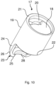
- the tool holder 8 also includes a Fig. 2 to 14 shown locking element 17.
- the locking element 17 is sleeve-shaped and can therefore also be referred to as a locking sleeve.
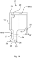
- the locking element 17 comprises a cylindrical inner geometry 18 in which the eccentric element 13 is accommodated.
- the inner geometry 18 is a cylindrical inner surface of the locking element 17.
- the inner geometry 18 of the locking element 17 can be rotatably mounted on the outer geometry 15 of the eccentric element 13.
- the inner geometry 18 is rotationally symmetrical to a symmetry or central axis M18 ( Fig. 11 to 14 ) of the locking element 17.
- the central axis M18 coincides with the eccentric axis E.
- the locking element 17 further comprises a cylindrical outer geometry 19 arranged eccentrically to the inner geometry 18.
- the outer geometry 19 is, for example, a cylindrical outer surface of the locking element 17.
- the outer geometry 19 is rotationally symmetrical to a symmetry or central axis M19 ( Fig. 11 to 14 ) of the locking element 17.
- the central axes M18, M19 are arranged eccentrically. This means that the central axis M19 is positioned parallel to the central axis M18 and at a distance from it. This means in particular that the central axis M19 does not coincide with the central axis M18.
- the locking element 17 does not have a constant, but a varying wall thickness W all around. In this way, a significant weight saving can be achieved compared to a constant wall thickness.
- the locking element 17 further comprises a fastening shoulder 20 extending radially onto the central axes M18, M19 and extending out of the inner geometry 18.
- the fastening shoulder 20 can, for example, engage in the eccentric element 13 in such a way that the locking element 17 is fixed to the eccentric element 13 in a captive and rotatable manner.
- the locking element 17 further comprises two end faces 21, 22 arranged parallel to one another and spaced apart from one another.
- the end faces 21, 22 are oriented perpendicular to the central axes M18, M19.
- a retaining collar 23 extends from the end face 22 and is designed to positively engage the locking collar 10 of the tool 9.
- a positive connection is created by the interlocking or engaging behind at least two connection partners, in this case the retaining collar 23 and the locking collar 10.
- the retaining collar 23 comprises a partially cylindrical base section 24 that extends out from the end face 22.
- “partially cylindrical” means that the base section 24 is formed using part of a cylinder, in particular part of a hollow cylinder.
- the base section 24 is not closed around the circumference, but rather open.
- the base section 24 is partially closed at the end or front by a retaining section 25.
- a spherical, in particular spherical cap-shaped, curved connecting section 26 can be provided between the base section 24 and the retaining section 25.
- An opening or window 27 is also provided in the base section 24.
- the retaining section 25 also comprises an arcuately curved recess 28 through which the tool 9 is guided.
- the recess 28 can be designed to be rotationally symmetrical to the central axis M18.
- the locking element 17 can be moved by a Fig. 2 to 5 shown unlocking state Z1, in which the tool 9 can be pulled out of the receiving element 11 in the vertical direction V and in which the retaining collar 23 does not engage around or behind the locking collar 10 in a form-fitting manner, into a Fig. 6 to 9 shown locking state Z2, in which the locking element 17 positively engages the tool 9 and in particular the locking collar 10, and vice versa.
- the locking element 17 is rotated around the receiving element 11 and in particular around the eccentric element 13, as shown in the Fig.6 indicated by a double arrow 29.
- the locking element 17 is rotated about the eccentric axis E.
- the retaining collar 23 pivots when the locking element 17 is moved from the unlocking state Z1 ( Fig.3 ) into the locking state Z2 ( Fig.7 ) over the locking collar 10 of the tool 9 in such a way that the tool 9 is positively locked in the receiving element 11.
- the retaining collar 23 thus engages around or behind the locking collar 10 in a positively locking manner. Pulling the tool 9 out of the tool holder 8 in the vertical direction V is therefore not possible in the locking state Z2.
Landscapes
- Engineering & Computer Science (AREA)
- Mechanical Engineering (AREA)
- Percussive Tools And Related Accessories (AREA)
Description
- Die vorliegende Erfindung betrifft eine Werkzeugaufnahme für eine Handwerkzeugmaschine und eine Handwerkzeugmaschine mit einer derartigen Werkzeugaufnahme.
- Ein Abbruchhammer oder Meißelhammer umfasst eine Werkzeugaufnahme, in der ein Werkzeug, wie beispielsweise ein Meißel, aufgenommen werden kann. Eine derartige Werkzeugaufnahme kann eine Verriegelungseinrichtung zum Verriegeln des Werkzeugs in der Werkzeugaufnahme in Form eines Klappmechanismus aufweisen. Ein derartiger Klappmechanismus umfasst ein Verriegelungselement, das senkrecht zu einer Mittelachse des Werkzeugs klappbar ist, um das Werkzeug in der Werkzeugaufnahme zu arretieren und wieder freizugeben. Ein derartiger Klappmechanismus ist im Neuzustand zumeist schwergängig und nach einiger Betriebszeit der Handwerkzeugmaschine oftmals so verschlissen, dass dieser sich von selbst öffnet und das Werkzeug aus der Werkzeugaufnahme herausfallen kann.
-
DE838734C offenbart einen Abbauhammer, insbesondere für unterirdische Grubenbetriebe, mit einer Sicherungsvorrichtung zum Verhindern des ungewollten Herausrutschens des Meißels aus seiner Führung. - Eine Aufgabe der vorliegenden Erfindung ist es, eine verbesserte Werkzeugaufnahme für eine Handwerkzeugmaschine bereitzustellen.
- Erfindungsgemäß wird eine Werkzeugaufnahme für eine Handwerkzeugmaschine, insbesondere für einen Abbruchhammer oder Meißelhammer, nach Anspruch 1 vorgeschlagen. Die Werkzeugaufnahme umfasst ein Aufnahmeelement zum Aufnehmen eines Werkzeugs, und ein exzentrisch und drehbar an dem Aufnahmeelement gelagertes Verriegelungselement zum Verriegeln des Werkzeugs in der Werkzeugaufnahme, wobei das Verriegelungselement mit Hilfe eines Verdrehens desselben um das Aufnahmeelement von einem Entriegelungszustand, in dem das Werkzeug aus dem Aufnahmeelement entnehmbar ist, in einen Verriegelungszustand, in dem das Verriegelungselement das Werkzeug formschlüssig umgreift, und umgekehrt verbringbar ist.
- Durch das exzentrische Verschwenken des Verriegelungselements um das Aufnahmeelement kann auf einen wie zuvor erwähnten verschleißbehafteten Klappmechanismus verzichtet werden. Dies erhöht die Betriebszuverlässigkeit der Werkzeugaufnahme.
- Das Aufnahmeelement umfasst einen Aufnahmeabschnitt zum Aufnehmen des Werkzeugs. Der Aufnahmeabschnitt kann beispielsweise eine sechseckige Innengeometrie aufweisen, wobei das Werkzeug dementsprechend eine sechseckige Außengeometrie aufweist. Die Werkzeugaufnahme ist vorzugsweise derart an der Handwerkzeugmaschine gelagert, dass die Werkzeugaufnahme eine lineare Bewegung vollführen kann. Die Handwerkzeugmaschine kann zum linearen Bewegen der Werkzeugaufnahme ein Schlagwerk umfassen. Das Schlagwerk kann beispielsweise mit Hilfe eines Elektromotors angetrieben werden. Das Werkzeug kann einen, insbesondere umlaufenden, Verriegelungsbund umfassen, den das Verriegelungselement in dem Verriegelungszustand formschlüssig umgreift oder hintergreift. Der Entriegelungszustand kann auch als Entriegelungsposition, und der Verriegelungszustand kann auch als Verriegelungsposition bezeichnet werden.
- Darunter, dass das Verriegelungselement "exzentrisch" an dem Aufnahmeelement gelagert ist, ist zu verstehen, dass eine Mittelachse des Aufnahmeelements und eine Drehachse oder Exzenterachse des Verriegelungselements nicht übereinstimmen. Das heißt, das Verriegelungselement ist bevorzugt außermittig um das oder an dem Aufnahmeelement gelagert. Unter einer formschlüssigen Verbindung ist vorliegend eine Verbindung zu verstehen, bei der zwei Verbindungspartner, vorliegend das Verriegelungselement und das Werkzeug, ineinandergreifen oder sich hintergreifen. In dem Entriegelungszustand ist diese formschlüssige Verbindung aufgehoben, so dass das Werkzeug aus dem Aufnahmeelement herausgezogen werden kann. In dem Verriegelungszustand ist ein Entnehmen des Werkzeugs aus dem Aufnahmeelement nicht möglich, da das Verriegelungselement das Werkzeug formschlüssig umgreift oder hintergreift. Das Verriegelungselement kann auch als Verriegelungshülse bezeichnet werden oder ist eine Verriegelungshülse.
- Gemäß einer bevorzugten Ausführungsform rastet das Verriegelungselement sowohl in den Entriegelungszustand als auch in den Verriegelungszustand ein.
- Hierzu kann eine Rasteinrichtung vorgesehen sein. Die Rasteinrichtung kann beispielsweise eine federvorgespannte Kugel oder einen federvorgespannten Bolzen umfassen.
- Beispielsweise kann das Verriegelungselement sowohl in Richtung des Entriegelungszustands als auch in Richtung des Verriegelungszustands federvorgespannt sein, so dass zwischen dem Entriegelungszustand und dem Verriegelungszustand keine Zwischenposition des Verriegelungselements möglich ist. Dies vereinfacht die Handhabung der Werkzeugaufnahme.
- Gemäß der Erfindung umfasst die Werkzeugaufnahme eine dem Aufnahmeelement zugeordnete Mittelachse und eine dem Verriegelungselement zugeordnete Exzenterachse, um die das Verriegelungselement drehbar gelagert ist, wobei die Exzenterachse parallel zu und beabstandet von der Mittelachse angeordnet ist.
- Vorzugsweise ist das Aufnahmeelement rotationssymmetrisch zu der Mittelachse aufgebaut. Die Exzenterachse ist exzentrisch zu der Mittelachse angeordnet. Unter "exzentrisch" in Bezug auf die Achsen ist vorliegend zu verstehen, dass die Exzenterachse parallel zu und beabstandet von der Mittelachse angeordnet ist. Das heißt, die Exzenterachse stimmt nicht mit der Mittelachse überein.
- Gemäß einer weiteren bevorzugten Ausführungsform ist das Verriegelungselement mit Hilfe eines Verdrehens desselben um die Exzenterachse von dem Entriegelungszustand in den Verriegelungszustand und umgekehrt verbringbar.
- Das heißt, das Verriegelungselement ist bezüglich der Mittelachse des Aufnahmeelements außermittig um das Aufnahmeelement gelagert. Das Verriegelungselement kann direkt an dem Aufnahmeelement drehbar gelagert sein. Somit kann das Verriegelungselement unmittelbar an dem Aufnahmeelement drehbar gelagert sein. Alternativ kann das Verriegelungselement mittelbar an dem Aufnahmeelement drehbar gelagert sein. In diesem Fall kann zwischen dem Aufnahmeelement und dem Verriegelungselement ein weiteres Element oder Bauteil vorgesehen sein, an dem das Verriegelungselement drehbar gelagert ist.
- Gemäß der Erfindung umfasst die Werkzeugaufnahme ein Exzenterelement, das zwischen dem Aufnahmeelement und dem Verriegelungselement angeordnet ist.
- Das Exzenterelement und das Aufnahmeelement können zwei voneinander getrennte Bauteile sein. Alternativ kann das Exzenterelement auch einteilig mit dem Aufnahmeelement ausgebildet sein. Beispielsweise ist das Verriegelungselement drehbar an dem Exzenterelement gelagert. Hierzu kann eine Gleitlagerung oder eine Wälzlagerung vorgesehen sein.
- Gemäß einer weiteren bevorzugten Ausführungsform weist das Exzenterelement eine zylindrische Innengeometrie, in der das Aufnahmeelement aufgenommen ist und die rotationssymmetrisch zu der Mittelachse aufgebaut ist, und eine exzentrisch zu der Innengeometrie angeordnete zylindrische Außengeometrie auf, die in dem Verriegelungselement aufgenommen ist und die rotationssymmetrisch zu der Exzenterachse aufgebaut ist.
- Die zuvor erwähnte Mittelachse ist die Mittelachse des Aufnahmeelements. Die zuvor erwähnte Exzenterachse ist die Exzenterachse des Verriegelungselements. Die Exzenterachse kann auch dem Exzenterelement zugeordnet sein. Die zylindrische Innengeometrie des Exzenterelements kann eine zylindrische Innenfläche einer das Exzenterelement durchbrechenden Ausnehmung oder Bohrung sein. Das Exzenterelement ist vorzugsweise zylinderförmig und umfasst zwei beabstandet voneinander und parallel zueinander angeordnete Stirnflächen. Die zylindrische Außengeometrie des Exzenterelements kann eine zylindrische Außenfläche desselben sein. An der zylindrischen Außengeometrie des Exzenterelements kann das Verriegelungselement drehbar gelagert sein. Darunter, dass die Innengeometrie und die Außengeometrie des Exzenterelements exzentrisch zueinander angeordnet sind, ist zu verstehen, dass diese keine gemeinsame Mittelachse aufweisen. Die Außengeometrie kann auch an dem Aufnahmeelement vorgesehen sein. In diesem Fall ist das Exzenterelement optional.
- Gemäß einer weiteren bevorzugten Ausführungsform weist das Aufnahmeelement eine zylindrische Außengeometrie auf, die in der Innengeometrie des Exzenterelements aufgenommen ist und die rotationssymmetrisch zu der Mittelachse aufgebaut ist.
- Die zylindrische Außengeometrie des Aufnahmeelements kann eine zylindrische Außenfläche desselben sein. Die Außengeometrie des Aufnahmeelements liegt bevorzugt an der Innengeometrie des Exzenterelements an.
- Gemäß einer weiteren bevorzugten Ausführungsform ist das Exzenterelement gegenüber dem Aufnahmeelement drehfest, wobei das Verriegelungselement gegenüber dem Exzenterelement drehbar ist.
- Beispielsweise ist das Exzenterelement mit dem Aufnahmeelement fest verbunden, insbesondere verschraubt. Das Verriegelungselement kann drehbar an dem Exzenterelement gelagert sein. Hierzu kann eine Lagereinrichtung, wie beispielsweise eine Gleitlagerung oder eine Wälzlagerung, vorgesehen sein.
- Gemäß der Erfindung weist das Verriegelungselement eine zylindrische Innengeometrie, in der das Exzenterelement aufgenommen ist, und eine zylindrische Außengeometrie auf, die exzentrisch zu der Innengeometrie angeordnet ist.
- Vorzugsweise ist die zylindrische Innengeometrie eine zylindrische Innenfläche des Verriegelungselements. Die Innengeometrie des Verriegelungselements kann an der Außengeometrie des Exzenterelements anliegen. Die zylindrische Außengeometrie des Verriegelungselements kann eine zylindrische Außenfläche desselben sein. Die Innengeometrie des Verriegelungselements ist rotationssymmetrisch zu einer ersten Mittelachse des Verriegelungselements aufgebaut, und die Außengeometrie des Verriegelungselements ist rotationssymmetrisch zu einer zweiten Mittelachse des Verriegelungselements ausgebildet. Die beiden Mittelachsen sind parallel zueinander und beabstandet voneinander angeordnet. Das heißt, die Mittelachse der Innengeometrie und die Mittelachse der Außengeometrie sind exzentrisch zueinander positioniert.
- Gemäß einer weiteren bervorzugten Ausführungsform weist das Verriegelungselement einen Haltekragen auf, der das Werkzeug in dem Verriegelungszustand formschlüssig umgreift.
- Vorzugsweise umfasst das Werkzeug, wie zuvor erwähnt, einen umlaufenden Verriegelungsbund. Der Haltekragen ist dazu eingerichtet, den Verriegelungsbund so zu hintergreifen oder zu umgreifen, dass das Werkzeug in dem Verriegelungszustand nicht aus dem Aufnahmeelement herausgezogen werden kann.
- Gemäß einer weiteren bevorzugten Ausführungsform erstreckt sich der Haltekragen aus einer Stirnfläche des Verriegelungselements heraus.
- Vorzugsweise umfasst das Verriegelungselement zwei parallel zueinander und beabstandet voneinander angeordnete Stirnflächen. Aus einer der beiden Stirnflächen erstreckt sich der Haltekragen heraus.
- Gemäß einer weiteren bevorzugten Ausführungsform weist der Haltekragen einen parallel zu der Stirnfläche angeordneten Halteabschnitt mit einer Ausnehmung auf, wobei der Halteabschnitt in dem Verriegelungszustand das Werkzeug formschlüssig umgreift und wobei das Werkzeug in dem Verriegelungszustand durch die Ausnehmung hindurchgeführt ist.
- Vorzugsweise umfasst der Haltekragen einen sich aus der Stirnfläche heraus erstreckenden teilzylinderförmigen Basisabschnitt, der mit Hilfe eines insbesondere kugelkalottenförmig gekrümmten Verbindungsabschnitts mit dem Halteabschnitt einteilig verbunden ist. Der Halteabschnitt schließt das Verriegelungselement vorderseitig oder stirnseitig zumindest teilweise ab. Die Ausnehmung ist vorzugsweise bogenförmig, insbesondere kreisbogenförmig, gekrümmt.
- Gemäß einer weiteren bevorzugten Ausführungsform weist das Verriegelungselement eine rohrförmige Geometrie mit einer variablen Wandstärke auf.
- Vorzugsweise ist die Wandstärke im Bereich des Haltekragens größer als in einem Bereich, in dem der Haltekragen nicht vorgesehen ist. Hierdurch kann in Bereichen des Verriegelungselements, die mechanisch nicht stark beansprucht sind, eine geringere Wandstärke vorgesehen werden. Dadurch kann im Vergleich zu einer konstanten Wandstärke eine signifikante Gewichtsersparnis erreicht werden.
- Ferner wird eine Handwerkzeugmaschine mit einer derartigen Werkzeugaufnahme vorgeschlagen.
- Die Handwerkzeugmaschine ist vorzugsweise ein Abbruchhammer oder Meißelhammer. Vorzugsweise umfasst die Handwerkzeugmaschine einen Antrieb, insbesondere einen Elektromotor, der dazu eingerichtet ist, die Werkzeugaufnahme linear hin- und herzubewegen, um das Werkzeug zu betätigen. Das Werkzeug kann beispielsweise ein Meißel sein.
- Gemäß einer bevorzugten Ausführungsform umfasst die Handwerkzeugmaschine ein in dem Aufnahmeelement aufgenommenes Werkzeug, das einen Verriegelungsbund aufweist, den das Verriegelungselement in dem Verriegelungszustand formschlüssig umgreift, um das Werkzeug in der Werkzeugaufnahme zu verriegeln.
- Vorzugsweise läuft der Verriegelungsbund vollständig um das Werkzeug um. Alternativ kann der Verriegelungsbund auch nur teilweise um das Werkzeug umlaufen. Im Bereich des Verriegelungsbundes weist das Werkzeug einen vergrößerten Durchmesser auf. Der Verriegelungsbund kann ringförmig sein. Der Verriegelungsbund kann auch vieleckig, insbesondere sechseckig, sein.
- Die nachfolgende Beschreibung erläutert die Erfindung anhand von exemplarischen Ausführungsformen und Figuren. In den Figuren zeigt:
- Fig. 1
- eine schematische Ansicht einer Ausführungsform einer Handwerkzeugmaschine;
- Fig. 2
- eine schematische perspektivische Ansicht einer Ausführungsform einer Werkzeugaufnahme für die Handwerkzeugmaschine gemäß
Fig. 1 ; - Fig. 3
- eine schematische Aufsicht der Werkzeugaufnahme gemäß
Fig. 2 ; - Fig. 4
- eine schematische Seitenansicht der Werkzeugaufnahme gemäß
Fig. 2 ; - Fig. 5
- eine weitere schematische Seitenansicht der Werkzeugaufnahme gemäß
Fig. 2 ; - Fig. 6
- eine weitere schematische perspektivische Ansicht der Werkzeugaufnahme gemäß
Fig. 2 ; - Fig. 7
- eine weitere schematische Aufsicht der Werkzeugaufnahme gemäß
Fig. 2 ; - Fig. 8
- eine weitere schematische Seitenansicht der Werkzeugaufnahme gemäß
Fig. 2 ; - Fig. 9
- eine weitere schematische Seitenansicht der Werkzeugaufnahme gemäß
Fig. 2 ; - Fig. 10
- eine schematische perspektivische Ansicht einer Ausführungsform eines Verriegelungselements für die Werkzeugaufnahme gemäß
Fig. 2 ; - Fig. 11
- eine schematische Aufsicht des Verriegelungselements gemäß
Fig. 10 ; - Fig. 12
- eine schematische Seitenansicht des Verriegelungselements gemäß
Fig. 10 ; - Fig. 13
- eine schematische Schnittansicht des Verriegelungselements gemäß der Schnittlinie XIII-XIII der
Fig. 12 ; und - Fig. 14
- eine weitere schematische Schnittansicht des Verriegelungselements gemäß der Schnittlinie XIV-XIV der
Fig. 12 . - Gleiche oder funktionsgleiche Elemente werden durch gleiche Bezugszeichen in den Figuren indiziert, soweit nichts anderes angegeben ist.
-
Fig. 1 zeigt eine schematische Ansicht einer Ausführungsform einer Handwerkzeugmaschine 1. Die Handwerkzeugmaschine 1 ist insbesondere ein Abbruchhammer oder Meißelhammer. Die Handwerkzeugmaschine 1 umfasst einen Maschinenkörper 2, an dem in der Orientierung derFig. 1 links und rechts jeweils ein Handgriff 3, 4 vorgesehen ist. Die Handgriffe 3, 4 sind schwingungsentkoppelt an dem Maschinenkörper 2 gelagert. Der Maschinenkörper 2 umfasst mehrere Gehäuse 5 bis 7. In einem ersten Gehäuse 5 kann ein Antrieb der Handwerkzeugmaschine 1 aufgenommen sein. Ein in der Orientierung derFig. 1 unterseitig an dem ersten Gehäuse 5 angeordnetes zweites Gehäuse 6 kann zur Aufnahme eines Schlagwerks der Handwerkzeugmaschine 1 geeignet sein. Unterseitig an dem zweiten Gehäuse 6 ist ein drittes Gehäuse 7 vorgesehen. - Das dritte Gehäuse 7 kann beispielsweise mit dem zweiten Gehäuse 6 verschraubt sein. In oder an dem dritten Gehäuse 7 kann eine Werkzeugaufnahme 8 linear beweglich gelagert sein. Im Betrieb der Handwerkzeugmaschine 1 bewegt sich die Werkzeugaufnahme 8 in einer Vertikalrichtung V auf und ab. Die Vertikalrichtung V kann dabei in der Orientierung der
Fig. 1 von oben nach unten orientiert sein. Die Vertikalrichtung V kann mit einer Schwerkraftrichtung übereinstimmen. - In der Werkzeugaufnahme 8 ist ein Werkzeug 9 aufgenommen. Das Werkzeug 9 kann beispielsweise ein Meißel sein. Das Werkzeug 9 kann im Querschnitt sechseckig sein. Das Werkzeug 9 umfasst einen um dasselbe umlaufenden Verriegelungsbund 10, dessen Funktion nachfolgend noch erläutert wird. Der Verriegelungsbund 10 kann im Querschnitt sechseckig sein. Der Verriegelungsbund 10 kann jedoch auch kreisrund sein. In den
Fig. 8 und9 ist der Verriegelungsbund in einem Arbeitspunkt des Werkzeugs 9 mit dem Bezugszeichen 10 versehen, und in einer Leerschlagposition des Werkzeugs 9 ist der Verriegelungsbund mit dem Bezugszeichen 10' versehen. - Wie in den
Fig. 3 und7 gezeigt, umfasst die Werkzeugaufnahme 8 ein Aufnahmeelement 11 zum Aufnehmen des Werkzeugs 9. Das Aufnahmeelement 11 ist rotationssymmetrisch zu einer Symmetrie- oder Mittelachse M11 ausgebildet. Das Aufnahmeelement 11 umfasst eine rotationssymmetrisch zu der Mittelachse M11 aufgebaute zylindrische oder zylinderförmige Außengeometrie 12. Die Außengeometrie 12 kann beispielsweise eine zylinderförmige Außenfläche des Aufnahmeelements 11 sein. Das Aufnahmeelement 11 ist in dem Gehäuse 7 entlang der Vertikalrichtung V verschieblich gelagert. Das Aufnahmeelement 11 umfasst einen Aufnahmebereich zum Aufnehmen des Werkzeugs 9. Der Aufnahmebereich kann beispielsweise als Innensechskant ausgebildet sein, in den das Werkzeug 9 eingesteckt wird. - Das Aufnahmeelement 11 ist in einem Exzenterelement 13 aufgenommen. Das Exzenterelement 13 ist vorzugsweise drehfest mit dem Aufnahmeelement 11 verbunden. Das heißt, das Exzenterelement 13 kann sich gegenüber dem Aufnahmeelement 11 nicht verdrehen. Das Exzenterelement 13 kann einteilig mit dem Aufnahmeelement 11 ausgebildet sein. Das heißt, das Aufnahmeelement 11 und das Exzenterelement 13 können ein gemeinsames, insbesondere materialeinstückiges, Bauteil bilden.
- Das Exzenterelement 13 weist eine kreiszylinderförmige Form mit einer zylindrischen Innengeometrie 14, in der das Aufnahmeelement 11 aufgenommen ist, auf. Die Innengeometrie 14 kann beispielsweise eine zylinderförmige Innenfläche des Exzenterelements 13 sein. Beispielsweise ist die Innengeometrie 14 ein das Exzenterelement 13 auf seiner gesamten Länge durchbrechender Durchbruch. Die Außengeometrie 12 des Aufnahmeelements 11 liegt an der Innengeometrie 14 des Exzenterelements 13 an. Die Innengeometrie 14 ist dabei rotationssymmetrisch zu der Mittelachse M11 aufgebaut.
- Weiterhin umfasst das Exzenterelement 13 eine zylindrische Außengeometrie 15, die rotationssymmetrisch zu einer Exzenterachse E aufgebaut ist. Die Exzenterachse E ist exzentrisch zu der Mittelachse M11 aufgebaut. Unter "exzentrisch" ist vorliegend zu verstehen, dass die Exzenterachse E parallel zu und beabstandet von der Mittelachse M11 angeordnet ist. Das Exzenterelement 13 umfasst weiterhin zwei parallel zueinander und beabstandet voneinander angeordnete Stirnflächen 16, die sowohl senkrecht zu der Innengeometrie 14 als auch zu der Außengeometrie 15 orientiert sind.
- Die Werkzeugaufnahme 8 umfasst weiterhin ein in den
Fig. 2 bis 14 gezeigtes Verriegelungselement 17. Das Verriegelungselement 17 ist hülsenförmig und kann daher auch als Verriegelungshülse bezeichnet werden. Das Verriegelungselement 17 umfasst eine zylindrische Innengeometrie 18, in der das Exzenterelement 13 aufgenommen ist. Beispielsweise ist die Innengeometrie 18 eine zylindrische Innenfläche des Verriegelungselements 17. Beispielsweise kann die Innengeometrie 18 des Verriegelungselements 17 drehbar an der Außengeometrie 15 des Exzenterelements 13 gelagert sein. Die Innengeometrie 18 ist rotationssymmetrisch zu einer Symmetrie- oder Mittelachse M18 (Fig. 11 bis 14 ) des Verriegelungselements 17 ausgebildet. Die Mittelachse M18 stimmt mit der Exzenterachse E überein. - Das Verriegelungselement 17 umfasst weiterhin eine exzentrisch zu der Innengeometrie 18 angeordnete zylindrische Außengeometrie 19. Die Außengeometrie 19 ist beispielsweise eine zylindrische Außenfläche des Verriegelungselements 17. Die Außengeometrie 19 ist rotationssymmetrisch zu einer Symmetrie- oder Mittelachse M19 (
Fig. 11 bis 14 ) des Verriegelungselements 17 ausgebildet. Die Mittelachsen M18, M19 sind exzentrisch angeordnet. Das heißt, die Mittelachse M19 ist parallel zu der Mittelachse M18 und beabstandet zu dieser positioniert. Das heißt insbesondere, dass die Mittelachse M19 nicht mit der Mittelachse M18 übereinstimmt. - Dadurch, dass die Innengeometrie 18 und die Außengeometrie 19 exzentrisch zueinander positioniert sind, kann, wie in den
Fig. 13 und14 gezeigt, erreicht werden, dass das Verriegelungselement 17 umlaufend keine konstante, sondern eine variierende Wandstärke W aufweist. Hierdurch kann im Vergleich zu einer konstanten Wandstärke eine signifikante Gewichtsersparnis erzielt werden. - Das Verriegelungselement 17 umfasst weiterhin einen sich radial auf die Mittelachsen M18, M19 zu erstreckenden und aus der Innengeometrie 18 heraus erstreckenden Befestigungsabsatz 20. Der Befestigungsabsatz 20 kann beispielsweise in das Exzenterelement 13 derart eingreifen, dass das Verriegelungselement 17 verlierfest und drehbar an dem Exzenterelement 13 befestigt ist.
- Das Verriegelungselement 17 umfasst weiterhin zwei parallel zueinander und beabstandet voneinander angeordnete Stirnflächen 21, 22. Die Stirnflächen 21, 22 sind senkrecht zu den Mittelachsen M18, M19 orientiert. Aus der Stirnfläche 22 heraus erstreckt sich ein Haltekragen 23, der dazu eingerichtet ist, den Verriegelungsbund 10 des Werkzeugs 9 formschlüssig zu umgreifen. Eine formschlüssige Verbindung entsteht durch das Ineinander- oder Hintergreifen von mindestens zwei Verbindungspartnern, vorliegend dem Haltekragen 23 und dem Verriegelungsbund 10.
- Der Haltekragen 23 umfasst einen teilzylinderförmigen Basisabschnitt 24, der sich aus der Stirnfläche 22 heraus erstreckt. Unter "teilzylinderförmig" ist vorliegend zu verstehen, dass der Basisabschnitt 24 mit Hilfe eines Teils eines Zylinders, insbesondere eines Teils eines Hohlzylinders, geformt wird. Insbesondere ist der Basisabschnitt 24 umfänglich nicht geschlossen, sondern offen. Der Basisabschnitt 24 ist stirnseitig oder vorderseitig durch einen Halteabschnitt 25 teilweise verschlossen. Zwischen dem Basisabschnitt 24 und dem Halteabschnitt 25 kann ein kugelförmig, insbesondere kugelkalottenförmig, gekrümmter Verbindungsabschnitt 26 vorgesehen sein. In dem Basisabschnitt 24 ist ferner ein Durchbruch oder Fenster 27 vorgesehen. Der Halteabschnitt 25 umfasst weiterhin eine bogenförmig gekrümmte Ausnehmung 28, durch die das Werkzeug 9 hindurchgeführt ist. Die Ausnehmung 28 kann rotationssymmetrisch zu der Mittelachse M18 aufgebaut sein.
- Die Funktionalität der Werkzeugaufnahme 8 wird nachfolgend anhand der
Fig. 2 bis 9 erläutert. Das Verriegelungselement 17 kann von einem in denFig. 2 bis 5 gezeigten Entriegelungszustand Z1, in dem das Werkzeug 9 in der Vertikalrichtung V aus dem Aufnahmeelement 11 herausziehbar ist und in dem der Haltekragen 23 den Verriegelungsbund 10 nicht formschlüssig umgreift oder hintergreift, in einen in denFig. 6 bis 9 gezeigten Verriegelungszustand Z2, in dem das Verriegelungselement 17 das Werkzeug 9 und insbesondere den Verriegelungsbund 10 formschlüssig umgreift, und umgekehrt verbracht werden. Hierzu wird das Verriegelungselement 17 um das Aufnahmeelement 11 und insbesondere um das Exzenterelement 13 verdreht, wie in derFig. 6 mit Hilfe eines Doppelpfeils 29 angedeutet. Das Verriegelungselement 17 wird um die Exzenterachse E verdreht. - Aufgrund der exzentrischen Lagerung des Verriegelungselements 17 verschwenkt der Haltekragen 23 bei dem Verbringen des Verriegelungselements 17 von dem Entriegelungszustand Z1 (
Fig. 3 ) in den Verriegelungszustand Z2 (Fig. 7 ) derart über den Verriegelungsbund 10 des Werkzeugs 9, dass das Werkzeug 9 formschlüssig in dem Aufnahmeelement 11 verriegelt ist. In dem Verriegelungszustand Z2 umgreift oder hintergreift der Haltekragen 23 den Verriegelungsbund 10 somit formschlüssig. Ein Herausziehen des Werkzeugs 9 aus der Werkzeugaufnahme 8 in der Vertikalrichtung V ist somit in dem Verriegelungszustand Z2 nicht möglich. - Umgekehrt verschwenkt der Haltekragen 23 bei dem Verbringen des Verriegelungselements 17 von dem Verriegelungszustand Z2 in den Entriegelungszustand Z1 so von dem Werkzeug 9 weg, dass dieses in der Vertikalrichtung V aus dem Aufnahmeelement 11 herausgezogen werden kann, ohne dass der Haltekragen 23 in Kontakt mit dem Verriegelungsbund 10 gerät. Wie die
Fig. 3 zeigt, ist es aufgrund der exzentrischen Lagerung des Verriegelungselements 17 möglich, dass der Haltekragen 23 in dem Entriegelungszustand Z1 so angeordnet ist, dass der Verriegelungsbund 10 durch die Ausnehmung 28 des Haltekragens 23 herausführbar ist. Mit Hilfe der Werkzeugaufnahme 8 ist somit eine einfache und schnelle Verriegelung und Entriegelung des Werkzeugs 9 in der Werkzeugaufnahme 8 möglich. -
- 1
- Handwerkzeugmaschine
- 2
- Maschinenkörper
- 3
- Handgriff
- 4
- Handgriff
- 5
- Gehäuse
- 6
- Gehäuse
- 7
- Gehäuse
- 8
- Werkzeugaufnahme
- 9
- Werkzeug
- 10
- Verriegelungsbund
- 10'
- Verriegelungsbund
- 11
- Aufnahmeelement
- 12
- Außengeometrie
- 13
- Exzenterelement
- 14
- Innengeometrie
- 15
- Außengeometrie
- 16
- Stirnfläche
- 17
- Verriegelungselement
- 18
- Innengeometrie
- 19
- Außengeometrie
- 20
- Befestigungsabsatz
- 21
- Stirnfläche
- 22
- Stirnfläche
- 23
- Haltekragen
- 24
- Basisabschnitt
- 25
- Halteabschnitt
- 26
- Verbindungsabschnitt
- 27
- Fenster
- 28
- Ausnehmung
- 29
- Doppelpfeil
- E
- Exzenterachse
- M11
- Mittelachse
- M18
- Mittelachse
- M19
- Mittelachse
- V
- Vertikalrichtung
- W
- Wandstärke
- Z1
- Entriegelungszustand
- Z2
- Verriegelungszustand
Claims (12)
- Werkzeugaufnahme (8) für eine Handwerkzeugmaschine (1), insbesondere für einen Abbruchhammer oder Meißelhammer, mit einem Aufnahmeelement (11) zum Aufnehmen eines Werkzeugs (9), und einem exzentrisch und drehbar um das Aufnahmeelement (11) gelagerten Verriegelungselement (17) zum Verriegeln des Werkzeugs (9) in der Werkzeugaufnahme (8), wobei das Verriegelungselement (17) mit Hilfe eines Verdrehens desselben um das Aufnahmeelement (11) von einem Entriegelungszustand (Z1), in dem das Werkzeug (9) aus dem Aufnahmeelement (11) entnehmbar ist, in einen Verriegelungszustand (Z2), in dem das Verriegelungselement (17) das Werkzeug (9) formschlüssig umgreift, und umgekehrt verbringbar ist, mit einer dem Aufnahmeelement (11) zugeordneten Mittelachse (M11) und einer dem Verriegelungselement (17) zugeordneten Exzenterachse (E), um die das Verriegelungselement (17) drehbar gelagert ist, wobei die Exzenterachse (E) parallel zu und beabstandet von der Mittelachse (M11) angeordnet ist, und mit einem Exzenterelement (13), das zwischen dem Aufnahmeelement (11) und dem Verriegelungselement (17) angeordnet ist, dadurch gekennzeichnet, dass das Verriegelungselement (17) eine zylindrische Innengeometrie (18), in der das Exzenterelement (13) aufgenommen ist, und eine zylindrische Außengeometrie (19) aufweist, die exzentrisch zu der Innengeometrie (18) angeordnet ist.
- Werkzeugaufnahme nach Anspruch 1, dadurch gekennzeichnet, dass das Verriegelungselement (17) sowohl in den Entriegelungszustand (Z1) als auch in den Verriegelungszustand (Z2) einrastet.
- Werkzeugaufnahme nach Anspruch 1, dadurch gekennzeichnet, dass das Verriegelungselement (17) mit Hilfe eines Verdrehens desselben um die Exzenterachse (E) von dem Entriegelungszustand (Z1) in den Verriegelungszustand (Z2) und umgekehrt verbringbar ist.
- Werkzeugaufnahme nach Anspruch 1, dadurch gekennzeichnet, dass das Exzenterelement (13) eine zylindrische Innengeometrie (14), in der das Aufnahmeelement (11) aufgenommen ist und die rotationssymmetrisch zu der Mittelachse (M11) aufgebaut ist, und eine exzentrisch zu der Innengeometrie (14) angeordnete zylindrische Außengeometrie (15) aufweist, die in dem Verriegelungselement (17) aufgenommen ist und die rotationssymmetrisch zu der Exzenterachse (E) aufgebaut ist.
- Werkzeugaufnahme nach Anspruch 4, dadurch gekennzeichnet, dass das Aufnahmeelement (11) eine zylindrische Außengeometrie (12) aufweist, die in der Innengeometrie (14) des Exzenterelements (13) aufgenommen ist und die rotationssymmetrisch zu der Mittelachse (M11) aufgebaut ist.
- Werkzeugaufnahme nach einem der Ansprüche 1 - 5, dadurch gekennzeichnet, dass das Exzenterelement (13) gegenüber dem Aufnahmeelement (11) drehfest ist, wobei das Verriegelungselement (17) gegenüber dem Exzenterelement (13) drehbar ist.
- Werkzeugaufnahme nach einem der Ansprüche 1 - 6, dadurch gekennzeichnet, dass das Verriegelungselement (17) einen Haltekragen (23) aufweist, der das Werkzeug (9) in dem Verriegelungszustand (Z2) formschlüssig umgreift.
- Werkzeugaufnahme nach Anspruch 7, dadurch gekennzeichnet, dass sich der Haltekragen (23) aus einer Stirnfläche (22) des Verriegelungselements (17) herauserstreckt.
- Werkzeugaufnahme nach Anspruch 8, dadurch gekennzeichnet, dass der Haltekragen (23) einen parallel zu der Stirnfläche (22) angeordneten Halteabschnitt (25) mit einer Ausnehmung (28) aufweist, wobei der Halteabschnitt (25) in dem Verriegelungszustand (Z2) das Werkzeug (9) formschlüssig umgreift, und wobei das Werkzeug (9) in dem Verriegelungszustand (Z2) durch die Ausnehmung (28) hindurchgeführt ist.
- Werkzeugaufnahme nach einem der Ansprüche 1 - 9, dadurch gekennzeichnet, dass das Verriegelungselement (17) eine rohrförmige Geometrie mit einer variablen Wandstärke (W) aufweist.
- Handwerkzeugmaschine (1) mit einer Werkzeugaufnahme (8) nach einem der Ansprüche 1 - 10.
- Handwerkzeugmaschine nach Anspruch 11, gekennzeichnet durch ein in dem Aufnahmeelement (11) aufgenommenes Werkzeug (9), das einen Verriegelungsbund (10, 10') aufweist, den das Verriegelungselement (17) in dem Verriegelungszustand (Z2) formschlüssig umgreift, um das Werkzeug (9) in der Werkzeugaufnahme (8) zu verriegeln.
Applications Claiming Priority (2)
| Application Number | Priority Date | Filing Date | Title |
|---|---|---|---|
| EP18184891.2A EP3599058A1 (de) | 2018-07-23 | 2018-07-23 | Werkzeugaufnahme und handwerkzeugmaschine |
| PCT/EP2019/068824 WO2020020667A1 (de) | 2018-07-23 | 2019-07-12 | Werkzeugaufnahme und handwerkzeugmaschine |
Publications (2)
| Publication Number | Publication Date |
|---|---|
| EP3826811A1 EP3826811A1 (de) | 2021-06-02 |
| EP3826811B1 true EP3826811B1 (de) | 2024-09-18 |
Family
ID=63035885
Family Applications (2)
| Application Number | Title | Priority Date | Filing Date |
|---|---|---|---|
| EP18184891.2A Withdrawn EP3599058A1 (de) | 2018-07-23 | 2018-07-23 | Werkzeugaufnahme und handwerkzeugmaschine |
| EP19737547.0A Active EP3826811B1 (de) | 2018-07-23 | 2019-07-12 | Werkzeugaufnahme und handwerkzeugmaschine |
Family Applications Before (1)
| Application Number | Title | Priority Date | Filing Date |
|---|---|---|---|
| EP18184891.2A Withdrawn EP3599058A1 (de) | 2018-07-23 | 2018-07-23 | Werkzeugaufnahme und handwerkzeugmaschine |
Country Status (4)
| Country | Link |
|---|---|
| US (1) | US12083662B2 (de) |
| EP (2) | EP3599058A1 (de) |
| CN (1) | CN112334277B (de) |
| WO (1) | WO2020020667A1 (de) |
Family Cites Families (14)
| Publication number | Priority date | Publication date | Assignee | Title |
|---|---|---|---|---|
| US2278931A (en) * | 1940-10-11 | 1942-04-07 | Chicago Pneumatic Tool Co | Double lock chuck for rock drills |
| DE838734C (de) * | 1950-09-12 | 1952-05-15 | Rudolf Hausherr & Soehne Masch | Abbauhammer od. dgl. |
| DE2432105A1 (de) | 1974-07-04 | 1976-01-22 | Duss Maschf | Schlag- oder drehschlaghammer |
| US4206820A (en) * | 1976-09-13 | 1980-06-10 | Joy Manufacturing Company | Striking bar |
| US4106573A (en) * | 1976-09-13 | 1978-08-15 | Joy Manufacturing Company | Drill |
| DE3029560A1 (de) * | 1980-08-05 | 1982-03-11 | Friedrich Duss Maschinenfabrik GmbH & Co, 7265 Neubulach | Werkzeughalterung an einem schlag- oder drehschlaghammer |
| JPS6029432Y2 (ja) * | 1981-11-30 | 1985-09-05 | リョービ株式会社 | ハンマ−ドリル等の工具脱着装置 |
| CA2339430A1 (en) * | 2000-03-10 | 2001-09-10 | Black & Decker Inc. | Hammer |
| DE102011004985A1 (de) | 2011-03-02 | 2012-09-06 | Hilti Aktiengesellschaft | Werkzeugaufnahme |
| DE102011075858A1 (de) * | 2011-05-16 | 2012-11-22 | Robert Bosch Gmbh | Werkzeugaufnahme |
| DE102011075860A1 (de) * | 2011-05-16 | 2012-11-22 | Robert Bosch Gmbh | Werkzeugaufnahme |
| US10011008B2 (en) * | 2012-11-15 | 2018-07-03 | Robert Bosch Gmbh | Tool attachment for a hand-held machine tool |
| DE102013213814A1 (de) * | 2012-11-15 | 2014-05-15 | Robert Bosch Gmbh | Werkzeugvorsatz für eine Handwerkzeugmaschine |
| DE102012222639A1 (de) * | 2012-12-10 | 2014-06-12 | Robert Bosch Gmbh | Handwerkzeugmaschinenschlagwerkvorrichtung |
-
2018
- 2018-07-23 EP EP18184891.2A patent/EP3599058A1/de not_active Withdrawn
-
2019
- 2019-07-12 CN CN201980041899.2A patent/CN112334277B/zh active Active
- 2019-07-12 US US17/256,684 patent/US12083662B2/en active Active
- 2019-07-12 EP EP19737547.0A patent/EP3826811B1/de active Active
- 2019-07-12 WO PCT/EP2019/068824 patent/WO2020020667A1/de not_active Ceased
Also Published As
| Publication number | Publication date |
|---|---|
| WO2020020667A1 (de) | 2020-01-30 |
| US12083662B2 (en) | 2024-09-10 |
| CN112334277A (zh) | 2021-02-05 |
| EP3826811A1 (de) | 2021-06-02 |
| EP3599058A1 (de) | 2020-01-29 |
| CN112334277B (zh) | 2024-10-29 |
| US20210362316A1 (en) | 2021-11-25 |
Similar Documents
| Publication | Publication Date | Title |
|---|---|---|
| AT389830B (de) | Werkzeughalter fuer bohr- und schlagbohrgeraete | |
| EP2502693B1 (de) | Schnellwechseladapter für eine Lochsäge | |
| EP0494400A2 (de) | Handwerkzeugmaschine mit abnehmbaren Werkzeughalter | |
| EP2327518A2 (de) | Vorsatz für eine Werkzeugmaschine | |
| DE3416964C2 (de) | Spannfutter für ein Werkzeug, insbes. zum Schlagbohren | |
| EP2146813A1 (de) | Adapter zum betreiben einer lochsäge an einer antriebsmaschine | |
| EP2188094B1 (de) | Handwerkzeugmaschine mit einem werkzeughalter | |
| EP0142611A1 (de) | Bohrwerkzeug zur Herstellung von Hinterschneidungen in vorgefertigten Bohrungen | |
| DE3406668A1 (de) | Bohrfutter zum schlagbohren | |
| EP4103357B1 (de) | Zange | |
| EP1536925A2 (de) | Werkzeug und werkzeughalter für eine handwerkzeugmaschine | |
| EP0268758B1 (de) | Bohrfutter | |
| DE19606795C2 (de) | Bohrfutter | |
| EP2929202A1 (de) | Verbindung einer rohrförmige vorrichtung mit einer welle | |
| WO2013117255A1 (de) | Verschlussanordnung, insbesondere für reifenschutzketten | |
| DE2902578C2 (de) | Mittels Permanentmagnetschlüssel betätigbarer Schließzylinder | |
| EP3599058A1 (de) | Werkzeugaufnahme und handwerkzeugmaschine | |
| DE102004042734A1 (de) | Schaltvorrichtung mit einer Synchronisationsfeder | |
| EP0817902B1 (de) | Werkzeug zum lösen einer sicherung an einem bohrmeissel | |
| EP1790798A2 (de) | Schliesszylinder, insbesondere Profilzylinder, für eine Schliessvorrichtung wie z.B. ein Türschloss | |
| EP4063076B1 (de) | Handwerkzeugmaschine mit einer verriegelungseinrichtung | |
| WO2010112250A1 (de) | Werkzeugaufnahme einer handwerkzeugmaschine sowie handwerkzeugmaschine | |
| EP3933218B1 (de) | Sperrriegel mit schutz der führungselemente | |
| EP4112850B1 (de) | Drückerlagerung und tür- oder fensterdrückerset | |
| DE102011082080A1 (de) | Werkzeughalter für eine Handwerkzeugmaschine |
Legal Events
| Date | Code | Title | Description |
|---|---|---|---|
| STAA | Information on the status of an ep patent application or granted ep patent |
Free format text: STATUS: UNKNOWN |
|
| STAA | Information on the status of an ep patent application or granted ep patent |
Free format text: STATUS: THE INTERNATIONAL PUBLICATION HAS BEEN MADE |
|
| PUAI | Public reference made under article 153(3) epc to a published international application that has entered the european phase |
Free format text: ORIGINAL CODE: 0009012 |
|
| STAA | Information on the status of an ep patent application or granted ep patent |
Free format text: STATUS: REQUEST FOR EXAMINATION WAS MADE |
|
| 17P | Request for examination filed |
Effective date: 20210223 |
|
| AK | Designated contracting states |
Kind code of ref document: A1 Designated state(s): AL AT BE BG CH CY CZ DE DK EE ES FI FR GB GR HR HU IE IS IT LI LT LU LV MC MK MT NL NO PL PT RO RS SE SI SK SM TR |
|
| DAV | Request for validation of the european patent (deleted) | ||
| DAX | Request for extension of the european patent (deleted) | ||
| GRAP | Despatch of communication of intention to grant a patent |
Free format text: ORIGINAL CODE: EPIDOSNIGR1 |
|
| STAA | Information on the status of an ep patent application or granted ep patent |
Free format text: STATUS: GRANT OF PATENT IS INTENDED |
|
| INTG | Intention to grant announced |
Effective date: 20240703 |
|
| GRAS | Grant fee paid |
Free format text: ORIGINAL CODE: EPIDOSNIGR3 |
|
| GRAA | (expected) grant |
Free format text: ORIGINAL CODE: 0009210 |
|
| STAA | Information on the status of an ep patent application or granted ep patent |
Free format text: STATUS: THE PATENT HAS BEEN GRANTED |
|
| AK | Designated contracting states |
Kind code of ref document: B1 Designated state(s): AL AT BE BG CH CY CZ DE DK EE ES FI FR GB GR HR HU IE IS IT LI LT LU LV MC MK MT NL NO PL PT RO RS SE SI SK SM TR |
|
| REG | Reference to a national code |
Ref country code: GB Ref legal event code: FG4D Free format text: NOT ENGLISH |
|
| REG | Reference to a national code |
Ref country code: CH Ref legal event code: EP |
|
| REG | Reference to a national code |
Ref country code: DE Ref legal event code: R096 Ref document number: 502019012158 Country of ref document: DE |
|
| REG | Reference to a national code |
Ref country code: IE Ref legal event code: FG4D Free format text: LANGUAGE OF EP DOCUMENT: GERMAN |
|
| REG | Reference to a national code |
Ref country code: LT Ref legal event code: MG9D |
|
| PG25 | Lapsed in a contracting state [announced via postgrant information from national office to epo] |
Ref country code: NO Free format text: LAPSE BECAUSE OF FAILURE TO SUBMIT A TRANSLATION OF THE DESCRIPTION OR TO PAY THE FEE WITHIN THE PRESCRIBED TIME-LIMIT Effective date: 20241218 |
|
| PG25 | Lapsed in a contracting state [announced via postgrant information from national office to epo] |
Ref country code: GR Free format text: LAPSE BECAUSE OF FAILURE TO SUBMIT A TRANSLATION OF THE DESCRIPTION OR TO PAY THE FEE WITHIN THE PRESCRIBED TIME-LIMIT Effective date: 20241219 Ref country code: FI Free format text: LAPSE BECAUSE OF FAILURE TO SUBMIT A TRANSLATION OF THE DESCRIPTION OR TO PAY THE FEE WITHIN THE PRESCRIBED TIME-LIMIT Effective date: 20240918 |
|
| PG25 | Lapsed in a contracting state [announced via postgrant information from national office to epo] |
Ref country code: BG Free format text: LAPSE BECAUSE OF FAILURE TO SUBMIT A TRANSLATION OF THE DESCRIPTION OR TO PAY THE FEE WITHIN THE PRESCRIBED TIME-LIMIT Effective date: 20240918 |
|
| PG25 | Lapsed in a contracting state [announced via postgrant information from national office to epo] |
Ref country code: LV Free format text: LAPSE BECAUSE OF FAILURE TO SUBMIT A TRANSLATION OF THE DESCRIPTION OR TO PAY THE FEE WITHIN THE PRESCRIBED TIME-LIMIT Effective date: 20240918 |
|
| PG25 | Lapsed in a contracting state [announced via postgrant information from national office to epo] |
Ref country code: HR Free format text: LAPSE BECAUSE OF FAILURE TO SUBMIT A TRANSLATION OF THE DESCRIPTION OR TO PAY THE FEE WITHIN THE PRESCRIBED TIME-LIMIT Effective date: 20240918 |
|
| REG | Reference to a national code |
Ref country code: NL Ref legal event code: MP Effective date: 20240918 |
|
| PG25 | Lapsed in a contracting state [announced via postgrant information from national office to epo] |
Ref country code: RS Free format text: LAPSE BECAUSE OF FAILURE TO SUBMIT A TRANSLATION OF THE DESCRIPTION OR TO PAY THE FEE WITHIN THE PRESCRIBED TIME-LIMIT Effective date: 20241218 |
|
| PG25 | Lapsed in a contracting state [announced via postgrant information from national office to epo] |
Ref country code: RS Free format text: LAPSE BECAUSE OF FAILURE TO SUBMIT A TRANSLATION OF THE DESCRIPTION OR TO PAY THE FEE WITHIN THE PRESCRIBED TIME-LIMIT Effective date: 20241218 Ref country code: NO Free format text: LAPSE BECAUSE OF FAILURE TO SUBMIT A TRANSLATION OF THE DESCRIPTION OR TO PAY THE FEE WITHIN THE PRESCRIBED TIME-LIMIT Effective date: 20241218 Ref country code: LV Free format text: LAPSE BECAUSE OF FAILURE TO SUBMIT A TRANSLATION OF THE DESCRIPTION OR TO PAY THE FEE WITHIN THE PRESCRIBED TIME-LIMIT Effective date: 20240918 Ref country code: HR Free format text: LAPSE BECAUSE OF FAILURE TO SUBMIT A TRANSLATION OF THE DESCRIPTION OR TO PAY THE FEE WITHIN THE PRESCRIBED TIME-LIMIT Effective date: 20240918 Ref country code: GR Free format text: LAPSE BECAUSE OF FAILURE TO SUBMIT A TRANSLATION OF THE DESCRIPTION OR TO PAY THE FEE WITHIN THE PRESCRIBED TIME-LIMIT Effective date: 20241219 Ref country code: FI Free format text: LAPSE BECAUSE OF FAILURE TO SUBMIT A TRANSLATION OF THE DESCRIPTION OR TO PAY THE FEE WITHIN THE PRESCRIBED TIME-LIMIT Effective date: 20240918 Ref country code: BG Free format text: LAPSE BECAUSE OF FAILURE TO SUBMIT A TRANSLATION OF THE DESCRIPTION OR TO PAY THE FEE WITHIN THE PRESCRIBED TIME-LIMIT Effective date: 20240918 |
|
| PG25 | Lapsed in a contracting state [announced via postgrant information from national office to epo] |
Ref country code: NL Free format text: LAPSE BECAUSE OF FAILURE TO SUBMIT A TRANSLATION OF THE DESCRIPTION OR TO PAY THE FEE WITHIN THE PRESCRIBED TIME-LIMIT Effective date: 20240918 |
|
| PG25 | Lapsed in a contracting state [announced via postgrant information from national office to epo] |
Ref country code: IS Free format text: LAPSE BECAUSE OF FAILURE TO SUBMIT A TRANSLATION OF THE DESCRIPTION OR TO PAY THE FEE WITHIN THE PRESCRIBED TIME-LIMIT Effective date: 20250118 Ref country code: PT Free format text: LAPSE BECAUSE OF FAILURE TO SUBMIT A TRANSLATION OF THE DESCRIPTION OR TO PAY THE FEE WITHIN THE PRESCRIBED TIME-LIMIT Effective date: 20250120 |
|
| PG25 | Lapsed in a contracting state [announced via postgrant information from national office to epo] |
Ref country code: RO Free format text: LAPSE BECAUSE OF FAILURE TO SUBMIT A TRANSLATION OF THE DESCRIPTION OR TO PAY THE FEE WITHIN THE PRESCRIBED TIME-LIMIT Effective date: 20240918 Ref country code: SM Free format text: LAPSE BECAUSE OF FAILURE TO SUBMIT A TRANSLATION OF THE DESCRIPTION OR TO PAY THE FEE WITHIN THE PRESCRIBED TIME-LIMIT Effective date: 20240918 |
|
| PG25 | Lapsed in a contracting state [announced via postgrant information from national office to epo] |
Ref country code: ES Free format text: LAPSE BECAUSE OF FAILURE TO SUBMIT A TRANSLATION OF THE DESCRIPTION OR TO PAY THE FEE WITHIN THE PRESCRIBED TIME-LIMIT Effective date: 20240918 |
|
| PG25 | Lapsed in a contracting state [announced via postgrant information from national office to epo] |
Ref country code: EE Free format text: LAPSE BECAUSE OF FAILURE TO SUBMIT A TRANSLATION OF THE DESCRIPTION OR TO PAY THE FEE WITHIN THE PRESCRIBED TIME-LIMIT Effective date: 20240918 |
|
| PG25 | Lapsed in a contracting state [announced via postgrant information from national office to epo] |
Ref country code: PL Free format text: LAPSE BECAUSE OF FAILURE TO SUBMIT A TRANSLATION OF THE DESCRIPTION OR TO PAY THE FEE WITHIN THE PRESCRIBED TIME-LIMIT Effective date: 20240918 Ref country code: CZ Free format text: LAPSE BECAUSE OF FAILURE TO SUBMIT A TRANSLATION OF THE DESCRIPTION OR TO PAY THE FEE WITHIN THE PRESCRIBED TIME-LIMIT Effective date: 20240918 |
|
| PG25 | Lapsed in a contracting state [announced via postgrant information from national office to epo] |
Ref country code: IT Free format text: LAPSE BECAUSE OF FAILURE TO SUBMIT A TRANSLATION OF THE DESCRIPTION OR TO PAY THE FEE WITHIN THE PRESCRIBED TIME-LIMIT Effective date: 20240918 Ref country code: SK Free format text: LAPSE BECAUSE OF FAILURE TO SUBMIT A TRANSLATION OF THE DESCRIPTION OR TO PAY THE FEE WITHIN THE PRESCRIBED TIME-LIMIT Effective date: 20240918 |
|
| REG | Reference to a national code |
Ref country code: DE Ref legal event code: R097 Ref document number: 502019012158 Country of ref document: DE |
|
| PG25 | Lapsed in a contracting state [announced via postgrant information from national office to epo] |
Ref country code: DK Free format text: LAPSE BECAUSE OF FAILURE TO SUBMIT A TRANSLATION OF THE DESCRIPTION OR TO PAY THE FEE WITHIN THE PRESCRIBED TIME-LIMIT Effective date: 20240918 |
|
| PLBE | No opposition filed within time limit |
Free format text: ORIGINAL CODE: 0009261 |
|
| STAA | Information on the status of an ep patent application or granted ep patent |
Free format text: STATUS: NO OPPOSITION FILED WITHIN TIME LIMIT |
|
| 26N | No opposition filed |
Effective date: 20250619 |
|
| PG25 | Lapsed in a contracting state [announced via postgrant information from national office to epo] |
Ref country code: SE Free format text: LAPSE BECAUSE OF FAILURE TO SUBMIT A TRANSLATION OF THE DESCRIPTION OR TO PAY THE FEE WITHIN THE PRESCRIBED TIME-LIMIT Effective date: 20240918 |
|
| PGFP | Annual fee paid to national office [announced via postgrant information from national office to epo] |
Ref country code: DE Payment date: 20250722 Year of fee payment: 7 |
|
| PGFP | Annual fee paid to national office [announced via postgrant information from national office to epo] |
Ref country code: GB Payment date: 20250722 Year of fee payment: 7 |
|
| PGFP | Annual fee paid to national office [announced via postgrant information from national office to epo] |
Ref country code: FR Payment date: 20250725 Year of fee payment: 7 |
|
| REG | Reference to a national code |
Ref country code: CH Ref legal event code: H13 Free format text: ST27 STATUS EVENT CODE: U-0-0-H10-H13 (AS PROVIDED BY THE NATIONAL OFFICE) Effective date: 20260224 |
|
| PG25 | Lapsed in a contracting state [announced via postgrant information from national office to epo] |
Ref country code: LU Free format text: LAPSE BECAUSE OF NON-PAYMENT OF DUE FEES Effective date: 20250712 |
|
| REG | Reference to a national code |
Ref country code: BE Ref legal event code: MM Effective date: 20250731 |
|
| PG25 | Lapsed in a contracting state [announced via postgrant information from national office to epo] |
Ref country code: BE Free format text: LAPSE BECAUSE OF NON-PAYMENT OF DUE FEES Effective date: 20250731 |
|
| PG25 | Lapsed in a contracting state [announced via postgrant information from national office to epo] |
Ref country code: CH Free format text: LAPSE BECAUSE OF NON-PAYMENT OF DUE FEES Effective date: 20250731 |