EP3826749B1 - Dispositif de séparation de matières solides de liquides et de gaz - Google Patents
Dispositif de séparation de matières solides de liquides et de gaz Download PDFInfo
- Publication number
- EP3826749B1 EP3826749B1 EP19766355.2A EP19766355A EP3826749B1 EP 3826749 B1 EP3826749 B1 EP 3826749B1 EP 19766355 A EP19766355 A EP 19766355A EP 3826749 B1 EP3826749 B1 EP 3826749B1
- Authority
- EP
- European Patent Office
- Prior art keywords
- flexible container
- pressure vessel
- filter elements
- discharge
- outlet
- Prior art date
- Legal status (The legal status is an assumption and is not a legal conclusion. Google has not performed a legal analysis and makes no representation as to the accuracy of the status listed.)
- Active
Links
- 239000007788 liquid Substances 0.000 title claims description 35
- 239000007789 gas Substances 0.000 title claims description 34
- 239000011343 solid material Substances 0.000 title claims 9
- 239000007787 solid Substances 0.000 claims description 96
- 238000001914 filtration Methods 0.000 claims description 65
- 239000000706 filtrate Substances 0.000 claims description 28
- 239000000725 suspension Substances 0.000 claims description 27
- 238000000034 method Methods 0.000 claims description 9
- 238000007599 discharging Methods 0.000 claims description 7
- 238000011049 filling Methods 0.000 claims description 7
- 238000011010 flushing procedure Methods 0.000 claims description 7
- 238000003825 pressing Methods 0.000 claims description 7
- 238000007789 sealing Methods 0.000 claims description 7
- 238000010276 construction Methods 0.000 claims 1
- 230000008929 regeneration Effects 0.000 description 7
- 238000011069 regeneration method Methods 0.000 description 7
- 238000011001 backwashing Methods 0.000 description 6
- 239000010802 sludge Substances 0.000 description 6
- 238000004140 cleaning Methods 0.000 description 5
- 230000018109 developmental process Effects 0.000 description 5
- 229920002457 flexible plastic Polymers 0.000 description 5
- 239000002245 particle Substances 0.000 description 5
- 229920003023 plastic Polymers 0.000 description 4
- 239000004033 plastic Substances 0.000 description 4
- 230000006835 compression Effects 0.000 description 3
- 238000007906 compression Methods 0.000 description 3
- 230000036512 infertility Effects 0.000 description 3
- 239000000047 product Substances 0.000 description 3
- 239000013013 elastic material Substances 0.000 description 2
- 239000000463 material Substances 0.000 description 2
- 238000013459 approach Methods 0.000 description 1
- 229960000074 biopharmaceutical Drugs 0.000 description 1
- 238000011109 contamination Methods 0.000 description 1
- 230000006378 damage Effects 0.000 description 1
- 238000001035 drying Methods 0.000 description 1
- 238000000605 extraction Methods 0.000 description 1
- 238000005429 filling process Methods 0.000 description 1
- 239000011888 foil Substances 0.000 description 1
- 230000005484 gravity Effects 0.000 description 1
- 239000012528 membrane Substances 0.000 description 1
- 238000005192 partition Methods 0.000 description 1
- 239000002985 plastic film Substances 0.000 description 1
- 229920006255 plastic film Polymers 0.000 description 1
- 229920001296 polysiloxane Polymers 0.000 description 1
- 239000002994 raw material Substances 0.000 description 1
- 238000011084 recovery Methods 0.000 description 1
- 239000013049 sediment Substances 0.000 description 1
- 238000000926 separation method Methods 0.000 description 1
- 229910001220 stainless steel Inorganic materials 0.000 description 1
- 239000010935 stainless steel Substances 0.000 description 1
- 230000001954 sterilising effect Effects 0.000 description 1
- 238000004659 sterilization and disinfection Methods 0.000 description 1
- 239000000126 substance Substances 0.000 description 1
- 229920001169 thermoplastic Polymers 0.000 description 1
- 239000004416 thermosoftening plastic Substances 0.000 description 1
- 230000008719 thickening Effects 0.000 description 1
- 238000010200 validation analysis Methods 0.000 description 1
Images


Classifications
-
- B—PERFORMING OPERATIONS; TRANSPORTING
- B01—PHYSICAL OR CHEMICAL PROCESSES OR APPARATUS IN GENERAL
- B01D—SEPARATION
- B01D29/00—Filters with filtering elements stationary during filtration, e.g. pressure or suction filters, not covered by groups B01D24/00 - B01D27/00; Filtering elements therefor
- B01D29/01—Filters with filtering elements stationary during filtration, e.g. pressure or suction filters, not covered by groups B01D24/00 - B01D27/00; Filtering elements therefor with flat filtering elements
- B01D29/05—Filters with filtering elements stationary during filtration, e.g. pressure or suction filters, not covered by groups B01D24/00 - B01D27/00; Filtering elements therefor with flat filtering elements supported
-
- B—PERFORMING OPERATIONS; TRANSPORTING
- B01—PHYSICAL OR CHEMICAL PROCESSES OR APPARATUS IN GENERAL
- B01D—SEPARATION
- B01D29/00—Filters with filtering elements stationary during filtration, e.g. pressure or suction filters, not covered by groups B01D24/00 - B01D27/00; Filtering elements therefor
- B01D29/11—Filters with filtering elements stationary during filtration, e.g. pressure or suction filters, not covered by groups B01D24/00 - B01D27/00; Filtering elements therefor with bag, cage, hose, tube, sleeve or like filtering elements
- B01D29/13—Supported filter elements
- B01D29/15—Supported filter elements arranged for inward flow filtration
-
- B—PERFORMING OPERATIONS; TRANSPORTING
- B01—PHYSICAL OR CHEMICAL PROCESSES OR APPARATUS IN GENERAL
- B01D—SEPARATION
- B01D29/00—Filters with filtering elements stationary during filtration, e.g. pressure or suction filters, not covered by groups B01D24/00 - B01D27/00; Filtering elements therefor
- B01D29/88—Filters with filtering elements stationary during filtration, e.g. pressure or suction filters, not covered by groups B01D24/00 - B01D27/00; Filtering elements therefor having feed or discharge devices
- B01D29/94—Filters with filtering elements stationary during filtration, e.g. pressure or suction filters, not covered by groups B01D24/00 - B01D27/00; Filtering elements therefor having feed or discharge devices for discharging the filter cake, e.g. chutes
-
- B—PERFORMING OPERATIONS; TRANSPORTING
- B01—PHYSICAL OR CHEMICAL PROCESSES OR APPARATUS IN GENERAL
- B01D—SEPARATION
- B01D29/00—Filters with filtering elements stationary during filtration, e.g. pressure or suction filters, not covered by groups B01D24/00 - B01D27/00; Filtering elements therefor
- B01D29/50—Filters with filtering elements stationary during filtration, e.g. pressure or suction filters, not covered by groups B01D24/00 - B01D27/00; Filtering elements therefor with multiple filtering elements, characterised by their mutual disposition
- B01D29/52—Filters with filtering elements stationary during filtration, e.g. pressure or suction filters, not covered by groups B01D24/00 - B01D27/00; Filtering elements therefor with multiple filtering elements, characterised by their mutual disposition in parallel connection
-
- B—PERFORMING OPERATIONS; TRANSPORTING
- B01—PHYSICAL OR CHEMICAL PROCESSES OR APPARATUS IN GENERAL
- B01D—SEPARATION
- B01D29/00—Filters with filtering elements stationary during filtration, e.g. pressure or suction filters, not covered by groups B01D24/00 - B01D27/00; Filtering elements therefor
- B01D29/62—Regenerating the filter material in the filter
- B01D29/66—Regenerating the filter material in the filter by flushing, e.g. counter-current air-bumps
-
- B—PERFORMING OPERATIONS; TRANSPORTING
- B01—PHYSICAL OR CHEMICAL PROCESSES OR APPARATUS IN GENERAL
- B01D—SEPARATION
- B01D29/00—Filters with filtering elements stationary during filtration, e.g. pressure or suction filters, not covered by groups B01D24/00 - B01D27/00; Filtering elements therefor
- B01D29/76—Handling the filter cake in the filter for purposes other than for regenerating
- B01D29/80—Handling the filter cake in the filter for purposes other than for regenerating for drying
- B01D29/82—Handling the filter cake in the filter for purposes other than for regenerating for drying by compression
- B01D29/822—Handling the filter cake in the filter for purposes other than for regenerating for drying by compression using membranes
-
- B—PERFORMING OPERATIONS; TRANSPORTING
- B01—PHYSICAL OR CHEMICAL PROCESSES OR APPARATUS IN GENERAL
- B01D—SEPARATION
- B01D29/00—Filters with filtering elements stationary during filtration, e.g. pressure or suction filters, not covered by groups B01D24/00 - B01D27/00; Filtering elements therefor
- B01D29/88—Filters with filtering elements stationary during filtration, e.g. pressure or suction filters, not covered by groups B01D24/00 - B01D27/00; Filtering elements therefor having feed or discharge devices
- B01D29/90—Filters with filtering elements stationary during filtration, e.g. pressure or suction filters, not covered by groups B01D24/00 - B01D27/00; Filtering elements therefor having feed or discharge devices for feeding
-
- B—PERFORMING OPERATIONS; TRANSPORTING
- B01—PHYSICAL OR CHEMICAL PROCESSES OR APPARATUS IN GENERAL
- B01D—SEPARATION
- B01D29/00—Filters with filtering elements stationary during filtration, e.g. pressure or suction filters, not covered by groups B01D24/00 - B01D27/00; Filtering elements therefor
- B01D29/88—Filters with filtering elements stationary during filtration, e.g. pressure or suction filters, not covered by groups B01D24/00 - B01D27/00; Filtering elements therefor having feed or discharge devices
- B01D29/92—Filters with filtering elements stationary during filtration, e.g. pressure or suction filters, not covered by groups B01D24/00 - B01D27/00; Filtering elements therefor having feed or discharge devices for discharging filtrate
-
- B—PERFORMING OPERATIONS; TRANSPORTING
- B01—PHYSICAL OR CHEMICAL PROCESSES OR APPARATUS IN GENERAL
- B01D—SEPARATION
- B01D35/00—Filtering devices having features not specifically covered by groups B01D24/00 - B01D33/00, or for applications not specifically covered by groups B01D24/00 - B01D33/00; Auxiliary devices for filtration; Filter housing constructions
- B01D35/14—Safety devices specially adapted for filtration; Devices for indicating clogging
- B01D35/153—Anti-leakage or anti-return valves
-
- B—PERFORMING OPERATIONS; TRANSPORTING
- B01—PHYSICAL OR CHEMICAL PROCESSES OR APPARATUS IN GENERAL
- B01D—SEPARATION
- B01D35/00—Filtering devices having features not specifically covered by groups B01D24/00 - B01D33/00, or for applications not specifically covered by groups B01D24/00 - B01D33/00; Auxiliary devices for filtration; Filter housing constructions
- B01D35/16—Cleaning-out devices, e.g. for removing the cake from the filter casing or for evacuating the last remnants of liquid
-
- B—PERFORMING OPERATIONS; TRANSPORTING
- B01—PHYSICAL OR CHEMICAL PROCESSES OR APPARATUS IN GENERAL
- B01D—SEPARATION
- B01D2201/00—Details relating to filtering apparatus
- B01D2201/04—Supports for the filtering elements
- B01D2201/0469—Filter tubes connected to collector tubes
- B01D2201/0484—Filter tubes connected to collector tubes suspended from collector tubes at the upper side of the filter elements
-
- B—PERFORMING OPERATIONS; TRANSPORTING
- B01—PHYSICAL OR CHEMICAL PROCESSES OR APPARATUS IN GENERAL
- B01D—SEPARATION
- B01D2201/00—Details relating to filtering apparatus
- B01D2201/16—Valves
-
- B—PERFORMING OPERATIONS; TRANSPORTING
- B01—PHYSICAL OR CHEMICAL PROCESSES OR APPARATUS IN GENERAL
- B01D—SEPARATION
- B01D2201/00—Details relating to filtering apparatus
- B01D2201/30—Filter housing constructions
- B01D2201/307—Filtering elements contained in an insert body mounted in a filter housing (double casing), e.g. to avoid contamination when removing or replacing the filter element
Definitions
- the invention relates to a device for separating solids from liquids and gases and the subsequent solids discharge, consisting of a pressure vessel, one or more filter elements in a flexible container, for example made of film or flexible plastic, and a discharge mechanism, and their application.
- EP 2283907A1 describes a device for filtering liquids with a filter element in the form of a cartridge, which is sealed with a plastic film and is operated in a support container. The solid is absorbed into the cartridge during filtration and can no longer be removed or removed from the flexible container. Due to the limited size of the filtration area, this type of filtration is used for suspensions with a low solids content.
- a filter module for single use consisting of preferably horizontally lying disc-shaped filter elements, which are sealed tightly by a flexible, stretchable cover.
- the unit is housed in a positioning frame, which supports the flexible casing as it expands by applying internal pressure in the unfiltrate space and limits its expansion. It is not possible to squeeze out the flexible container by applying pressure, but only to remove it using a vacuum.
- due to the geometric expansion of the Disk-shaped plates make it only possible to a limited extent to rinse the filter surfaces and solids cannot be discharged.
- DE 3807828 discloses a device for filtering liquids within a closed container with a multi-part, welded together lid made of thermoplastic and a film tube with filter cartridges arranged therein.
- the lid and the filter cartridges are connected by a thread.
- a film tube can be installed in a cup and sealed from the environment by pressing on the lid, with the filter cartridges located inside the flexible film tube.
- the device does not offer a solution for residual volume filtration, solids cleaning, solids drying, or solids discharge. There are also no connections provided for the discharge of concentrated or dry solids.
- the object of the invention is to create a device for separating solids from liquids and gases which eliminates the disadvantages mentioned and provides a simplified filtration system which is reusable and which enables solids to be separated from liquids and gases within a flexible container under sterile conditions and in an area sealed from the environment, if necessary to be washed and dehumidified and then discharged from the device.
- An advantage of solids discharge is the release of the filtration surface and the regeneration of the filtration container, which makes it possible to operate the filtration again in the same filtration container.
- Such devices are used, for example, in the food industry or in the biopharmaceutical industry.
- the object of the invention is achieved by a device for separating solid particles from liquids and gases with the features of claim 1 and by a method for filtering solids from liquids or gases with the features of claim 16.
- a device for separating solid particles from liquids and gases with a pressure vessel and with at least one or more filter elements is disclosed, the filter elements being arranged in a flexible container made of plastic, which is arranged inside the pressure vessel and opposite it and the environment outside the Pressure vessel is tightly sealed.
- the flexible container can preferably be removed from the pressure container.
- the pressure vessel comprises at least one outlet for the solids discharge
- the flexible container comprises at least one discharge connection, wherein the discharge connection of the flexible container is guided through the outlet of the pressure vessel and is sealed off from the pressure vessel.
- the outlet of the pressure container and the discharge connection of the flexible container can be sealed tightly using a closure mechanism.
- the device according to the invention enables the extraction of a solid that is as dry as possible, a concentrated solid sludge in filtration processes in flexible containers, as well as the total emptying of the filtration container and the regeneration of the filter surfaces for renewed use of the filter device.
- the outlet for the solids discharge is preferably a connecting piece and is arranged on the container bottom, on the container jacket or on the container lid of the pressure vessel.
- the connecting piece allows a discharge connection, preferably an extension, of the flexible container to be passed through the pressure container wall and to seal it.
- a closure mechanism is arranged downstream of the outlet or the connecting piece for the solids discharge.
- the closure mechanism for opening and closing the outlet for the solids discharge is a clamping device, preferably a pinch valve.
- the closure mechanism can close the extension of the flexible container or the attached hose in a contactless manner. This is particularly advantageous in sterile applications since no substances within the flexible container come into contact with the valve.
- the closure mechanism comprises a valve, preferably a pressure-operated valve or a manual valve, for example a ball valve, which can be connected to the flexible container.
- the closure mechanism serves to close the flexible container from the environment outside the pressure container.
- the closure mechanism also seals the area between the flexible filtration container and the pressure container from the environment.
- the discharge connection of the flexible container can be a part or an extension of the flexible container or a hose connected to the flexible container, which can be guided and fastened through the connection piece of the pressure container and the closure mechanism.
- the sealing between the discharge connection of the flexible container and the outlet of the pressure container can preferably take place by means of a seal.
- the seal is preferably an O-ring or a flat gasket.
- the outlet for the solids discharge, the so-called connecting piece, and the discharge connection of the flexible container are preferably arranged in the lower region of the pressure vessel and the flexible container. This enables the sedimented solids to be easily removed, which collects in the lower area of the container during flushing due to gravity.
- the outlet for the solids discharge and the discharge connection of the flexible container are arranged in the side or upper region of the pressure vessel and the flexible container. In the case of heavily sedimenting solids, it is advantageous to discharge the solids in the lower area of the container. The dimensions of the outlet for the solids discharge must be chosen so that the solids can flow out as unhindered as possible.
- the diameter of the outlet ie the corresponding connecting piece and the closure mechanism, should be chosen as large as possible.
- the diameter of the outlet for the solids discharge is at least 15 mm, even more preferably at least 20 mm, particularly preferably at least 25 mm.
- the outlet for the solids discharge has the same diameter as the pressure vessel, in particular as the container jacket of the pressure vessel.
- the outlet for the solids discharge is particularly preferably located in the lower region of the pressure vessel, and the entire pressure vessel base is through a Locking mechanism replaced.
- the one or more filter elements are arranged hanging in the pressure vessel.
- filter elements are each designed to be flat and arranged hanging parallel to one another, so that a large total filter area per volume is available, which is advantageous for the flow and filter efficiency of the device.
- the filter elements arranged in parallel can be pressed together. For this purpose, they are connected to one another to form a filter package of a large number of filter elements, with a predetermined free space between the individual filter elements over the majority of their vertical longitudinal extent.
- the at least one filter element is round. Round means that the diameter is round perpendicular to the longitudinal direction of the filter element.
- the at least one filter element is tubular.
- the at least one filter element is disc-shaped. Disc-shaped is understood to mean that the at least one filter element has the shape of a flat disc and can be stacked one above the other or arranged hanging in parallel.
- the filter package consisting of a large number of flat, round or tubular filter elements arranged in parallel, can be compressed due to the free space between the filter elements and the viscoelastic properties of the plastic used for the inner container.
- the resulting flexibility of the filter package offers advantages when emptying the filtration container, for example during residual volume filtration or solids discharge, since it can be compressed to a greater extent.
- the flexibility and compactness of the filter elements also improve the residual volume discharge and reduce the raw material content.
- the actual flexible container consists of a flexible plastic in which the one or more filter elements are arranged.
- the filtration process takes place entirely in the delimited, sealed space of the flexible, inner container, with the liquids and gases to be treated only coming into contact with the plastic of the inner, flexible container. This has significant advantages when dealing with aggressive media and process sterility.
- the inner, flexible container with the filter elements can be removed as a whole from the pressure vessel without the gases or liquid coming into contact with the pressure vessel.
- This allows the device to provide a one-way system. This eliminates the need for laborious cleaning and sterilization of the device.
- the present invention also enables a reusable system in which the solid can be flushed with flushing liquid or gases and rinsed off the filter elements and then discharged from the device. This means that the device can be used several times for the same suspension and the flexible container does not have to be removed from the pressure vessel after each pass.
- the flexible, inner container with the filter elements consists entirely of plastic, preferably of a viscous-elastic material, can be folded compactly and stored and can be recycled after use or completely disposed of by incineration.
- the outer pressure vessel serves to provide stability to the system and to provide the necessary pressure gradient for pre-, main and residual volume filtration.
- Corresponding connectors on the pressure vessel allow input and output connections to be made on the flexible container in order to fill and empty it. These connections are each sealed in such a way that there is also inside the pressure vessel, between the inner wall of the pressure vessel and There is a sealed zone on the outer wall of the flexible container, which can be filled with excess pressure or a vacuum. There are additional connectors on the pressure vessel for this purpose.
- the device according to the invention can be implemented in various variants, which differ primarily in the arrangement of the connections and the locking mechanism.
- the inlets and outlets also called nozzles
- These inlets and outlets on the pressure vessel allow inlet and outlet connections to be made on the flexible container in order to fill and empty it with a suspension, flushing liquid or gases, or to allow the filtrate to flow away.
- These connections are each sealed in such a way that there is also a sealed zone inside the pressure vessel, between the inner wall of the pressure vessel and the outer wall of the flexible container, which can be filled with excess pressure or a vacuum.
- There are additional connections for the compressed air supply on the pressure vessel which can be defined either at the top, side or bottom but at least in one position. This offers advantages in process flexibility and efficiency of filtration and emptying of the container.
- the filtration tank is manufactured in such a way that it can be installed in the pressure tank in a very user-friendly manner and dismantled after use.
- the container inlet inside the container can be provided with a hose made of flexible plastic. This optimizes the filling process of the container.
- the suspension can be introduced with a hose inside the flexible container during filtration without disturbing the build-up of a solid layer on the filter surfaces or without rinsing the solid from the filter elements.
- the innermost end of the hose is provided with a nozzle, which can advantageously influence the inflow of the suspension.
- the container outlet inside the flexible container is provided with a hose made of flexible plastic. This allows suspension or solid sludge to be discharged from the interior of the flexible container. Advantages of this arrangement are evident, for example, when the filter surfaces are blocked, whereby the residual suspension has to be removed from the interior of the container and discharge through the discharge nozzle is not desired.
- the arrangement of the plurality of flat filter elements enables improved backwashing and separation of the solid particles from the filter elements. Backwashing the filter elements can prevent the buildup of a dense layer of solid particles and thus lead to increased filtrate flow.
- a well-known problem in filtration processes is the treatment of the remaining volume in the filter system.
- the device according to the invention can reduce the residual volume by compressing the flexible filtration container with an external pressure and thus partially or completely emptying it. This can prevent significant additional costs, especially with very expensive media.
- the filtration container can also be flushed with gases (e.g. sterile air).
- the device according to the invention enables complete filtration with reduced residual volume fractions and the simplified discharge of dry solids or solid sludge, a cost-effective filtration device with high flow rates, minimized cleaning costs and short changeover times when changing products.
- the present invention includes an application of the device according to the invention for filtering solids from liquids or gases and for discharging the solid from the device.
- Process steps a) to g) can be repeated one or more times.
- Filling the flexible container with a suspension or gas in step b) can be done, for example, by a pressure gradient generated via a pump or a negative pressure generated between the pressure container wall and the flexible container.
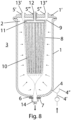
- the reference number 1 represents a pressure vessel which can be closed with a lid 1' and thereby forms a pressure vessel zone 2 in the interior of the pressure vessel, which is sealed from the external environment 3.
- At least one connector for a pressure line 4 in the container lid or preferably in the container jacket of the pressure vessel 1 can be used to load the inner pressure vessel zone 2 with pressure 4 'or to vent it with a vacuum 4".
- Located in the pressure vessel wall, preferably in the lid 1' There is at least one inlet 5', one outlet 5" and one filtrate drain connection 5"'. Another outlet 6 for the discharge of solids and liquids is preferably located in the lower area of the pressure vessel 1.
- a closure mechanism 7 is arranged adjacent to the discharge outlet 6.
- a flexible container is shown in an uninstalled and unfilled state.
- a flexible container wall 8 sealingly separates the inner area, the zone 9, from the external environment.
- One or more filter elements 10 are arranged inside the flexible container 8. Within these filter elements there are filtrate drain channels which are connected in a collecting piece 11. During filtration, the filtrate flows through the filter channels to the collecting piece and is discharged through the connected filtrate drain connection 12.
- the filtrate drain connection 12 leads through the flexible container wall 8 and is sealingly connected to it 8 '.
- the flexible container 8 preferably has at least two further connections 13 ', 13" in the upper region, which provide the inlet of the suspension, a rinsing liquid or gases into the inner zone 9 or the outlet of the suspension, a rinsing liquid or gases from the inner zone 9
- An extension 14, preferably in the lower region of the flexible container 8, serves to discharge solids and the discharge of unfiltered suspension from the inner zone 9.
- This discharge connection 14 can either be an extension of the flexible container 8 or from a container connected to the flexible container wall 8 flexible hose made of foil or elastic material.
- FIG. 3 shows the pressure vessel 1 with the installed flexible filtration vessel during the filling of the flexible filtration vessel 8 with suspension.
- the discharge connection 14 of the flexible container 8 is guided through the discharge connection 6 and seals the inner pressure vessel zone 2 from the external environment 3.
- the discharge connection 14 is sealed by the closure mechanism 7, which also sealingly separates the inner zone of the filtration container from the external environment 3.
- the two inlet and outlet connections 13', 13" of the filtration vessel 8 are guided through the inlet and outlet ports 5', 5" of the pressure vessel 1 and are also sealingly connected to the pressure vessel wall.
- the filtrate drain connection 12 of the filtration container is guided in a similar manner in a sealing manner through the filtrate drain connection 5'" of the pressure container.
- the inner zone 9 of the filtration container is filled with suspension through the inlet connection 13'.
- the inner zone 9 can be filled through the outlet connection 13" be vented.
- the suspension consists of a liquid 15 to be filtered with solids 16 to be separated.
- suspension can also be understood as a gas containing solids, the gas to be filtered being represented by the reference number 15 and the solid to be separated by the symbol 16.
- the inner pressure vessel zone 2 is vented through the connector 4 and 4", so that the flexible wall of the filtration vessel 8 can adapt to the contours of the pressure vessel 1 and is supported by it and limited in its further expansion.
- the flexible filtration container is installed in an evacuated form and is expanded and filled by applying a negative pressure in the nozzle 4 and thus between the pressure container wall 1 and the flexible container 8 (i.e. the inner pressure container zone 2).
- the suspension is filtered by applying a pressure gradient between the inner region 9 of the filtration container and the filtrate side 12.
- the pressure gradient is generated either by generating an excess pressure through the inlet connection 13' into the interior of the container 9 or by generating an underpressure in the filtrate outlet 12.
- the filtrate flows through the filter elements 10, is combined in the collecting piece 11 and discharged through the filtrate drain connection 12.
- the solid 16 collects on the filter elements 10.
- the connection 13" can can be used during filtration to remove suspension or to vent the inner zone 9.
- FIG. 5 Further residual volume filtration is in Figure 5 shown.
- An overpressure is introduced into the inner pressure vessel zone 2 through the nozzles 4 and 4', which compresses the flexible filtration vessel 8.
- the external force also presses out the individual filter elements 10 and the solid 16 collected thereon.
- the volumes between the filter elements 10 and within the filter elements themselves are reduced, and any remaining suspension in these volumes can therefore be removed better.
- the solid 16 can now be washed and/or dried with further rinsing liquids or gases introduced through the connections 13 'or 13".
- the suspension can pass through during the compression of the flexible container 8 the connections 13' and 13" are discharged.
- FIG 6 shows the regeneration of the filter elements 10 by rinsing off the solid 16.
- the solid 16 By backwashing the filter elements against the filtration direction, the solid 16 can be removed from the filter elements 10.
- filtrate, rinsing liquid or a gas is introduced into the inner zone 9 of the flexible container 8 through the filtrate drain connection 12 and the filter elements 10.
- the solid 16 is blown off and the filter elements 10 are now free again.
- the filtration cycle can now begin again ( Figure 3 ) or the concentrated solid can be emptied in the next step ( Figure 7 ).
- the solid can also be washed off by introducing liquid or gases through the connections 13 ', 13".
- the backwashing can also be carried out in the filled state, without the residual volume filtration ( Figure 5 ) be performed.
- the Solid 16 is washed away from the filter elements 10, which means that they are released again for new filtration.
- Figure 7 shows the discharge of the dry or concentrated solid 16 or the remaining suspension.
- the closure mechanism 7 is opened and the solid 16 or the residual liquid can escape through the discharge connection 14.
- the interior 9 of the filtration container and the filter elements 10 can be flushed by introducing liquid or gases through the connections 12, 13 'or 13".
- FIGS 9-11 show different versions of the closure mechanism 7 and the sealing of the inner pressure vessel zone 2 from the environment 3.
- the approaches shown are examples and can be carried out in any combinations.
- FIG 9 the pressure vessel 1 is shown.
- the flexible container 8 is equipped with an extension 14.
- this extension 14 is made of the same material as the flexible container 8, for example flexible plastic multilayer film.
- a bushing 6 is mounted in a wall of the pressure vessel 1. This is preferably located in the lower area.
- the flexible container 8 is installed in the pressure vessel 1, with the extension 14 being brought through the outlet 6 for the solids discharge.
- a closure mechanism 7 preferably a clamping device, particularly preferably a pinch valve, which allows the extension 14 of the filtration container to be closed tightly without coming into direct contact with the solid or suspension inside the container.
- the closure mechanism also seals the inner pressure vessel zone 2 from the environment 3 at least in the closed state, preferably also in the open state.
- Figure 10 shows another version of the discharge mechanism with the closure mechanism.
- a connecting piece 17 ' is sealingly attached to the flexible wall of the flexible container and is inserted into the discharge outlet 6 of the pressure vessel 1 when the flexible container is installed, the inner pressure vessel zone 2 being sealed by means of a seal 18', shown here as an O-ring the environment 3 is sealed.
- the extension 14, consisting of a film tube or a flexible tube material, for example silicone, is sealingly connected to the connecting piece 17 'and leads through a subsequent clamping device 7'.
- this is represented by a membrane body, which applies a pressing force to the extension 14 by applying pressure and closes it.
- direct contact between the valve and the solid or liquid in the flexible container is prevented, which has advantages for sterile operation.
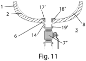
- Figure 11 shows a further variant with a flat gasket 18" as a seal of the connecting piece 17' to the pressure vessel 1.
- the extension 14 of the flexible container 8 is provided at its end with a further connection 19', which is connected to a valve 7", for example to a ball valve can be connected.
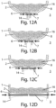
- Figures 12 and 13 show variants of the invention with a locking mechanism 7 in different sizes when closed ( Figure 12A-D ) and in the open state ( Figure 13A-D ).
- discharge is difficult, especially if the opening of the outlet for the solids discharge 6 or of the discharge connection 14 is very small. If the discharge diameter is too small, there is a risk that the solid or Solid sludge 16 flows unfavorably or not at all or the discharge connection 14 becomes clogged.
- a diameter adapted to the solids must therefore be selected for the discharge nozzle 6, the closure mechanism 7 and for the discharge connection 14 (in the open state).
- FIG 14A a variant of the invention with a side outlet 6 for the solids discharge and discharge connection 14 is shown.
- the solid 16 is emptied by opening the closure mechanism 7 ( Figure 14B ).
- the flexible container 8 can be compressed by applying pressure in the zone 2 through the connection 4, which promotes the complete discharge of the solid or the solid sludge 16.
Claims (17)
- Dispositif, destiné à séparer des matières solides de liquides ou de gaz, comprenant un réservoir sous pression (1), pourvu d'au moins une tubulure d'entrée (5') pour un raccord d'entrée (13'), d'au moins une tubulure d'écoulement (5''') du filtrat pour un raccord d'écoulement (12) du filtrat, et de plusieurs éléments filtrants (10), les éléments filtrants (10) étant placés en parallèle côte à côte et étant assemblés les uns avec les autres en un bloc filtrant, entre les éléments filtrants (10) individuels, un espace libre restant ménagé sur une majeure partie de leur extension longitudinale verticale et les éléments filtrants (10) étant placés dans un réservoir (8) souple, qui est placé dans le réservoir sous pression (1) et fermé de manière étanche par rapport à celui-ci, le réservoir sous pression (1) comprenant au moins une sortie (6) pour l'évacuation des matières solides et le réservoir (8) souple comprenant au moins un raccord d'évacuation (14), le raccord d'évacuation (14) du réservoir (8) souple étant tiré à travers la sortie (6) du réservoir sous pression (1) et fermé de manière étanche par rapport au réservoir sous pression (1), la sortie (6) et le raccord d'évacuation (14) du réservoir (8) souple étant susceptibles d'être fermés de manière à assurer l'étanchéité par rapport à l'environnement (3) au moyen d'un mécanisme de fermeture (7, 7', 7") à l'extérieur du réservoir (8) souple et du réservoir sous pression (1), caractérisé en ce que les éléments filtrants (10) sont conçus de telle sorte, que pour vider le réservoir (8) souple, ils soient compressibles les uns contre les autres, à l'intérieur du réservoir sous pression (1), entre la paroi intérieure du réservoir sous pression et la paroi extérieure du réservoir (8) souple se trouvant une zone (2) de réservoir sous pression étanchéifiée et sur le réservoir sous pression (1) étant montée une conduite sous pression (4), pour introduire une surpression dans la zone (2) de réservoir sous pression à l'intérieur du réservoir sous pression (1), pour comprimer le réservoir (8) souple et compresser les uns contre les autres les éléments filtrants (10) dans le réservoir (8) souple.
- Dispositif selon la revendication 1, caractérisé en ce que le mécanisme de fermeture (7) est un dispositif de serrage.
- Dispositif selon la revendication 1, caractérisé en ce que le mécanisme de fermeture (7) est un cylindre de fermeture.
- Dispositif selon l'une quelconque des revendications précédentes, caractérisé en ce que l'étanchéité entre le raccord d'évacuation (14) du réservoir (8) souple et la sortie (6) du réservoir sous pression (1) est assurée au moyen d'un joint.
- Dispositif selon la revendication 4, caractérisé en ce que le joint est une bague torique ou un joint plat.
- Dispositif selon l'une quelconque des revendications précédentes, caractérisé en ce que le diamètre de la sortie (6) pour l'évacuation des matières solides est d'au moins 15 mm, notamment d'au moins 20 mm, de préférence d'au moins 25 mm.
- Dispositif selon la revendication 6, caractérisé en ce que le diamètre de la sortie (6) pour l'évacuation des matières solides est de même dimension que le diamètre du réservoir sous pression (1).
- Dispositif selon l'une quelconque des revendications précédentes, caractérisé en ce que les éléments filtrants (10) sont placés en étant suspendus.
- Dispositif selon l'une quelconque des revendications précédentes, caractérisé en ce que les éléments filtrants (10) placés côte à côte à la parallèle sont conçus chacun sous forme plate.
- Dispositif selon l'une quelconque des revendications 1 à 8, caractérisé en ce que les éléments filtrants (10) sont conçus sous forme ronde.
- Dispositif selon l'une quelconque des revendications précédentes, caractérisé en ce que le réservoir (8) souple peut se retirer du réservoir sous pression (1).
- Dispositif selon l'une quelconque des revendications précédentes, caractérisé en ce que l'au moins une sortie (6) pour l'évacuation des matières solides et le raccord d'évacuation (14) du réservoir (8) souple sont placés dans la zone inférieure du réservoir sous pression (1) et du réservoir (8) souple.
- Dispositif selon l'une quelconque des revendications précédentes, caractérisé en ce que le réservoir (8) souple comporte des raccords d'entrée et de sortie (13', 13") et en ce qu'à l'intérieur du réservoir (8) souple, les raccords d'entrée et de sortie (13', 13") sont munis d'un flexible.
- Dispositif selon la revendication 13, caractérisé en ce que l'extrémité du flexible sur le réservoir (8) souple est munie d'une buse.
- Utilisation du dispositif selon l'une quelconque des revendications précédentes pour filtrer des matières solides hors de liquides ou de gaz et pour évacuer les matières solides du dispositif.
- Procédé, destiné à filtrer des matières solides hors de liquides ou de gaz, et à évacuer les matières solides au moyen du dispositif selon l'une quelconque des revendications 1 à 14, comprenant les étapes consistant àa) appliquer une pression différentielle entre l'espace intérieur du réservoir (8) souple et l'écoulement du filtrat,b) remplir le réservoir (8) souple d'une suspension ou d'un gaz,c) appliquer une dépression dans l'écoulement de filtrat ou une surpression dans le réservoir (8) souple,d) presser le réservoir (8) souple,e) rincer les matières solides avec des liquides de rinçage ou des gaz à travers le raccord d'entrée (13'),f) éliminer par rinçage les matières solides des éléments filtrants (10) à travers le raccord d'écoulement (12) du filtrat, pour régénérer les éléments filtrants (10) pour le cycle suivant,g) ouvrir le mécanisme de fermeture (7, 7', 7") et évacuer les matières solides à travers le raccord d'évacuation (14) du réservoir (8) souple sur la sortie (6) du réservoir sous pression (1).
- Procédé selon la revendication 16, caractérisé en ce que les étapes a) à g) sont répétées une ou plusieurs fois.
Applications Claiming Priority (2)
| Application Number | Priority Date | Filing Date | Title |
|---|---|---|---|
| CH00902/18A CH715193A1 (de) | 2018-07-23 | 2018-07-23 | Vorrichtung zur Abtrennung von Feststoffen aus Flüssigkeiten und Gasen. |
| PCT/IB2019/055670 WO2020021363A1 (fr) | 2018-07-23 | 2019-07-03 | Dispositif de séparation de matières solides de liquides et de gaz |
Publications (3)
| Publication Number | Publication Date |
|---|---|
| EP3826749A1 EP3826749A1 (fr) | 2021-06-02 |
| EP3826749B1 true EP3826749B1 (fr) | 2023-09-20 |
| EP3826749C0 EP3826749C0 (fr) | 2023-09-20 |
Family
ID=67928861
Family Applications (1)
| Application Number | Title | Priority Date | Filing Date |
|---|---|---|---|
| EP19766355.2A Active EP3826749B1 (fr) | 2018-07-23 | 2019-07-03 | Dispositif de séparation de matières solides de liquides et de gaz |
Country Status (7)
| Country | Link |
|---|---|
| US (1) | US20220008846A1 (fr) |
| EP (1) | EP3826749B1 (fr) |
| JP (1) | JP7152809B2 (fr) |
| KR (1) | KR102624840B1 (fr) |
| CN (1) | CN112512660B (fr) |
| CH (1) | CH715193A1 (fr) |
| WO (1) | WO2020021363A1 (fr) |
Citations (1)
| Publication number | Priority date | Publication date | Assignee | Title |
|---|---|---|---|---|
| EP0555740A1 (fr) * | 1992-02-14 | 1993-08-18 | BASF Magnetics GmbH | Installation de filtrage |
Family Cites Families (14)
| Publication number | Priority date | Publication date | Assignee | Title |
|---|---|---|---|---|
| US1721250A (en) * | 1923-11-27 | 1929-07-16 | Ernest J Sweetland | Filter |
| FR2504113B2 (fr) * | 1980-09-11 | 1986-04-11 | Electricite De France | Dispositif perfectionne d'epuration electrolytique des eaux residuaires |
| DE3807828C2 (de) | 1988-03-10 | 1997-01-16 | Cuno Inc | Vorrichtung für eine Filtervorrichtung |
| JPH0453407U (fr) * | 1990-09-07 | 1992-05-07 | ||
| DE9307195U1 (fr) * | 1993-05-12 | 1993-07-15 | Basf Magnetics Gmbh, 6800 Mannheim, De | |
| JP3679584B2 (ja) * | 1997-12-05 | 2005-08-03 | 株式会社ティーディーイー | チューブプレス |
| JP3956370B2 (ja) * | 2004-03-25 | 2007-08-08 | 月島機械株式会社 | スラリーの脱水方法およびフィルタープレス装置 |
| JP4811837B2 (ja) * | 2008-07-04 | 2011-11-09 | スティーゲブラント ヒドロテクニック アーベー | 脱水装置 |
| US9675914B2 (en) * | 2009-04-16 | 2017-06-13 | Bha Altair, Llc | Bagged filter cartridge, system and methods |
| EP2283907A1 (fr) | 2009-08-11 | 2011-02-16 | Koninklijke Philips Electronics N.V. | Ensemble de purification de fluides comprenant une partie fonctionnelle et un boîtier |
| EP2407226A1 (fr) | 2010-07-16 | 2012-01-18 | Filtrox AG | Module de filtration pour l'utilisation unique, ainsi que procédé de fabrication et d'utilisation d'un tel module de filtration |
| CH705313A1 (de) * | 2011-07-28 | 2013-01-31 | Mueller Drm Ag | Vorrichtung zur Abtrennung von Feststoffpartikeln aus Flüssigkeiten und deren Anwendung. |
| CN107774038A (zh) * | 2016-08-30 | 2018-03-09 | 江苏吉华化工有限公司 | 一种化工用过滤装置 |
| CH713395A1 (de) * | 2017-01-30 | 2018-07-31 | Mueller Drm Ag | Vorrichtung zur Abtrennung von Feststoffpartikeln aus Flüssigkeiten und Gasen. |
-
2018
- 2018-07-23 CH CH00902/18A patent/CH715193A1/de unknown
-
2019
- 2019-07-03 JP JP2021503017A patent/JP7152809B2/ja active Active
- 2019-07-03 CN CN201980048313.5A patent/CN112512660B/zh active Active
- 2019-07-03 KR KR1020217002082A patent/KR102624840B1/ko active IP Right Grant
- 2019-07-03 US US17/260,176 patent/US20220008846A1/en active Pending
- 2019-07-03 WO PCT/IB2019/055670 patent/WO2020021363A1/fr unknown
- 2019-07-03 EP EP19766355.2A patent/EP3826749B1/fr active Active
Patent Citations (1)
| Publication number | Priority date | Publication date | Assignee | Title |
|---|---|---|---|---|
| EP0555740A1 (fr) * | 1992-02-14 | 1993-08-18 | BASF Magnetics GmbH | Installation de filtrage |
Also Published As
| Publication number | Publication date |
|---|---|
| KR20210024058A (ko) | 2021-03-04 |
| JP2021531160A (ja) | 2021-11-18 |
| EP3826749A1 (fr) | 2021-06-02 |
| JP7152809B2 (ja) | 2022-10-13 |
| CH715193A1 (de) | 2020-01-31 |
| WO2020021363A1 (fr) | 2020-01-30 |
| US20220008846A1 (en) | 2022-01-13 |
| EP3826749C0 (fr) | 2023-09-20 |
| CN112512660A (zh) | 2021-03-16 |
| CN112512660B (zh) | 2023-02-21 |
| KR102624840B1 (ko) | 2024-01-12 |
Similar Documents
| Publication | Publication Date | Title |
|---|---|---|
| EP3573738B1 (fr) | Dispositif destiné à la séparation de particules solides à partir de liquides et de gaz | |
| EP1965889B1 (fr) | Systeme d'epuration de gaz | |
| EP0555740B1 (fr) | Installation de filtrage | |
| EP1154838A1 (fr) | Ensemble filtrant pour filtration sous vide | |
| EP0577854B1 (fr) | Dispositif de filtration | |
| EP3826749B1 (fr) | Dispositif de séparation de matières solides de liquides et de gaz | |
| DE2549040C3 (de) | Auspreßfilter | |
| DE19857751A1 (de) | Modulfilter mit zumindest einem Zulauf für Unfiltrat und einem Ablauf für das Filtrat und mit zumindest einem Filtermodul | |
| EP2156745B1 (fr) | Agencement de récipient sous pression comprenant un récipient sous pression extérieur et au moins un panier d'insertion | |
| DE202006004529U1 (de) | Filtereinsatz mit Verschluss für zweite Filterkammer | |
| EP3793706B1 (fr) | Filtre d'aspiration | |
| DE4300493C2 (de) | Verfahren zum Schlammabschneiden | |
| EP0645446B1 (fr) | Dispositif pour recueillir les agents stabilisant des boissons ou d'autres liquides | |
| DE4336870C2 (de) | Filterpatrone | |
| DE2461778C2 (de) | Vorrichtung zum Filtrieren von Flüssigkeiten | |
| DE3909382A1 (de) | Filterelement | |
| EP0668478A1 (fr) | Récipient avec dispositif agitateur | |
| DE3605065A1 (de) | Separationsvorrichtung | |
| DE102009018934A1 (de) | Druckfiltervorrichtung und Verfahren zur Filtration | |
| WO1991008035A1 (fr) | Dispositif de deshydratation de boues | |
| EP1080768A1 (fr) | Filtre sous pression pouvent facile à nettoyer | |
| JPH0323294Y2 (fr) | ||
| EP1946814B1 (fr) | Procédé et dispositif destinés à la filtration avec rétrolavage | |
| EP3962628A1 (fr) | Élément d'étanchéité | |
| EP0766987A1 (fr) | Tamis-corbeille avec sac filtrant et le boîtier |
Legal Events
| Date | Code | Title | Description |
|---|---|---|---|
| STAA | Information on the status of an ep patent application or granted ep patent |
Free format text: STATUS: UNKNOWN |
|
| STAA | Information on the status of an ep patent application or granted ep patent |
Free format text: STATUS: THE INTERNATIONAL PUBLICATION HAS BEEN MADE |
|
| STAA | Information on the status of an ep patent application or granted ep patent |
Free format text: STATUS: THE INTERNATIONAL PUBLICATION HAS BEEN MADE |
|
| PUAI | Public reference made under article 153(3) epc to a published international application that has entered the european phase |
Free format text: ORIGINAL CODE: 0009012 |
|
| STAA | Information on the status of an ep patent application or granted ep patent |
Free format text: STATUS: REQUEST FOR EXAMINATION WAS MADE |
|
| 17P | Request for examination filed |
Effective date: 20210122 |
|
| AK | Designated contracting states |
Kind code of ref document: A1 Designated state(s): AL AT BE BG CH CY CZ DE DK EE ES FI FR GB GR HR HU IE IS IT LI LT LU LV MC MK MT NL NO PL PT RO RS SE SI SK SM TR |
|
| DAV | Request for validation of the european patent (deleted) | ||
| DAX | Request for extension of the european patent (deleted) | ||
| STAA | Information on the status of an ep patent application or granted ep patent |
Free format text: STATUS: EXAMINATION IS IN PROGRESS |
|
| 17Q | First examination report despatched |
Effective date: 20220224 |
|
| GRAP | Despatch of communication of intention to grant a patent |
Free format text: ORIGINAL CODE: EPIDOSNIGR1 |
|
| STAA | Information on the status of an ep patent application or granted ep patent |
Free format text: STATUS: GRANT OF PATENT IS INTENDED |
|
| INTG | Intention to grant announced |
Effective date: 20230421 |
|
| GRAS | Grant fee paid |
Free format text: ORIGINAL CODE: EPIDOSNIGR3 |
|
| GRAA | (expected) grant |
Free format text: ORIGINAL CODE: 0009210 |
|
| STAA | Information on the status of an ep patent application or granted ep patent |
Free format text: STATUS: THE PATENT HAS BEEN GRANTED |
|
| AK | Designated contracting states |
Kind code of ref document: B1 Designated state(s): AL AT BE BG CH CY CZ DE DK EE ES FI FR GB GR HR HU IE IS IT LI LT LU LV MC MK MT NL NO PL PT RO RS SE SI SK SM TR |
|
| REG | Reference to a national code |
Ref country code: GB Ref legal event code: FG4D Free format text: NOT ENGLISH |
|
| REG | Reference to a national code |
Ref country code: CH Ref legal event code: EP |
|
| REG | Reference to a national code |
Ref country code: IE Ref legal event code: FG4D Free format text: LANGUAGE OF EP DOCUMENT: GERMAN |
|
| REG | Reference to a national code |
Ref country code: DE Ref legal event code: R096 Ref document number: 502019009426 Country of ref document: DE |
|
| U01 | Request for unitary effect filed |
Effective date: 20230925 |
|
| U07 | Unitary effect registered |
Designated state(s): AT BE BG DE DK EE FI FR IT LT LU LV MT NL PT SE SI Effective date: 20230929 |
|
| PG25 | Lapsed in a contracting state [announced via postgrant information from national office to epo] |
Ref country code: GR Free format text: LAPSE BECAUSE OF FAILURE TO SUBMIT A TRANSLATION OF THE DESCRIPTION OR TO PAY THE FEE WITHIN THE PRESCRIBED TIME-LIMIT Effective date: 20231221 |
|
| PG25 | Lapsed in a contracting state [announced via postgrant information from national office to epo] |
Ref country code: RS Free format text: LAPSE BECAUSE OF FAILURE TO SUBMIT A TRANSLATION OF THE DESCRIPTION OR TO PAY THE FEE WITHIN THE PRESCRIBED TIME-LIMIT Effective date: 20230920 Ref country code: NO Free format text: LAPSE BECAUSE OF FAILURE TO SUBMIT A TRANSLATION OF THE DESCRIPTION OR TO PAY THE FEE WITHIN THE PRESCRIBED TIME-LIMIT Effective date: 20231220 Ref country code: HR Free format text: LAPSE BECAUSE OF FAILURE TO SUBMIT A TRANSLATION OF THE DESCRIPTION OR TO PAY THE FEE WITHIN THE PRESCRIBED TIME-LIMIT Effective date: 20230920 Ref country code: GR Free format text: LAPSE BECAUSE OF FAILURE TO SUBMIT A TRANSLATION OF THE DESCRIPTION OR TO PAY THE FEE WITHIN THE PRESCRIBED TIME-LIMIT Effective date: 20231221 |
|
| PG25 | Lapsed in a contracting state [announced via postgrant information from national office to epo] |
Ref country code: IS Free format text: LAPSE BECAUSE OF FAILURE TO SUBMIT A TRANSLATION OF THE DESCRIPTION OR TO PAY THE FEE WITHIN THE PRESCRIBED TIME-LIMIT Effective date: 20240120 |