EP3825641A1 - Magazin für feuerwaffen - Google Patents
Magazin für feuerwaffen Download PDFInfo
- Publication number
- EP3825641A1 EP3825641A1 EP19210900.7A EP19210900A EP3825641A1 EP 3825641 A1 EP3825641 A1 EP 3825641A1 EP 19210900 A EP19210900 A EP 19210900A EP 3825641 A1 EP3825641 A1 EP 3825641A1
- Authority
- EP
- European Patent Office
- Prior art keywords
- magazine
- slide
- magazine according
- designed
- loading aid
- Prior art date
- Legal status (The legal status is an assumption and is not a legal conclusion. Google has not performed a legal analysis and makes no representation as to the accuracy of the status listed.)
- Granted
Links
Images




Classifications
-
- F—MECHANICAL ENGINEERING; LIGHTING; HEATING; WEAPONS; BLASTING
- F41—WEAPONS
- F41A—FUNCTIONAL FEATURES OR DETAILS COMMON TO BOTH SMALLARMS AND ORDNANCE, e.g. CANNONS; MOUNTINGS FOR SMALLARMS OR ORDNANCE
- F41A9/00—Feeding or loading of ammunition; Magazines; Guiding means for the extracting of cartridges
- F41A9/61—Magazines
- F41A9/64—Magazines for unbelted ammunition
- F41A9/65—Box magazines having a cartridge follower
- F41A9/66—Arrangements thereon for charging, i.e. reloading
- F41A9/67—Arrangements thereon for charging, i.e. reloading having means for depressing the cartridge follower, or for locking it in a depressed position
-
- F—MECHANICAL ENGINEERING; LIGHTING; HEATING; WEAPONS; BLASTING
- F41—WEAPONS
- F41A—FUNCTIONAL FEATURES OR DETAILS COMMON TO BOTH SMALLARMS AND ORDNANCE, e.g. CANNONS; MOUNTINGS FOR SMALLARMS OR ORDNANCE
- F41A9/00—Feeding or loading of ammunition; Magazines; Guiding means for the extracting of cartridges
- F41A9/01—Feeding of unbelted ammunition
- F41A9/06—Feeding of unbelted ammunition using cyclically moving conveyors, i.e. conveyors having ammunition pusher or carrier elements which are emptied or disengaged from the ammunition during the return stroke
- F41A9/07—Reciprocating conveyors, i.e. conveyors pushing a plurality of ammunition during the feeding stroke
-
- F—MECHANICAL ENGINEERING; LIGHTING; HEATING; WEAPONS; BLASTING
- F41—WEAPONS
- F41A—FUNCTIONAL FEATURES OR DETAILS COMMON TO BOTH SMALLARMS AND ORDNANCE, e.g. CANNONS; MOUNTINGS FOR SMALLARMS OR ORDNANCE
- F41A9/00—Feeding or loading of ammunition; Magazines; Guiding means for the extracting of cartridges
- F41A9/61—Magazines
- F41A9/62—Magazines having means for indicating the number of cartridges left in the magazine, e.g. last-round indicators
Definitions
- the invention relates to an improved magazine for firearms, which comprises a dismountable loading aid, which can be installed easily, without tools and without loss, and which can be easily removed from the magazine with the aid of a simple tool, according to the preamble of claim 1.
- the magazine according to the invention is a modification of known magazines for, for example, pistols and other firearms.
- the improvements are achievable by the achievable effects or advantages as set out below.
- “Lateral surfaces” are both left and right surfaces between the front and rear ends, viewed in the direction of the mouth.
- the terms “magazine”, “feeder”, “magazine base”, “magazine plate”, etc. have the usual meaning that the person skilled in the art attaches to them in the prior art. Areas “parallel” to an axis form cylindrical outer surfaces, “recesses” relate to the surrounding areas of the object under consideration, etc.
- the cartridge can be fed using a magazine, for example.
- a magazine for example.
- Common magazine shapes for semi and fully automatic firearms are e.g. the box magazine, rod magazine and curve magazine.
- a magazine usually comprises an elongated body with a largely rectangular cross-section. At the upper end there are magazine lips and an opening to be able to transport the topmost cartridge into the hold of a firearm. At the lower end there is a magazine base, which with is connected to the magazine body. In the magazine body, between the upper and lower end, there is a feeder, viewed from above, which is connected to a magazine spring, the magazine spring being connected to the magazine floor directly or by means of a base plate.
- the spring force of the spring pushes the feeder upwards, when the magazine is empty up to the magazine lips.
- cartridges are pushed into the magazine from above through the opening in such a way that the feeder is pushed down a little against the spring force.
- the spring is pretensioned more strongly with each additional cartridge pushed into the magazine, consequently more and more downward pressure is required to push the next cartridge into the magazine.
- the filling of the magazine is also made more difficult by the possible slipping of the round cartridge case from one another, and the conical designs towards the cartridge tip and, in the case of rimfire cartridges, the larger diameter of the cartridge base compared to the case, make it more difficult.
- the conventional filling of a magazine with cartridges is correspondingly difficult, in particular the more a magazine is already filled. Filling accordingly requires time, skill and strength.
- the prior art has accordingly known for a long time loading aids that make it easier to fill magazines with cartridges.
- the US 9,846,004 B2 and the US 2018/231 339 A1 for example each disclose a magazine with a slot in one of the side walls and a feeder with an opening at which a tool can be attached to one side of the magazine in order to push the feeder downwards.
- the one-sided application of the tool has a disadvantageous effect, since it is possible for the feeder to tilt and get stuck when it is pushed down.
- Another disadvantage is that the loading aid is only created in combination: "Magazine with tool", that is, a separate tool is required.
- the US 2019/219 352 A1 shows a magazine with a side slot and a button attached to one side of the feeder and protruding over the magazine body, by means of which the feeder can be pushed down. By the one-sided If the button is attached, it is possible for the feeder to tilt and get stuck. Another disadvantage is the fact that the button is not flush with the magazine body. Such a loading aid standing over the magazine body and firmly connected to the feeder is also used in the US 2016/003 568 A1 shown. A loading aid that extends beyond the magazine body cannot easily be inserted into the magazine slot of a firearm; special designs are necessary which, for example, require more space and material and / or result in heavier magazines.
- the GB 110577 A shows a magazine with a slot on both sides and a loading aid which is attached to the magazine by means of a thread and can be operated from both sides.
- the necessary complex production of the thread as well as the lack of protection against loss have a disadvantage.
- the object of the present invention is to avoid the disadvantages mentioned in the prior art and to provide a magazine with a loss-proof, easily dismantled loading aid.
- a further object for refinements of the invention is to provide an optimized, operationally reliable magazine and to make the loading status of the magazine easily recognizable even when there is no visual contact.
- a magazine of the type mentioned at the beginning has the features specified in the characterizing part of claim 1.
- the magazine comprises a slot on each side wall, a feeder with a slide receptacle and a loading aid, the loading aid comprising a first and a second slide which can be coupled within the slide receptacle by means of at least one latch.
- the at least one catch At least one hole is provided on the feeder as a dismantling opening.
- the solution according to the invention creates a magazine with a loading aid that is secured against loss but nevertheless easily dismantled.
- the loading aid is vertical over the entire length slidable area behind the contour of the magazine body receding to a maximum of flush. This means that the magazine can also be used in a firearm with a built-in loading aid without disruption and avoiding loading jams.
- the loading aid can be brought into a dismantling position through the dismantling opening / hole with the aid of a simple tool such as a dismantling pin, by means of light pressure on at least one locking projection and then dismantled.
- the loading aid has two slides that can be inserted into one another.
- the slides are designed to be complementary in shape to one another, with a pin receptacle and slide pin. This means that the loading aid can easily be installed in the assembled magazine; it is only necessary to insert the first and second slider into the slider receptacle and to press the slider together with your fingers, for example.
- an opening which starts from the bolt receptacle and is connected to the hole in the installed state, on which a stop surface and a support surface are formed.
- the stop surface is preferably closer to the second handle than the support surface.
- an extension is formed with a protrusion protruding in the radial direction, which forms a catch and an end surface, the catch being closer to the first handle than the end surface.
- the projection is designed in a shape complementary to the opening and preferably points downwards.
- the advantage of this embodiment is that the detent of the first slide interacts with the support surface of the second slide and prevents a relative movement of the first slide away from the second slide in the axial direction of the second slide pin. Furthermore, the end face of the first slide cooperates with the stop face of the second slide and prevents the relative movement in the axial direction of the second slide pin, the first slide and the second slide to one another. When installed, the two slides of the loading aid are firmly connected to one another.
- the extension can be deflected elastically relative to the first slide pin in the direction of a dismantling position.
- the extension with the projection forming the detent is free of the support surface, which enables the two slides to be pushed apart axially.
- the feeder has a dismantling opening designed as a hole, which makes the opening and thus the projection accessible.
- An action of force, essentially normal to the axis of the second slide pin, on the projection releases the catch from the support surface and thus defines a dismantling position.
- Such a hole offers the advantage that pressure can be easily exerted on the projection using a simple tool such as a cutting pin in order to free the detent, which means that the loading aid can also be dismantled on the assembled magazine without any problems.
- the loading aid is dismantled after pressure is exerted on the projection by pulling the two handles slightly apart.
- An embodiment is advantageous in which, on the first and / or second handle, first and / or second side surfaces on a groove side of the groove and a first and / or second inner surface on a groove bottom of the groove are designed with a complementary shape.
- the first and second side surfaces can interact with the groove side or first and second inner surfaces with the groove bottom and be guided by them.
- This guide stabilizes the alignment of the feeder in the x, y and z axes (x-axis: front / back; y-axis: left / right and z-axis: vertical or in the direction of the magazine axis and thus essentially parallel to the slot) and thus works against tilting.
- the slide receptacle prefferably be designed to complement the shape of the first slide pin.
- the complementary design favors a firm fit of the loading aid in the slide mount.
- a slide bolt designed as a circle in cross section is advantageous, since such a design is advantageous in terms of production technology and any forces that may occur in the material can be dissipated particularly well.
- a further advantageous embodiment is an elongated shape with two parallel longitudinal surfaces, which is the same as an elongated hole in the cross section of the second slide bolt and the slide receptacle. These parallel longitudinal surfaces interact with the slot side, the feeder is thereby additionally guided during vertical movement and the anti-tilting effect is reinforced.
- the cross section of the second slide pin and the slide receptacle have an end face. This end face can prevent the loading aid from being installed in the wrong orientation, that is to say with the projection pointing away from the hole.
- a further advantageous embodiment has an asymmetry element somewhere on the cross-section of the second slide pin and the slide receptacle, which due to its shape only allows precisely one orientation for the installation of the loading aid in the magazine. Installation in the wrong orientation, e.g. with an indicator pointing away from the charge level display, can be prevented.
- a first indicator can be arranged on the first slide and / or a second indicator is arranged on the second slide and a charge level indicator is arranged on the magazine body, preferably on the side.
- the indicator and / or charge level display can be designed optically, in particular luminescent and / or haptically perceptible, e.g. by means of a notch, recess and / or elevation.
- the advantage of such an embodiment is that the user can visually perceive the charge status of the magazine immediately and easily. With the luminescent design, optical perception is also possible in the dark. The haptic design allows the charge level to be recognized by touch, even without visual contact.
- the gripping surface of the first and / or second handle can be designed to be non-slip and to have at least one anti-slip notch.
- the advantage here is that the feeder can be pushed down slightly against the spring force to fill the magazine, and also in low-friction, slippery conditions, e.g. hot, humid weather and perspiration or possible contamination of the hands and / or the loading aid with lubricating or oily substances a safe and trouble-free pushing of the feeder down without slipping is possible and thus easy filling of the magazine.
- slippery conditions e.g. hot, humid weather and perspiration or possible contamination of the hands and / or the loading aid with lubricating or oily substances
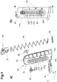
- the Fig. 1a shows an exemplary embodiment of a magazine 10 according to the invention as an exploded view.
- the magazine 10 comprises a magazine body 11 which is elongated in the vertical direction and has a substantially rectangular cross-section in the vertical direction and thus a narrower front surface 111 ( Figure 1b ), a narrower rear surface 113, two wider sides 112, and an upper and a lower end.
- the magazine 10 comprises a magazine base 14 attached to the lower end of the magazine body 11, a magazine plate 15 cooperating with the magazine base 14, lips 13 located at the upper end, a spring 16 and a feeder 20 also located at the upper end In the assembled state of the magazine, it is connected at one end to the feeder 20 and at the other end to the magazine base 14 by means of the magazine plate 15.
- the feeder 20 is pressed upward in the direction of the lips 15 by the spring force. When the cartridge is full, the next cartridge is transported upwards after the top cartridge has been removed.
- the magazine 10 is filled by inserting cartridges into the magazine from above by exerting pressure on the feeder 20 against the force of the spring 16.
- the magazine body 11 has on its sides 112 an elongated slot 120 oriented essentially in the vertical direction, which ends at a distance from both the bottom 14 and the lips 13, so that the magazine body 11 is continuous on its sides 113 at the top and bottom
- the magazine body 11 has on its Sides 112 along the slot 120 a groove 170 with groove bottom 171 and groove side 172, wherein the groove bottom 171 is essentially parallel and the groove side 172 is essentially normal to the side 112.
- the dismountable loading aid consists of a first slide 30 and a second slide 40 and, when installed, is arranged in a slide mount 21 of the feeder 20. In the installed state, the assembled loading aid penetrates the magazine body 11 at the slot 120 and is recessed or flush with the sides 112.
- the loading aid is moved against the force of the spring 16 in the slot 120, the filling of the magazine 10 with cartridges being facilitated by the feeder 20 pressed down with the loading aid.
- the Figure 1b represents the magazine of the Fig. 1a in a side view.
- the charge level indicator 19 as well as the width B1 of the slot 120 and the width B2 of the groove 170 are clearly visible.
- the Fig. 2 shows the feeder 20 with the loading aid in an axial exploded view.
- the support surface 23 which is in contact with the bottom cartridge when the magazine 10 is full.
- the spring receptacle 25 which is arranged on the neck 22 and on which the spring is connected to the feeder 20, can also be seen.
- the loading aid consisting of the first and the second slide 30 and 40 is arranged in the slide receptacle 21.
- the first slide 30 has a first slide pin 31 with an extension 34 and a projection 37.
- the second slide 40 has a second slide pin 41 with an opening 45, a second handle 420, and an optional second indicator 43.
- the optional second indicator 43 is shown by way of example in the form of an arrow.
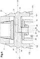
- FIG. 4 shows a section along the line IV-IV of FIG Figure 1b the loading aid in the disassembled state, without the surrounding components, the Fig. 4 the same section in the installed state with the surrounding components.
- the first slide pin 31 is complementary in shape to the pin recess 44 and can be received by this.
- the extension 34 with the projection 37, the detent 36 and the end surface 38 are shaped complementary to the bolt recess 44 with the opening 45.
- the bolt recess 44 preferably has a taper 47, a support surface 46 and a stop surface 48.
- the extension 34 of the first slide 30 is inserted into the bolt recess 44 of the second slide in the axial direction of the second slide bolt (in Fig. 4 labeled VI), the projection 37 in the direction of the hole 24, in the example shown in FIG Fig. 4 down, oriented.
- the extension 34 is designed to be elastically deformable relative to the first slide pin 31, which enables a simple assembly or dismantling process.
- the slides 30 and 40 together in the axial direction VI they are moved relative to one another and the first slide 30 is pressed into the second slide 40.
- the further the first and second slides 30 and 40 are moved into one another the more the extension 34 is deflected upwards according to the principle of a leaf spring. If the extension 34 with projection 37 completely reaches the opening 45, extension 34 springs back into its original position.
- the coupling takes place by engaging the projection 37 or its catch 36 on the support surface 46 of the opening 45.
- the end face 38 abuts the stop face 48 at the same time, as a result of which both an axial and a rotating movement of the first slide 30 relative to the second slide 40 is prevented.
- the loading aid To dismantle the loading aid, pressure is exerted on the projection 37 from below and this is pressed out of the opening 45 by elastic deformation.
- the support surface 46 releases the catch 36 and the first slide 30 can be moved out of the second slide 40 in the axial direction.
- the special shape of the bending groove 35 (in the manner of a tapering of the cross-sectional area) supports this process, since this enables and / or facilitates a resilient deflection of the extension 34 upwards.
- the dismantling position is thus achieved in that the action of a force essentially normal to the axis of the second slide pin 41 through the hole 24 on the projection 37 releases the detent 36 from the support surface 46.
- the feeder 20 has a hole 24 in order to enable access by means of a simple tool such as, for example, a cutting pin, to the projection 37 and thus to enable the loading aid to be dismantled in the installed state in the magazine 10. Designs with at least two notches 36 formed on the loading aid are also possible.
- the feeder 20 then has a corresponding number of holes 24 in order to make the catches 36 accessible and to enable the dismantling process.
- first and second handles 330 and 430 lie completely in the groove 170 of the slot 120 and are flush with the sides 112 of the magazine body 11. Is particularly good in Fig. 3 an upwardly inwardly tapered and thus slightly triangular cross-section of the first and second handles 320 and 420 can be seen, which is designed in accordance with the shape of the magazine body, which is slightly tapered at the upper end.
- the first and second handles 320 and 420 are flush with the magazine body 11 even when they are in the upper end region of the magazine 10, and the loading aid is freely movable over the full length of the slot 120 from this side even when the magazine 10 is pushed into the magazine well .
- the handles 320 and 420 are shown stretched in the vertical direction and each have two first and second side surfaces 322 and 422 that run at least approximately parallel to one another and vertically.
- the normal distance between the two first side surfaces 322 and the two second side surfaces 422 from one another corresponds to the width B2 of the groove 170 (shown in FIG Figure 1b ).
- both handles 320, 420 are guided in the respective associated groove 170 on the associated side 112 of the magazine 10, the respectively parallel first and second side surfaces 322 and 422 also being aligned parallel to the respective groove 170.
- the groove side 172 corresponding to the first and / or second handle 320, 420 guides the side surfaces 322, 422, wherein the inner surfaces 323, 423 can also be aligned parallel to the associated groove 170 and are guided by the associated groove bottom 171.
- the width / the diameter of the second slide pin 41 corresponds essentially to the width B1 of the slot 120 ( Figure 1b ) and the loading aid is guided in the slot 120 so as to be movable in the vertical direction.
- the slot 120 can be closed and sealed by means of sealing elements such as sealing lips or brush seals.
- the sealing elements for temporarily closing the slot 120 are arranged on the magazine body in such a way that vertical movement of the loading aid remains possible.
- a flexible design of the sealing elements is advantageous here, as a result of which the slot 120 remains sealed even when the feeder 20 moves inwards. As a result, the unwanted penetration of foreign bodies such as dust, sand, dirt and moisture is made more difficult, the mobility of the feeder 20 is promoted and loading jams are avoided.
- a first and / or second indicator 33, 34 is attached to the first or second grip surface 321 and 421 of the first or second handle 320 and 420.
- the first and / or second indicator 33 and 43 interacts with an associated charge level indicator 19 and make the actual filling level of the magazine recognizable.
- the indicator can be designed to be optically and / or haptically perceptible.
- the indicator can be designed as an arrow or line marking and / or as an elevation or notch and / or luminescent, that is to say easily recognizable even in the dark.
- the charge level indicator 19 can be implemented, for example, by attaching numbers and / or symbols, optically and / or haptically perceptible and / or luminescent, the minimum and maximum level and intermediate levels.
- the loading aid and thus the first and / or second indicator 34 and 44 are in different vertical positions and point to the corresponding point on the charge level indicator 19, whereby the user can see the filling level (level) of the magazine with cartridges.
- the Fig. 5 shows an embodiment of a feeder 20 of the magazine 10 according to the invention with inserted loading aid, both slides 30, 40 being visible, in a view from below.
- the hole 24 can be seen in the middle of the feeder 20, with the projection 37 of the first slide 30 behind it.
- the hole 24 allows the loading aid to be dismantled by engaging with a simple tool such as a cutting pin, pushing upwards on the projection 37 and thus the extension 34 exercise.
- a simple tool such as a cutting pin
- the Figs. 6a -c show examples of possible designs of the cross section of the slide receptacle 21 and thus the slide pins 31, 41, in a schematic section.
- the loading aid in particular the first slide pin 41, has a corresponding design that is complementary in shape.
- the slide receptacle can, for example, also have an elongated shape similar to an elongated hole with two parallel longitudinal surfaces 26 ( Figure 6a ). The longitudinal surfaces 26 interact with the slot surface 121 and again increase the anti-tilting effect already described.
- Figure 6b shows a variant with an additional end face 27.
- the end face 27 prevents the loading aid from being inserted incorrectly with the opening 45 and projection 37 oriented away from the hole 24.
- the loading aid would only be able to be installed with the opening 45 and projection 37 facing downwards and thus facing the hole 24.
- Figure 6c shows a further possible embodiment of the cross section of the slide receptacle 21, in which an asymmetry element 28 causes a completely asymmetrical cross section.
- the loading aid can only be inserted in exactly one single orientation, in which the opening 45 faces the projection 37 and the hole 24 and the first and / or second indicator 34, 44 faces the loading aid 19.
- Such an asymmetrical cross section can of course also have other configurations.
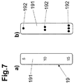
- the Figs. 7a , b show examples of possible embodiments of the charge level indicator 19.
- the charge level indicator can be designed to be at least visually perceptible, for example in the form of number (s) or symbol (s) printed on, engraved or embossed into the material.
- the charge status display can also be designed to be haptically perceptible.
- the charge level indicator 19 can be designed with heavily indented and thus easily perceptible numbers and / or symbols.
- the charge level indicator is designed on the magazine body 11, in which the numbers and / or symbols, similar to the principle of Braille, are designed as raised points or elevations 192.
- These elevations 192 can also be formed in a recessed area 191.
- the elevations 192 are preferably designed in such a way that they do not protrude from the outer contour of the magazine 10 in order to enable the magazine to be changed easily.
- the charge level indicator 19 can also be designed to be luminescent, that is to say easily recognizable even in the dark. Charge level displays with a single optical or haptic embodiment are possible, or also as a combination of several optical and / or haptic embodiments.
- the specified coordinate system does not have to be orthogonal and, especially in the case of curved magazines, can rotate relative to the magazine bottom even with the position under consideration and / or the angle of the z-axis with respect to that spanned by xy Can change level, as this coordinate system is only used to explain the situation at hand.
- the magazine 10 according to the invention can be made largely of plastic or metal, for example. Furthermore, different material combinations of plastic, metal, ceramic or composite material are possible.
- the magazine according to the invention can be produced, for example, by means of machining processes such as milling, turning or grinding, and the magazine according to the invention can also be produced using shaping processes such as injection molding, extrusion or MIM, or by means of additive processes Manufacturing processes such as 3D printing or a combination of these or other processes are carried out.
Landscapes
- Engineering & Computer Science (AREA)
- General Engineering & Computer Science (AREA)
- Portable Nailing Machines And Staplers (AREA)
Abstract
Description
- Die Erfindung betrifft einen verbessertes Magazin für Feuerwaffen, welches eine zerlegbare Ladehilfe umfasst, die leicht, werkzeuglos und verlustsicher eingebaut werden kann und leicht und unter Zuhilfenahme eines lediglich einfachen Werkzeuges vom Magazin entfernt werden kann, entsprechend dem Oberbegriff des Anspruches 1.
- Das erfindungsgemäße Magazin ist eine Abwandlung an sich bekannter Magazine für z.B. Pistolen und andere Feuerwaffen. Die Verbesserungen sind durch die erzielbaren Effekte bzw. Vorteile, wie nachstehend angeführt, erreichbar.
- Es wird in der gesamten Beschreibung und den Ansprüchen "vor" bzw. "(nach) vorne" als Richtung zur Mündung des Laufes hin, "(nach) hinten" als Richtung zum Schaft hin, "(nach) unten" als Richtung von den Magazinlippen zum Magazinboden hin, und "(nach) oben" als Richtung vom Magazinboden in Richtung Magazinlippen weg benutzt.
- Als "seitliche Flächen" sind in Mündungsrichtung betrachtet sowohl nach links als auch rechts liegende Flächen zwischen dem vorderen und hinteren Ende bezeichnet.
Die Bezeichnungen "Magazin", "Zubringer", "Magazinboden", "Magazinplatte", etc. haben die übliche Bedeutung, die der Fachmann ihnen im Stand der Technik beimisst. Flächen "parallel" zu einer Achse bilden zylindrische Mantelflächen aus, "Ausnehmungen" beziehen sich auf umliegende Bereiche des betrachteten Gegenstandes, etc. - Bei halb- und automatischen Feuerwaffen kann die Patronenzufuhr beispielsweise mittels Magazin erfolgen. Gebräuchliche Magazinformen für halb und vollautomatische Feuerwaffen sind z.B. das Kastenmagazin, Stangenmagazin und Kurvenmagazin.
- Ein Magazin umfasst üblicherweise einen länglichen Körper mit weitgehend rechteckigem Querschnitt. Am oberen Ende befinden sich Magazinlippen und eine Öffnung, um die jeweils oberste Patrone in den Laderaum einer Feuerwaffe transportieren zu können. Am unteren Ende befindet sich ein Magazinboden, der mit dem Magazinkörper verbunden ist. Im Magazinkörper, zwischen oberem und unterem Ende befindet sich, von oben betrachtet, ein Zubringer der mit einer Magazinfeder verbunden ist, wobei die Magazinfeder direkt oder mittels Bodenplatte mit dem Magazinboden verbunden ist.
- Die Federkraft der Feder drückt den Zubringer nach oben, bei leerem Magazin bis zu den Magazinlippen. Zum Befüllen werden Patronen von oben durch die Öffnung derartig in das Magazin geschoben, dass der Zubringer jeweils ein Stück entgegen der Federkraft nach unten geschoben wird. Die Feder wir mit jeder zusätzlichen ins Magazin geschobenen Patrone stärker vorgespannt, folglich ist für das Einschieben der jeweils nächsten Patrone in das Magazin immer stärkerer Druck nach untern erforderlich. Das Befüllen des Magazins wird außerdem durch mögliches Abrutschen der runden Patronenhülse voneinander erschwert, auch wirken die zur Patronenspitze hin konische Ausführungen und bei Randfeuerpatronen der größere Durchmesser des Patronenbodens im Vergleich zur Hülse erschwerend. Das herkömmliche Befüllen eines Magazins mit Patronen gestaltet sich entsprechend schwierig, insbesondere je stärker ein Magazin bereits befüllt ist. Das Befüllen benötigt entsprechend Zeit, Geschicklichkeit und Kraft.
- Der Stand der Technik kennt entsprechend seit langer Zeit Ladehilfen, die ein Befüllen von Magazinen mit Patronen erleichtern.
- Die
US 9,846,004 B2 US 2018/231 339 A1 beispielsweise offenbaren jeweils ein Magazin mit Schlitz in einer der Seitenwände und einem Zubringer mit einer Öffnung, an der ein Werkzeug an einer Seite des Magazins angesetzt werden kann, um den Zubringer nach unten zu drücken. Das einseitige Ansetzen des Werkzeugs wirkt nachteilig, da ein Verkanten und Steckenbleiben des Zubringers beim nach unten Schieben möglich ist. Weiters wirkt nachteilig, dass die Ladehilfe nur in Kombination: "Magazin mit Werkzeug" entsteht, also ein separates Werkzeug erforderlich ist. - Die
US 2019/219 352 A1 zeigt ein Magazin mit seitlichem Schlitz und einem auf einer Seite des Zubringers angebrachten und über den Magazinkörper herausstehenden Knopf, an dem der Zubringer nach unten geschoben werden kann. Durch die einseitige Anbringung des Knopfes ist ein Verkanten und Steckenbleiben des Zubringers möglich. Ebenfalls nachteilig wirkt der nicht bündige Abschluss des Knopfes mit dem Magazinkörper nachteilig. Eine derartiger über den Magazinkörper stehende und fest mit dem Zubringer verbundene Ladehilfe wird auch in derUS 2016/003 568 A1 gezeigt. Eine über den Magazinkörper hinaus stehende Ladehilfe kann nicht ohne weiteres in den Magazinschacht einer Feuerwaffe eingeführt werden, es sind besondere Bauformen notwendig, die beispielsweise mehr Platz und Material benötigen und/oder in schwereren Magazinen resultieren. - Die
GB 110577 A - Der Inhalt dieser Druckschriften wird für die Jurisdiktionen, in denen dies möglich ist, durch Bezugnahme zum Inhalt der Offenbarung dieser Anmeldung gemacht.
- Die Aufgabe der vorliegenden Erfindung liegt darin, die genannten Nachteile im Stand der Technik zu vermeiden und ein Magazin mit verlustsicherer, leicht zerlegbarer Ladehilfe bereitzustellen. Eine weitere Aufgabe für Ausgestaltungen der Erfindung liegt darin, ein optimiertes, betriebssicheres Magazin bereitzustellen, und den Ladestand des Magazins leicht und auch bei fehlendem Sichtkontakt erkenntlich zu machen.
- Erfindungsgemäß werden diese Ziele dadurch erreicht, dass ein Magazin der eingangs genannten Art die im kennzeichnenden Teil des Anspruchs 1 angegebenen Merkmale aufweist. Mit anderen Worten, das Magazin umfasst auf jeder Seitenwand einen Schlitz, einen Zubringer mit Schieberaufnahme und eine Ladehilfe, wobei die Ladehilfe einen ersten und zweiten Schieber umfasst, die innerhalb der Schieberaufnahme mittels zumindest einer Rast koppelbar ausgebildet ist. Zur Entkoppelung der zumindest einen Rast ist am Zubringer als Zerlegeöffnung zumindest ein Loch vorgesehen.
- Die erfindungsgemäße Lösung schafft ein Magazin mit einer vor Verlust gesicherten, aber dennoch leicht zerlegbaren Ladehilfe. Die Ladehilfe ist über den gesamten vertikal verschiebbaren Bereich hinter die Kontur des Magazinkörpers zurücktretend bis maximal bündig ausgebildet. Somit kann das Magazin auch mit eingebauter Ladehilfe störungsfrei und unter Vermeidung von Ladehemmungen in einer Feuerwaffe verwendet werden. Des Weiteren kann die Ladehilfe, lediglich unter Zuhilfenahme eines einfachen Werkzeuges wie z.B. eines Zerlegestifts, mittels leichtem Druck auf zumindest einen rastbildenden Vorsprung durch die Zerlegeöffnung / das Loch in eine Zerlegeposition gebracht und in weiterer Folge zerlegt werden.
- Als besonders vorteilhaft hat sich erwiesen, dass die Ladehilfe zwei ineinander einführbare Schieber aufweist. Die Schieber sind im ineinander einführbaren Bereich formkomplementär zueinander, mit Bolzenaufnahme und Schieberbolzen, ausgebildet. Die Ladehilfe kann hierdurch leicht in das zusammengebaute Magazin eingebaut werden, es ist lediglich das Einsetzen des ersten und zweiten Schiebers in die Schieberaufnahme und das Zusammendrücken der Schieber mit z.B. den Fingern notwendig.
- Besonders zweckmäßig ist ein von der Bolzenaufnahme ausgehender, im Einbauzustand mit dem Loch verbundener Durchbruch, an dem eine Anschlagfläche und Abstützfläche ausgebildet ist. Die Anschlagfläche ist dem zweiten Griff vorzugsweise näher als die Abstützfläche. Am ersten Schieber ist ein Fortsatz mit in Radialrichtung hervortretendem Vorsprung, der eine Rast und Endfläche bildet, ausgebildet, wobei die Rast dem ersten Griff näher ist als die Endfläche. Der Vorsprung ist formkomplementär zum Durchbruch ausgebildet und weist bevorzugt nach unten.
- Der Vorteil dieser Ausführungsform ist, dass die Rast des ersten Schiebers mit der Abstützfläche des zweiten Schiebers zusammenwirkt und eine Relativbewegung, in Axialrichtung des zweiten Schieberbolzens, des ersten Schiebers weg vom zweiten Schieber verhindert. Weiters wirkt die Endfläche des ersten Schiebers mit der Anschlagfläche des zweiten Schiebers zusammen und verhindert die Relativbewegung, in Axialrichtung des zweiten Schieberbolzens, des ersten Schiebers und des zweiten Schiebers zueinander. Im Einbauzustand sind die beiden Schieber der Ladehilfe fest miteinander verbunden.
- Mit anderen Worten ist der Fortsatz elastisch relativ zum ersten Schieberbolzen in Richtung einer Zerlegeposition auslenkbar. In der Zerlegeposition ist der Fortsatz mit dem die Rast bildendem Vorsprung frei von der Abstützfläche, wodurch ein axiales Auseinanderschieben der beiden Schieber ermöglicht wird.
- Ferner kann vorgesehen werden, dass der Zubringer eine als Loch ausgeführte Zerlegeöffnung aufweist, welches den Durchbruch und damit den Vorsprung zugänglich macht. Eine Krafteinwirkung, im Wesentlichen normal auf die Achse des zweiten Schieberbolzens, auf den Vorsprung stellt die Rast von der Abstützfläche frei und definiert somit eine Zerlegeposition.
- Ein derartiges Loch bietet den Vorteil, dass mittels eines einfachen Werkzeuges wie z.B. einem Zerlegestift leicht Druck auf den Vorsprung ausgeübt werden kann, um die Rast freizustellen, wodurch das Zerlegen der Ladehilfe auch am zusammengebauten Magazin problemlos möglich ist. Das Zerlegen der Ladehilfe erfolgt nach Druckausübung auf den Vorsprung lediglich durch leichtes Auseinanderziehen an den beiden Griffen.
- Vorteilhaft ist eine Ausprägung, gemäß welcher am ersten und/oder zweiten Griff erste und/oder zweite Seitenflächen zu einer Nutseite der Nut und eine erste und/oder zweite Innenfläche zu einem Nutboden der Nut formkomplementär ausgebildet sind.
- Auf diese Weise kann bei vertikaler Bewegung des Zubringers im Schlitz die erste und zweite Seitenflächen mit der Nutseite beziehungsweise erste und zweite Innenflächen mit dem Nutboden zusammenzuwirken und von diesen geführt werden. Diese Führung stabilisiert die Ausrichtung des Zubringers in x, y und z Achse (x-Achse: vorne/hinten; y-Achse: links/rechts und z-Achse: Vertikal bzw. in Richtung der Magazinachse und damit im Wesentlichen parallel zum Schlitz) und wirkt somit gegen das Verkanten.
- Besonders zweckmäßig kann ausgeführt sein, dass die Schieberaufnahme formkomplementär zum ersten Schieberbolzen ausgebildet ist. Die formkomplementäre Ausführung begünstigt einen festen Sitz der Ladehilfe in der Schieberaufnahme. Vorteilhaft ist ein im Querschnitt als Kreis ausgebildeter Schieberbolzen, da eine derartige Ausführung fertigungstechnisch vorteilhaft ist und mögliche auftretende Kräfte im Material besonders gut abgeleitet werden.
- Eine weiteren vorteilhaften Ausbildungsform ist eine im Querschnitt des zweiten Schieberbolzens und der Schieberaufnahme, einem Langloch gleiche, gestreckte Form mit zwei parallelen Längsflächen. Diese parallelen Längsflächen wirken mit der Schlitzseite zusammen, der Zubringer wird dadurch bei Vertikalbewegung zusätzlich geführt und der Anti-Verkant-Effekt verstärkt.
- In einer weiteren vorteilhaften Ausbildungsform weist der Querschnitt des zweiten Schieberbolzens und der Schieberaufnahme eine Stirnfläche auf. Durch diese Stirnfläche kann ein Einbau der Ladehilfe in falscher Orientierung, also mit dem Vorsprung vom Loch wegweisender Orientierung, verhindert werden.
- Eine weitere vorteilhafte Ausführung weist irgendwo am Querschnitt des zweiten Schieberbolzens und der Schieberaufnahme ein Asymmetrie-Element auf welches durch seine Form nur noch genau eine Orientierung für den Einbau der Ladehilfe im Magazin zulässt. Ein Einbau in falscher Orientierung, also z.B. mit von der Ladestandanzeige wegweisendem Indikator kann verhindert werden.
- Darüber hinaus kann ausgeführt sein, dass am ersten Schieber ein erster Indikator und/oder am zweiten Schieber ein zweiter Indikator und am Magazinkörper, bevorzugt an der Seite, eine Ladestandanzeige angeordnet ist. Indikator und/oder Ladestandanzeige können optisch, insbesondere lumineszierend und/oder haptisch wahrnehmbar, z.B. mittels Einkerbung, Vertiefung und/oder Erhebung ausgeführt sein.
- Vorteilhaft an einer derartigen Ausführung ist, dass der Nutzer den Ladestand des Magazins optisch sofort und leicht wahrnehmen kann. Bei lumineszierender Ausführung ist eine optische Wahrnehmung auch bei Dunkelheit möglich. Die haptische Ausführung erlaubt durch Ertasten ein Erkennen des Ladestands auch ohne Sichtkontakt.
- Weiters kann es zweckmäßig sein, dass die Grifffläche des ersten und/oder zweiten Griffs abrutschsicher ausgeführt ist und zumindest eine Anti-Abrutschkerbe aufweisen.
- Vorteilhaft ist daran, dass der Zubringer entgegen der Federkraft leicht nach unten zum Befüllen des Magazins geschoben werden kann, und auch bei friktionsarmen, rutschigen Bedingungen z.B. heißem feuchtem Wetter und Schweißbildung oder aber möglichen Verunreinigungen der Hände und/oder der Ladehilfe mit schmierenden oder ölhaltigen Substanzen ein sicheres und störungsfreies nach unten Schieben des Zubringers ohne Abzurutschen möglich ist und damit ein leichtes Befüllen des Magazins.
- Die Erfindung wird im Folgenden anhand der Zeichnung näher erläutert. Dabei zeigt bzw. zeigen:
- die
Figs. 1a,b ein erfindungsgemäßes Magazin in perspektivischer Explosionsansicht und in Seitenansicht, - die
Fig. 2 eine perspektivische Detailansicht des Zubringers mit der Ladehilfe vor dem Zusammenbau, - die
Fig. 3 einen axialen Schnitt durch die Ladehilfe im zerlegten Zustand, - die
Fig. 4 einen axialen Schnitt der Ladehilfe im Zubringer im eingebauten Zustand von hinten, - die
Fig. 5 die Ladehilfe im Zubringer im eingebauten Zustand von unten, - die
Fig. 6 verschiedene Ausführungsformen der Schieberaufnahme, rein schematisch, im Querschnitt und - die
Fig. 7 ) verschiedene Ausführungsformen der Ladestandanzeige, rein schematisch. - Es ist für den Fachmann klar, dass symmetrische Ausführungsformen problemlos möglich sind und sowohl in der Figurenbeschreibung als auch in den Ansprüchen im Stillen mitzulesen sind. Insbesondere sind Ausführungen des erfindungsgemäßen Magazins mit zumindest zwei an der Ladehilfe ausgebildeten Rasten möglich. Der Zubringer weist eine entsprechende Anzahl an Löchern auf, um die Rasten zugänglich zu machen und den Zerlegevorgang zu ermöglichen. Aus Gründen der einfacheren Darstellung und Kürze der Beschreibung wird in der nachfolgenden Beschreibung vornehmlich eine Ausführungsform mit lediglich einer Rast beschrieben.
- In den
Figuren 1 bis 7 sind vorrangig Ausführungsbeispiele der Erfindung dargestellt, die für eine Anwendung als Stangenmagazin in einer Pistole geeignet sind. Abwandlungen von den dargestellten und beschriebenen Beispielen können in Kenntnis der Erfindung auf andere Typen Magazinen und/oder von Feuerwaffen wie z.B. Gewehren vom Fachmann einfach und ohne umfangreiche oder komplexe Versuche übertragen werden. Auch beliebige, andere Kombinationen der technischen Merkmale der einzelnen dargestellten Figuren und deren unterschiedlicher Ausprägungsformen sind dem Fachmann in Kenntnis der Erfindung leicht möglich. - Die
Fig. 1a zeigt eine beispielhafte Ausführung eines erfindungsgemäßen Magazins 10 als Explosionszeichnung. Das Magazin 10 umfasst einen in Vertikalrichtung länglichen Magazinkörper 11 mit in Vertikalrichtung im Wesentlichen rechteckigen Querschnitt und damit eine schmälere vordere Fläche 111 (Fig. 1b ), eine schmälere hintere Fläche 113, zwei breitere Seiten 112 und eine oberes und ein unteres Ende. Weiters umfasst das Magazin 10 einen am unteren Ende des Magazinkörpers 11 befestigten Magazinboden 14, eine mit dem Magazinboden 14 zusammenwirkende Magazinplatte 15, am oberen Ende gelegene Lippen 13, eine Feder 16 sowie einen ebenfalls am oberen Ende gelegenen Zubringer 20. Die Feder 16 ist im zusammengebauten Zustand des Magazins an einem Ende mit dem Zubringer 20 und am anderen Ende mittels der Magazinplatte 15 mit dem Magazinboden 14 verbunden. Der Zubringer 20 wird durch die Federkraft nach oben in Richtung Lippen 15 gedrückt. Im befüllten Zustand wird so nach Entnahme der jeweils obersten Patrone die nächste nach oben befördert. Das Befüllen des Magazins 10 erfolgt durch Einführen von Patronen in das Magazin von oben durch Ausüben von Druck auf den Zubringer 20 entgegen der Kraft der Feder 16. - Der Magazinkörper 11 weist an seinen Seiten 112 jeweils einen länglichen und im Wesentlichen in Vertikalrichtung orientierten Schlitz 120 auf, der im Abstand sowohl vom Boden 14 als auch von den Lippen 13 endet, sodass der Magazinkörper 11 an seinen Seiten 113 oben und unten jeweils durchgängig ist
- In der dargestellten, bevorzugten Ausführung weist der Magazinkörper 11 an seinen Seiten 112 entlang des Schlitzes 120 eine Nut 170 mit Nutboden 171 und Nutseite 172 auf, wobei der Nutboden 171 im Wesentlichen parallel, die Nutseite 172 im Wesentlichen normal zur Seite 112 ausgebildet ist.
- Die zerlegbare Ladehilfe besteht aus einem ersten Schieber 30 und einen zweiten Schieber 40 und ist im eingebauten Zustand in einer Schieberaufnahme 21 des Zubringers 20 angeordnet. Im Einbauzustand durchdringt die zusammengebaute Ladehilfe den Magazinkörper 11 am Schlitz 120 und liegt vertieft oder bündig zu den Seiten 112.
- Die Ladehilfe wird beim Ladevorgang des Magazins 10 entgegen der Kraft der Feder 16 im Schlitz 120 nach geführt, wobei das Befüllen des Magazins 10 mit Patronen durch den mit der Ladehilfe nach unten gedrückten Zubringer 20 erleichtert wird.
- Die
Fig. 1b stellt das Magazin derFig. 1a in seitlicher Ansicht dar. Gut ersichtlich ist die Ladestandanzeige 19 sowie die Breite B1 des Schlitzes 120 und die Breite B2 der Nut 170. - Die
Fig. 2 zeigt den Zubringer 20 mit der Ladehilfe in axialer Explosionsdarstellung, Am Zubringer 20 befindet sich oben die Auflagefläche 23, welche bei gefülltem Magazin 10 mit der untersten Patrone in Kontakt steht. Ersichtlich ist weiters die am Hals 22 angeordnete Federaufnahme 25, an der die Feder mit dem Zubringer 20 verbunden ist. In der Schieberaufnahme 21 ist die aus dem ersten und dem zweiten Schieber 30 und 40 bestehende Ladehilfe angeordnet. Der erste Schieber 30 weist einen ersten Schieberbolzen 31 mit Fortsatz 34 und Vorsprung 37 auf. Der zweite Schieber 40 weist einen zweiten Schieberbolzen 41 mit Durchbruch 45, einen zweiten Griff 420, und einen optionalen zweiten Indikator 43 auf. Der optionale zweite Indikator 43 ist beispielhaft in Form eines Pfeils dargestellt. - Die
Fig. 3 zeigt einen Schnitt entlang der Linie IV-IV derFig. 1b der Ladehilfe im zerlegten Zustand, ohne die umgebenden Bauteile, dieFig. 4 einen gleichen Schnitt im Einbauzustand mit den umgebenden Bauteilen. - Wie in den
Figs. 3 und4 besonders gut erkennbar, ist der erste Schieberbolzen 31 formkomplementär zur Bolzenausnehmung 44 und kann von dieser aufgenommen werden. Der Fortsatz 34 mit dem Vorsprung 37, die Rast 36 und die Endfläche 38 sind formkomplementär zur Bolzenausnehmung 44 mit dem Durchbruch 45 geformt. Die Bolzenausnehmung 44 weist bevorzugt, wie dargestellt, eine Verjüngung 47, eine Abstützfläche 46 und eine Anschlagfläche 48 auf. Zum Zusammenbau der Ladehilfe wird der Fortsatz 34 des ersten Schiebers 30 in die Bolzenausnehmung 44 des zweiten Schiebers in Axialrichtung des zweiten Schieberbolzens (inFig. 4 mit VI bezeichnet) eingeführt, wobei der Vorsprung 37 in Richtung Loch 24, im gezeigten Beispiel inFig. 4 nach unten, orientiert ist. Der Fortsatz 34 ist relativ zum ersten Schieberbolzen 31 elastisch deformierbar ausgebildet, was einen einfachen Zusammenbau, respektive Zerlegevorgang, ermöglicht. Durch Zusammendrücken der Schieber 30 und 40 in axialer Richtung VI werden diese relativ zueinander bewegt und der erste Schieber 30 in den zweiten Schieber 40 gedrückt. Je weiter erster und zweiter Schieber 30 und 40 ineinander bewegt werden, desto stärker wird Fortsatz 34 nach dem Prinzip einer Blattfeder nach oben ausgelenkt. Erreicht der Fortsatz 34 mit Vorsprung 37 vollständig den Durchbruch 45 federt Fortsatz 34 zurück in seine ursprüngliche Lage. Durch Einrasten des Vorsprungs 37, respektive seiner Rast 36 an der Abstützfläche 46 des Durchbruchs 45 erfolgt die Kopplung. Bevorzugt, wie dargestellt, stößt zugleich die Endfläche 38 an der Anschlagfläche 48 an, wodurch sowohl eine axiale als auch eine rotierende Bewegung des ersten Schiebers 30 relativ zum zweiten Schieber 40 verhindert wird. - Zum Zerlegen der Ladehilfe wird Druck von unten auf den Vorsprung 37 ausgeübt und dieser durch elastische Deformation aus dem Durchbruch 45 gedrückt. Dabei gibt die Abstützfläche 46 die Rast 36 frei und der erste Schieber 30 kann aus dem zweiten Schieber 40 in Axialrichtung herausbewegt werden. Neben geeigneter Materialwahl unterstützt die besondere Ausformung der Biegenut 35 (nach Art einer Verjüngung der Querschnittsfläche) diesen Vorgang, da dadurch ein federndes Auslenken des Fortsatzes 34 nach oben ermöglicht und/oder erleichtert wird. Die Zerlegeposition wird somit dadurch erreicht, dass durch das Einwirken einer im Wesentlichen normal auf die Achse des zweiten Schieberbolzen 41 stehende Kraft durch das Loch 24 auf den Vorsprung 37 die Rast 36 von der Abstützfläche 46 freigestellt wird.
- Wie in
Fig. 4 gezeigt, weist der Zubringer 20 ein Loch 24 auf, um den Zugang mittels eines einfachen Werkzeugs wie z.B. einem Zerlegestift, zum Vorsprung 37 und damit ein Zerlegen der Ladehilfe im eingebauten Zustand im Magazin 10 zu ermöglichen. Es sind auch Ausführungen mit zumindest zwei an der Ladehilfe ausgebildeten Rasten 36 möglich. Der Zubringer 20 weist dann eine entsprechende Anzahl an Löchern 24 auf, um die Rasten 36 zugänglich zu machen und den Zerlegevorgang zu ermöglichen. - Der erste und zweite Griff 330 und 430 liegen in einer bevorzugten Ausbildung vollständig in der Nut 170 des Schlitzes 120 und schließen bündig mit den Seiten 112 des Magazinkörpers 11 ab. Besonders gut ist in
Fig. 3 ein nach oben innen verjüngter und somit leicht dreieckiger Querschnitt des ersten und zweiten Griffs 320 und 420 ersichtlich, welcher entsprechend der am oberen Ende leicht verjüngten Form des Magazinkörpers ausgebildet ist. Somit sind der erste und zweite Griff 320 und 420 auch bei Position im oberen Endbereich des Magazins 10 mit dem Magazinkörper 11 bündig, und die Ladehilfe ist auch bei in den Magazinschacht eingeschobenem Magazin 10 über die volle Länge des Schlitzes 120 von dieser Seite her frei beweglich. - In einer bevorzugten Ausführung und wie in
Fig. 2 gezeigt sind die Griffe 320 und 420 in Vertikalrichtung gestreckt ausgeführt und weisen jeweils zwei zumindest annähernd parallel zueinander und vertikal verlaufende erste und zweite Seitenflächen 322 und 422 auf. Der Normalabstand sowohl der beiden ersten Seitenflächen 322 als auch der beiden zweiten Seitenflächen 422 voneinander entspricht der Breite B2 der Nut 170 (gezeigt inFig. 1b ). Im Einbauzustand werden beide Griffe 320, 420 in der jeweils zugehörigen Nut 170 an der zugehörigen Seite 112 des Magazins 10 geführt, wobei die jeweils parallelen ersten und zweiten Seitenflächen 322 und 422 auch parallel zur jeweiligen Nut 170 ausgerichtet sind. Die entsprechend zum ersten und/oder zweiten Griff 320, 420 zugehörige Nutseite 172 führt die Seitenflächen 322, 422, wobei die Innenflächen 323, 423 auch parallel zur zugehörigen Nut 170 ausgerichtet sein können und vom zugehörigen Nutboden 171 geführt werden. - Durch das Zusammenwirken von Seitenflächen 322, 422 mit Nutseiten 172 bzw. von Innenflächen 323, 423 mit Nutböden 171 kann ein Verkanten in x, y und z Richtung des Zubringers bei Bewegung in Vertikalrichtung verhindert werden. Durch diesen Anti-Verkant-Effekt wird sowohl der Ladevorgang erleichtert, als auch eine optimierte Patronenzufuhr im Gebrauchsfall gefördert und mögliche Ladehemmungen hintangehalten.
- Die Breite / der Durchmesser des zweiten Schieberbolzens 41 entspricht im Wesentlichen der Breite B1 des Schlitzes 120 (
Fig. 1b ) und die Ladehilfe ist im Schlitz 120 in Vertikalrichtung beweglich geführt. In einer bevorzugten Ausführung kann der Schlitz 120 mittels dichtenden Elementen wie z.B. Dichtlippen oder Bürstendichtung geschlossen und gedichtet werden. Am Magazinkörper sind die Dichtelemente zum zeitweiligen Verschließen des Schlitzes 120 derart angeordnet, dass eine Vertikalbewegung der Ladehilfe möglich bleibt. Hierbei ist eine flexible Ausbildung der Dichtelemente vorteilhaft, wodurch der Schlitz 120 auch bei Bewegung des Zubringers 20 nach innen hin abgedichtet bleibt. Dadurch wird das ungewollte Eindringen von Fremdkörpern wie z.B. Staub, Sand, Schmutz und Feuchtigkeit erschwert, die Beweglichkeit des Zubringers 20 begünstigt und Ladehemmungen werden vermieden. - Wie in
Fig. 7a und b gezeigt, ist bevorzugt am ersten und/oder am zweiten Schieber 30, 40; z.B. an der ersten oder zweiten Grifffläche 321 und 421 des ersten oder zweiten Griffs 320 und 420 ein erster und/oder zweiter Indikator 33, 34 angebracht. Der erste und/oder zweite Indikator 33 und 43 wirkt mit einer zugeordneten Ladestandanzeige 19 zusammen und machen den tatsächlichen Füllstand des Magazins erkenntlich. Der Indikator kann optisch und/oder haptisch wahrnehmbar ausgeführt sein. Beispielsweise kann der Indikator als Pfeil oder Strichmarkierung, und/oder als Erhebung oder Einkerbung und/oder lumineszierend, also auch bei Dunkelheit leicht erkennbar, ausgeführt sein. Die Ladestandanzeige 19 kann z.B. durch Anbringung von Nummern und/oder Symbolen, optisch und/oder haptisch wahrnehmbar und/oder lumineszierend, den minimalen und maximalen Füllstand sowie Zwischenstufen ausgeführt sein. Je nach Füllgrad des Magazins liegt die Ladehilfe und damit der erste und/oder zweite Indikator 34 und 44 in unterschiedlicher vertikaler Position und zeigt auf die zugehörige Stelle der Ladestandanzeige 19 wodurch dem Benutzer der Füllgrad (Füllstand) des Magazins mit Patronen erkenntlich gemacht wird. - Die
Fig. 5 zeigt eine Ausführung eines Zubringers 20 des erfindungsgemäßen Magazins 10 mit eingesetzter Ladehilfe, wobei beide Schieber 30, 40 sichtbar sind, in einer Unteransicht. Insbesondere ist in der Mitte des Zubringers 20 das Loch 24 ersichtlich, mit dahinterliegendem Vorsprung 37 des ersten Schiebers 30. Das Loch 24 erlaubt zum Zerlegen der Ladehilfe durch Eingreifen mittels eines einfachen Werkzeugs wie z.B. einem Zerlegestift Druck nach oben auf den Vorsprung 37 und damit Fortsatz 34 auszuüben. Wie zuvor beschrieben wird auf diese Weise die Rast 36 von der Abstützfläche 46 freigestellt und die axiale Bewegung des ersten und zweiten Schiebers 30 und 40 voneinander weg ermöglicht. Die Position, in der die Rast 36 vom der Abstützfläche 46 freigestellt ist, wird als Zerlege-Position bezeichnet. - Die
Figs. 6a -c zeigen Beispiele für mögliche Ausführungen des Querschnitts der Schieberaufnahme 21 und damit der Schieberbolzen 31, 41, im schematischen Schnitt. Die Ladehilfe, insbesondere der erste Schieberbolzen 41, weist eine entsprechende formkomplementäre Ausgestaltung auf. Neben der inFig. 1 und2 gut ersichtlichen kreisrunden Ausformung kann die Schieberaufnahme beispielsweise auch eine einem Langloch ähnliche, gestreckte Form mit zwei parallelen Längsflächen 26 aufweisen (Fig. 6a ). Die Längsflächen 26 wirken mit der Schlitzfläche 121 zusammen und erhöhen den bereits beschriebenen Anti-Verkant-Effekt abermals. -
Fig. 6b zeigt eine Variante mit zusätzlicher Stirnfläche 27. Die Stirnfläche 27 verhindert ein verkehrtes Einsetzen der Ladehilfe mit vom Loch 24 weg orientiertem Durchbruch 45 und Vorsprung 37. In Zusammenschau mit den Beispielen derFig. 1 bis 5 würde die Ladehilfe nur mit Durchbruch 45 und Vorsprung 37 nach unten und somit dem Loch 24 zugewandt eingebaut werden können.Fig. 6c zeigt eine weitere mögliche Ausführungsform des Querschnitts der Schieberaufnahme 21, worin ein Asymmetrie-Element 28 einen völlig asymmetrischen Querschnitt bedingt. Hierdurch kann die Ladehilfe nur noch in genau einer einzigen Orientierung eingeführt werden, bei der der Durchbruch 45 dem Vorsprung 37 und dem Loch 24 zugewandt ist und der erste und/oder zweite Indikator 34, 44 der Ladehilfe 19 zugewandt ist. Ein derartiger asymmetrischer Querschnitt kann natürlich auch andere Ausgestaltungen aufweisen. - Die
Figs. 7a,b zeigen Beispiele möglicher Ausführungsformen der Ladestandanzeige 19. Die Ladestandanzeige kann zumindest optisch wahrnehmbar ausgeführt sein, z.B. in Form von aufgedruckten, gravierten oder ins Material geprägten Zahl(en) oder Symbol(en). Zusätzlich kann die Ladestandanzeige auch haptisch wahrnehmbar ausgeführt sein. Beispielsweise kann die Ladestandanzeige 19 mit stark eingekerbten und somit leicht fühlbaren Nummern und/oder Symbolen ausgeführt sein. In einer bevorzugten Ausführung ist die Ladestandanzeige am Magazinkörper 11 ausgeführt, in dem die Nummern und/oder Symbole, dem Prinzip der Blindenschrift ähnlich, als erhabene Stellen bzw. als Erhebungen 192, bezeichnet ausgeführt sind. Diese Erhebungen 192 können auch in einem vertieften Bereich 191 ausgebildet sein. Die Erhebungen 192 sind bevorzugt derart ausgebildet, dass sie gegenüber der Außenkontur des Magazins 10 nicht hervortreten um ein leichtgängiges Wechseln des Magazins zu ermöglichen. - Die Ladestandanzeige 19 kann auch lumineszierend, also auch bei Dunkelheit leicht erkennbar, ausgeführt sein. Es sind Ladestandanzeigen mit einer einzelnen optischen oder haptischen Ausführungsform möglich, oder auch als Kombination mehrerer optischer und/oder haptischer Ausführungsformen.
- Es soll noch speziell darauf hingewiesen werden, dass das angegebene Koordinatensystem nicht orthogonal sein muss und sich, speziell bei gebogenen Magazinen, auch mit der jeweils betrachteten Lage relativ zum Magazinboden Drehen kann und/oder sich der Winkel der z-Achse bezüglich der durch xy aufgespannten Ebene ändern kann, da dieses Koordinatensystem nur zur Erläuterung der jeweils vorliegenden Situation dient.
- Das erfindungsgemäße Magazin 10 kann beispielsweise weitgehend aus Kunststoff oder Metall hergestellt werden. Weiters sind unterschiedliche Materialkombinationen aus Kunststoff, Metall, Keramik oder auch Verbundwerkstoff möglich.
- Die Herstellung des erfindungsgemäßen Magazins kann beispielsweise mittels spanabhebender Verfahren wie z.B. Fräsen, Drehen oder Schleifen erfolgen, ebenso kann das erfindungsgemäße Magazin mit formgebenden Verfahren wie beispielsweise dem Spritzgießen, Extrudieren oder MIM, oder aber auch mittels additiver Fertigungsverfahren wie z.B. 3D-Druck oder eine Kombination dieser oder anderer Verfahren erfolgen.
-
10 Magazin 30 erster Schieber 11 Magazinkörper 31 erster Schieberbolzen 111 vordere Fläche 320 erste Griff 112 Seite 321 erste Grifffläche 113 hintere Fläche 322 erste Seitenfläche 120 Schlitz 323 erste Innenfläche 121 Schlitzfläche 33 erster Indikator 13 Lippen 34 Fortsatz 14 Magazinboden 35 Biegenut 15 Magazinplatte 36 Rast 16 Feder 37 Vorsprung 170 Nut 38 Endfläche 171 Nutboden 172 Nutseite 40 zweiter Schieber 19 Ladestandanzeige 41 zweiter Schieberbolzen 191 Vertiefter Bereich 420 zweiter Griff 192 Erhebung 421 zweite Grifffläche 422 zweite Seitenfläche 20 Zubringer 423 zweite Innenfläche 21 Schieberaufnahme 43 zweiter Indikator 22 Hals 44 Bolzenausnehmung 23 Auflagefläche (für unterste Patrone) 45 Durchbruch 24 Loch 46 Abstützfläche 25 Federaufnahme 47 Verjüngung 26 Längsfläche 48 Anschlagfläche 27 Stirnfläche 28 Asymmetrie-Element
Claims (17)
- Magazin für eine Feuerwaffe umfassend einen Magazinkörper (11) mit mindestens einem Schlitz (120) in jeder der beiden Seiten (112), einen Zubringer (20) mit einer Schieberaufnahme (21) und eine Ladehilfe, dadurch gekennzeichnet, dass die Ladehilfe einen ersten und zweiten Schieber (30, 40) aufweist, welche mittels einer Rast (36) innerhalb der Schieberaufnahme (21) koppelbar ausgebildet sind und der Zubringer (20) in Richtung der Schieberaufnahme (21) zumindest ein Loch (24) zur Entkoppelung der Rast (36) aufweist.
- Magazin nach Anspruch 1 dadurch gekennzeichnet, dass erster und zweiter Schieber (30, 40) ineinander einführbar ausgeführt sind.
- Magazin nach einem der Ansprüche 1 oder 2, dadurch gekennzeichnet, dass eine Bolzenausnehmung (44) des zweiten Schiebers (40) formkomplementär zu einem ersten Schieberbolzen (31) des ersten Schiebers (30) ausgeführt ist.
- Magazin nach einem der Ansprüche 1 bis 3, dadurch gekennzeichnet, dass am zweiten Schieber (40) ein mit der Bolzenausnehmung (44) verbundener und im Einbauzustand zum Loch (24) weisender Durchbruch (45) ausgebildet ist.
- Magazin nach einem der voranstehenden Ansprüche, dadurch gekennzeichnet, dass am Durchbruch (45) eine Abstützfläche (46) und eine Anschlagfläche (48) ausgebildet sind, wobei die Anschlagfläche (48) einem zweitem Griff (420) näher ist als die Abstützfläche (46).
- Magazin nach einem der voranstehenden Ansprüche, dadurch gekennzeichnet, dass am ersten Schieber (30) ein Fortsatz (34) und daran ein in Radialrichtung, bevorzugt nach unten, zur Bildung der Rast (36) und einer Endfläche (38) hervortretender Vorsprung (37) ausgebildet ist, wobei die Rast (36) einem ersten Griff (320) näher ist als die Endfläche (38).
- Magazin nach einem der Ansprüche 4 bis 6, dadurch gekennzeichnet, dass der Vorsprung (37) in seinen Abmessungen zum Durchbruch (45) komplementär ausgebildet ist.
- Magazin nach einem der voranstehenden Ansprüche, dadurch gekennzeichnet, dass der Fortsatz (34) elastisch relativ zum ersten Schieberbolzen (31) in Richtung einer Zerlege-Position auslenkbar ist.
- Magazin nach einem der voranstehenden Ansprüche, dadurch gekennzeichnet, dass am ersten und/oder zweiten Griff (320, 420) erste und/oder zweite Seitenflächen (322, 422) zu einer Nutseite (172) der Nut (170) und eine erste und/oder zweite Innenfläche (323, 423) zu einem Nutboden (171) der Nut (170) formkomplementär ausgebildet sind.
- Magazin nach einem der voranstehenden Ansprüche, dadurch gekennzeichnet, dass die Schieberaufnahme (21) im Querschnitt formkomplementär zum, bevorzugt kreisförmigen, Querschnitt des zweiten Schieberbolzens (41) ausgebildet ist.
- Magazin nach Anspruch 10, dadurch gekennzeichnet, dass der Querschnitt des zweiten Schieberbolzens (41) in Form eines Langlochs mit zwei parallelen Längsflächen (26) ausgeführt ist.
- Magazin nach einem der Ansprüche 10 oder 11, dadurch gekennzeichnet, dass der Querschnitt des zweiten Schieberbolzens (41) mindestens eine im Wesentlichen normal zu den Längsflächen (26) ausgerichtete Stirnfläche (27) aufweist.
- Magazin nach einem der Ansprüche 10 bis 12, dadurch gekennzeichnet, dass der Querschnitt des zweiten Schieberbolzens (41) mindestens ein Asymmetrie-Element (28) aufweist.
- Magazin nach einem der voranstehenden Ansprüche, dadurch gekennzeichnet, dass am ersten Schieber (30) ein erster Indikator (33) und/oder am zweiten Schieber (40) ein zweiter Indikator (43) und am Magazinkörper (11), bevorzugt an einer Seite (112), eine Ladestandanzeige (19) angeordnet ist.
- Magazin nach Anspruch 14, dadurch gekennzeichnet, dass der Indikator (33, 43) und/oder die Ladestandanzeige (19) optisch, bevorzugt lumineszierend, und/oder haptisch wahrnehmbar ausgeführt sind.
- Magazin nach einem der voranstehenden Ansprüche, dadurch gekennzeichnet, dass eine erste Grifffläche (321) eines ersten Griffs (320) und/oder eine zweite Grifffläche (421) eines zweiten Griffs (420) zumindest eine Anti-Abrutschkerbe aufweist.
- Magazin nach einem der voranstehenden Ansprüche, dadurch gekennzeichnet, dass am Magazinkörper (11) Dichtelemente, bevorzugt Dichtbürsten oder Dichtlippen, zum zeitweiligen Verschließen des Schlitz (120) derart angeordnet sind, dass eine Vertikalbewegung der Ladehilfe möglich bleibt.
Priority Applications (3)
| Application Number | Priority Date | Filing Date | Title |
|---|---|---|---|
| EP19210900.7A EP3825641B1 (de) | 2019-11-22 | 2019-11-22 | Magazin für feuerwaffen |
| PCT/EP2020/082014 WO2021099219A1 (en) | 2019-11-22 | 2020-11-13 | Magazine for firearms |
| US17/755,915 US11828561B2 (en) | 2019-11-22 | 2020-11-13 | Magazine for firearms |
Applications Claiming Priority (1)
| Application Number | Priority Date | Filing Date | Title |
|---|---|---|---|
| EP19210900.7A EP3825641B1 (de) | 2019-11-22 | 2019-11-22 | Magazin für feuerwaffen |
Publications (3)
| Publication Number | Publication Date |
|---|---|
| EP3825641A1 true EP3825641A1 (de) | 2021-05-26 |
| EP3825641B1 EP3825641B1 (de) | 2023-09-27 |
| EP3825641C0 EP3825641C0 (de) | 2023-09-27 |
Family
ID=68696219
Family Applications (1)
| Application Number | Title | Priority Date | Filing Date |
|---|---|---|---|
| EP19210900.7A Active EP3825641B1 (de) | 2019-11-22 | 2019-11-22 | Magazin für feuerwaffen |
Country Status (3)
| Country | Link |
|---|---|
| US (1) | US11828561B2 (de) |
| EP (1) | EP3825641B1 (de) |
| WO (1) | WO2021099219A1 (de) |
Citations (7)
| Publication number | Priority date | Publication date | Assignee | Title |
|---|---|---|---|---|
| GB110577A (en) | 1916-10-23 | 1917-10-23 | William Charles Walter Cowles | An Improved Cartridge Magazine for Automatic Pistols. |
| US20110107639A1 (en) * | 2009-11-10 | 2011-05-12 | James Lee Douglas | Easy Loading Magazine |
| US20140373416A1 (en) * | 2012-11-30 | 2014-12-25 | Craig M. Barnhart | High Capacity Magazine Efficient Loader Device and Related Method |
| US20160003568A1 (en) | 2013-04-30 | 2016-01-07 | Xtech, Llc | Quick Loading Firearm Magazine Systems and Methods |
| US9846004B2 (en) | 2015-12-21 | 2017-12-19 | Mike Micllef | Easy loading magazine |
| US20180231339A1 (en) | 2017-02-15 | 2018-08-16 | Joshua Walton | Firearm reloading system and method |
| US20190219352A1 (en) | 2017-04-10 | 2019-07-18 | David Maga | Loadable fixed magazine for sporting rifle |
Family Cites Families (9)
| Publication number | Priority date | Publication date | Assignee | Title |
|---|---|---|---|---|
| US1245499A (en) * | 1917-03-16 | 1917-11-06 | Gardner P Orme | Firearm-magazine. |
| US2137491A (en) * | 1936-10-24 | 1938-11-22 | William L Huff | Cartridge magazine latch for pistols |
| US2885811A (en) * | 1958-04-25 | 1959-05-12 | Jr Sherman C Womble | Follower latch for cartridge magazines |
| US5375359A (en) * | 1993-05-27 | 1994-12-27 | Ram-Line, Inc. | Magazine for housing 0.22 rimfire cartridges including truncated cartridges |
| US9103614B2 (en) * | 2010-11-29 | 2015-08-11 | David Froehle | Quick loading magazine |
| US10895427B2 (en) * | 2017-04-10 | 2021-01-19 | David Maga | Loadable fixed magazine for firearms |
| US10288371B2 (en) * | 2017-04-10 | 2019-05-14 | David Dallas Maga | Side-loading fixed magazine with retractable follower and sliding ammunition loading panel |
| DE102017120147B4 (de) * | 2017-09-01 | 2019-05-16 | Samsel-Magazin GbR (vertretungsberechtige Gesellschafterin: Irma Samsel, 27383 Scheeßel) | Magazin für eine Schusswaffe |
| US20200064091A1 (en) * | 2018-08-27 | 2020-02-27 | Vudoo Labs, Inc. dba Vudoo Gun Works, LLC | Ammunition magazine |
-
2019
- 2019-11-22 EP EP19210900.7A patent/EP3825641B1/de active Active
-
2020
- 2020-11-13 WO PCT/EP2020/082014 patent/WO2021099219A1/en not_active Ceased
- 2020-11-13 US US17/755,915 patent/US11828561B2/en active Active
Patent Citations (7)
| Publication number | Priority date | Publication date | Assignee | Title |
|---|---|---|---|---|
| GB110577A (en) | 1916-10-23 | 1917-10-23 | William Charles Walter Cowles | An Improved Cartridge Magazine for Automatic Pistols. |
| US20110107639A1 (en) * | 2009-11-10 | 2011-05-12 | James Lee Douglas | Easy Loading Magazine |
| US20140373416A1 (en) * | 2012-11-30 | 2014-12-25 | Craig M. Barnhart | High Capacity Magazine Efficient Loader Device and Related Method |
| US20160003568A1 (en) | 2013-04-30 | 2016-01-07 | Xtech, Llc | Quick Loading Firearm Magazine Systems and Methods |
| US9846004B2 (en) | 2015-12-21 | 2017-12-19 | Mike Micllef | Easy loading magazine |
| US20180231339A1 (en) | 2017-02-15 | 2018-08-16 | Joshua Walton | Firearm reloading system and method |
| US20190219352A1 (en) | 2017-04-10 | 2019-07-18 | David Maga | Loadable fixed magazine for sporting rifle |
Also Published As
| Publication number | Publication date |
|---|---|
| US20220381528A1 (en) | 2022-12-01 |
| US11828561B2 (en) | 2023-11-28 |
| WO2021099219A1 (en) | 2021-05-27 |
| EP3825641B1 (de) | 2023-09-27 |
| EP3825641C0 (de) | 2023-09-27 |
Similar Documents
| Publication | Publication Date | Title |
|---|---|---|
| DE3028958C2 (de) | ||
| DE69804149T2 (de) | Verriegelungshebelmechanismus für Verbinder | |
| DE202010008393U1 (de) | Verbindungsvorrichtung | |
| DE202014103965U1 (de) | Drehmomentschlüssel mit beidseitigem Antrieb | |
| DE102016012586B4 (de) | Lösbare Stielbefestigungskupplung für Arbeitsgeräte | |
| DE2617691A1 (de) | Bedienungsorgan | |
| DE102007061640C5 (de) | Kugelgelenkverbinder | |
| DE102012213772B4 (de) | Federklemme für gabelförmige Schlitten in flexiblen Scharnieren sowie ein entsprechendes flexibles Scharnier | |
| DE102005034063B3 (de) | Vorrichtung zum Verschließen von Gebäudeöffnungen | |
| DE102013109934B3 (de) | Bedienelement und Baugruppe für einen Luftausströmer sowie Verfahren zur Montage eines Bedienelements | |
| DE2918716C2 (de) | Bodenkehrer | |
| DE102007038254B4 (de) | Kupplungsglied für eine Mitnehmerkupplung und Herstellungsverfahren | |
| CH654508A5 (de) | Abstreifer sowie werkzeug zur montage dieses abstreifers. | |
| EP2156060B1 (de) | Befestiger zum lösbaren verbinden eines profils an ein gegenprofil | |
| DE202013105249U1 (de) | Elektromotorischer Linearantrieb | |
| DE20207486U1 (de) | Schraubendreher-Ratschenstruktur | |
| DE102020127229A1 (de) | Rotationsschneidwerkzeug sowie Schneidwerkzeugteile | |
| DE102012210226A1 (de) | Verstellvorrichtung für ein Fahrwerk eines Fahrzeugs | |
| EP3825641B1 (de) | Magazin für feuerwaffen | |
| EP0843064A2 (de) | Beschlag für ein Fenster | |
| DE10154692B4 (de) | Steckbolzen mit druckknopfbetätigter Axialsicherung | |
| DE102011089100A1 (de) | Verbindungseinheit und eine derartige Verbindungseinheit umfassende Verbindungsanordnung zur Herstellung einer unlösbaren Verbindung medienführender Leitungen | |
| DE202011050037U1 (de) | Werkzeugverbindungsstange | |
| DE2534375C2 (de) | Stiftförmige Vorrichtung zum federnden Verspannen zweier Bauteile | |
| DE2741292C2 (de) | Tastenschalter |
Legal Events
| Date | Code | Title | Description |
|---|---|---|---|
| PUAI | Public reference made under article 153(3) epc to a published international application that has entered the european phase |
Free format text: ORIGINAL CODE: 0009012 |
|
| STAA | Information on the status of an ep patent application or granted ep patent |
Free format text: STATUS: THE APPLICATION HAS BEEN PUBLISHED |
|
| AK | Designated contracting states |
Kind code of ref document: A1 Designated state(s): AL AT BE BG CH CY CZ DE DK EE ES FI FR GB GR HR HU IE IS IT LI LT LU LV MC MK MT NL NO PL PT RO RS SE SI SK SM TR |
|
| STAA | Information on the status of an ep patent application or granted ep patent |
Free format text: STATUS: REQUEST FOR EXAMINATION WAS MADE |
|
| 17P | Request for examination filed |
Effective date: 20211126 |
|
| RBV | Designated contracting states (corrected) |
Designated state(s): AL AT BE BG CH CY CZ DE DK EE ES FI FR GB GR HR HU IE IS IT LI LT LU LV MC MK MT NL NO PL PT RO RS SE SI SK SM TR |
|
| GRAP | Despatch of communication of intention to grant a patent |
Free format text: ORIGINAL CODE: EPIDOSNIGR1 |
|
| STAA | Information on the status of an ep patent application or granted ep patent |
Free format text: STATUS: GRANT OF PATENT IS INTENDED |
|
| INTG | Intention to grant announced |
Effective date: 20230719 |
|
| GRAS | Grant fee paid |
Free format text: ORIGINAL CODE: EPIDOSNIGR3 |
|
| GRAA | (expected) grant |
Free format text: ORIGINAL CODE: 0009210 |
|
| STAA | Information on the status of an ep patent application or granted ep patent |
Free format text: STATUS: THE PATENT HAS BEEN GRANTED |
|
| AK | Designated contracting states |
Kind code of ref document: B1 Designated state(s): AL AT BE BG CH CY CZ DE DK EE ES FI FR GB GR HR HU IE IS IT LI LT LU LV MC MK MT NL NO PL PT RO RS SE SI SK SM TR |
|
| REG | Reference to a national code |
Ref country code: GB Ref legal event code: FG4D Free format text: NOT ENGLISH |
|
| REG | Reference to a national code |
Ref country code: CH Ref legal event code: EP |
|
| REG | Reference to a national code |
Ref country code: DE Ref legal event code: R096 Ref document number: 502019009478 Country of ref document: DE |
|
| REG | Reference to a national code |
Ref country code: IE Ref legal event code: FG4D Free format text: LANGUAGE OF EP DOCUMENT: GERMAN |
|
| U01 | Request for unitary effect filed |
Effective date: 20231025 |
|
| U07 | Unitary effect registered |
Designated state(s): AT BE BG DE DK EE FI FR IT LT LU LV MT NL PT SE SI Effective date: 20231102 |
|
| U20 | Renewal fee for the european patent with unitary effect paid |
Year of fee payment: 5 Effective date: 20231110 |
|
| PG25 | Lapsed in a contracting state [announced via postgrant information from national office to epo] |
Ref country code: GR Free format text: LAPSE BECAUSE OF FAILURE TO SUBMIT A TRANSLATION OF THE DESCRIPTION OR TO PAY THE FEE WITHIN THE PRESCRIBED TIME-LIMIT Effective date: 20231228 |
|
| PG25 | Lapsed in a contracting state [announced via postgrant information from national office to epo] |
Ref country code: RS Free format text: LAPSE BECAUSE OF FAILURE TO SUBMIT A TRANSLATION OF THE DESCRIPTION OR TO PAY THE FEE WITHIN THE PRESCRIBED TIME-LIMIT Effective date: 20230927 Ref country code: NO Free format text: LAPSE BECAUSE OF FAILURE TO SUBMIT A TRANSLATION OF THE DESCRIPTION OR TO PAY THE FEE WITHIN THE PRESCRIBED TIME-LIMIT Effective date: 20231227 Ref country code: HR Free format text: LAPSE BECAUSE OF FAILURE TO SUBMIT A TRANSLATION OF THE DESCRIPTION OR TO PAY THE FEE WITHIN THE PRESCRIBED TIME-LIMIT Effective date: 20230927 Ref country code: GR Free format text: LAPSE BECAUSE OF FAILURE TO SUBMIT A TRANSLATION OF THE DESCRIPTION OR TO PAY THE FEE WITHIN THE PRESCRIBED TIME-LIMIT Effective date: 20231228 |
|
| PG25 | Lapsed in a contracting state [announced via postgrant information from national office to epo] |
Ref country code: IS Free format text: LAPSE BECAUSE OF FAILURE TO SUBMIT A TRANSLATION OF THE DESCRIPTION OR TO PAY THE FEE WITHIN THE PRESCRIBED TIME-LIMIT Effective date: 20240127 |
|
| PG25 | Lapsed in a contracting state [announced via postgrant information from national office to epo] |
Ref country code: ES Free format text: LAPSE BECAUSE OF FAILURE TO SUBMIT A TRANSLATION OF THE DESCRIPTION OR TO PAY THE FEE WITHIN THE PRESCRIBED TIME-LIMIT Effective date: 20230927 |
|
| PG25 | Lapsed in a contracting state [announced via postgrant information from national office to epo] |
Ref country code: SM Free format text: LAPSE BECAUSE OF FAILURE TO SUBMIT A TRANSLATION OF THE DESCRIPTION OR TO PAY THE FEE WITHIN THE PRESCRIBED TIME-LIMIT Effective date: 20230927 Ref country code: RO Free format text: LAPSE BECAUSE OF FAILURE TO SUBMIT A TRANSLATION OF THE DESCRIPTION OR TO PAY THE FEE WITHIN THE PRESCRIBED TIME-LIMIT Effective date: 20230927 Ref country code: IS Free format text: LAPSE BECAUSE OF FAILURE TO SUBMIT A TRANSLATION OF THE DESCRIPTION OR TO PAY THE FEE WITHIN THE PRESCRIBED TIME-LIMIT Effective date: 20240127 Ref country code: ES Free format text: LAPSE BECAUSE OF FAILURE TO SUBMIT A TRANSLATION OF THE DESCRIPTION OR TO PAY THE FEE WITHIN THE PRESCRIBED TIME-LIMIT Effective date: 20230927 Ref country code: CZ Free format text: LAPSE BECAUSE OF FAILURE TO SUBMIT A TRANSLATION OF THE DESCRIPTION OR TO PAY THE FEE WITHIN THE PRESCRIBED TIME-LIMIT Effective date: 20230927 Ref country code: SK Free format text: LAPSE BECAUSE OF FAILURE TO SUBMIT A TRANSLATION OF THE DESCRIPTION OR TO PAY THE FEE WITHIN THE PRESCRIBED TIME-LIMIT Effective date: 20230927 |
|
| PG25 | Lapsed in a contracting state [announced via postgrant information from national office to epo] |
Ref country code: PL Free format text: LAPSE BECAUSE OF FAILURE TO SUBMIT A TRANSLATION OF THE DESCRIPTION OR TO PAY THE FEE WITHIN THE PRESCRIBED TIME-LIMIT Effective date: 20230927 |
|
| REG | Reference to a national code |
Ref country code: DE Ref legal event code: R097 Ref document number: 502019009478 Country of ref document: DE Ref country code: CH Ref legal event code: PL |
|
| PG25 | Lapsed in a contracting state [announced via postgrant information from national office to epo] |
Ref country code: MC Free format text: LAPSE BECAUSE OF FAILURE TO SUBMIT A TRANSLATION OF THE DESCRIPTION OR TO PAY THE FEE WITHIN THE PRESCRIBED TIME-LIMIT Effective date: 20230927 |
|
| PG25 | Lapsed in a contracting state [announced via postgrant information from national office to epo] |
Ref country code: CH Free format text: LAPSE BECAUSE OF NON-PAYMENT OF DUE FEES Effective date: 20231130 |
|
| PG25 | Lapsed in a contracting state [announced via postgrant information from national office to epo] |
Ref country code: MC Free format text: LAPSE BECAUSE OF FAILURE TO SUBMIT A TRANSLATION OF THE DESCRIPTION OR TO PAY THE FEE WITHIN THE PRESCRIBED TIME-LIMIT Effective date: 20230927 Ref country code: CH Free format text: LAPSE BECAUSE OF NON-PAYMENT OF DUE FEES Effective date: 20231130 |
|
| PLBE | No opposition filed within time limit |
Free format text: ORIGINAL CODE: 0009261 |
|
| STAA | Information on the status of an ep patent application or granted ep patent |
Free format text: STATUS: NO OPPOSITION FILED WITHIN TIME LIMIT |
|
| GBPC | Gb: european patent ceased through non-payment of renewal fee |
Effective date: 20231227 |
|
| 26N | No opposition filed |
Effective date: 20240628 |
|
| REG | Reference to a national code |
Ref country code: IE Ref legal event code: MM4A |
|
| PG25 | Lapsed in a contracting state [announced via postgrant information from national office to epo] |
Ref country code: IE Free format text: LAPSE BECAUSE OF NON-PAYMENT OF DUE FEES Effective date: 20231122 |
|
| PG25 | Lapsed in a contracting state [announced via postgrant information from national office to epo] |
Ref country code: GB Free format text: LAPSE BECAUSE OF NON-PAYMENT OF DUE FEES Effective date: 20231227 |
|
| PG25 | Lapsed in a contracting state [announced via postgrant information from national office to epo] |
Ref country code: IE Free format text: LAPSE BECAUSE OF NON-PAYMENT OF DUE FEES Effective date: 20231122 Ref country code: GB Free format text: LAPSE BECAUSE OF NON-PAYMENT OF DUE FEES Effective date: 20231227 |
|
| U20 | Renewal fee for the european patent with unitary effect paid |
Year of fee payment: 6 Effective date: 20241111 |
|
| PG25 | Lapsed in a contracting state [announced via postgrant information from national office to epo] |
Ref country code: CY Free format text: LAPSE BECAUSE OF FAILURE TO SUBMIT A TRANSLATION OF THE DESCRIPTION OR TO PAY THE FEE WITHIN THE PRESCRIBED TIME-LIMIT; INVALID AB INITIO Effective date: 20191122 |
|
| PG25 | Lapsed in a contracting state [announced via postgrant information from national office to epo] |
Ref country code: HU Free format text: LAPSE BECAUSE OF FAILURE TO SUBMIT A TRANSLATION OF THE DESCRIPTION OR TO PAY THE FEE WITHIN THE PRESCRIBED TIME-LIMIT; INVALID AB INITIO Effective date: 20191122 |
|
| PG25 | Lapsed in a contracting state [announced via postgrant information from national office to epo] |
Ref country code: TR Free format text: LAPSE BECAUSE OF FAILURE TO SUBMIT A TRANSLATION OF THE DESCRIPTION OR TO PAY THE FEE WITHIN THE PRESCRIBED TIME-LIMIT Effective date: 20230927 |
|
| U20 | Renewal fee for the european patent with unitary effect paid |
Year of fee payment: 7 Effective date: 20251111 |
|
| U1N | Appointed representative for the unitary patent procedure changed after the registration of the unitary effect |
Representative=s name: BABELUK PATENTANWAELTE GMBH; AT |