EP3824543B1 - Procédé pour obtenir des paramètres de fonctionnement d'un moteur électrique et moteur électrique correspondant - Google Patents
Procédé pour obtenir des paramètres de fonctionnement d'un moteur électrique et moteur électrique correspondant Download PDFInfo
- Publication number
- EP3824543B1 EP3824543B1 EP19734685.1A EP19734685A EP3824543B1 EP 3824543 B1 EP3824543 B1 EP 3824543B1 EP 19734685 A EP19734685 A EP 19734685A EP 3824543 B1 EP3824543 B1 EP 3824543B1
- Authority
- EP
- European Patent Office
- Prior art keywords
- state
- parameter
- detected
- state change
- stored
- Prior art date
- Legal status (The legal status is an assumption and is not a legal conclusion. Google has not performed a legal analysis and makes no representation as to the accuracy of the status listed.)
- Active
Links
Images


Classifications
-
- H—ELECTRICITY
- H02—GENERATION; CONVERSION OR DISTRIBUTION OF ELECTRIC POWER
- H02P—CONTROL OR REGULATION OF ELECTRIC MOTORS, ELECTRIC GENERATORS OR DYNAMO-ELECTRIC CONVERTERS; CONTROLLING TRANSFORMERS, REACTORS OR CHOKE COILS
- H02P21/00—Arrangements or methods for the control of electric machines by vector control, e.g. by control of field orientation
- H02P21/0003—Control strategies in general, e.g. linear type, e.g. P, PI, PID, using robust control
- H02P21/0021—Control strategies in general, e.g. linear type, e.g. P, PI, PID, using robust control using different modes of control depending on a parameter, e.g. the speed
-
- H—ELECTRICITY
- H02—GENERATION; CONVERSION OR DISTRIBUTION OF ELECTRIC POWER
- H02P—CONTROL OR REGULATION OF ELECTRIC MOTORS, ELECTRIC GENERATORS OR DYNAMO-ELECTRIC CONVERTERS; CONTROLLING TRANSFORMERS, REACTORS OR CHOKE COILS
- H02P29/00—Arrangements for regulating or controlling electric motors, appropriate for both AC and DC motors
- H02P29/02—Providing protection against overload without automatic interruption of supply
- H02P29/024—Detecting a fault condition, e.g. short circuit, locked rotor, open circuit or loss of load
-
- G—PHYSICS
- G05—CONTROLLING; REGULATING
- G05B—CONTROL OR REGULATING SYSTEMS IN GENERAL; FUNCTIONAL ELEMENTS OF SUCH SYSTEMS; MONITORING OR TESTING ARRANGEMENTS FOR SUCH SYSTEMS OR ELEMENTS
- G05B23/00—Testing or monitoring of control systems or parts thereof
- G05B23/02—Electric testing or monitoring
- G05B23/0205—Electric testing or monitoring by means of a monitoring system capable of detecting and responding to faults
- G05B23/0259—Electric testing or monitoring by means of a monitoring system capable of detecting and responding to faults characterized by the response to fault detection
- G05B23/0264—Control of logging system, e.g. decision on which data to store; time-stamping measurements
-
- G—PHYSICS
- G05—CONTROLLING; REGULATING
- G05B—CONTROL OR REGULATING SYSTEMS IN GENERAL; FUNCTIONAL ELEMENTS OF SUCH SYSTEMS; MONITORING OR TESTING ARRANGEMENTS FOR SUCH SYSTEMS OR ELEMENTS
- G05B23/00—Testing or monitoring of control systems or parts thereof
- G05B23/02—Electric testing or monitoring
- G05B23/0205—Electric testing or monitoring by means of a monitoring system capable of detecting and responding to faults
- G05B23/0259—Electric testing or monitoring by means of a monitoring system capable of detecting and responding to faults characterized by the response to fault detection
- G05B23/0275—Fault isolation and identification, e.g. classify fault; estimate cause or root of failure
-
- G—PHYSICS
- G05—CONTROLLING; REGULATING
- G05B—CONTROL OR REGULATING SYSTEMS IN GENERAL; FUNCTIONAL ELEMENTS OF SUCH SYSTEMS; MONITORING OR TESTING ARRANGEMENTS FOR SUCH SYSTEMS OR ELEMENTS
- G05B23/00—Testing or monitoring of control systems or parts thereof
- G05B23/02—Electric testing or monitoring
- G05B23/0205—Electric testing or monitoring by means of a monitoring system capable of detecting and responding to faults
- G05B23/0259—Electric testing or monitoring by means of a monitoring system capable of detecting and responding to faults characterized by the response to fault detection
- G05B23/0275—Fault isolation and identification, e.g. classify fault; estimate cause or root of failure
- G05B23/0281—Quantitative, e.g. mathematical distance; Clustering; Neural networks; Statistical analysis
-
- H—ELECTRICITY
- H02—GENERATION; CONVERSION OR DISTRIBUTION OF ELECTRIC POWER
- H02P—CONTROL OR REGULATION OF ELECTRIC MOTORS, ELECTRIC GENERATORS OR DYNAMO-ELECTRIC CONVERTERS; CONTROLLING TRANSFORMERS, REACTORS OR CHOKE COILS
- H02P29/00—Arrangements for regulating or controlling electric motors, appropriate for both AC and DC motors
- H02P29/02—Providing protection against overload without automatic interruption of supply
Definitions
- the invention relates to a method for acquiring operating parameter data of a motor system with an electric motor.
- the motor system can preferably be provided as a component for a fan.
- the invention relates to an engine system for recording operating parameter data.
- the invention relates to a fan with a corresponding motor system.
- the term "motor system" is to be understood in the broadest sense.
- the teachings of the invention can be applied, for example, to an electric motor, to an arrangement of several electric motors, to electric motor groups, or to several electric motor systems.
- the motor system can include a control device with a processor and memory.
- Determining the remaining service life of a component or assembly is especially important when failure would result in consequential damage, as is the case, for example, in thermally critical applications. For example, if the cooling system or a part of it fails in a server room, this can lead to overheating and operational downtime or even destruction of servers and other hardware. The cooling of other complex and/or expensive electronic systems is similarly critical. In such application scenarios, it is helpful if an impending failure is indicated early on so that the component at risk of failure can be replaced in a timely manner before the failure occurs. Furthermore, it is particularly relevant in this regard if, in the event of a malfunction or following a damage event, at least an evaluation and analysis of operating parameter data can be performed to enable root cause identification.
- converters such as those used to control electric motors, such as EC (electronically commutated) motors
- EC electrolytic capacitors in the intermediate circuit or in switching power supplies
- Capacitors are subject to severe temperature- and load-current-dependent aging, which is why their service life can vary considerably.
- electric motors are widely used in fans, from microdrives to servomotors to high-performance drives. Like many mechanically moving devices, electric motors are subject to (mechanical) wear. In electric motors with slip rings, the slip ring and sliding contacts are particularly affected. However, even electric motors without slip rings can become inoperable due to wear. Among the mechanical components, the motor shaft bearings are particularly affected.
- the extent of wear depends particularly on the operating conditions of the electric motor. If the electric motor is operated at temperatures that are too high or too low, for example, the bearing grease can no longer lubricate optimally, and the bearing will therefore fail more quickly. Severe vibrations can also shorten the service life of the bearing, as the bearings must dissipate additional forces caused by the vibrations. This gives rise to the need to know the physical quantities that influence the operating parameters of an electric motor. With knowledge of the relevant physical quantities, then a wear-prone operation of the electric motor can be detected or, in the event of a failure that has already occurred, a replacement motor suitable for the expected operating parameters can be selected.
- the present invention is therefore based on the object of designing and developing a method for acquiring operating parameter data of a motor system comprising an electric motor of the type mentioned above in such a way that improved and/or more efficient acquisition and storage of operating parameter data, preferably directly in/on the motor system, is possible. Furthermore, a corresponding motor system and a corresponding fan are to be specified.
- This provides a method for detecting operating parameter data of a motor system with an electric motor, preferably for a fan, wherein states of operating parameters are detected during operation of the motor system, wherein the operating parameters comprise a basic parameter and at least one additional parameter, wherein, based on a state detection of the basic parameter, state change events of the basic parameter are determined, wherein upon detection of a state change event of the basic parameter, a state of the additional parameter is detected, and wherein the detected state of the additional parameter is stored in a link with the detected state change event.
- the fan further comprises a motor system according to claim 16.
- the operating parameter data of an engine system required for subsequent analyses and evaluations are reduced as much as possible during data acquisition.
- a selection method can be implemented which determines whether or not the current operating point should be evaluated or saved.
- states of operating parameters are therefore recorded during operation.
- the operating parameters comprise a basic parameter and at least one additional parameter.
- predefinable state change events of the basic parameter are determined based on a state detection of the basic parameter.
- a state of the additional parameter preferably prevailing at the time of detection of the state change event, is then recorded.
- the recorded state of the additional parameter is then stored in a link with the detected state change event.
- the method according to the invention for acquiring operating parameter data of an engine system, the engine system according to the invention, and the fan according to the invention enable improved and/or more efficient acquisition and storage of operating parameter data in the engine system.
- the invention is therefore based on the idea of acquiring relevant operating points of the engine system, particularly with regard to relevant components of the engine system, in a storage-efficient manner, so that operating data are available for any analyses based on them in the event of damage (cause determination), or so that the operating parameter data can be used as a long-term database. can be used for the systematic development and optimization of the engine system or its components.
- a control unit or control device with memory functionality is provided for the engine system or the electric motors used.
- a predeterminable state change event to be determined—particularly within the scope of the claims and preferably within the scope of the description—can be understood as a specific or defined state change event in which the state of an operating parameter changes significantly. It is conceivable that the predeterminable state change event is determined—rigidly or non-rigidly—with regard to its significance prior to engine operation. Furthermore, it is conceivable that a predeterminable state change event can be understood as a state change event that can be independently created and/or adapted by the engine system during a learning phase of the engine system during customer operation and/or during ongoing operation of the engine system. Thus, it is conceivable that, within the scope of an advantageous embodiment, the predeterminable state change event is not rigidly specified or predefined, but rather can be adapted during operation by a learning engine system.
- the state can be obtained based on measurements.
- the state of an operating parameter is calculated, for example, based on operation-specific simulations. A combined use of simulation data and real measurement data may also be possible.
- the term "detected state" of an operating parameter (basic parameter and/or additional parameter) can be understood to mean that the state is acquired by measurement and/or calculation.
- the "operating parameters of an electric motor of a motor system” can include various information that characterizes the operating conditions of the electric motor or motor system. Such operating parameters can include, for example, the operating temperature, the bearing temperature, vibration stress, the orientation of the electric motor, the speed, or the air humidity. This short and non-exhaustive list shows what all operating parameters of an electric motor can be. In principle, anything that directly or indirectly influences the service life of an electric motor or motor system can be such an operating parameter.
- the physical quantity recorded by a sensor that is representative of the respective operating parameter can be correspondingly diverse. An operating parameter or its status can thus be recorded based on one or more measured – preferably physical – quantities. Furthermore, it is conceivable that an operating parameter or its status can be recorded based on data obtained through internal processing or simulation and/or possibly through calculations.
- the electronics of the engine system can preferably have a memory configured to store recorded states of the operating parameters.
- the memory can preferably be designed as a non-volatile memory.
- a non-volatile memory can be, for example, a flash memory, an EEPROM (electronically erasable programmable read-only memory), an NVRAM (non-volatile random access memory), or another semiconductor memory.
- a predefined classification can be used for the status recording of an operating parameter, whereby a recorded status of the operating parameter is assigned to a predefined class of the classification.
- a class can, for example, correspond to a predefined operating parameter range. Accordingly, a division by range of an operating parameter within a defined operating parameter range can be referred to as a class.
- the measuring range of the operating parameters can be conveniently subdivided into classes of equal size, so that the classification of an operating parameter is defined equidistantly.
- the classification of an operating parameter is defined nonlinearly.
- the specifiable classification—and thus the classes specified by the classification— can be determined prior to engine operation, thus providing a predefined classification. Furthermore, it is conceivable that the classification—and thus the classes specified by the classification—can be created and/or adjusted for an operating parameter during engine system operation and/or during a learning phase of the engine system, possibly individually.
- a state of one or more additional parameters prevailing at the time of detection of the state change event can be detected, wherein the detected state of the additional parameter(s) is/are also stored in association with the detected state change event. Consequently, additional operating parameter data can be efficiently preserved or stored in relation to the respectively detected state change event.
- the detected state change event of the base parameter and the detected state of the additional parameter are stored as a state combination. Furthermore, if multiple additional parameters are taken into account, the detected states of the additional parameters and the detected state change event are stored as a state combination. This means that the detected state change event and the detected state of the additional parameter and, if applicable, the detected state of the further additional parameter(s) can be stored as a state combination.
- the state combination can therefore be stored depending on the change in the base parameter. Consequently, a storage-efficient method can be provided, whereby relevant operating states of the engine system are recorded in the form of the state combination as a result of detected state change events, and a measure for storing the state combination is initiated or executed depending on the detected characteristic state change in the base parameter.
- the detected state change event is stored by the state combination in such a way that the start state and target state of the state change of the detected state change event of the base parameter are stored in the state combination.
- the state before the characteristic state change and the state after the characteristic state change are stored as the start and target states of the state change event of the base parameter.
- state combinations generated due to detected state change events during operation can be stored in or by means of a matrix.
- the matrix comprises matrix elements that are addressable via the columns and rows of the matrix.
- the matrix can be implemented as a multidimensional matrix or as a nested matrix. be implemented, with each matrix element in turn storing further subelements.
- the subelements can include scalars, vectors, and/or matrices.
- the state combinations are stored in the matrix in such a way that a distribution of the detected state change events of the base parameter is available.
- the respective state changes of the state change events of the base parameter are available for subsequent operational data analysis.
- the state combinations in the matrix are stored in such a way that the start states and target states of the state change events are mapped via matrix indices, preferably column indices and row indices. Information regarding the number of state events can conveniently be stored in the matrix elements. This allows for simple and efficient storage of the recorded operating states.
- information about the detected states of additional parameters can be stored in the matrix elements of the matrix.
- the matrix can be a nested matrix with matrix elements, where the matrix elements can in turn comprise vectors and/or one or more matrices.
- various information about additional parameters, in particular the detected states of the additional parameters can be efficiently stored or saved in the nested matrix.
- the state of the base parameter determined by the state detection of the base parameter can be subjected to evaluation/analysis at predefined or predefined evaluation intervals in order to detect a state change event of the base parameter.
- a state change event can represent a predefined change in the state of the base parameter.
- the evaluation can be implemented in such a way that a state change event of the base parameter is detected when a predeterminable change threshold, in particular a state change threshold, is exceeded.
- a predeterminable change threshold in particular a state change threshold
- the operating parameters can include a speed parameter, a temperature parameter, a current parameter, and/or a voltage parameter, etc.
- operating parameters of the motor system or the electric motor that are of particular importance for any subsequent analysis and/or optimization of the motor system can be taken into account and stored.
- Operating parameters can thus include information about speed, temperature, current, voltage, etc.
- gradients or other mathematical derivatives derived from these are also conceivable.
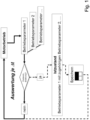
- Fig. 1 shows a schematic view of a block diagram of a method for detecting operating parameter data of an engine system according to an embodiment of the invention.
- Fig. 1 shows the principle of a method according to an exemplary embodiment, which can be applied, for example, to an external rotor motor of a motor system or a fan.
- predefined state change events of the operating parameter 1 are determined based on a state detection of the operating parameter 1 as the base parameter. This means that during motor operation, the state of the operating parameter 1 is recorded over time, whereby the state of the operating parameter 1 determined in the predeterminable evaluation intervals ⁇ t is subjected to an evaluation so that predefined or characteristic state changes of the operating parameter 1 are detected.
- a storage function is triggered.
- characteristic state changes are detected via associated operating parameters and, if necessary, a storage function is triggered.
- the storage function is then configured such that the change in state of operating parameter 1, together with the corresponding state of operating parameter 2 and, if applicable, the states of other operating parameters, is stored as a state combination.
- a corresponding memory can be provided in the motor system or in the fan. Motor operation continues continuously.
- relevant state combinations which represent relevant operating parameter states, can be detected and stored depending on a change in the state of a base parameter, in this case, operating parameter 1.
- the operating state of the engine system associated with the state change event is characterized by the extent of the quantitative change in the base parameter, i.e., the change in the state of the base parameter, and by the states of at least one additional parameter present during the state change event.
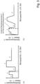
- Fig. 3a and Fig. 3b Each shows a diagram illustrating the states of an operating parameter determined over time.
- the x-axes in Fig. 3a or in Fig. 3b represent the reference value, for example, the time to which the states of operating parameter 1 or operating parameter 2 are related. Instead of time, values such as current, power, or temperature, or combinations of these values, could also be used as a reference value.
- the y-axis in Fig. 3a or in Fig. 3b represents the possible states of operating parameter 1 or operating parameter 2, whereby the value range of operating parameters 1 and 2 is divided into classes 1 to 10.
- the operating parameter 1 serves as the basic parameter, whereby the Fig. 3a
- the curve of the basic parameter shown represents an example of a speed parameter.
- Fig. 3a The evaluation interval ⁇ t illustrated by dashed lines shows a state change event in which a speed jump from class 4 to class 2 takes place.
- the operating parameter 2 serves as an additional parameter, whereby the Fig. 3b
- the curve of the additional parameter shown represents an example of a temperature parameter.
- the detection time of the state change event of the basic parameter is shown in the diagram according to Fig. 3b illustrated with a dashed vertical line.
- the state of the additional parameter at the time of detection of the state change event is thus Fig. 3b assigned to class 5.
- the temperature parameter acting as an additional parameter is recorded with state class 5.
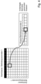
- Fig. 4 shows in a schematic view an exemplary storage of determined states of operating parameters as a state combination in a nested matrix according to an embodiment of the invention.
- Fig. 4 illustrates the storage of operating parameter data using the exemplary curves of operating parameter 1 and operating parameter 2 according to Fig. 3 , whereby the storage of data is carried out by storing the recorded operating states in the form of defined classes in a nested matrix.
- a class is defined as a division of operating parameters into a defined operating parameter value range.
- the classification of the operating parameters can be defined equidistantly or non-linearly.
- the detected state change event is stored in such a way that the start and target class, i.e. the state of operating parameter 1 as the basic parameter before and after the state change, can be traced.
- the number of entries in a matrix element describes the number the state change events characterized by the classification of operating parameter 1 as a basic parameter.
- information about other operating parameters namely the additional parameters, which are linked to the event of the state change of the base parameter, is also stored in an implemented program code.
- it can be stored as operating parameter data that a speed jump from class 4 to class 2 occurred for the base parameter (operating parameter 1) and that a temperature of class 5 was present at the additional parameter (operating parameter 2) at the time of the speed jump.
- Fig. 5 illustrates individual method steps of a method according to an embodiment of the invention in an overall overview.
- Operating parameter data of an engine system are recorded, wherein states of operating parameters 1 and 2 are recorded during operation of the engine system.
- Operating parameter 1 represents a basic parameter and operating parameter 2 represents an additional parameter.
- predefined state change events of operating parameter 1 are determined.
- a state of operating parameter 2 acting as the additional parameter - prevailing at the time of detection of the state change event - is recorded.
- the recorded state of operating parameter 2 is linked to the detected state change event and stored in a nested matrix.
- the detected state change event and the recorded state of the additional parameter are stored as a state combination in the matrix.
- the state combination is stored in the matrix such that the start state and the target state of the detected state change event are mapped across the columns and rows of the matrix.
- Information regarding the number of detected state events is stored in the matrix elements of the main matrix.
- information regarding recorded states of the additional parameter, namely operating parameter 2 is stored in the matrix elements.
- the characteristic state change of operating parameter 1 from start class 4 to target class 2 is stored in the main matrix.
- the corresponding matrix element also stores the state of the additional parameter at the time of detection of the state change event, namely class 5 for operating parameter 2, which functions as an additional parameter.
- a selection method is implemented that determines whether the current operating point should be evaluated or saved. Consequently, storage-efficient acquisition of operating parameter data is realized.
Landscapes
- Engineering & Computer Science (AREA)
- General Physics & Mathematics (AREA)
- Physics & Mathematics (AREA)
- Automation & Control Theory (AREA)
- Power Engineering (AREA)
- Mathematical Analysis (AREA)
- Evolutionary Computation (AREA)
- Mathematical Optimization (AREA)
- Mathematical Physics (AREA)
- Probability & Statistics with Applications (AREA)
- Pure & Applied Mathematics (AREA)
- Artificial Intelligence (AREA)
- Algebra (AREA)
- Control Of Electric Motors In General (AREA)
Claims (11)
- Procédé de mesure de données de paramètres de fonctionnement d'un système de moteur avec un moteur électrique, de préférence pour un ventilateur,dans lequel, pendant un fonctionnement du système de moteur, des états des paramètres de fonctionnement sont mesurés,dans lequel les paramètres de fonctionnement comprennent un paramètre de base et au moins un paramètre d'état,dans lequel, sur la base d'une mesure d'état du paramètre de base, des événements de changements d'états du paramètre de base sont déterminés,dans lequel, lors d'une détection d'un événement de changement d'état du paramètre de base, un état du paramètre additionnel est mesuré, dans lequel l'état mesuré du paramètre additionnel est enregistré de manière liée avec l'événement de changement d'état détecté, dans lequel l'événement de changement d'état et l'état mesure du paramètre additionnel et, le cas échéant l'état mesuré de l'autre paramètre additionnel ou les états mesurés des autres paramètres additionnels sont enregistrés en tant que combinaison d'états,le procédé est caractérisé en ce quedes combinaisons d'états, qui sont générés à la suite d'événements de changement d'état détectés, sont enregistrées au moyen d'une matrice, de préférence imbriquée, avec des éléments de matrice, dans lequel la combinaison d'états est enregistrée dans la matrice de sorte qu'une répartition des événements de changements d'états détectés du paramètre de base est disponible et dans lequel les combinaisons d'états sont enregistrés dans la matrice de sorte que, par l'intermédiaire d'index de la matrice, de préférence des index de colonnes des index cibles de la matrice, des états initiaux et des états cibles des événements de changement d'état sont représentés et dans lequel, dans les éléments de matrice de la matrice, sont enregistrées des informations concernant le nombre d'événements d'états.
- Procédé selon la revendication 1, caractérisé en ce que, lors de la mesure d'état d'un paramètre de fonctionnement, une classification est effectuée, dans lequel un état mesuré du paramètre de fonctionnement correspond à une classe de la classification.
- Procédé selon la revendication 1 ou 2, caractérisé en ce que, lors de la détection de l'événement de changement d'état du paramètre de base, un état d'un ou plusieurs autres paramètres additionnels est mesuré, dans lequel l'état mesuré de l'autre paramètre additionnel ou les états mesurés des autres paramètres additionnels sont enregistrés de manière liée avec l'événement de changement d'état détecté.
- Procédé selon l'une des revendications 1 à 3, caractérisé en ce que l'enregistrement de la combinaison d'états a lieu en fonction du changement du paramètre de base.
- Procédé selon l'une des revendications 1 à 4, caractérisé en ce que l'événement de changement d'état détecté est enregistré grâce à la combinaison d'états de sorte que l'état initial et l'état cible du changement d'état de l'événement de changement d'état détecté du paramètre de base sont enregistrés dans la combinaison d'états.
- Procédé selon l'une des revendications 1 à 5, caractérisé en ce que, dans les éléments de matrice de la matrice, sont enregistrées des informations concernant les états mesurés de paramètres additionnels.
- Procédé selon l'une des revendications 1 à 6, caractérisé en ce que l'état déterminé au moyen de la mesure d'état du paramètre de base est soumis, à des intervalles d'analyse prédéterminés, à une analyse afin de détecter un événement de changement d'état du paramètre de base,
dans lequel l'analyse peut être implémentée de sorte que, lors d'un dépassement d'un seuil de changement prédéterminé, un événement de changement d'état du paramètre de base est constaté. - Procédé selon l'une des revendications 1 à 7, caractérisé en ce que les paramètres de fonctionnement comprennent un paramètre de vitesse de rotation, un paramètre de température, un paramètre de courant et/ou un paramètre de tension, etc.
- Procédé selon l'une des revendications 1 à 8, caractérisé en ce que, en tant que paramètre de base, un paramètre de vitesse de rotation est utilisé et/ou en tant que paramètre de base un paramètre de tension est utilisé.
- Système de moteur pour la mesure de données de paramètres de fonctionnement et pour l'exécution d'un procédé selon l'une des revendications 1 à 9, le système de moteur comprenant :un moteur électrique avec un stator et un rotor rotatif par rapport au stator etun dispositif de commande avec un processeur et une mémoire, dans lequel le dispositif de commande est conçu de sorte que, pendant un fonctionnement du système de moteur, des états de paramètres de fonctionnement sont mesurés, dans lequel les paramètres de fonctionnement comprennent un paramètre de base et au moins un paramètre additionnel,dans lequel le dispositif de commande est en outre conçu de sorte que, sur la base d'une mesure d'état du paramètre de base, des événements de changements d'état du paramètre de base sont déterminés,lors d'une détection d'un événement de changement d'état du paramètre de base, un état du paramètre additionnel est mesuré etl'état mesuré du paramètre additionnel est enregistré dans la mémoire de manière liée avec l'événement de changement d'état détecté.
- Ventilateur avec un système de moteur selon la revendication 10, pour l'exécution d'un procédé selon l'une des revendications 1 à 9.
Priority Applications (1)
| Application Number | Priority Date | Filing Date | Title |
|---|---|---|---|
| SI201930933T SI3824543T1 (sl) | 2018-07-17 | 2019-05-29 | Postopek za pridobitev podatkov o obratovalnih parametrih motornega sistema z elektromotornim pogonom in ustreznega motornega sistema z elektromotornim pogonom |
Applications Claiming Priority (2)
| Application Number | Priority Date | Filing Date | Title |
|---|---|---|---|
| DE102018211882.5A DE102018211882A1 (de) | 2018-07-17 | 2018-07-17 | Verfahren zur Erfassung von Betriebsparameterdaten eines Motorsystems mit Elektromotor und entsprechendes Motorsystem |
| PCT/DE2019/200053 WO2020015795A1 (fr) | 2018-07-17 | 2019-05-29 | Procédé d'acquisition de données de paramètre de fonctionnement d'un système de moteur comprenant un moteur électrique et système de moteur correspondant |
Publications (2)
| Publication Number | Publication Date |
|---|---|
| EP3824543A1 EP3824543A1 (fr) | 2021-05-26 |
| EP3824543B1 true EP3824543B1 (fr) | 2025-04-30 |
Family
ID=67137502
Family Applications (1)
| Application Number | Title | Priority Date | Filing Date |
|---|---|---|---|
| EP19734685.1A Active EP3824543B1 (fr) | 2018-07-17 | 2019-05-29 | Procédé pour obtenir des paramètres de fonctionnement d'un moteur électrique et moteur électrique correspondant |
Country Status (9)
| Country | Link |
|---|---|
| US (1) | US11949359B2 (fr) |
| EP (1) | EP3824543B1 (fr) |
| JP (2) | JP2021530955A (fr) |
| KR (1) | KR20210044787A (fr) |
| CN (1) | CN112425067B (fr) |
| DE (1) | DE102018211882A1 (fr) |
| ES (1) | ES3031109T3 (fr) |
| SI (1) | SI3824543T1 (fr) |
| WO (1) | WO2020015795A1 (fr) |
Family Cites Families (23)
| Publication number | Priority date | Publication date | Assignee | Title |
|---|---|---|---|---|
| GB1370103A (en) * | 1971-10-15 | 1974-10-09 | Lucas Electrical Co Ltd | Process control apparatus |
| DE4113198A1 (de) * | 1991-04-23 | 1992-10-29 | Oplaender Wilo Werk Gmbh | Elektromotor, insbesondere spaltrohrmotor fuer eine kreiselpumpe oder einen luefter |
| JPH0932628A (ja) * | 1995-07-19 | 1997-02-04 | Nissan Motor Co Ltd | データ収集装置 |
| FR2751772B1 (fr) | 1996-07-26 | 1998-10-16 | Bev Bureau Etude Vision Soc | Procede et dispositif fonctionnant en temps reel, pour le reperage et la localisation d'une zone en mouvement relatif dans une scene, ainsi que pour la determination de la vitesse et la direction du deplacement |
| DE19742446B4 (de) * | 1997-09-26 | 2006-05-24 | Daimlerchrysler Ag | Fehlerdiagnoseverfahren |
| DE10048826B4 (de) | 2000-09-29 | 2012-03-01 | Robert Bosch Gmbh | Verfahren und Vorrichtung zur Erfassung alterungsbedingter Veränderungen von technischen Systemen wie Elektromotoren |
| DE10156218A1 (de) * | 2001-11-15 | 2003-06-05 | Metabowerke Gmbh | Handgeführtes oder halbstationäres Elektrowerkzeuggerät |
| JP2004201421A (ja) | 2002-12-19 | 2004-07-15 | Aisin Aw Co Ltd | 車両駆動制御装置、車両駆動制御方法及びそのプログラム |
| EP1604451A1 (fr) | 2003-03-03 | 2005-12-14 | Abb Ab | Dispositif et procede pour surveiller un appareil |
| JP4599969B2 (ja) | 2004-09-28 | 2010-12-15 | 富士電機システムズ株式会社 | 電力変換装置及び故障解析方法 |
| US7298110B2 (en) * | 2005-09-28 | 2007-11-20 | Caterpillar Inc. | Integrated motor monitoring system |
| US7705231B2 (en) * | 2007-09-07 | 2010-04-27 | Microsoft Corporation | Automatic accompaniment for vocal melodies |
| US8091667B2 (en) | 2006-06-07 | 2012-01-10 | GM Global Technology Operations LLC | Method for operating a hybrid electric powertrain based on predictive effects upon an electrical energy storage device |
| US7602132B2 (en) * | 2006-09-27 | 2009-10-13 | Rockwell Automation Technologies, Inc. | Methods and system for motor drive information capture |
| JP5167631B2 (ja) * | 2006-11-30 | 2013-03-21 | 株式会社デンソー | モータの制御方法及びそれを利用するモータ制御装置 |
| US7675257B2 (en) * | 2007-03-09 | 2010-03-09 | Regal Beloit Corporation | Methods and systems for recording operating information of an electronically commutated motor |
| CN101334667A (zh) | 2007-06-26 | 2008-12-31 | 株洲南车时代电气股份有限公司 | 机车状态信息检测与诊断记录的方法及装置 |
| US8314576B2 (en) * | 2009-07-17 | 2012-11-20 | Board Of Regents, The University Of Texas System | Methods and apparatuses for fault management in permanent magnet synchronous machines using the field reconstruction method |
| KR101932715B1 (ko) | 2011-11-14 | 2018-12-27 | 삼성전자주식회사 | 스테핑 모터 제어 장치 및 방법 |
| JP6082186B2 (ja) | 2012-03-23 | 2017-02-15 | セイコーエプソン株式会社 | 表示装置の制御装置、表示装置の制御方法、表示装置及び電子機器 |
| CN107592958B (zh) | 2015-05-18 | 2020-06-16 | 华为技术有限公司 | 不同码长下使用一个多比率指数表和一个扩展因子的多比率的ldpc编码和解码 |
| US9847701B2 (en) | 2015-12-01 | 2017-12-19 | GM Global Technology Operations LLC | Determination of rotor fatigue in an electric machine assembly |
| DE102016108506B3 (de) | 2016-05-09 | 2017-09-21 | Kriwan Industrie-Elektronik Gmbh | Verfahren zum Schutz einer nichtfahrenden, mit einem Elektromotor angetriebenen Arbeitsmaschine sowie nichtfahrende, mit einem Elektromotor angetriebene Arbeitsmaschine |
-
2018
- 2018-07-17 DE DE102018211882.5A patent/DE102018211882A1/de active Pending
-
2019
- 2019-05-29 JP JP2021501304A patent/JP2021530955A/ja active Pending
- 2019-05-29 EP EP19734685.1A patent/EP3824543B1/fr active Active
- 2019-05-29 WO PCT/DE2019/200053 patent/WO2020015795A1/fr not_active Ceased
- 2019-05-29 SI SI201930933T patent/SI3824543T1/sl unknown
- 2019-05-29 US US17/261,544 patent/US11949359B2/en active Active
- 2019-05-29 CN CN201980046243.XA patent/CN112425067B/zh active Active
- 2019-05-29 ES ES19734685T patent/ES3031109T3/es active Active
- 2019-05-29 KR KR1020217004480A patent/KR20210044787A/ko not_active Ceased
-
2024
- 2024-07-11 JP JP2024111744A patent/JP7730404B2/ja active Active
Also Published As
| Publication number | Publication date |
|---|---|
| WO2020015795A1 (fr) | 2020-01-23 |
| CN112425067B (zh) | 2024-10-11 |
| DE102018211882A1 (de) | 2020-01-23 |
| JP2021530955A (ja) | 2021-11-11 |
| CN112425067A (zh) | 2021-02-26 |
| JP2024133698A (ja) | 2024-10-02 |
| US11949359B2 (en) | 2024-04-02 |
| ES3031109T3 (en) | 2025-07-04 |
| JP7730404B2 (ja) | 2025-08-27 |
| US20210257955A1 (en) | 2021-08-19 |
| EP3824543A1 (fr) | 2021-05-26 |
| KR20210044787A (ko) | 2021-04-23 |
| SI3824543T1 (sl) | 2025-07-31 |
Similar Documents
| Publication | Publication Date | Title |
|---|---|---|
| EP3289419B1 (fr) | Procédé permettant de surveiller une unité de commande électronique et unité de commande destinée à un véhicule automobile | |
| DE10048826A1 (de) | Verfahren und Vorrichtung zur Erfassung alterungsbedingter Veränderungen von technischen Systemen wie Elektromotoren | |
| DE102016000368B4 (de) | Temperaturschätzvorrichtung eines Elektromotors | |
| WO2014044484A2 (fr) | Procédé de diagnostic pour véhicules ferroviaires | |
| DE102009030206A1 (de) | Verfahren zur Ermittlung der Abgastemperatur eines Fahrzeugmotors | |
| DE102016013406A1 (de) | Verfahren zum Betrieb eines Zustandsüberwachungssystems einer Schwingmaschine und Zustandsüberwachungssystem | |
| DE112019005836T5 (de) | System und verfahren zum sammeln von trainingsdaten | |
| DE102014100945A1 (de) | Vorrichtung sowie Verfahren zur Fehlererkennung in Maschinen | |
| EP3824543B1 (fr) | Procédé pour obtenir des paramètres de fonctionnement d'un moteur électrique et moteur électrique correspondant | |
| DE102022120965B4 (de) | Verfahren zum Vorhersagen der Rotortemperatur für einen Elektromotor | |
| WO2018178196A1 (fr) | Procédé de détermination d'une incertitude de mesure d'endommagement d'un véhicule automobile | |
| DE102013208209A1 (de) | Dichtung mit Sensoreinrichtung | |
| WO2020038815A1 (fr) | Détermination des états d'un dispositif au moyen de machines à vecteurs supports | |
| EP3786607A1 (fr) | Procédé de pronostic de dommages sur un composant d'un palier | |
| WO2011003917A1 (fr) | Surveillance de l'âge effectif de composants ou de blocs électroniques | |
| EP3765317B1 (fr) | Procédé servant à surveiller une installation de climatisation, dispositif de surveillance et installation de climatisation | |
| DE112019005429T5 (de) | Lagervorrichtung | |
| DE102022134209B3 (de) | Verfahren, Diagnoseeinrichtung und System zum Überwachen eines Betriebs einer Brennkraftmaschine | |
| DE102019201985B4 (de) | Verfahren zum Erkennen eines Fehlers einer elektrischen Maschine für ein Fahrzeug | |
| DE102014222637A1 (de) | Verfahren und Vorrichtung zur Überwachung einer rotierenden Maschine | |
| EP4002680B1 (fr) | Procédé et système de maintenance basée sur l'état d'un dispositif d'accès | |
| DE102020133000A1 (de) | Verfahren zur Bestimmung und Erkennung von Zuständen, Zustandsänderungen und Fehlern einer Strömungsmaschine | |
| EP1260894A2 (fr) | Procédé pour actionner un entraínement et dispositif | |
| DE102019120493A1 (de) | Verfahren zur Bereitstellung einer Messfunktion für eine Temperaturmessvorrichtung sowie Verwendung einer Messfunktion | |
| EP4390585B1 (fr) | Système de capteur |
Legal Events
| Date | Code | Title | Description |
|---|---|---|---|
| STAA | Information on the status of an ep patent application or granted ep patent |
Free format text: STATUS: UNKNOWN |
|
| STAA | Information on the status of an ep patent application or granted ep patent |
Free format text: STATUS: THE INTERNATIONAL PUBLICATION HAS BEEN MADE |
|
| PUAI | Public reference made under article 153(3) epc to a published international application that has entered the european phase |
Free format text: ORIGINAL CODE: 0009012 |
|
| STAA | Information on the status of an ep patent application or granted ep patent |
Free format text: STATUS: REQUEST FOR EXAMINATION WAS MADE |
|
| 17P | Request for examination filed |
Effective date: 20201123 |
|
| AK | Designated contracting states |
Kind code of ref document: A1 Designated state(s): AL AT BE BG CH CY CZ DE DK EE ES FI FR GB GR HR HU IE IS IT LI LT LU LV MC MK MT NL NO PL PT RO RS SE SI SK SM TR |
|
| DAV | Request for validation of the european patent (deleted) | ||
| DAX | Request for extension of the european patent (deleted) | ||
| STAA | Information on the status of an ep patent application or granted ep patent |
Free format text: STATUS: EXAMINATION IS IN PROGRESS |
|
| 17Q | First examination report despatched |
Effective date: 20230419 |
|
| GRAP | Despatch of communication of intention to grant a patent |
Free format text: ORIGINAL CODE: EPIDOSNIGR1 |
|
| STAA | Information on the status of an ep patent application or granted ep patent |
Free format text: STATUS: GRANT OF PATENT IS INTENDED |
|
| INTG | Intention to grant announced |
Effective date: 20241125 |
|
| P01 | Opt-out of the competence of the unified patent court (upc) registered |
Free format text: CASE NUMBER: APP_6188/2025 Effective date: 20250205 |
|
| GRAS | Grant fee paid |
Free format text: ORIGINAL CODE: EPIDOSNIGR3 |
|
| GRAA | (expected) grant |
Free format text: ORIGINAL CODE: 0009210 |
|
| STAA | Information on the status of an ep patent application or granted ep patent |
Free format text: STATUS: THE PATENT HAS BEEN GRANTED |
|
| AK | Designated contracting states |
Kind code of ref document: B1 Designated state(s): AL AT BE BG CH CY CZ DE DK EE ES FI FR GB GR HR HU IE IS IT LI LT LU LV MC MK MT NL NO PL PT RO RS SE SI SK SM TR |
|
| REG | Reference to a national code |
Ref country code: CH Ref legal event code: EP Ref country code: GB Ref legal event code: FG4D Free format text: NOT ENGLISH |
|
| REG | Reference to a national code |
Ref country code: IE Ref legal event code: FG4D Free format text: LANGUAGE OF EP DOCUMENT: GERMAN |
|
| REG | Reference to a national code |
Ref country code: DE Ref legal event code: R096 Ref document number: 502019013293 Country of ref document: DE |
|
| REG | Reference to a national code |
Ref country code: ES Ref legal event code: FG2A Ref document number: 3031109 Country of ref document: ES Kind code of ref document: T3 Effective date: 20250704 |
|
| PGFP | Annual fee paid to national office [announced via postgrant information from national office to epo] |
Ref country code: GB Payment date: 20250625 Year of fee payment: 7 |
|
| PGFP | Annual fee paid to national office [announced via postgrant information from national office to epo] |
Ref country code: FR Payment date: 20250627 Year of fee payment: 7 |
|
| PGFP | Annual fee paid to national office [announced via postgrant information from national office to epo] |
Ref country code: SI Payment date: 20250624 Year of fee payment: 7 |
|
| REG | Reference to a national code |
Ref country code: NL Ref legal event code: MP Effective date: 20250430 |
|
| PG25 | Lapsed in a contracting state [announced via postgrant information from national office to epo] |
Ref country code: FI Free format text: LAPSE BECAUSE OF FAILURE TO SUBMIT A TRANSLATION OF THE DESCRIPTION OR TO PAY THE FEE WITHIN THE PRESCRIBED TIME-LIMIT Effective date: 20250430 Ref country code: PT Free format text: LAPSE BECAUSE OF FAILURE TO SUBMIT A TRANSLATION OF THE DESCRIPTION OR TO PAY THE FEE WITHIN THE PRESCRIBED TIME-LIMIT Effective date: 20250901 |
|
| PGFP | Annual fee paid to national office [announced via postgrant information from national office to epo] |
Ref country code: ES Payment date: 20250704 Year of fee payment: 7 |
|
| PGFP | Annual fee paid to national office [announced via postgrant information from national office to epo] |
Ref country code: DE Payment date: 20250730 Year of fee payment: 7 |
|
| REG | Reference to a national code |
Ref country code: LT Ref legal event code: MG9D |
|
| PG25 | Lapsed in a contracting state [announced via postgrant information from national office to epo] |
Ref country code: NO Free format text: LAPSE BECAUSE OF FAILURE TO SUBMIT A TRANSLATION OF THE DESCRIPTION OR TO PAY THE FEE WITHIN THE PRESCRIBED TIME-LIMIT Effective date: 20250730 Ref country code: GR Free format text: LAPSE BECAUSE OF FAILURE TO SUBMIT A TRANSLATION OF THE DESCRIPTION OR TO PAY THE FEE WITHIN THE PRESCRIBED TIME-LIMIT Effective date: 20250731 |
|
| PG25 | Lapsed in a contracting state [announced via postgrant information from national office to epo] |
Ref country code: PL Free format text: LAPSE BECAUSE OF FAILURE TO SUBMIT A TRANSLATION OF THE DESCRIPTION OR TO PAY THE FEE WITHIN THE PRESCRIBED TIME-LIMIT Effective date: 20250430 Ref country code: NL Free format text: LAPSE BECAUSE OF FAILURE TO SUBMIT A TRANSLATION OF THE DESCRIPTION OR TO PAY THE FEE WITHIN THE PRESCRIBED TIME-LIMIT Effective date: 20250430 |
|
| PGFP | Annual fee paid to national office [announced via postgrant information from national office to epo] |
Ref country code: IT Payment date: 20250808 Year of fee payment: 7 |
|
| PG25 | Lapsed in a contracting state [announced via postgrant information from national office to epo] |
Ref country code: BG Free format text: LAPSE BECAUSE OF FAILURE TO SUBMIT A TRANSLATION OF THE DESCRIPTION OR TO PAY THE FEE WITHIN THE PRESCRIBED TIME-LIMIT Effective date: 20250430 |
|
| PG25 | Lapsed in a contracting state [announced via postgrant information from national office to epo] |
Ref country code: HR Free format text: LAPSE BECAUSE OF FAILURE TO SUBMIT A TRANSLATION OF THE DESCRIPTION OR TO PAY THE FEE WITHIN THE PRESCRIBED TIME-LIMIT Effective date: 20250430 |
|
| PG25 | Lapsed in a contracting state [announced via postgrant information from national office to epo] |
Ref country code: RS Free format text: LAPSE BECAUSE OF FAILURE TO SUBMIT A TRANSLATION OF THE DESCRIPTION OR TO PAY THE FEE WITHIN THE PRESCRIBED TIME-LIMIT Effective date: 20250731 |
|
| PG25 | Lapsed in a contracting state [announced via postgrant information from national office to epo] |
Ref country code: IS Free format text: LAPSE BECAUSE OF FAILURE TO SUBMIT A TRANSLATION OF THE DESCRIPTION OR TO PAY THE FEE WITHIN THE PRESCRIBED TIME-LIMIT Effective date: 20250830 |
|
| PG25 | Lapsed in a contracting state [announced via postgrant information from national office to epo] |
Ref country code: LV Free format text: LAPSE BECAUSE OF FAILURE TO SUBMIT A TRANSLATION OF THE DESCRIPTION OR TO PAY THE FEE WITHIN THE PRESCRIBED TIME-LIMIT Effective date: 20250430 |
|
| REG | Reference to a national code |
Ref country code: CH Ref legal event code: H13 Free format text: ST27 STATUS EVENT CODE: U-0-0-H10-H13 (AS PROVIDED BY THE NATIONAL OFFICE) Effective date: 20251223 |
|
| PG25 | Lapsed in a contracting state [announced via postgrant information from national office to epo] |
Ref country code: DK Free format text: LAPSE BECAUSE OF FAILURE TO SUBMIT A TRANSLATION OF THE DESCRIPTION OR TO PAY THE FEE WITHIN THE PRESCRIBED TIME-LIMIT Effective date: 20250430 Ref country code: SM Free format text: LAPSE BECAUSE OF FAILURE TO SUBMIT A TRANSLATION OF THE DESCRIPTION OR TO PAY THE FEE WITHIN THE PRESCRIBED TIME-LIMIT Effective date: 20250430 |
|
| PG25 | Lapsed in a contracting state [announced via postgrant information from national office to epo] |
Ref country code: LU Free format text: LAPSE BECAUSE OF NON-PAYMENT OF DUE FEES Effective date: 20250529 |
|
| PG25 | Lapsed in a contracting state [announced via postgrant information from national office to epo] |
Ref country code: CH Free format text: LAPSE BECAUSE OF NON-PAYMENT OF DUE FEES Effective date: 20250531 |
|
| PG25 | Lapsed in a contracting state [announced via postgrant information from national office to epo] |
Ref country code: CZ Free format text: LAPSE BECAUSE OF FAILURE TO SUBMIT A TRANSLATION OF THE DESCRIPTION OR TO PAY THE FEE WITHIN THE PRESCRIBED TIME-LIMIT Effective date: 20250430 |
|
| PG25 | Lapsed in a contracting state [announced via postgrant information from national office to epo] |
Ref country code: EE Free format text: LAPSE BECAUSE OF FAILURE TO SUBMIT A TRANSLATION OF THE DESCRIPTION OR TO PAY THE FEE WITHIN THE PRESCRIBED TIME-LIMIT Effective date: 20250430 |
|
| PG25 | Lapsed in a contracting state [announced via postgrant information from national office to epo] |
Ref country code: SK Free format text: LAPSE BECAUSE OF FAILURE TO SUBMIT A TRANSLATION OF THE DESCRIPTION OR TO PAY THE FEE WITHIN THE PRESCRIBED TIME-LIMIT Effective date: 20250430 Ref country code: RO Free format text: LAPSE BECAUSE OF FAILURE TO SUBMIT A TRANSLATION OF THE DESCRIPTION OR TO PAY THE FEE WITHIN THE PRESCRIBED TIME-LIMIT Effective date: 20250430 |
|
| REG | Reference to a national code |
Ref country code: BE Ref legal event code: MM Effective date: 20250531 |
|
| PG25 | Lapsed in a contracting state [announced via postgrant information from national office to epo] |
Ref country code: MC Free format text: LAPSE BECAUSE OF FAILURE TO SUBMIT A TRANSLATION OF THE DESCRIPTION OR TO PAY THE FEE WITHIN THE PRESCRIBED TIME-LIMIT Effective date: 20250430 |
|
| REG | Reference to a national code |
Ref country code: DE Ref legal event code: R097 Ref document number: 502019013293 Country of ref document: DE |
|
| PLBE | No opposition filed within time limit |
Free format text: ORIGINAL CODE: 0009261 |
|
| STAA | Information on the status of an ep patent application or granted ep patent |
Free format text: STATUS: NO OPPOSITION FILED WITHIN TIME LIMIT |
|
| REG | Reference to a national code |
Ref country code: CH Ref legal event code: L10 Free format text: ST27 STATUS EVENT CODE: U-0-0-L10-L00 (AS PROVIDED BY THE NATIONAL OFFICE) Effective date: 20260311 |
|
| 26N | No opposition filed |
Effective date: 20260202 |
|
| PG25 | Lapsed in a contracting state [announced via postgrant information from national office to epo] |
Ref country code: IE Free format text: LAPSE BECAUSE OF NON-PAYMENT OF DUE FEES Effective date: 20250529 |
|
| PG25 | Lapsed in a contracting state [announced via postgrant information from national office to epo] |
Ref country code: BE Free format text: LAPSE BECAUSE OF NON-PAYMENT OF DUE FEES Effective date: 20250531 |