EP3823523B1 - Neurovascular distal access support catheters, aspiration catheters, or device shafts - Google Patents
Neurovascular distal access support catheters, aspiration catheters, or device shafts Download PDFInfo
- Publication number
- EP3823523B1 EP3823523B1 EP19837373.0A EP19837373A EP3823523B1 EP 3823523 B1 EP3823523 B1 EP 3823523B1 EP 19837373 A EP19837373 A EP 19837373A EP 3823523 B1 EP3823523 B1 EP 3823523B1
- Authority
- EP
- European Patent Office
- Prior art keywords
- shaft
- catheter
- pattern
- segment
- flexible
- Prior art date
- Legal status (The legal status is an assumption and is not a legal conclusion. Google has not performed a legal analysis and makes no representation as to the accuracy of the status listed.)
- Active
Links
Images


Classifications
-
- A—HUMAN NECESSITIES
- A61—MEDICAL OR VETERINARY SCIENCE; HYGIENE
- A61M—DEVICES FOR INTRODUCING MEDIA INTO, OR ONTO, THE BODY; DEVICES FOR TRANSDUCING BODY MEDIA OR FOR TAKING MEDIA FROM THE BODY; DEVICES FOR PRODUCING OR ENDING SLEEP OR STUPOR
- A61M1/00—Suction or pumping devices for medical purposes; Devices for carrying-off, for treatment of, or for carrying-over, body-liquids; Drainage systems
- A61M1/84—Drainage tubes; Aspiration tips
-
- A—HUMAN NECESSITIES
- A61—MEDICAL OR VETERINARY SCIENCE; HYGIENE
- A61B—DIAGNOSIS; SURGERY; IDENTIFICATION
- A61B17/00—Surgical instruments, devices or methods
- A61B17/22—Implements for squeezing-off ulcers or the like on inner organs of the body; Implements for scraping-out cavities of body organs, e.g. bones; for invasive removal or destruction of calculus using mechanical vibrations; for removing obstructions in blood vessels, not otherwise provided for
- A61B17/221—Gripping devices in the form of loops or baskets for gripping calculi or similar types of obstructions
-
- A—HUMAN NECESSITIES
- A61—MEDICAL OR VETERINARY SCIENCE; HYGIENE
- A61M—DEVICES FOR INTRODUCING MEDIA INTO, OR ONTO, THE BODY; DEVICES FOR TRANSDUCING BODY MEDIA OR FOR TAKING MEDIA FROM THE BODY; DEVICES FOR PRODUCING OR ENDING SLEEP OR STUPOR
- A61M25/00—Catheters; Hollow probes
- A61M25/0043—Catheters; Hollow probes characterised by structural features
- A61M25/005—Catheters; Hollow probes characterised by structural features with embedded materials for reinforcement, e.g. wires, coils, braids
- A61M25/0051—Catheters; Hollow probes characterised by structural features with embedded materials for reinforcement, e.g. wires, coils, braids made from fenestrated or weakened tubing layer
-
- A—HUMAN NECESSITIES
- A61—MEDICAL OR VETERINARY SCIENCE; HYGIENE
- A61M—DEVICES FOR INTRODUCING MEDIA INTO, OR ONTO, THE BODY; DEVICES FOR TRANSDUCING BODY MEDIA OR FOR TAKING MEDIA FROM THE BODY; DEVICES FOR PRODUCING OR ENDING SLEEP OR STUPOR
- A61M25/00—Catheters; Hollow probes
- A61M25/0043—Catheters; Hollow probes characterised by structural features
- A61M25/0054—Catheters; Hollow probes characterised by structural features with regions for increasing flexibility
-
- A—HUMAN NECESSITIES
- A61—MEDICAL OR VETERINARY SCIENCE; HYGIENE
- A61M—DEVICES FOR INTRODUCING MEDIA INTO, OR ONTO, THE BODY; DEVICES FOR TRANSDUCING BODY MEDIA OR FOR TAKING MEDIA FROM THE BODY; DEVICES FOR PRODUCING OR ENDING SLEEP OR STUPOR
- A61M25/00—Catheters; Hollow probes
- A61M25/01—Introducing, guiding, advancing, emplacing or holding catheters
- A61M25/0105—Steering means as part of the catheter or advancing means; Markers for positioning
- A61M25/0133—Tip steering devices
- A61M25/0138—Tip steering devices having flexible regions as a result of weakened outer material, e.g. slots, slits, cuts, joints or coils
-
- A—HUMAN NECESSITIES
- A61—MEDICAL OR VETERINARY SCIENCE; HYGIENE
- A61M—DEVICES FOR INTRODUCING MEDIA INTO, OR ONTO, THE BODY; DEVICES FOR TRANSDUCING BODY MEDIA OR FOR TAKING MEDIA FROM THE BODY; DEVICES FOR PRODUCING OR ENDING SLEEP OR STUPOR
- A61M1/00—Suction or pumping devices for medical purposes; Devices for carrying-off, for treatment of, or for carrying-over, body-liquids; Drainage systems
- A61M1/71—Suction drainage systems
- A61M1/79—Filters for solid matter
-
- A—HUMAN NECESSITIES
- A61—MEDICAL OR VETERINARY SCIENCE; HYGIENE
- A61M—DEVICES FOR INTRODUCING MEDIA INTO, OR ONTO, THE BODY; DEVICES FOR TRANSDUCING BODY MEDIA OR FOR TAKING MEDIA FROM THE BODY; DEVICES FOR PRODUCING OR ENDING SLEEP OR STUPOR
- A61M25/00—Catheters; Hollow probes
- A61M25/0021—Catheters; Hollow probes characterised by the form of the tubing
- A61M2025/0042—Microcatheters, cannula or the like having outside diameters around 1 mm or less
-
- A—HUMAN NECESSITIES
- A61—MEDICAL OR VETERINARY SCIENCE; HYGIENE
- A61M—DEVICES FOR INTRODUCING MEDIA INTO, OR ONTO, THE BODY; DEVICES FOR TRANSDUCING BODY MEDIA OR FOR TAKING MEDIA FROM THE BODY; DEVICES FOR PRODUCING OR ENDING SLEEP OR STUPOR
- A61M25/00—Catheters; Hollow probes
- A61M25/01—Introducing, guiding, advancing, emplacing or holding catheters
- A61M25/06—Body-piercing guide needles or the like
- A61M25/0662—Guide tubes
- A61M2025/0681—Systems with catheter and outer tubing, e.g. sheath, sleeve or guide tube
-
- A—HUMAN NECESSITIES
- A61—MEDICAL OR VETERINARY SCIENCE; HYGIENE
- A61M—DEVICES FOR INTRODUCING MEDIA INTO, OR ONTO, THE BODY; DEVICES FOR TRANSDUCING BODY MEDIA OR FOR TAKING MEDIA FROM THE BODY; DEVICES FOR PRODUCING OR ENDING SLEEP OR STUPOR
- A61M25/00—Catheters; Hollow probes
- A61M25/01—Introducing, guiding, advancing, emplacing or holding catheters
- A61M25/09—Guide wires
- A61M2025/091—Guide wires having a lumen for drug delivery or suction
-
- A—HUMAN NECESSITIES
- A61—MEDICAL OR VETERINARY SCIENCE; HYGIENE
- A61M—DEVICES FOR INTRODUCING MEDIA INTO, OR ONTO, THE BODY; DEVICES FOR TRANSDUCING BODY MEDIA OR FOR TAKING MEDIA FROM THE BODY; DEVICES FOR PRODUCING OR ENDING SLEEP OR STUPOR
- A61M25/00—Catheters; Hollow probes
- A61M25/0009—Making of catheters or other medical or surgical tubes
- A61M25/0015—Making lateral openings in a catheter tube, e.g. holes, slits, ports, piercings of guidewire ports; Methods for processing the holes, e.g. smoothing the edges
-
- A—HUMAN NECESSITIES
- A61—MEDICAL OR VETERINARY SCIENCE; HYGIENE
- A61M—DEVICES FOR INTRODUCING MEDIA INTO, OR ONTO, THE BODY; DEVICES FOR TRANSDUCING BODY MEDIA OR FOR TAKING MEDIA FROM THE BODY; DEVICES FOR PRODUCING OR ENDING SLEEP OR STUPOR
- A61M25/00—Catheters; Hollow probes
- A61M25/0043—Catheters; Hollow probes characterised by structural features
- A61M25/0045—Catheters; Hollow probes characterised by structural features multi-layered, e.g. coated
-
- A—HUMAN NECESSITIES
- A61—MEDICAL OR VETERINARY SCIENCE; HYGIENE
- A61M—DEVICES FOR INTRODUCING MEDIA INTO, OR ONTO, THE BODY; DEVICES FOR TRANSDUCING BODY MEDIA OR FOR TAKING MEDIA FROM THE BODY; DEVICES FOR PRODUCING OR ENDING SLEEP OR STUPOR
- A61M25/00—Catheters; Hollow probes
- A61M25/0043—Catheters; Hollow probes characterised by structural features
- A61M25/005—Catheters; Hollow probes characterised by structural features with embedded materials for reinforcement, e.g. wires, coils, braids
- A61M25/0053—Catheters; Hollow probes characterised by structural features with embedded materials for reinforcement, e.g. wires, coils, braids having a variable stiffness along the longitudinal axis, e.g. by varying the pitch of the coil or braid
Definitions
- This application relates generally to catheters for use in medical applications, and more specifically relates to neurovascular distal access support catheters, intravascular-device shafts, and/or aspiration catheters.
- catheters may be used for a variety of medical applications.
- catheters may be designed as delivery catheters configured to position medical devices within a patient directly or indirectly (e.g., via one or more intermediary catheters).
- catheters may also be coupled to a fluid source to deliver fluid to a designated location within a patient or to inflate a medical device (e.g., a balloon).
- catheters may be coupled to an aspiration source to aspirate (e.g., obstructions) trapped within a patient.
- catheters may be required to navigate particularly narrow or small diameter, tortuous, or curved vasculature to be advanced into a desired position within a patient.
- Constructing braided or coiled catheters with additional materials or materials with different stiffness may provide flexibility as needed to navigate particularly tortuous vasculature.
- the additional materials may also lead to an increase in overall size or wall thickness of such catheters. Therefore, it would be desirable to provide improved catheters, and in particular, distal access support and/or aspiration catheters with improved features including increased flexibility or improved sizing (e.g., increased inner diameter or decreased wall thickness or outer diameter while maintaining sufficient structural integrity.
- a bifurcated stent delivery system may include an elongate shaft including a proximal section, a midshaft section, and a distal section.
- the proximal section may include a tubular member having a plurality of slots formed therein. The slots may be arranged in one or more sections having differing slot densities.
- the midshaft section may include a guidewire port in fluid communication with a guidewire lumen formed in the shaft.
- a main branch balloon may be coupled to the shaft.
- a side branch balloon may be disposed adjacent to the main branch balloon.
- a stent may be disposed on the main branch balloon and on the side branch balloon.
- WO 2017/117092 describes a flexible, elongated catheter tube having distal and proximal ends and a laser cut section there between.
- the laser cut section makes up a majority of the catheter length and is cut in a continuous helical pattern forming interlocking teeth which can be sinusoidal, triangular, square or likes shapes, preferably sinusoidal.
- the interior of the catheter tube has a polymeric bi-layer of a nylon or like polymer at the interface of the tube interior and a Teflon or like polymer forms the interior lumen of the catheter.
- the exterior of the tube has a thin polymer coating of nylon or the like. A short portion of the distal end is uncut and is followed by a narrower terminal section which can be tapered for better blockage penetration.
- the interlocking teeth disengage and reengage in a fish scale manner without undergoing plastic deformation and without substantial polymer separation.
- US6273876 describes a segment of catheter having a longitudinal axis extending between distal and proximal ends of the catheter segment.
- the segment includes a plurality of circumferential supports surrounding the longitudinal axis.
- the segment also includes axially members connected to the circumferential supports.
- the axial members extend in the direction generally along the longitudinal axis.
- the axial members include three ends that are positioned between the circumferential supports.
- US2014/058324 describes a steerable medical delivery device, comprising: a steerable portion of the delivery device comprising a first tubular member and a second tubular member, wherein one of the first and second tubular members is disposed within the other, wherein the first and second tubular members are axially fixed relative to one another at a fixation location distal to the steerable portion, and wherein the first and second tubular members are adapted to be axially moved relative to one another along the steerable portion to steer the steerable portion in a first direction, and wherein the first tubular member is adapted to preferentially bend in a first direction.
- a suction catheter is inserted within a blood vessel and used for suctioning a blood clot within said blood vessel, said suction catheter comprising a tubular base portion and a tubular distal tube portion that is located on the distal side of the base portion and is inclined toward a prescribed direction with respect to the center axis of the base portion , wherein the distal tube portion includes, on the distal end portion thereof, a distal opening portion that is inclined with respect to the center axis of the distal tube portion , and the distal opening portion opens toward a direction opposite from the inclination direction of the distal tube portion with respect to the base portion.
- US8728116 describes a catheter comprising a hypotube comprising a first pattern and a second different pattern.
- the present invention relates to a catheter or shaft as s set out in the appended claims. No methods of surgery or treatment are claimed.
- a catheter or shaft configured to be advanced at least partially within a patient
- a catheter or shaft e.g., a distal access support catheter, an aspiration catheter, an intravascular-device shaft
- a catheter or shaft configured to be advanced at least partially within a patient
- the slotted portion includes a first segment with a first pattern of slotted openings and a second segment extending proximally relative the first segment with a second pattern of slotted openings different from the first pattern.
- the first pattern of slotted openings includes a repeating helical pattern of cut and uncut portions extending circumferentially around and along a length of the first segment and the second pattern of slotted openings includes a repeating helical pattern of cut and uncut portions extending circumferentially around and along a length of the second segment.
- a longitudinal spacing between the slotted openings of the first pattern at a distal portion of the first segment is smaller relative to a longitudinal spacing between the slotted openings of the second pattern at a proximal portion of the second segment such that a density of the slotted openings at the distal portion is greater relative to a density of the slotted openings at the proximal portion.
- the helical pattern of cut and uncut portions of the first or second patterns of slotted openings extends circumferentially around and along a length of the first or second segments and alternates between cut and uncut portions such that uncut portions extend between two cut portions.
- a combined arc length of circumferentially adjacent cut and uncut portions of the helical pattern of the first pattern or second pattern of slotted openings is between 100 degrees and 180 degrees.
- the distal end of the flexible and hollow shaft is coupled to an intravascular device that includes an expandable basket movable between a collapsed configuration and an expanded configuration, the expandable basket configured to be in the collapsed configuration during delivery into a vasculature of the patient via the flexible and hollow shaft of the catheter or shaft and in the expanded configuration during engagement and retrieval of an obstruction.
- the expandable basket includes a proximal end and a distal end, wherein at least one of the proximal end or the distal end is movable relative to each other such that a proximal portion of the expandable basket is invertible towards a distal portion of the expandable basket to form a proximally oriented cavity in the expanded configuration.
- the distal end of the flexible and hollow shaft is coupled to a flow diverter configured to be delivered into a patient's vasculature. In other embodiments, the distal end of the flexible and hollow shaft is coupled to a coil embolization device configured to be delivered into a patient's vasculature.
- the flexible and hollow shaft is sized and adapted to allow aspiration of an obstruction through the flexible and hollow shaft.
- the flexible and hollow shaft is sized and adapted to allow a delivery catheter for an intravascular device to extend therethrough, the delivery catheter configured to position the intravascular device distally of the distal end of the distal access support catheter.
- the slotted portion is configured to provide the flexible and hollow shaft with flexibility to traverse at least two bends having angles of at least or up to 90 degrees during advancement through the patient.
- the slotted portion is configured to provide the flexible and hollow shaft with flexibility to traverse at least three bends up having angles of at least or up to 90 degrees during advancement through the patient.
- a ratio of an area of the slotted portion of the flexible and hollow shaft without slotted openings relative to an area of the slotted portion with slotted openings has a value up to 50%. In some embodiments, the ratio may be greater than 50%.
- the slotted openings may be laser-cut.
- the flexible and hollow shaft may be formed out of a hypotube.
- the flexible and hollow shaft may include at least one of a non-slotted portion extending proximally relative the slotted portion or a non-slotted portion extending distally relative the slotted portion.
- the flexible and hollow shaft may be constructed out of one or more of stainless steel, nitinol, chromium, cobalt, platinum, or polymer.
- the flexible and hollow shaft is operably coupled to or in fluid communication with one or more of a catheter control handle, aspiration source, inflation source, or fluid delivery source.
- the flexible and hollow shaft does not include a coil or braided material.
- the catheter may include an outer liner extending coaxially around the flexible and hollow shaft.
- the flexible and hollow shaft does not include an inner liner extending coaxially within the flexible and hollow shaft.
- the outer liner may have a uniform hardness along its length.
- an inner liner extending coaxially within the flexible and hollow shaft such that the flexible and hollow shaft is sandwiched between the inner and outer liners.
- the inner liner is directly coupled to the flexible and hollow shaft.
- an aspiration catheter configured to be advanced at least partially within a patient proximate to an obstruction to aspirate the obstruction therefrom
- a flexible and hollow shaft including a proximal end and a distal end, the flexible and hollow shaft including a slotted portion with a plurality of slotted openings, wherein the slotted portion includes a first segment with a first pattern of slotted openings and a second segment extending proximally relative the first segment with a second pattern of slotted openings different from the first pattern.
- the first pattern of slotted openings includes a repeating helical pattern of cut and uncut portions extending circumferentially around and along a length of the first segment and the second pattern of slotted openings includes a repeating helical pattern of cut and uncut portions extending circumferentially around and along a length of the second segment.
- a longitudinal spacing between the slotted openings of the first pattern at a distal portion of the first segment is smaller relative to a longitudinal spacing between the slotted openings of the second pattern at a proximal portion of the second segment such that a density of the slotted openings at the distal portion is greater relative to a density of the slotted openings at the proximal portion.
- the longitudinal spacing of the first and/or second segment progressively may vary along the length of the first and/or second segment (or along the length of the catheter or shaft).
- the helical pattern of cut and uncut portions of the first or second patterns of slotted openings extends circumferentially around and along a length of the first or second segments and alternates between cut and uncut portions such that uncut portions extend between two cut portions.
- a combined arc length of circumferentially adjacent cut and uncut portions of the helical pattern of the first pattern or second pattern of slotted openings is between 100 degrees and 180 degrees.
- a ratio of an arc length of a cut portion to an arc length of an uncut portion may progressively vary along the length of the first and/or second segment (or along the length of the catheter or shaft). As an example, the ratio may progressively decrease along the length of the first and/or second segment.
- the longitudinal spacing of the first and/or second segment may progressively vary along the length of the first and/or segment, and the ratio of an arc length of a cut portion to an arc length of an uncut portion may progressively vary along the length of the first and/or second segment (or along the length of the catheter or shaft).
- the longitudinal spacing of the first or second segment may progressively increase along the length of the first and/or segment, and the ratio may progressively increase along the length of the first and/or second segment.
- the slotted portion is configured to provide the flexible and hollow shaft with flexibility to traverse at least two bends having angles of at least or up to 90 degrees during advancement through the patient. In further embodiments, the slotted portion is configured to provide the flexible and hollow shaft with flexibility to traverse at least three bends up having angles of at least or up to 90 degrees during advancement through the patient.
- a ratio of an area of the slotted portion of the flexible and hollow shaft without slotted openings relative to an area of the slotted portion with slotted openings has a value up to 50%. In some embodiments, the ratio may be greater than 50%.
- the slotted openings may be laser-cut.
- the flexible and hollow shaft may be formed out of a hypotube.
- the flexible and hollow shaft may include at least one of a non-slotted portion extending proximally relative the slotted portion or a non-slotted portion extending distally relative the slotted portion.
- the flexible and hollow shaft may be constructed out of one or more of stainless steel, nitinol, chromium, cobalt, platinum, or polymer.
- the flexible and hollow shaft is operably coupled to or in fluid communication with one or more of a catheter control handle, aspiration source, inflation source, or fluid delivery source.
- the flexible and hollow shaft does not include a coil or braided material.
- the catheter may include an outer liner extending coaxially around the flexible and hollow shaft.
- the flexible and hollow shaft does not include an inner liner extending coaxially within the flexible and hollow shaft.
- the outer liner may have a uniform hardness along its length.
- a method for positioning a distal access support catheter within a vasculature of a patient includes the steps of advancing a distal access support catheter into a patient, the distal access support catheter includes a flexible and hollow shaft including a proximal end and a distal end, the flexible and hollow shaft including a slotted portion with a plurality of slotted openings, wherein the slotted portion includes a first segment with a first pattern of slotted openings and a second segment extending proximally relative the first segment with a second pattern of slotted openings different from the first pattern.
- the method further includes bending the slotted portion of the flexible and hollow shaft in at least two spaced apart locations while advancing the catheter through the vasculature of the patient.
- the method further includes advancing at least one of a delivery catheter, aspiration catheter, or intravascular device into the patient through or via the flexible and hollow shaft.
- a method for aspirating an obstruction from a vasculature of a patient includes advancing an aspiration catheter into a patient distally of an obstruction, the aspiration catheter comprising a flexible and hollow shaft including a proximal end and a distal end, the flexible and hollow shaft including a slotted portion with a plurality of slotted openings, wherein the slotted portion includes a first segment with a first pattern of slotted openings and a second segment extending proximally relative the first segment with a second pattern of slotted openings different from the first pattern.
- the method further includes bending the slotted portion of the flexible and hollow shaft in at least two spaced apart locations while advancing the catheter through the vasculature of the patient and aspirating the obstruction out of the patient through the flexible and hollow shaft.
- method for manufacturing a distal access support and/or aspiration catheter includes cutting a first pattern of slotted openings in a first segment of an elongated, hollow shaft and cutting a second pattern of slotted openings in a second segment of the elongated, hollow shaft, the second segment extending proximally relative the first segment, and the second pattern of slotted openings being different from the first pattern of slotted openings.
- the method may include coupling an inner liner to an inner surface of the flexible and hollow shaft without an intermediary layer therebetween.
- the method may further include coupling an outer liner to an outer surface of the flexible and hollow shaft such that the flexible and hollow shaft is sandwiched between the inner and outer liners, the outer liner having a uniform thickness along its length.
- the non-SI unit "inch” is used below. This unit may be converted to the SI or metric unit according to the following conversion: 1 inch ⁇ 25.4 millimetres.
- the catheter or shaft 100 may be configured to be used as a distal access support and/or aspiration catheter.
- the catheter or shaft 100 as described herein may be advanced at least partially into a vasculature 102 (e.g., neurovasculature) of a patient to a desired position (e.g., proximal or distal an obstruction 104).
- the catheter may be used as an intermediate support catheter configured to support one or more other catheters slidable therethrough (e.g., a delivery catheter, aspiration catheter, fluid delivery catheter, imaging device catheter).
- a delivery catheter configured to carry a medical device, such as an intravascular device (e.g., a mechanical thrombectomy device, flow diverter, filter, imaging device, embolization coil, stent, occlusion device) may be slid or otherwise moved through the catheter or shaft 100 in order to position the intravascular device within the patient.
- an intravascular device e.g., a mechanical thrombectomy device, flow diverter, filter, imaging device, embolization coil, stent, occlusion device
- the catheter or shaft 100 may be formed as the actual delivery catheter or delivery shaft coupled to (e.g., directly) or configured to carry the medical device or intravascular device.
- the catheter or shaft 100 may be configured to be used as the delivery catheter to deliver directly such intravascular devices or imaging devices (e.g., without one or more inner or intermediary catheters extending therethrough).
- the catheter or shaft 100 may be a shaft (or hypotube) that is directly coupled to an expandable basket at the distal end of the catheter or shaft 100.
- the catheter or shaft 100 may be advanced into a vasculature 102 through a delivery catheter, and may then be extended from the delivery catheter to a desired position.
- Related intravascular devices and systems including thrombectomy devices and filters or flow diverters, stents, occlusion devices, aspiration catheters, delivery catheters or shafts applicable to the present disclosure are described in greater detail below and in co-assigned and previously filed U.S. Provisional Application Nos. 62/677,870 , (Atty Docket No.
- catheters including aspiration catheters or catheters for imaging devices may also be slid or otherwise moved through the catheter or shaft 100.
- the catheter or shaft 100 may be used directly as an aspiration, imaging, delivery, or fluid delivery catheter as discussed above.
- the catheter or shaft 100 may be coupled to an aspiration source and used to aspirate the obstruction 104 out of a patient's vasculature.
- the term "obstruction" includes, but is not limited to, a thrombus, embolus, or other particulate.
- the catheter or shaft 100 may be configured or sized to be used as one or more of a distal access support catheter, delivery catheter, or aspiration catheter.
- distal access support and/or aspiration catheters for use (e.g., for positioning, supporting, or aspirating) with for example, thrombectomy devices within the neurovasculature (e.g., lumen or vessel within a head, neck, or brain) of a patient
- thrombectomy devices within the neurovasculature (e.g., lumen or vessel within a head, neck, or brain) of a patient
- the present disclosure is not limited to any specific context.
- catheters and methods disclosed herein may be used in the coronary or pulmonary vasculature (e.g., to retrieve a pulmonary embolism), the peripheral vasculature (e.g., to retrieve a deep vein thrombus), or in the context of other procedures (e.g., vasospasm, carotid stenting, angioplasty, temporary vessel occlusion, aneurysm bridging).
- vasospasm e.g., to retrieve a pulmonary embolism
- the peripheral vasculature e.g., to retrieve a deep vein thrombus
- other procedures e.g., vasospasm, carotid stenting, angioplasty, temporary vessel occlusion, aneurysm bridging.
- the catheters disclosed herein may be used with a filtering device (e.g., instead of or in addition to a mechanical thrombectomy device) during a thrombectomy procedure or other procedures (e.g., cardiac procedures such as valve replacement, breaking up or dissolution of a thrombus or other obstruction).
- a filtering device e.g., instead of or in addition to a mechanical thrombectomy device
- other procedures e.g., cardiac procedures such as valve replacement, breaking up or dissolution of a thrombus or other obstruction.
- Other devices or procedures the catheters disclosed herein may be used with or to position include imaging devices, occlusion devices, flow diverters, embolization coils, or stents.
- FIG. 2 illustrates an example catheter or shaft that may be a part of an intravascular device.
- the catheter or shaft may be an intravascular-device shaft.
- the catheter or shaft may be directly coupled to, or part of an intravascular device for engaging, retrieving, capturing, filtering, or removing an obstruction.
- obstruction includes, but is not limited to, a thrombus, embolus, clot, or other particulate.
- the catheter or shaft may comprise a shaft (or hypotube) 208 that is directly coupled to an expandable basket 202 at the distal end of the shaft 208.
- the intravascular device may additionally, or instead, be configured to provide protection from distal emboli or other obstructions (e.g., as a filtering device) during removal or aspiration of the obstruction or another intravascular procedure (e.g., to remove, dissolve, or break up the obstruction).
- the expandable basket 202 may be movable between a collapsed configuration and an expanded configuration (and a partially expanded configuration, as illustrated in FIG. 2 ).
- the expandable basket 202 is configured to be in the collapsed configuration during delivery or insertion into a vasculature (e.g., a neurovasculature) of the patient and in the expanded configuration during engagement and retrieval or filtering of the obstruction.
- a vasculature e.g., a neurovasculature
- the expandable basket 202 may include a proximal end 204 and a distal end 206.
- the proximal end 204 may be centrally and pivotally coupled to the shaft 208 allowing the expandable basket 202 to pivot and maintain contact with a vessel wall.
- the distal end 206 may be coupled to an inner wire 210 (e.g., an actuating wire, core wire, delivery wire) extending coaxially through the outer delivery shaft 208.
- At least one of the proximal end 204 or the distal end 206 may be movable relative to each other such that a proximal portion 214 of the expandable basket 102 is invertible into or towards a distal portion to 216 of the expandable basket 202 to form a proximally oriented cavity in the expanded configuration.
- the proximally oriented cavity 212 may have a parabolic-shaped cavity formed by the inverted proximal portion 214 of the expandable basket 202.
- FIGS. 3A-3C illustrate the process of expanding the expandable basket 202 within a vasculature 102 having an obstruction 104.
- FIG. 3A illustrates the introduction, via a delivery catheter 209 into the vasculature 102, of an intravascular device that comprises the shaft 208 coupled to the expandable basket 202 (illustrated in FIG. 3A in its constraint configuration).
- the expandable basket 202 may be advanced to a location distal to the obstruction 104.
- the delivery catheter 209 may be withdrawn and the expandable basket 102 may be expanded outward to a partially expanded configuration (e.g., due to the lack of constriction provided by the delivery catheter 209) as shown in FIG. 3B .
- the expandable basket 202 may be inverted into its expanded configuration, thereby forming the proximally oriented cavity 212, which may be used to engage, retrieve, capture, filter, or remove an obstruction.
- FIG. 4 illustrates a close-up view of the inner wire 210 within the shaft 208.
- FIG. 4 omits the expandable basket 202.
- the inner wire 210 may have a smaller diameter at a distal end or portion relative to a proximal end or portion.
- the inner wire 210 may taper down in diameter from near or proximate to where the shaft 208 is coupled to the proximal end 204 of the expandable basket 202 to the distal end 206 of the expandable basket 202.
- Segment D1 may be of any suitable size. As an example, segment D1 may be about 40 cm. In some embodiments, a more proximal segment of the inner wire 210, may not have a taper (e.g., it may be cylindrical), illustrated in FIG. 4 as segment D2. Segment D2 may be of any suitable size. As an example, segment D2 may be about 140 cm to 145 cm.
- a segment of the inner wire 210 may extend beyond the proximal end of the shaft 208, illustrated in FIG. 4 as segment D3.
- Segment D3 may be of any suitable size. As an example, segment D3 may be about 0.007" to 0.0118" in length.
- the proximal portion of the inner wire 210 requires sufficient stiffness to allow application of a push-pull force upon the inner wire 210 to expand the basket 202 or for retrieval of the basket 202. Tapering from a larger diameter to a smaller diameter along a length of the inner wire 210 allows the inner wire 210 to have a larger diameter along a proximal end or portion of the inner wire 210 relative to the distal end or portion.
- a smaller diameter at a distal end or portion of the inner wire 210 may provide increased clearance between an outer diameter of the inner wire 210 and an inner diameter of the outer delivery shaft 208 to reduce friction between the components during actuation of the expandable basket 202.
- the inner wire 210 may have a coating (e.g., a PTFE coating) to allow it to slide or move more easily (e.g., reduce friction) relative to the outer delivery shaft 208.
- the inner wire 210 may be flattened at or near the distal end of the inner wire 210 (for example, the portion of the inner wire distal to the expandable basket 202).
- the inner wire 210 may be cylindrical until the flattened portion-i.e., it may have a cylindrical portion and a flattened portion. By flattening the inner wire 210, the distal end of the inner wire one may be made more flexible and easy to deflect, and may consequently facilitate navigation through pathways that may have tight turns requiring increased maneuverability. More information about intravascular devices for engaging, retrieving, capturing, filtering, or removing an obstruction may be found in U.S. Patent Application No. 16/425,650 (Atty Docket No. 103135-000230 US-1134918 ), entitled Integrated Thrombectomy and Filter Device and Methods of Use.
- the catheter or shaft 100 as described herein includes an elongate, flexible and hollow shaft 110 (e.g., cannula, tube, sheath) including a proximal end 112 and a distal end 114.
- the shaft 110 includes a slotted portion 116 with a plurality of slotted openings 118 (e.g., cuts, slits, apertures, grooves).
- the slotted openings 118 provide the slotted portion 116 with varying flexibility or stiffness along a length of the slotted portion 116.
- the shaft 110 may bend or flex to traverse two or more turns, curves, or bends (e.g., T1 and T2) having angles of at least or up to 90 degrees (see FIG. 1A ) as the catheter or shaft 100 is advanced into a desired position within a patient through the vasculature 102.
- the shaft 110 may have a sufficient flexible distal length to bend or flex to traverse three or more turns, curves, or bends (e.g., T1-T3) having angles of at least or up to 90 degrees (see FIG. 1B ) as the catheter or shaft 100 is advanced into a desired distal position within a patient through the vasculature 102.
- the desired position may be more distal (e.g., longer path to traverse) within a patient's body or includes more turns such that the flexible portion (e.g., distal portion) of the catheter or shaft 100 is greater in length relative to the flexible portion in FIG. 1A .
- the shaft 110 may possess sufficient structural integrity to traverse the turns without ovalizing or kinking.
- a ratio or proportion of non-slotted area to slotted area along any length of the shaft 110 (e.g., measured circumferentially) may be about, greater than or equal to 50% to provide the structural integrity or rigidity.
- the ratio or proportion of non-slotted area to slotted area of the shaft 110 includes or is between 40% to 50%, 50% to 70%, 50% to 80%, or any value therebetween.
- a distal portion of the slotted portion 116 may be provided with more densely packed slotted openings (e.g., more openings, larger opening, or openings spaced closer together) relative to a proximal portion as described in more detail below. This may provide the distal portion with increased flexibility relative to the proximal portion while maintaining sufficient structural integrity or rigidity at the proximal portion in order to advance the shaft 110 into position within the patient (e.g., by applying push-pull forces on the stiffer or less flexible proximal portion). For example, in some embodiments, the distal portion or end of the catheter or shaft 100 may bend or turn greater than 90 degrees in any direction (e.g., without ovalizing or kinking).
- wall thickness or outer diameter of the shaft 110 may be reduced or inner diameter increased relative to conventional (e.g., braided or coiled) catheters as described in more detail below. Therefore, space is increased between an inner diameter or wall of the catheter or shaft 100 and intravascular devices or catheters positioned or supported therein or extending therethrough for delivery. Such increased space may provide room for contrast to be injected between the inner wall of the catheter or shaft 100 and the devices or catheters for aiding a clinician in positioning the devices or catheters. Additionally, decreasing the wall thickness or outer diameter or increasing the inner diameter may reduce an overall profile of the catheter or shaft 100 for improved positioning in or through narrow spaces (e.g., within a patient vasculature).
- the slotted openings 118 may be formed by a laser-cutting process or other suitable process (e.g., etching) for removing material from the shaft 110.
- the catheter or shaft 100 may be a laser-cut hypotube.
- the slotted openings 118 may extend partially or completely through walls of shaft 110.
- the slotted openings 118 may be formed or extend at an angle (e.g., obliquely or orthogonally) relative to a longitudinal axis of the shaft 110.
- the slotted openings 118 extend in a helical or spiral pattern about the shaft 110.
- a helical or spiral pattern (e.g., extending obliquely relative the longitudinal axis) may be easier to manufacture or cut relative to slotted openings extending in a non-helical manner at an orthogonal angle.
- the catheter or shaft 100 may be formed or constructed out of one or more of stainless steel, nitinol, platinum, chromium, cobalt, nickel, other suitable metallic material, polymer, or other suitable material.
- the shaft 110 may be constructed of multiple layers (e.g., an inner platinum layer and an outer cobalt nickel layer).
- the catheter or shaft 100 may include radiopaque material or marker bands (e.g., coupled to an inner distal end) for indicating location to a clinician during or to verify placement within the patient.
- the catheter or shaft 100 is gold-plated.
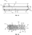
- FIGS. 1C-1D are side section and detailed views, respectively, of a catheter or shaft 100c configured in accordance with an embodiment of the present disclosure.
- the catheter or shaft 100c may be configured to be a distal access support catheter (e.g., for supporting other catheters, including delivery catheters, intravascular devices, or both) and/or aspiration catheter as described herein.
- the slotted portion 116 includes a first segment S1 with a first pattern of slotted openings 126 and a second segment S2 extending proximally (e.g., disposed proximal) relative the first segment S1 with a second pattern of slotted openings 132 different from the first pattern 126.
- the slotted openings 118 are discontinuous (e.g., do not extend circumferentially around the shaft 110 in a continuous manner or 360 degrees).
- the slotted openings 118 include cut and uncut portions (e.g., slotted and un-slotted, removed and solid, or grooved and un-grooved portions) as described in more detail below.
- the slotted portion 116 may include more than two slotted segments.
- the slotted portion 116 may include three, four, five, or more slotted segments.
- Each of the segments may have different patterns relative to the other segments.
- two or more of the segments may have similar or the same pattern.
- each of the segments may have one or more patterns (e.g., different patterns) of slotted openings.
- segment S1 may have a first pattern of slotted openings (e.g., along a distal portion) and a second pattern of slotted opening (e.g., along a proximal portion) different from the first pattern (See FIG. 1I ).
- the segment S2 may then have a third pattern of slotted openings and/or fourth pattern of slotted openings different from the pattern(s) of the first segment S1.
- at least one of the pattern(s) of the segment S2 may the same as at least one of the pattern(s) of segment S1.
- the first pattern of slotted openings 126 includes a repeating helical pattern of cut and uncut portions 126a and 126b extending circumferentially around and along a length of the first segment S1.
- the second pattern of slotted openings 132 includes a repeating helical pattern of cut and uncut portions 132a and 132b extending circumferentially around and along a length of the second segment S2.
- the cut and uncut portions of each pattern may extend at equivalent angles (e.g., oblique or orthogonal) relative to the longitudinal axis of the shaft 110.
- a longitudinal spacing between the slotted openings 118 may be closer or smaller at a distal portion (e.g., along segment S1) of the shaft relative to a proximal portion (e.g., along segment S2) such that the openings are more densely packed along the distal portion (e.g., more material removed in that portion) resulting in greater flexibility along the distal portion relative the proximal portion.
- the distal portion e.g., S1 is provided with sufficient flexibility to traverse turns or bends within a patient's vasculature and sufficient length to reach a desired location within the patient.
- a length of such a distal portion may be increased proportionally relative to how distal a location the catheter is to be positioned within the patient.
- the proximal portion e.g., S2
- the proximal portion is provided with sufficient rigidity such that push-pull forces applied to the proximal end may be transferred to advance the catheter therethrough.
- the proximal end 112 includes a solid or uncut portion 122 (e.g., un-slotted) extending proximally relative to segment S2 and the distal end 114 includes a solid or uncut portion 124 (e.g., un-slotted) extending distally relative to segment S1.
- the proximal solid portion 122 may have a length with values of or between .01" to .02", .012" to .018", .014" to .016", or any value therebetween (e.g., .014").
- the distal solid portion 124 may have a length with values of or between .001" to .006", .002" to .005", .003" to .004", or any value therebetween (e.g., .0031").
- a pitch or spacing between cut portions may vary or increase from pitch P1 at a distal end to pitch P2 at the proximal end of the slotted portion.
- a longitudinal spacing or pitch P1 between cut portions 126a of the first pattern 126 may be smaller relative to the longitudinal spacing or pitch P2 (e.g., P1 ⁇ P2) between cut portions 132a of the second pattern 132 such that a density or number of slotted openings in the first segment S1 is greater than a density or number of slotted openings in the second segment S2 (e.g., providing greater relative flexibility).
- the longitudinal spacing or pitch between uncut portions 126b of the first pattern 126 may be smaller relative to the longitudinal spacing or pitch between uncut portions 132b of the second pattern 132.
- the pitch or spacing may be constant along a segment or segments.
- the longitudinal spacing or pitch along a length of the shaft 110 gradually or progressively increases from the distal end 114 to the proximal end 112 (e.g., from distal end of the first pattern 126 to a proximal end of the second pattern 132) such that it varies across each segment.
- pitch may progressively increase along the length of one or more segments rather than being constant across segments such that the pitch or longitudinal spacing transitions from pitch P1 to pitch P2 along the length of the shaft.
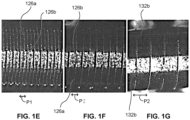
- the pitch or longitudinal spacing between cut portions between the distal and proximal ends may have a value greater than P1 but less than P2. For example, as illustrated in detailed views ( FIGS.
- the pitch or longitudinal spacing may vary or progressively increase along a length of the slotted portion of the shaft from pitch P1 at a distal portion ( FIG. 1E ), to pitch PI at an intermediary portion between distal and proximal portions ( FIG. 1F ), and to pitch P2 at a proximal portion ( FIG. 1G ).
- the distal, intermediary, and proximal portions may correspond to locations about 1", 6", and 47", respectively, from a distal end of a shaft having an overall length of about 50" (e.g., with segment S1 of about 10" and S2 about 40".
- these locations may correspond to locations proximate or near a distal end of segment S1, proximal end of segment S1, and proximal end of segment S2, respectively.
- the pitch or longitudinal spacing may transition from a first pitch P1 to a second pitch P2 along the length of the segment S1, and then to a pitch P3 at segment S2 (e.g., a proximal end of segment S2).
- pitch may progressively increase along the length of an individual segment rather than being constant across the entirety of the segment.
- the pitch P1 may have a value of or between .001" to .006", .002" to .005", .003" to .004", or any value therebetween (e.g., .0031").
- the pitch P2 may have a value of or between .01" to .02", .012" to .018", .014" to .016", or any value there between (e.g., .015").
- the repeating helical patterns of the first pattern or second pattern include cut and uncut portions. Each cut portion is spaced circumferentially from another cut portion by an uncut portion such that the repeating helical pattern includes alternating cut and uncut portions extending circumferentially around the shaft of each slotted segment.
- an arc length of cut portions has a value of or between 80 degrees to 150 degrees or any value therebetween (e.g., 124, 116 degrees, 104 degrees).
- an arc length of uncut portions has a value of or between 10 degrees to 60 degrees or any value therebetween (e.g., 20 degrees, 28 degrees, 40 degrees).
- a combined arc length of adj acent cut and uncut portions of the helical pattern of the first pattern or second pattern of slotted openings has a value of or between 100 degrees and 180 degrees, 120 degrees to 160 degrees, 130 degrees to 150 degrees, 135 degrees to 145 degrees, or any value therebetween (e.g., 144 degrees).
- the term “cuts per revolution” or “CPR” refers to the number of combined adjacent cut and uncut portions required to completely extend around the shaft 110 (e.g., in one revolution or 360 degrees) determined based on the combined arc length of the adjacent cut and uncut portions. For example, when adjacent cut and uncut portions of the first pattern or second pattern of slotted openings 126 or 132 have a combined arc length of 144 degrees (e.g., 124 degrees cut portion arc length and 20 degrees uncut portion arc length or 116 degrees cut portion arc length and 28 degrees uncut portion arc length), the CPR is 2.5. That is, the product of 2.5 and the combined arc length is equivalent to a single, complete revolution around the shaft (e.g., 360 degrees).
- segments S1 and S2 may have equivalent CPR's. However, in other embodiments, they may be different. In some embodiments, the CPR of a segment may have a value of or between 1-8, 2-7, 3-6, 4-5, 2-3, 2-4, or any value therebetween.
- first and second segments S1 and S2 may each have CPR's of 2.5 or a combined arc length of cut and uncut portions of 144 degrees.
- first segment S1 may have cut portions with arc lengths of 124 degrees and uncut portions with arc lengths of 20 degrees while the segment S2 may have cut portions with arc lengths of 116 degrees and uncut portions with arc lengths of 28 degrees.
- Increasing arc length of cut portions in segment S1 relative to arc length of cut portions in segment S2 may increase flexibility (e.g., varying flexibility along the length) in the segment instead of or in addition to decreasing pitch or longitudinal spacing (e.g., increasing density of slotted opening). In this manner, segment S1 is also more flexible as the arc length of its cut portions are relatively greater than the arc length of the cut portions of the segment S2.
- one or more of CPR or combined arc length of cut and uncut portions, pitch, width, arc length of cut portions, or arc length of uncut portions may be varied or constant across each segment or segments.
- the varying arc length and spacing as described herein may also provide the catheter or shaft 100 with sufficient flexibility or structural integrity (e.g., to prevent or reduce ovalizing or kinking) while improving dimensional characteristics of the catheter or shaft 100c (e.g., reduced outer diameter or wall thickness or increased inner diameter) relative to conventional catheters as described in more detail below.
- segments of the catheter or shaft 100 may be characterized by one or more respective cut patterns.
- the term "cut pattern" refers to the ratio of the cut portion arc length to the uncut portion arc length.
- a cut pattern of 124/20 indicates a cut portion arc length of 124 degrees and an uncut portion arc length of 20 degrees. This may be expressed with less specificity as having a CPR of 2.5, as discussed above.
- the cut pattern may vary gradually or progressively along the length of the catheter or shaft 100. In some embodiments, the cut pattern may progressively decrease from the distal end 114 to the proximal end 112. In some embodiments, as with pitch, the cut pattern may progressively decrease within an individual segment. Increasing the cut pattern increases flexibility. For example, a cut pattern of 124/20 provides for a relatively flexible segment of the catheter shaft 100, while a cut pattern of 79/65 provides for a relatively rigid segment.
- both the cut pattern and the pitch may vary gradually or progressively across the length of the catheter or shaft 100.
- the cut pattern and/or pitch may be varied to affect the local flexibility (or rigidity) of a segment of the catheter or shaft 100. Abrupt transitions in flexibility may have the undesired effect of compromising the integrity of the catheter or shaft 100, or of increasing the risk of kinking (e.g., at the juncture between two segments of different flexibility). Varying the transition gradually or progressively serves to prevent or reduce these undesired effects.
- varying both cut pattern and pitch may allow for a smoother transition between segments. For example, to achieve a desired flex ability, the cut pattern and the pitch may each be varied by a relatively small amount.
- FIG. 1J illustrates an example of one or more segments of the catheter or shaft 100 having a progressively varying pitch and a progressively varying cut pattern.
- the segment S 1 may have a pitch that progressively varies from P1 to P2 (e.g., 0.0025" to 0.010") and a cut pattern that progressively varies from C1 to C2 (e.g., 124/20 to 99/45).
- the segment S2 may have a constant pitch P2 (e.g., 0.010") and a constant cut pattern C2 (e.g., 99/45).
- the segment S3 may have a constant pitch of P2 (e.g., 0.010") and a cut pattern that progressively varies from C2 to C3 (e.g., 99/45 to 79/65).
- FIG. 1K illustrates an example embodiment of a catheter or shaft having three distinct segments.
- Each of these segments-S1, S2, and S3- may have different pitch, cut pattern, CPR, and lengths, as outlined in the table below, listing different embodiments ("items").
- item 1 is an embodiment that has a segment S 1 that has a length of 30 cm, a varying pitch that varies (e.g., progressively) from 0.0027" to 0.010", a cut pattern that that varies (e.g., progressively) from 124/20 to 104/40, and a CPR of 2.5.
- item 1 also has a segment S2 that has a length of 135 cm and a segment S3 that has a length of 0.025 cm (or 0.010").
- segments S2 and S3 are not slotted.
- S1 S2 S3 Item Length Pitch Cut Pattern CPR Length Pitch Cut Pattern CPR Length Pitch Cut Pattern CPR Length Pitch Cut Pattern CPR 1 30 cm 0.0027" ⁇ 0.010" 124/20 ⁇ 104/40 2.5 135 cm N/A N/A N/A .010" (.025 cm) N/A N/A N/A 2 30 cm 0.0027" ⁇ 0.010" 124/20 ⁇ 104/40 2.5 135 cm .010" 104/40 2.5 .010" (.025 cm) N/A N/A N/A 3 40 cm 0.0025" ⁇ 0.010" 124/20 ⁇ 99/45 2.5 118 cm 0.010" 99/45 2.5 10 cm 0.010" 99/45
- the catheter or shaft 100c has an outer diameter OD having a value of or between about .02" to .12", .04" to .09” or any value therebetween (e.g., .06", .065", .07”).
- the OD may be constant or uniform in some embodiments across the length.
- the catheter or shaft 100c may have an inner diameter ID having a value of or between .02" to .08” or any value therebetween (e.g., .06", .061", .062", .072").
- the ID may be constant or uniform in some embodiments across the length.
- a wall thickness T of catheter or shaft 100c may have a value of or between .001" to .005", less than .003", or any value therebetween (e.g., .0015", .002", .003", .0035", .004").
- the catheter or shaft 100c may have an overall length L of or between 30 to 80 inches, or any value therebetween (e.g., 45", 50", 55").
- Segment S1 may have a length L of or between 5 to 20 inches, or any value therebetween (e.g., 5", 10").
- Segment S2 may have a length L of or between 25 to 75 inches, or any value therebetween (e.g., 40", 45", 50").
- the proximal end 112 of the catheter or shaft 100c may be operably coupled to a catheter control handle 120a, fluid source 120b, aspiration source 120c, or energy delivery source.
- the shaft 110 may include outer or inner layers or jackets 140, 142 (e.g., Teflon, polyurethane, polyether, elastomer, PTFE, polymer or other suitable material liners, layers, coatings) sandwiching the shaft therebetween (e.g., to reduce friction against a patient's vasculature or catheters or other devices supported therein).
- the outer or inner layers or jackets 140, 142 may include a hydrophilic or anti-thrombogenic coating.
- the catheter or shaft 100c does not include an inner jacket 142.
- an inner liner or coating may not be provided when the catheter is used directly as a delivery shaft for a mechanical thrombectomy device, as an aspiration catheter to increase inner diameter, or when other catheters or devices are not configured to move therethrough.
- One or more of the outer or inner layers or jackets 140, 142 may be directly applied, adhered, coated, or otherwise coupled to the shaft 110 (e.g., without intermediary, strike, or adhesive layers therebetween).
- the inner or outer layer or jacket e.g., liner
- the inner or outer layer or jacket may have a width or thickness of or between .00025" to .002", or any value therebetween (e.g., .001").
- the shaft 110 may be provided with an outer jacket 140 having a uniform hardness across its length (e.g., reducing overall profile).
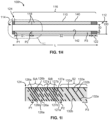
- the catheter or shaft 100h may be configured to be a delivery catheter or shaft (e.g., coupled to the intravascular device) for directly supporting or positioning an intravascular device such as a thrombectomy or filter device as described in U.S. Provisional Application Nos. 62/677,870 and 62/697,644 ) as described herein.
- the catheter or shaft 100h may include one or more of any of the features, in whole or in part, as described above with respect to catheter or shaft 100c.
- the catheter or shaft 100h includes a slotted portion 116.
- the slotted portion 116 includes a first segment S1 with a first pattern of slotted openings 126 (e.g., along a distal portion S1A) and a second pattern of slotted openings 127 different from the first pattern (e.g., reduced arc length of cut portions relative to the first pattern along a proximal portion S2A).
- the slotted portion further includes a second segment S2 extending proximally (e.g., disposed proximal) relative the first segment S1 with a third pattern of slotted openings 132 different from the first pattern 126 (e.g., either the same as the second pattern 127 or reduced arc length of cut portions relatively to the second pattern).
- segment S2 is solid or uncut and does not include a pattern of slotted openings 118.
- segment S1 or other segments only include one pattern (e.g., the first pattern of slotted openings 126).
- the slotted openings 118 are discontinuous (e.g., do not extend circumferentially around the shaft 110 in a continuous manner or 360 degrees).
- the proximal end 112 of the catheter or shaft 100h may be operably coupled to a catheter control handle 120a, fluid source 120b, aspiration source 120c, or energy delivery source.
- the proximal end 112 includes a solid or uncut portion 122 (e.g., un-slotted) extending proximally relative to segment S2 and the distal end 114 includes a solid or uncut portion 124 (e.g., un-slotted) extending distally relative to segment S1.
- the proximal solid portion 122 may have a length with values of or between .005" to .03", .01" to .02", or any value there between (e.g., .01").
- the distal solid portion 124 may have a length with values of or between .001" to .006", .002" to .005", .003" to .004", or any value therebetween (e.g., .0027").
- longitudinal spacing or pitch may increase from a distal end to a proximal end of the slotted shaft.
- the longitudinal spacing or pitch P1 between cut portions 126a of the first pattern 126 may be smaller relative to the longitudinal spacing or pitch P2 (e.g., P1 ⁇ P2) between cut portion 127a of the second pattern of segment S1 as well as longitudinal spacing or pitch P3 between cut portions 132a of the third pattern 132 such that a density or number of slotted openings in a distal portion of first segment S1 is greater than a density or number of slotted openings in the proximal portion of first segment S1 or the second segment S2 (e.g., to provide flexibility for traversing bends while maintaining sufficient stiffness along a proximal portion for application or transferring of push-pull forces).
- P2 is less than P3. In other embodiments P2 is equivalent or equals P3. Similarly, the longitudinal spacing or pitch between uncut portions 126b of the first pattern 126 may be smaller relative to the longitudinal spacing or pitch between uncut portions 127b or 132b.
- the pitch P1 has a value of or between .001" to .006", .002" to .005", .003" to .004", or any value therebetween (e.g., .0027").
- the pitches P2 or P3 has a value of or between .005" to .03", .01" to .02", or any value therebetween (e.g., .01").
- the longitudinal spacing or pitch along a length of the shaft 110 of catheter or shaft 100h may gradually or progressively increase from the distal end 114 to the proximal end 112 (e.g., from distal end of the first pattern 126 to the second pattern 127 and then to the proximal end of the third pattern 132.
- pitch or spacing may progressively increase along the length of one or more segments rather than being constant across segments such that the pitch or longitudinal spacing transitions from pitch P1 to pitch P2 to pitch P3 along the length of the shaft.
- one or more segments may have constant pitches or longitudinal spacing.
- the repeating helical patterns of the first pattern, second pattern, or third pattern include cut and uncut portions.
- an arc length of cut portions has a value of or between 80 degrees to 150 degrees or any value therebetween (e.g., 124, 116 degrees, 104 degrees).
- an arc length of uncut portions has a value of or between 10 degrees to 60 degrees or any value therebetween (e.g., 20 degrees, 28 degrees, 40 degrees).
- a combined arc length of adjacent cut and uncut portions of the helical pattern of the first pattern or second pattern of slotted openings has a value of or between 100 degrees and 180 degrees, 120 degrees to 160 degrees, 130 degrees to 150 degrees, 135 degrees to 145 degrees, or any value therebetween (e.g., 144 degrees).
- segments S1 and S2 e.g., first pattern, second pattern, and third pattern of slotted openings 126, 127 and 132
- one or more of the patterns may have different CPR's.
- CPR or combined arc length of cut and uncut portions may be constant across each segment or segments, pitch, length, arc lengths of cut portions, or arc lengths of uncut portions may be different or varied across each segment or segments.
- the first and second segments may each have CPR's of 2.5 or a combined arc length of cut and uncut portions of 144 degrees.
- the first segment S1 may have cut portions with arc lengths of 124 degrees and uncut portions with arc lengths of 20 degrees while the segment S2 may have cut portions with arc lengths of 104 degrees and uncut portions with arc lengths of 40 degrees.
- a segment (e.g., first segment S1) may have cut portions with arc lengths of 124 degrees and uncut portions with arc lengths of 20 degrees along a distal portion and cut portion with arc lengths of 104 degrees and uncut portions with arc lengths of 40 degrees along a proximal portion.
- one or more of CPR or combined arc length of cut and uncut portions, pitch, width, arc length of cut portions, or arc length of uncut portions may be varied or constant across each segment or segments.
- the catheter or shaft 100h has an outer diameter OD having a value of or between about .02" to .12", .01” to .03” or any value therebetween (e.g., .016", .018", .02").
- the catheter or shaft 100h may have an inner diameter ID having a value of or between .01" to .03” or any value therebetween (e.g., .012", .014", .016").
- a wall thickness T of catheter or shaft 100h may have a value of or between .001" to .005", less than .003", or any value therebetween (e.g., .0015", .002", .003", .0035", .004").
- the catheter or shaft 100h may have an overall length L of or between 40 to 80 inches, or any value therebetween (e.g., 60", 65", 70"). Segment S1 may have a length L of or between 5 to 20 inches, or any value therebetween (e.g., 9", 11". 13"). Segment S2 may have a length L of or between 35 to 75 inches, or any value therebetween (e.g., 50", 55", 60"). In some embodiments, one or more of OD, ID, or T may be uniform across the length.
- the catheter or shaft 100h may have inner and outer layer or jackets 140, 142 as described above (e.g., with uniform hardness or directly coupled), be formed without an inner layer or jacket 142, and/or without a coil or braid.
- FIGS. 5A-5B illustrate exemplary methods 500a and 500b for positioning a distal access support catheter within a vasculature of a patient and aspirating an obstruction from a vasculature of a patient, respectively.
- the method 500a includes the steps of advancing a distal access support catheter into a patient 502a (e.g., via a guidewire or within an outer catheter or sheath).
- the distal access support catheter includes a flexible and hollow shaft including a proximal end and a distal end as described herein.
- the shaft includes a slotted portion with a plurality of slotted openings and the slotted portion includes a first segment with a first pattern of slotted openings and a second segment extending proximally relative the first segment with a second pattern of slotted openings different from the first pattern.
- the method 500a further includes bending the slotted portion of the shaft in at least two spaced apart locations while advancing the catheter through the vasculature of the patient 504a.
- the method 500b includes advancing an aspiration catheter into a patient distally of an obstruction 502b (e.g., via a guidewire or within an outer catheter or sheath).
- the aspiration catheter includes a flexible and hollow shaft including a proximal end and a distal end.
- the shaft includes a slotted portion with a plurality of slotted openings and the slotted portion includes a first segment with a first pattern of slotted openings and a second segment extending proximally relative the first segment with a second pattern of slotted openings different from the first pattern.
- the method further includes bending the slotted portion of the shaft in at least two spaced apart locations while advancing the catheter through the vasculature of the patient 504b.
- the method also includes aspirating the obstruction out of the patient through the shaft 506b.
- FIG. 5C illustrates an exemplary method 500c for manufacturing a distal access support and/or aspiration catheter as described herein.
- the method 500c includes the steps of cutting a first pattern of slotted openings in a first segment of an elongated, hollow shaft 502c.
- the method further includes cutting a second pattern of slotted openings in a second segment of the elongated, hollow shaft, the second segment extending proximally relative the first segment, and the second pattern of slotted openings different from the first pattern of slotted openings 504c.
Landscapes
- Health & Medical Sciences (AREA)
- Life Sciences & Earth Sciences (AREA)
- Heart & Thoracic Surgery (AREA)
- Animal Behavior & Ethology (AREA)
- Veterinary Medicine (AREA)
- Public Health (AREA)
- Engineering & Computer Science (AREA)
- Biomedical Technology (AREA)
- General Health & Medical Sciences (AREA)
- Anesthesiology (AREA)
- Hematology (AREA)
- Surgery (AREA)
- Biophysics (AREA)
- Pulmonology (AREA)
- Vascular Medicine (AREA)
- Orthopedic Medicine & Surgery (AREA)
- Nuclear Medicine, Radiotherapy & Molecular Imaging (AREA)
- Medical Informatics (AREA)
- Molecular Biology (AREA)
- Surgical Instruments (AREA)
- Media Introduction/Drainage Providing Device (AREA)
Applications Claiming Priority (3)
| Application Number | Priority Date | Filing Date | Title |
|---|---|---|---|
| US201862701254P | 2018-07-20 | 2018-07-20 | |
| US201962858835P | 2019-06-07 | 2019-06-07 | |
| PCT/US2019/041030 WO2020018319A1 (en) | 2018-07-20 | 2019-07-09 | Neurovascular distal access support catheters, aspiration catheters, or device shafts |
Publications (3)
| Publication Number | Publication Date |
|---|---|
| EP3823523A1 EP3823523A1 (en) | 2021-05-26 |
| EP3823523A4 EP3823523A4 (en) | 2022-05-18 |
| EP3823523B1 true EP3823523B1 (en) | 2024-07-31 |
Family
ID=69160936
Family Applications (1)
| Application Number | Title | Priority Date | Filing Date |
|---|---|---|---|
| EP19837373.0A Active EP3823523B1 (en) | 2018-07-20 | 2019-07-09 | Neurovascular distal access support catheters, aspiration catheters, or device shafts |
Country Status (5)
| Country | Link |
|---|---|
| US (3) | US11383068B2 (https=) |
| EP (1) | EP3823523B1 (https=) |
| JP (1) | JP2021531866A (https=) |
| CN (1) | CN112638240A (https=) |
| WO (1) | WO2020018319A1 (https=) |
Families Citing this family (15)
| Publication number | Priority date | Publication date | Assignee | Title |
|---|---|---|---|---|
| US11771875B2 (en) | 2017-03-02 | 2023-10-03 | CereVasc, Inc. | Catheter systems and methods for medical procedures using catheters |
| CN112638317B (zh) | 2018-05-30 | 2024-07-02 | 艾露姆技术股份有限公司 | 集成的血栓切除和过滤装置及其使用方法 |
| JP2021531866A (ja) * | 2018-07-20 | 2021-11-25 | イーラム テクノロジーズ,インコーポレイテッド | 神経血管末梢アクセス支援カテーテル、吸引カテーテル、またはデバイスシャフト |
| US11865237B2 (en) | 2020-04-20 | 2024-01-09 | Surmodics Md, Llc | Radial balloon catheter |
| US11679195B2 (en) | 2021-04-27 | 2023-06-20 | Contego Medical, Inc. | Thrombus aspiration system and methods for controlling blood loss |
| WO2022261043A1 (en) | 2021-06-07 | 2022-12-15 | Avantec Vascular Corporation | Hybrid atherectomy devices |
| DE102022124478A1 (de) * | 2021-10-01 | 2023-04-06 | Gyrus Acmi, Inc. D/B/A Olympus Surgical Technologies America | Nadel mit zusammenhängenden unterbrochenen und ununterbrochenen schraubenförmig geschnittenen abschnitten |
| WO2024026462A2 (en) * | 2022-07-29 | 2024-02-01 | Maduro Discovery, Llc | Slotted liners for medical device |
| EP4410349A1 (en) * | 2023-02-03 | 2024-08-07 | Imds R&D Bv | A microcatheter for interventional cardiovascular and/or neurovascular applications |
| WO2025038964A1 (en) | 2023-08-16 | 2025-02-20 | Avantec Vascular Corporation | Thrombectomy devices with lateral and vertical bias |
| CN117064490A (zh) * | 2023-08-29 | 2023-11-17 | 融冲(深圳)生物医疗科技有限责任公司 | 抽吸导管 |
| WO2025128825A1 (en) * | 2023-12-13 | 2025-06-19 | Boston Scientific Scimed, Inc. | Intravascular imaging catheter |
| CN117861041B (zh) * | 2024-01-09 | 2024-07-16 | 上海心玮医疗科技股份有限公司 | 一种微导管 |
| US20250262411A1 (en) * | 2024-02-15 | 2025-08-21 | DeepIn Technologies, LLC | Intravascular medical devices including laser cut tube |
| US12414785B1 (en) | 2025-03-17 | 2025-09-16 | Avantec Vascular Corporation | Cutters with pulsating vacuum control |
Citations (1)
| Publication number | Priority date | Publication date | Assignee | Title |
|---|---|---|---|---|
| US8728116B1 (en) * | 2013-07-29 | 2014-05-20 | Insera Therapeutics, Inc. | Slotted catheters |
Family Cites Families (102)
| Publication number | Priority date | Publication date | Assignee | Title |
|---|---|---|---|---|
| JPH02295569A (ja) | 1989-04-25 | 1990-12-06 | C R Bard Inc | ガイドワイヤ |
| EP1221307B1 (en) | 1994-07-08 | 2010-02-17 | ev3 Inc. | System for performing an intravascular procedure |
| JPH08308933A (ja) * | 1995-05-22 | 1996-11-26 | Piolax Inc | 医療用チューブ |
| US5827304A (en) | 1995-11-16 | 1998-10-27 | Applied Medical Resources Corporation | Intraluminal extraction catheter |
| US6036707A (en) * | 1996-03-07 | 2000-03-14 | Devices For Vascular Intervention | Catheter device having a selectively flexible housing |
| WO1997038631A1 (en) | 1996-04-18 | 1997-10-23 | Applied Medical Resources Corporation | Remote clot management |
| US6066158A (en) | 1996-07-25 | 2000-05-23 | Target Therapeutics, Inc. | Mechanical clot encasing and removal wire |
| AT404123B (de) | 1996-11-06 | 1998-08-25 | Lager Technik Gmbh | Fahrzeug insbesondere für innerbetriebliche transportsysteme |
| EP0934092A4 (en) | 1997-03-06 | 2008-03-26 | Boston Scient Scimed Inc | DEVICE AND METHOD FOR DISTAL PROTECTION |
| US6258115B1 (en) | 1997-04-23 | 2001-07-10 | Artemis Medical, Inc. | Bifurcated stent and distal protection system |
| US5944730A (en) | 1997-05-19 | 1999-08-31 | Cardio Medical Solutions, Inc. | Device and method for assisting end-to-side anastomosis |
| JP4328888B2 (ja) | 1997-11-07 | 2009-09-09 | サルヴィアック・リミテッド | 塞栓防止器具 |
| DE69839888D1 (de) | 1997-11-12 | 2008-09-25 | Genesis Technologies Llc | Vorrichtung zum entfernen von okklusionen in biologischen durchgängen |
| US20040260333A1 (en) | 1997-11-12 | 2004-12-23 | Dubrul William R. | Medical device and method |
| US20040199202A1 (en) | 1997-11-12 | 2004-10-07 | Genesis Technologies Llc | Biological passageway occlusion removal |
| US20100030256A1 (en) | 1997-11-12 | 2010-02-04 | Genesis Technologies Llc | Medical Devices and Methods |
| US9498604B2 (en) | 1997-11-12 | 2016-11-22 | Genesis Technologies Llc | Medical device and method |
| US6273876B1 (en) * | 1997-12-05 | 2001-08-14 | Intratherapeutics, Inc. | Catheter segments having circumferential supports with axial projection |
| JP2002502626A (ja) | 1998-02-10 | 2002-01-29 | アーテミス・メディカル・インコーポレイテッド | 補足装置およびその使用方法 |
| JP2003522550A (ja) | 1998-02-10 | 2003-07-29 | アーテミス・メディカル・インコーポレイテッド | 咬合、固定、テンショニング、及び流向装置とその使用方法 |
| US6450989B2 (en) | 1998-04-27 | 2002-09-17 | Artemis Medical, Inc. | Dilating and support apparatus with disease inhibitors and methods for use |
| US6511492B1 (en) | 1998-05-01 | 2003-01-28 | Microvention, Inc. | Embolectomy catheters and methods for treating stroke and other small vessel thromboembolic disorders |
| US20020169474A1 (en) | 1999-03-08 | 2002-11-14 | Microvena Corporation | Minimally invasive medical device deployment and retrieval system |
| CA2336416A1 (en) * | 1999-04-30 | 2000-11-09 | Gono Usami | Catheter and guide wire |
| US6530939B1 (en) | 1999-07-30 | 2003-03-11 | Incept, Llc | Vascular device having articulation region and methods of use |
| US20020026211A1 (en) | 1999-12-23 | 2002-02-28 | Farhad Khosravi | Vascular device having emboli and thrombus removal element and methods of use |
| US6589263B1 (en) | 1999-07-30 | 2003-07-08 | Incept Llc | Vascular device having one or more articulation regions and methods of use |
| US6168579B1 (en) | 1999-08-04 | 2001-01-02 | Scimed Life Systems, Inc. | Filter flush system and methods of use |
| ES2311670T3 (es) | 1999-08-27 | 2009-02-16 | Ev3 Inc. | Filtro vascular deslizante. |
| US7727242B2 (en) | 2000-06-29 | 2010-06-01 | Concentric Medical, Inc. | Systems, methods and devices for removing obstructions from a blood vessel |
| US6773446B1 (en) * | 2000-08-02 | 2004-08-10 | Cordis Corporation | Delivery apparatus for a self-expanding stent |
| JP2002246281A (ja) | 2001-02-13 | 2002-08-30 | Mitsubishi Electric Corp | 半導体装置の製造方法およびそれに用いられるレチクル並びにウェハ |
| US6635070B2 (en) | 2001-05-21 | 2003-10-21 | Bacchus Vascular, Inc. | Apparatus and methods for capturing particulate material within blood vessels |
| US6878151B2 (en) | 2001-09-27 | 2005-04-12 | Scimed Life Systems, Inc. | Medical retrieval device |
| US6755847B2 (en) | 2001-10-05 | 2004-06-29 | Scimed Life Systems, Inc. | Emboli capturing device and method of manufacture therefor |
| US20030144686A1 (en) | 2002-01-30 | 2003-07-31 | Embol-X, Inc. | Distal filtration devices and methods of use during aortic procedures |
| WO2003092765A2 (en) | 2002-05-02 | 2003-11-13 | Dubrul William R | Upper airway device and method |
| US7115134B2 (en) * | 2002-07-22 | 2006-10-03 | Chambers Technology, Llc. | Catheter with flexible tip and shape retention |
| US7056328B2 (en) | 2002-09-18 | 2006-06-06 | Arnott Richard J | Apparatus for capturing objects beyond an operative site utilizing a capture device delivered on a medical guide wire |
| ITBS20020107A1 (it) * | 2002-11-25 | 2004-05-26 | Invatec Srl | Tubo metallico con almeno una parte di lunghezza a flessibilita' variabile. |
| US7766973B2 (en) | 2005-01-19 | 2010-08-03 | Gi Dynamics, Inc. | Eversion resistant sleeves |
| WO2004093966A1 (en) | 2003-04-16 | 2004-11-04 | Genesis Technologies Llc. | Medical device and method |
| JP4731471B2 (ja) | 2003-04-16 | 2011-07-27 | ジェネシス・テクノロジーズ・エルエルシー | 医療機器と方法 |
| US7354445B2 (en) | 2003-12-15 | 2008-04-08 | Medtronic Vascular Inc. | Embolic containment system with asymmetric frictional control |
| US7637903B2 (en) * | 2004-02-09 | 2009-12-29 | Cryocor, Inc. | Catheter articulation segment with alternating cuts |
| MX2009004020A (es) | 2004-03-04 | 2009-04-27 | Cabezal de trabajo de un cateter para aspirar, fragmentar y extraer material extirpable de vasos sanguineos. | |
| US20160022293A1 (en) | 2004-04-15 | 2016-01-28 | Genesis Technologies Llc | Medical device and method |
| US7374553B2 (en) * | 2004-06-24 | 2008-05-20 | Cryocor, Inc. | System for bi-directionally controlling the cryo-tip of a cryoablation catheter |
| US8109962B2 (en) | 2005-06-20 | 2012-02-07 | Cook Medical Technologies Llc | Retrievable device having a reticulation portion with staggered struts |
| US20080188793A1 (en) * | 2007-02-06 | 2008-08-07 | Possis Medical, Inc. | Miniature flexible thrombectomy catheter |
| JP5164861B2 (ja) | 2006-02-01 | 2013-03-21 | ザ クリーブランド クリニック ファウンデーション | ふさがれた血管を通る血流を増加させる方法と装置 |
| US9345509B2 (en) * | 2006-02-22 | 2016-05-24 | Baylis Medical Company Inc. | Guide-wire dilation device for facilitation of lesion crossing |
| US20070288054A1 (en) | 2006-06-13 | 2007-12-13 | Tanaka Don A | Vascular thrombectomby apparatus and method of use |
| US20090018566A1 (en) | 2006-06-30 | 2009-01-15 | Artheromed, Inc. | Atherectomy devices, systems, and methods |
| US7708704B2 (en) * | 2006-07-31 | 2010-05-04 | Codman & Shurtleff, Pc | Interventional medical device component having an interrupted spiral section and method of making the same |
| US20080097401A1 (en) | 2006-09-22 | 2008-04-24 | Trapp Benjamin M | Cerebral vasculature device |
| ATE485013T1 (de) | 2006-11-20 | 2010-11-15 | Septrx Inc | Vorrichtung zur verhinderung des nicht erwünschten durchflusses der embolis von den venen in die arterien |
| US8556914B2 (en) | 2006-12-15 | 2013-10-15 | Boston Scientific Scimed, Inc. | Medical device including structure for crossing an occlusion in a vessel |
| US10064635B2 (en) | 2007-04-17 | 2018-09-04 | Covidien Lp | Articulating retrieval devices |
| US11202646B2 (en) | 2007-04-17 | 2021-12-21 | Covidien Lp | Articulating retrieval devices |
| US10076346B2 (en) | 2007-04-17 | 2018-09-18 | Covidien Lp | Complex wire formed devices |
| US8535334B2 (en) | 2007-04-17 | 2013-09-17 | Lazarus Effect, Inc. | Complex wire formed devices |
| US8585713B2 (en) | 2007-10-17 | 2013-11-19 | Covidien Lp | Expandable tip assembly for thrombus management |
| US9827084B2 (en) | 2007-10-26 | 2017-11-28 | Embolitech, Llc | Intravascular guidewire filter system for pulmonary embolism protection and embolism removal or maceration |
| CN102036611B (zh) | 2007-12-26 | 2015-01-28 | 拉撒路效应公司 | 取回系统及其使用方法 |
| US8777976B2 (en) | 2008-07-22 | 2014-07-15 | Neuravi Limited | Clot capture systems and associated methods |
| US9011511B2 (en) | 2009-02-20 | 2015-04-21 | Boston Scientific Scimed, Inc. | Balloon catheter |
| WO2010102307A1 (en) | 2009-03-06 | 2010-09-10 | Lazarus Effect, Inc. | Retrieval systems and methods for use thereof |
| US8317251B2 (en) | 2009-05-01 | 2012-11-27 | Nelson Charles R | Removable enclosure for rear of vehicle |
| US8979157B2 (en) | 2009-05-01 | 2015-03-17 | Charles R. Nelson | Removable enclosure for rear of vehicle |
| US20110175391A1 (en) | 2009-05-01 | 2011-07-21 | Nelson Charles R | Removable enclosure for rear of vehicle |
| US8795345B2 (en) | 2009-07-08 | 2014-08-05 | Concentric Medical, Inc. | Vascular and bodily duct treatment devices and methods |
| US8357178B2 (en) | 2009-07-08 | 2013-01-22 | Concentric Medical, Inc. | Vascular and bodily duct treatment devices and methods |
| WO2011091383A1 (en) | 2010-01-22 | 2011-07-28 | Lazarus Effect, Inc. | Retrieval systems and methods for use thereof |
| EP2539012B1 (en) | 2010-02-23 | 2018-01-24 | Covidien LP | Devices for vascular recanalization |
| WO2011130256A2 (en) | 2010-04-13 | 2011-10-20 | Lumen Biomedical, Inc. | Embolectomy devices and methods for treatment of acute ischemic stroke condition |
| US9144665B2 (en) * | 2010-08-09 | 2015-09-29 | Boston Scientific Limited | Flexible sheath assemblies and interventional catheter systems incorporating them |
| ES3029850T3 (en) | 2011-03-09 | 2025-06-25 | Neuravi Ltd | A clot retrieval device for removing occlusive clot from a blood vessel |
| CN103764216B (zh) * | 2011-05-03 | 2016-08-17 | 施菲姆德控股有限责任公司 | 可转向输送护套 |
| CN103841905B (zh) | 2011-05-23 | 2017-04-12 | 柯惠有限合伙公司 | 取出系统及其使用方法 |
| WO2013071173A1 (en) | 2011-11-11 | 2013-05-16 | Dacuycuy Nathan John | Devices for removing vessel occlusions |
| US9603693B2 (en) | 2012-08-10 | 2017-03-28 | W. L. Gore & Associates, Inc. | Dual net vascular filtration devices and related systems and methods |
| US9308007B2 (en) | 2012-08-14 | 2016-04-12 | W. L. Gore & Associates, Inc. | Devices and systems for thrombus treatment |
| EP2897536B1 (en) | 2012-09-24 | 2020-08-19 | Inari Medical, Inc. | Device for treating vascular occlusion |
| US9456834B2 (en) | 2012-10-31 | 2016-10-04 | Covidien Lp | Thrombectomy device with distal protection |
| CA2901443A1 (en) * | 2013-03-15 | 2014-09-25 | Insera Therapeutics, Inc. | Vascular treatment devices and methods |
| US10231751B2 (en) | 2013-05-29 | 2019-03-19 | Thomas A. Sos | Thrombus removal and intravascular distal embolic protection device |
| JP6466419B2 (ja) | 2013-05-29 | 2019-02-06 | トーマス エー. ソス, | 血栓除去および脈管内遠位塞栓保護デバイス |
| US9439664B2 (en) | 2013-05-29 | 2016-09-13 | Thomas A. Sos | Thrombus removal and intravascular distal embolic protection device |
| EP3010427A4 (en) | 2013-06-17 | 2017-02-08 | BiO2 Medical, Inc. | Covered filter catheter apparatus and method of using same |
| US9962177B2 (en) | 2014-01-03 | 2018-05-08 | Legacy Ventures LLC | Clot retrieval system |
| US9968740B2 (en) | 2014-03-25 | 2018-05-15 | Surefire Medical, Inc. | Closed tip dynamic microvalve protection device |
| US10363398B2 (en) * | 2014-10-06 | 2019-07-30 | Sanovas Intellectual Property, Llc | Steerable catheter with flexing tip member |
| HK1243662A1 (zh) * | 2014-11-04 | 2018-07-20 | 祥丰医疗私人有限公司 | 柔韧性渐变的导管支撑框架 |
| CA2986004C (en) | 2015-05-15 | 2020-06-30 | Teleflex Medical Incorporated | Tethered filter assemblies and methods for use thereof |
| EP3397333A4 (en) * | 2016-01-01 | 2019-10-02 | Tractus Vascular, LLC | FLEXIBLE CATHETER |
| JP2018033491A (ja) * | 2016-08-29 | 2018-03-08 | テルモ株式会社 | 医療デバイスおよび処置方法 |
| JP2019187458A (ja) * | 2016-08-29 | 2019-10-31 | テルモ株式会社 | 吸引カテーテルおよび吸引システム並びに処置方法 |
| WO2018112203A1 (en) | 2016-12-14 | 2018-06-21 | eLum Technologies, Inc. | Electrospun stents, flow diverters, and occlusion devices and methods of making the same |
| US9848906B1 (en) | 2017-06-20 | 2017-12-26 | Joe Michael Eskridge | Stent retriever having an expandable fragment guard |
| CN112638317B (zh) | 2018-05-30 | 2024-07-02 | 艾露姆技术股份有限公司 | 集成的血栓切除和过滤装置及其使用方法 |
| JP2021531866A (ja) * | 2018-07-20 | 2021-11-25 | イーラム テクノロジーズ,インコーポレイテッド | 神経血管末梢アクセス支援カテーテル、吸引カテーテル、またはデバイスシャフト |
-
2019
- 2019-07-09 JP JP2021502946A patent/JP2021531866A/ja active Pending
- 2019-07-09 US US16/506,694 patent/US11383068B2/en active Active
- 2019-07-09 CN CN201980048307.XA patent/CN112638240A/zh active Pending
- 2019-07-09 WO PCT/US2019/041030 patent/WO2020018319A1/en not_active Ceased
- 2019-07-09 EP EP19837373.0A patent/EP3823523B1/en active Active
-
2022
- 2022-06-03 US US17/832,191 patent/US11896757B2/en active Active
-
2024
- 2024-01-08 US US18/406,777 patent/US20240139403A1/en active Pending
Patent Citations (1)
| Publication number | Priority date | Publication date | Assignee | Title |
|---|---|---|---|---|
| US8728116B1 (en) * | 2013-07-29 | 2014-05-20 | Insera Therapeutics, Inc. | Slotted catheters |
Also Published As
| Publication number | Publication date |
|---|---|
| US11896757B2 (en) | 2024-02-13 |
| US20220362520A1 (en) | 2022-11-17 |
| US20240139403A1 (en) | 2024-05-02 |
| US20200023164A1 (en) | 2020-01-23 |
| CN112638240A (zh) | 2021-04-09 |
| WO2020018319A1 (en) | 2020-01-23 |
| EP3823523A1 (en) | 2021-05-26 |
| JP2021531866A (ja) | 2021-11-25 |
| US11383068B2 (en) | 2022-07-12 |
| EP3823523A4 (en) | 2022-05-18 |
Similar Documents
| Publication | Publication Date | Title |
|---|---|---|
| EP3823523B1 (en) | Neurovascular distal access support catheters, aspiration catheters, or device shafts | |
| JP7781926B2 (ja) | 累加柔軟性カテーテル支持フレーム | |
| US20130268050A1 (en) | Devices and methods for accessing a cerebral vessel | |
| US7708704B2 (en) | Interventional medical device component having an interrupted spiral section and method of making the same | |
| US20120172798A1 (en) | Devices and methods for accessing a cerebral vessel | |
| US8585643B2 (en) | Balloon catheter and method of manufacture | |
| JP7508190B2 (ja) | 経頸動脈神経血管カテーテル | |
| US20190192828A1 (en) | High-torque guidewires and methods for making and using them | |
| CN107405160B (zh) | 血管介入系统 | |
| EP3990083B1 (en) | A delivery catheter device and a system for accessing the intracranial vasculature | |
| CN111184554A (zh) | 导管装置 | |
| CN114901202A (zh) | 血管再进入导管 | |
| JP2022109240A (ja) | 二重細長部材血塊回収装置のためのシステム及び方法 | |
| HK40023003A (en) | Progressive flexibility catheter support frame | |
| WO2025151531A2 (en) | Systems and methods for treating vascular disease | |
| HK40096068A (zh) | 用於血管内装置的微制造的芯线 | |
| HK40019557A (en) | Catheter device |
Legal Events
| Date | Code | Title | Description |
|---|---|---|---|
| STAA | Information on the status of an ep patent application or granted ep patent |
Free format text: STATUS: THE INTERNATIONAL PUBLICATION HAS BEEN MADE |
|
| PUAI | Public reference made under article 153(3) epc to a published international application that has entered the european phase |
Free format text: ORIGINAL CODE: 0009012 |
|
| STAA | Information on the status of an ep patent application or granted ep patent |
Free format text: STATUS: REQUEST FOR EXAMINATION WAS MADE |
|
| 17P | Request for examination filed |
Effective date: 20210219 |
|
| AK | Designated contracting states |
Kind code of ref document: A1 Designated state(s): AL AT BE BG CH CY CZ DE DK EE ES FI FR GB GR HR HU IE IS IT LI LT LU LV MC MK MT NL NO PL PT RO RS SE SI SK SM TR |
|
| DAV | Request for validation of the european patent (deleted) | ||
| DAX | Request for extension of the european patent (deleted) | ||
| REG | Reference to a national code |
Ref country code: DE Ref legal event code: R079 Free format text: PREVIOUS MAIN CLASS: A61B0005000000 Ipc: A61B0017221000 Ref country code: DE Ref legal event code: R079 Ref document number: 602019056263 Country of ref document: DE Free format text: PREVIOUS MAIN CLASS: A61B0005000000 Ipc: A61B0017221000 |
|
| A4 | Supplementary search report drawn up and despatched |
Effective date: 20220419 |
|
| RIC1 | Information provided on ipc code assigned before grant |
Ipc: A61M 25/06 20060101ALN20220411BHEP Ipc: A61M 25/00 20060101ALI20220411BHEP Ipc: A61M 1/00 20060101ALI20220411BHEP Ipc: A61B 17/221 20060101AFI20220411BHEP |
|
| STAA | Information on the status of an ep patent application or granted ep patent |
Free format text: STATUS: EXAMINATION IS IN PROGRESS |
|
| 17Q | First examination report despatched |
Effective date: 20230609 |
|
| GRAP | Despatch of communication of intention to grant a patent |
Free format text: ORIGINAL CODE: EPIDOSNIGR1 |
|
| STAA | Information on the status of an ep patent application or granted ep patent |
Free format text: STATUS: GRANT OF PATENT IS INTENDED |
|
| RIC1 | Information provided on ipc code assigned before grant |
Ipc: A61M 25/06 20060101ALN20240319BHEP Ipc: A61M 25/00 20060101ALI20240319BHEP Ipc: A61M 1/00 20060101ALI20240319BHEP Ipc: A61B 17/221 20060101AFI20240319BHEP |
|
| INTG | Intention to grant announced |
Effective date: 20240409 |
|
| GRAS | Grant fee paid |
Free format text: ORIGINAL CODE: EPIDOSNIGR3 |
|
| GRAA | (expected) grant |
Free format text: ORIGINAL CODE: 0009210 |
|
| STAA | Information on the status of an ep patent application or granted ep patent |
Free format text: STATUS: THE PATENT HAS BEEN GRANTED |
|
| AK | Designated contracting states |
Kind code of ref document: B1 Designated state(s): AL AT BE BG CH CY CZ DE DK EE ES FI FR GB GR HR HU IE IS IT LI LT LU LV MC MK MT NL NO PL PT RO RS SE SI SK SM TR |
|
| REG | Reference to a national code |
Ref country code: CH Ref legal event code: EP Ref country code: GB Ref legal event code: FG4D |
|
| P01 | Opt-out of the competence of the unified patent court (upc) registered |
Free format text: CASE NUMBER: APP_40812/2024 Effective date: 20240710 |
|
| REG | Reference to a national code |
Ref country code: DE Ref legal event code: R096 Ref document number: 602019056263 Country of ref document: DE |
|
| REG | Reference to a national code |
Ref country code: IE Ref legal event code: FG4D |
|
| REG | Reference to a national code |
Ref country code: LT Ref legal event code: MG9D |
|
| REG | Reference to a national code |
Ref country code: NL Ref legal event code: MP Effective date: 20240731 |
|
| PG25 | Lapsed in a contracting state [announced via postgrant information from national office to epo] |
Ref country code: PT Free format text: LAPSE BECAUSE OF FAILURE TO SUBMIT A TRANSLATION OF THE DESCRIPTION OR TO PAY THE FEE WITHIN THE PRESCRIBED TIME-LIMIT Effective date: 20241202 |
|
| REG | Reference to a national code |
Ref country code: AT Ref legal event code: MK05 Ref document number: 1707731 Country of ref document: AT Kind code of ref document: T Effective date: 20240731 |
|
| PG25 | Lapsed in a contracting state [announced via postgrant information from national office to epo] |
Ref country code: PT Free format text: LAPSE BECAUSE OF FAILURE TO SUBMIT A TRANSLATION OF THE DESCRIPTION OR TO PAY THE FEE WITHIN THE PRESCRIBED TIME-LIMIT Effective date: 20241202 |
|
| PG25 | Lapsed in a contracting state [announced via postgrant information from national office to epo] |
Ref country code: NO Free format text: LAPSE BECAUSE OF FAILURE TO SUBMIT A TRANSLATION OF THE DESCRIPTION OR TO PAY THE FEE WITHIN THE PRESCRIBED TIME-LIMIT Effective date: 20241031 |
|
| PG25 | Lapsed in a contracting state [announced via postgrant information from national office to epo] |
Ref country code: NL Free format text: LAPSE BECAUSE OF FAILURE TO SUBMIT A TRANSLATION OF THE DESCRIPTION OR TO PAY THE FEE WITHIN THE PRESCRIBED TIME-LIMIT Effective date: 20240731 Ref country code: FI Free format text: LAPSE BECAUSE OF FAILURE TO SUBMIT A TRANSLATION OF THE DESCRIPTION OR TO PAY THE FEE WITHIN THE PRESCRIBED TIME-LIMIT Effective date: 20240731 Ref country code: GR Free format text: LAPSE BECAUSE OF FAILURE TO SUBMIT A TRANSLATION OF THE DESCRIPTION OR TO PAY THE FEE WITHIN THE PRESCRIBED TIME-LIMIT Effective date: 20241101 Ref country code: PL Free format text: LAPSE BECAUSE OF FAILURE TO SUBMIT A TRANSLATION OF THE DESCRIPTION OR TO PAY THE FEE WITHIN THE PRESCRIBED TIME-LIMIT Effective date: 20240731 |
|
| PG25 | Lapsed in a contracting state [announced via postgrant information from national office to epo] |
Ref country code: BG Free format text: LAPSE BECAUSE OF FAILURE TO SUBMIT A TRANSLATION OF THE DESCRIPTION OR TO PAY THE FEE WITHIN THE PRESCRIBED TIME-LIMIT Effective date: 20240731 |
|
| PG25 | Lapsed in a contracting state [announced via postgrant information from national office to epo] |
Ref country code: LV Free format text: LAPSE BECAUSE OF FAILURE TO SUBMIT A TRANSLATION OF THE DESCRIPTION OR TO PAY THE FEE WITHIN THE PRESCRIBED TIME-LIMIT Effective date: 20240731 |
|
| PG25 | Lapsed in a contracting state [announced via postgrant information from national office to epo] |
Ref country code: AT Free format text: LAPSE BECAUSE OF FAILURE TO SUBMIT A TRANSLATION OF THE DESCRIPTION OR TO PAY THE FEE WITHIN THE PRESCRIBED TIME-LIMIT Effective date: 20240731 Ref country code: IS Free format text: LAPSE BECAUSE OF FAILURE TO SUBMIT A TRANSLATION OF THE DESCRIPTION OR TO PAY THE FEE WITHIN THE PRESCRIBED TIME-LIMIT Effective date: 20241130 |
|
| PG25 | Lapsed in a contracting state [announced via postgrant information from national office to epo] |
Ref country code: HR Free format text: LAPSE BECAUSE OF FAILURE TO SUBMIT A TRANSLATION OF THE DESCRIPTION OR TO PAY THE FEE WITHIN THE PRESCRIBED TIME-LIMIT Effective date: 20240731 |
|
| PG25 | Lapsed in a contracting state [announced via postgrant information from national office to epo] |
Ref country code: ES Free format text: LAPSE BECAUSE OF FAILURE TO SUBMIT A TRANSLATION OF THE DESCRIPTION OR TO PAY THE FEE WITHIN THE PRESCRIBED TIME-LIMIT Effective date: 20240731 Ref country code: RS Free format text: LAPSE BECAUSE OF FAILURE TO SUBMIT A TRANSLATION OF THE DESCRIPTION OR TO PAY THE FEE WITHIN THE PRESCRIBED TIME-LIMIT Effective date: 20241031 |
|
| PG25 | Lapsed in a contracting state [announced via postgrant information from national office to epo] |
Ref country code: RS Free format text: LAPSE BECAUSE OF FAILURE TO SUBMIT A TRANSLATION OF THE DESCRIPTION OR TO PAY THE FEE WITHIN THE PRESCRIBED TIME-LIMIT Effective date: 20241031 Ref country code: PL Free format text: LAPSE BECAUSE OF FAILURE TO SUBMIT A TRANSLATION OF THE DESCRIPTION OR TO PAY THE FEE WITHIN THE PRESCRIBED TIME-LIMIT Effective date: 20240731 Ref country code: NO Free format text: LAPSE BECAUSE OF FAILURE TO SUBMIT A TRANSLATION OF THE DESCRIPTION OR TO PAY THE FEE WITHIN THE PRESCRIBED TIME-LIMIT Effective date: 20241031 Ref country code: NL Free format text: LAPSE BECAUSE OF FAILURE TO SUBMIT A TRANSLATION OF THE DESCRIPTION OR TO PAY THE FEE WITHIN THE PRESCRIBED TIME-LIMIT Effective date: 20240731 Ref country code: LV Free format text: LAPSE BECAUSE OF FAILURE TO SUBMIT A TRANSLATION OF THE DESCRIPTION OR TO PAY THE FEE WITHIN THE PRESCRIBED TIME-LIMIT Effective date: 20240731 Ref country code: IS Free format text: LAPSE BECAUSE OF FAILURE TO SUBMIT A TRANSLATION OF THE DESCRIPTION OR TO PAY THE FEE WITHIN THE PRESCRIBED TIME-LIMIT Effective date: 20241130 Ref country code: HR Free format text: LAPSE BECAUSE OF FAILURE TO SUBMIT A TRANSLATION OF THE DESCRIPTION OR TO PAY THE FEE WITHIN THE PRESCRIBED TIME-LIMIT Effective date: 20240731 Ref country code: GR Free format text: LAPSE BECAUSE OF FAILURE TO SUBMIT A TRANSLATION OF THE DESCRIPTION OR TO PAY THE FEE WITHIN THE PRESCRIBED TIME-LIMIT Effective date: 20241101 Ref country code: FI Free format text: LAPSE BECAUSE OF FAILURE TO SUBMIT A TRANSLATION OF THE DESCRIPTION OR TO PAY THE FEE WITHIN THE PRESCRIBED TIME-LIMIT Effective date: 20240731 Ref country code: ES Free format text: LAPSE BECAUSE OF FAILURE TO SUBMIT A TRANSLATION OF THE DESCRIPTION OR TO PAY THE FEE WITHIN THE PRESCRIBED TIME-LIMIT Effective date: 20240731 Ref country code: BG Free format text: LAPSE BECAUSE OF FAILURE TO SUBMIT A TRANSLATION OF THE DESCRIPTION OR TO PAY THE FEE WITHIN THE PRESCRIBED TIME-LIMIT Effective date: 20240731 Ref country code: AT Free format text: LAPSE BECAUSE OF FAILURE TO SUBMIT A TRANSLATION OF THE DESCRIPTION OR TO PAY THE FEE WITHIN THE PRESCRIBED TIME-LIMIT Effective date: 20240731 |
|
| PG25 | Lapsed in a contracting state [announced via postgrant information from national office to epo] |
Ref country code: DK Free format text: LAPSE BECAUSE OF FAILURE TO SUBMIT A TRANSLATION OF THE DESCRIPTION OR TO PAY THE FEE WITHIN THE PRESCRIBED TIME-LIMIT Effective date: 20240731 Ref country code: RO Free format text: LAPSE BECAUSE OF FAILURE TO SUBMIT A TRANSLATION OF THE DESCRIPTION OR TO PAY THE FEE WITHIN THE PRESCRIBED TIME-LIMIT Effective date: 20240731 Ref country code: SM Free format text: LAPSE BECAUSE OF FAILURE TO SUBMIT A TRANSLATION OF THE DESCRIPTION OR TO PAY THE FEE WITHIN THE PRESCRIBED TIME-LIMIT Effective date: 20240731 |
|
| PG25 | Lapsed in a contracting state [announced via postgrant information from national office to epo] |
Ref country code: EE Free format text: LAPSE BECAUSE OF FAILURE TO SUBMIT A TRANSLATION OF THE DESCRIPTION OR TO PAY THE FEE WITHIN THE PRESCRIBED TIME-LIMIT Effective date: 20240731 |
|
| PG25 | Lapsed in a contracting state [announced via postgrant information from national office to epo] |
Ref country code: CZ Free format text: LAPSE BECAUSE OF FAILURE TO SUBMIT A TRANSLATION OF THE DESCRIPTION OR TO PAY THE FEE WITHIN THE PRESCRIBED TIME-LIMIT Effective date: 20240731 |
|
| PG25 | Lapsed in a contracting state [announced via postgrant information from national office to epo] |
Ref country code: SK Free format text: LAPSE BECAUSE OF FAILURE TO SUBMIT A TRANSLATION OF THE DESCRIPTION OR TO PAY THE FEE WITHIN THE PRESCRIBED TIME-LIMIT Effective date: 20240731 Ref country code: IT Free format text: LAPSE BECAUSE OF FAILURE TO SUBMIT A TRANSLATION OF THE DESCRIPTION OR TO PAY THE FEE WITHIN THE PRESCRIBED TIME-LIMIT Effective date: 20240731 |
|
| REG | Reference to a national code |
Ref country code: DE Ref legal event code: R097 Ref document number: 602019056263 Country of ref document: DE |
|
| PLBE | No opposition filed within time limit |
Free format text: ORIGINAL CODE: 0009261 |
|
| STAA | Information on the status of an ep patent application or granted ep patent |
Free format text: STATUS: NO OPPOSITION FILED WITHIN TIME LIMIT |
|
| 26N | No opposition filed |
Effective date: 20250501 |
|
| PG25 | Lapsed in a contracting state [announced via postgrant information from national office to epo] |
Ref country code: SE Free format text: LAPSE BECAUSE OF FAILURE TO SUBMIT A TRANSLATION OF THE DESCRIPTION OR TO PAY THE FEE WITHIN THE PRESCRIBED TIME-LIMIT Effective date: 20240731 |
|
| PGFP | Annual fee paid to national office [announced via postgrant information from national office to epo] |
Ref country code: DE Payment date: 20250604 Year of fee payment: 7 |
|
| REG | Reference to a national code |
Ref country code: CH Ref legal event code: H13 Free format text: ST27 STATUS EVENT CODE: U-0-0-H10-H13 (AS PROVIDED BY THE NATIONAL OFFICE) Effective date: 20260224 |
|
| PG25 | Lapsed in a contracting state [announced via postgrant information from national office to epo] |
Ref country code: LU Free format text: LAPSE BECAUSE OF NON-PAYMENT OF DUE FEES Effective date: 20250709 |
|
| GBPC | Gb: european patent ceased through non-payment of renewal fee |
Effective date: 20250709 |
|
| REG | Reference to a national code |
Ref country code: BE Ref legal event code: MM Effective date: 20250731 |
|
| PG25 | Lapsed in a contracting state [announced via postgrant information from national office to epo] |
Ref country code: GB Free format text: LAPSE BECAUSE OF NON-PAYMENT OF DUE FEES Effective date: 20250709 |
|
| PG25 | Lapsed in a contracting state [announced via postgrant information from national office to epo] |
Ref country code: BE Free format text: LAPSE BECAUSE OF NON-PAYMENT OF DUE FEES Effective date: 20250731 |
|
| PG25 | Lapsed in a contracting state [announced via postgrant information from national office to epo] |
Ref country code: FR Free format text: LAPSE BECAUSE OF NON-PAYMENT OF DUE FEES Effective date: 20250731 |
|
| PG25 | Lapsed in a contracting state [announced via postgrant information from national office to epo] |
Ref country code: CH Free format text: LAPSE BECAUSE OF NON-PAYMENT OF DUE FEES Effective date: 20250731 |