EP3821765B1 - Vorrichtung und verfahren zur herstellung einer taschenfederkernmatratze mit an der seitenfläche angebrachtem streifenmaterial - Google Patents
Vorrichtung und verfahren zur herstellung einer taschenfederkernmatratze mit an der seitenfläche angebrachtem streifenmaterial Download PDFInfo
- Publication number
- EP3821765B1 EP3821765B1 EP19805108.8A EP19805108A EP3821765B1 EP 3821765 B1 EP3821765 B1 EP 3821765B1 EP 19805108 A EP19805108 A EP 19805108A EP 3821765 B1 EP3821765 B1 EP 3821765B1
- Authority
- EP
- European Patent Office
- Prior art keywords
- strip
- shaped material
- bagged spring
- string
- bed core
- Prior art date
- Legal status (The legal status is an assumption and is not a legal conclusion. Google has not performed a legal analysis and makes no representation as to the accuracy of the status listed.)
- Active
Links
Images


Classifications
-
- B—PERFORMING OPERATIONS; TRANSPORTING
- B68—SADDLERY; UPHOLSTERY
- B68G—METHODS, EQUIPMENT, OR MACHINES FOR USE IN UPHOLSTERING; UPHOLSTERY NOT OTHERWISE PROVIDED FOR
- B68G7/00—Making upholstery
- B68G7/05—Covering or enveloping cores of pads
- B68G7/052—Covering or enveloping cores of pads with webs secured to the core, e.g. by stitching
-
- B—PERFORMING OPERATIONS; TRANSPORTING
- B68—SADDLERY; UPHOLSTERY
- B68G—METHODS, EQUIPMENT, OR MACHINES FOR USE IN UPHOLSTERING; UPHOLSTERY NOT OTHERWISE PROVIDED FOR
- B68G15/00—Auxiliary devices and tools specially for upholstery
-
- A—HUMAN NECESSITIES
- A47—FURNITURE; DOMESTIC ARTICLES OR APPLIANCES; COFFEE MILLS; SPICE MILLS; SUCTION CLEANERS IN GENERAL
- A47C—CHAIRS; SOFAS; BEDS
- A47C27/00—Spring, stuffed or fluid mattresses or cushions specially adapted for chairs, beds or sofas
- A47C27/04—Spring, stuffed or fluid mattresses or cushions specially adapted for chairs, beds or sofas with spring inlays
- A47C27/06—Spring inlays or spring units therefor
- A47C27/063—Spring inlays or spring units therefor wrapped or otherwise protected
-
- A—HUMAN NECESSITIES
- A47—FURNITURE; DOMESTIC ARTICLES OR APPLIANCES; COFFEE MILLS; SPICE MILLS; SUCTION CLEANERS IN GENERAL
- A47C—CHAIRS; SOFAS; BEDS
- A47C27/00—Spring, stuffed or fluid mattresses or cushions specially adapted for chairs, beds or sofas
- A47C27/04—Spring, stuffed or fluid mattresses or cushions specially adapted for chairs, beds or sofas with spring inlays
- A47C27/06—Spring inlays or spring units therefor
- A47C27/063—Spring inlays or spring units therefor wrapped or otherwise protected
- A47C27/064—Pocketed springs
-
- A—HUMAN NECESSITIES
- A47—FURNITURE; DOMESTIC ARTICLES OR APPLIANCES; COFFEE MILLS; SPICE MILLS; SUCTION CLEANERS IN GENERAL
- A47C—CHAIRS; SOFAS; BEDS
- A47C27/00—Spring, stuffed or fluid mattresses or cushions specially adapted for chairs, beds or sofas
- A47C27/04—Spring, stuffed or fluid mattresses or cushions specially adapted for chairs, beds or sofas with spring inlays
- A47C27/06—Spring inlays or spring units therefor
- A47C27/07—Attaching, or interconnecting of, springs in spring inlays
-
- B—PERFORMING OPERATIONS; TRANSPORTING
- B68—SADDLERY; UPHOLSTERY
- B68G—METHODS, EQUIPMENT, OR MACHINES FOR USE IN UPHOLSTERING; UPHOLSTERY NOT OTHERWISE PROVIDED FOR
- B68G7/00—Making upholstery
- B68G7/06—Filling of cushions, mattresses, or the like
-
- B—PERFORMING OPERATIONS; TRANSPORTING
- B68—SADDLERY; UPHOLSTERY
- B68G—METHODS, EQUIPMENT, OR MACHINES FOR USE IN UPHOLSTERING; UPHOLSTERY NOT OTHERWISE PROVIDED FOR
- B68G9/00—Placing upholstery springs in pockets; Fitting springs in upholstery
Definitions
- the disclosure relates to the technical field of production of bagged springs, and in particular to a manufacturing device and method of a bagged spring bed core with a side connected to a strip shaped material.
- a bagged spring is formed by respectively wrapping and packaging individual springs in a cloth bag, bagged springs are sequentially connected to form a bagged spring string, and the bagged spring strings are arranged and bonded together to form a bagged spring bed core. Since the bagged spring string is formed by sequentially connecting the bagged springs through a cloth in the longitudinal direction, the bagged spring string is easily displaced and deformed in the longitudinal direction, which makes the size of the bagged spring bed core unstable.
- patent EP2653070A1 discloses a bagged spring bed core in which a rigid reinforcing strip 4 is bonded and fixed between adjacent bagged spring strings 1, and the rigid reinforcing strip 4 is made of plastic, wood, steel wires, or the like.
- the rigid reinforcing strip 4 By means of the rigid reinforcing strip 4, the movement of each cloth bag 2 of the bagged spring string 1 is restricted, so as to avoid the occurrence of displacement and deformation. Since the rigid reinforcing strip 4 needs to be fixed additionally, the cost is high and the production process is complicated.
- the adhesion between the rigid reinforcing strip made of the plastic or wood and the strip-shaped material is poor, as a result, the formed bagged spring bed core has poor durability.
- the bagged spring bed core of this structural form cannot be coiled, and occupies a large space during storage and transportation.
- WO2014207634A1 discloses that described is a structure for a mattress, defining a support surface (A) for a user extending along a main longitudinal direction of extension (B) comprising a plurality of rows (3) of springs (2) extending along a direction (C) transversal to the longitudinal direction (B) between a first (3a) and a second end (3b), wherein each spring (2) is housed inside a casing (4) and a plurality of bands (6) made from elastic material (60), each interposed between two rows (3) of successive springs (2) and extending parallel to them, wherein each band (6) is fixed to the two rows (3) of springs (2) adjacent to it by at least one cord (7) made of adhesive material extending along the transversal direction (B).
- WO0004807A2 discloses a method of assembling strings (24) of pocketed coil springs (26) into an innerspring core which may be used as the core of a mattress, cushion or similar body support foundation uses a reinforcing material (16), preferably having an adhesive component, between rows (24) of pocketed coil springs (26).
- the reinforcing, adhesive material (16) serves to bond the rows of springs (25) to each other and to reinforce the pockets to prevent wear between coils (25) in frictional relation.
- the technical problem to be solved by the disclosure is to provide a manufacturing device and method of a low cost, stable and durable bagged spring bed core with a side connected to a strip-shaped material.
- a technical solution adopted for solving the foregoing technical problem is: a device for manufacturing a bagged spring bed core with a side connected to a strip-shaped material, including a string feeding mechanism for conveying a bagged spring string, a feeding mechanism for conveying a strip-shaped material, a tidying mechanism for superposing and connecting the bagged spring string to the strip-shaped material, wherein the tidying mechanism comprises a tidying impeller and a conveying belt which are arranged up and down at an interval, and a gap between the tidying impeller and the conveying belt through which the superposed bagged spring string and the strip-shaped material pass, and a sealing and cutting mechanism for cutting off the bagged spring string and the strip-shaped material between the string feeding mechanism and the tidying mechanism.
- glue is sprayed onto the strip-shaped material and/or the bagged spring string by means of a first glue-spraying component.
- the bagged spring string and the strip-shaped material are collectively cut off and subjected to solder sealing together by the sealing and cutting mechanism.
- the tidying mechanism further includes a magnetic suction device disposed at a bottom of the conveying belt.
- the string feeding mechanism includes a string feeding impeller and a reciprocating bracket which are arranged up and down at an interval.
- the sealing and cutting mechanism includes an ultrasonic die head moving up and down in an opening and closing mode, an ultrasonic welding knife and a cutting-off component for cutting off the strip-shaped material; each of the ultrasonic die head and the ultrasonic welding knife is correspondingly provided with a sliding groove at a closed contact portion, and the cutting-off component is disposed in the sliding groove and can move back and forth.
- the cutting-off component is an electric heating cutter.
- the device further includes a combination mechanism for bonding and combining bagged spring strings connected to a strip-shaped material to form a bagged spring bed core, and before the bagged spring bed core is formed by bonding and combining, glue is sprayed on the bagged spring strings connected to the strip-shaped material by means of a second glue-spraying component.
- the combination mechanism includes a support for fixing the bagged spring bed core and a reciprocating mechanism for pushing the bagged spring string connected to the strip-shaped material into the support.
- the reciprocating mechanism is formed by a conveying belt that can reciprocate up and down.
- a speed difference between the tidying impeller and the conveying belt is adjustable.
- a glue outlet of the first glue-spraying component is opposite to the strip-shaped material to spray glue on the strip-shaped material.
- the first glue-spraying component is disposed below the bracket; a notch is formed penetrating the bracket; and the glue outlet of the first glue-spraying component is opposite to the notch of the bracket to spray glue on the bagged spring string through the notch.
- a technical solution adopted to solve the foregoing technical problems is to provide a method for manufacturing a bagged spring bed core as claimed in claim 14.
- the method further includes: spraying glue on a position where the bagged spring string is in contact with the strip-shaped material, so as to bond the strip-shaped material to the bagged spring string; cutting the bagged spring string connected to the strip-shaped material into a predetermined length; and fixing two ends of the strip-shaped material at a head end and a tail end of the bagged spring string, respectively.
- the method further includes: adjusting, when the bagged spring string is bonded to the strip-shaped material, the bagged spring string so that individual springs of the bagged spring string are adjacent to each other, and stretching the strip-shaped material to make the strip-shaped material in a tightened state.
- the bagged spring bed core with a side connected to a strip-shaped material and the manufacturing device and method thereof, by bonding the strip-shaped material, the bagged spring string is no longer easily elongated or shortened by the action of an external force, so that the finally formed bagged spring bed core has good dimensional stability and can be compressed and coiled for packaging, thereby overcoming the shortcomings that the fixation of a conventional frame or a rigid reinforcing strip makes the bagged spring bed core difficult to compress and coil for packaging.
- the strip-shaped material is provided between adjacent bagged spring strings in the bed core, so that the bed core has better durability. According to the manufacturing device and method, the strip-shaped material can be efficiently and stably bonded to the side of the bagged spring string without additionally providing a complicated mechanism for bonding the strip-shaped material, the structure is simple, and the production is efficient.
- the disclosure provides a bagged spring bed core with a side connected to a strip-shaped material and a manufacturing device thereof including a string feeding mechanism 10, a feeding mechanism 20, a tidying mechanism 30, a sealing and cutting mechanism 40, and a combination mechanism 50.
- the string feeding mechanism 10 and the tidying mechanism 30 are disposed opposite to each other in a front-and-rear mode.
- the sealing and cutting mechanism 40 is disposed between the string feeding mechanism 10 and the tidying mechanism 30.
- the combination mechanism 50 is disposed behind the tidying mechanism 30.
- the feeding mechanism 20 is disposed below the string feeding mechanism 10.
- the string feeding mechanism 10 is configured to convey a continuous bagged spring string into the tidying mechanism 30.
- the string feeding mechanism 10 includes an upper string feeding impeller 11 and a lower bracket 12, and a gap through which the bagged spring string passes is formed between the string feeding impeller 11 and the bracket 12.
- Arc-shaped grooves corresponding to individual springs in the bagged spring string are formed on the surface of the string feeding impeller 11 in the circumferential direction.
- the bracket 12 is configured to reciprocate. When the bagged spring string is fed, the bracket 12 moves forwards to make up a gap at the position of the sealing and cutting mechanism 40, so that the bagged spring string can be smoothly driven into the tidying mechanism 30.
- the feeding mechanism 20 is configured to continuously convey the strip-shaped material to a side of the bagged spring string for connection thereto, and the feeding mechanism 20 moves the strip-shaped material in a predetermined direction by means of a plurality of roller shafts, and makes the strip-shaped material conveyed in a tightened state.
- the strip-shaped material is moved from bottom to top and conveyed to the side of the bagged spring string, and when the strip-shaped material enters the tidying mechanism 30, the strip-shaped material turns to be parallel to the bagged spring string.
- the tidying mechanism 30 is configured to superpose and connect the bagged spring string to the strip-shaped material.
- the tidying mechanism 30 includes an upper tidying impeller 31 and a lower conveying belt 32, and a gap through which the bagged spring string passes is formed between the tidying impeller 31 and the conveying belt 32. Similarly, arc-shaped grooves are formed on the surface of the tidying impeller 31 in the circumferential direction.
- the tidying impeller 31 rotates, individual springs are poked by the arc-shaped grooves of the tidying impeller 31 to move the bagged spring string. Meanwhile, the conveying belt 32 operates to drive the bagged spring string to move.
- the pitch between adjacent individual springs in the bagged spring string can be adjusted to tidy the bagged spring string.
- the speed of the tidying impeller 31 may be greater than that of the conveying belt 32, so that adjacent individual springs in the bagged spring string are conveyed forwards in a state of being next to each other; that is, the bagged spring string is compressed in the length direction, so that the finally formed bagged spring string connected to the strip-shaped material is no longer easily lengthened or shortened by the action of an external force, and the dimensional stability is good.
- a magnetic suction device 33 may further be disposed at the bottom of the conveying belt 32.
- the magnetic suction device 33 may be a magnet, an attractive force is generated on springs in the bagged spring string across the conveying belt 32, thereby avoiding the situation that the bagged spring string slips or arches on the surface of the conveying belt 32 when tidied and compressed or conveyed, so that the bagged spring string can be better transported against the conveying belt 32.
- a first glue-spraying component 61 is disposed below the bracket 12, and a glue outlet of the first glue-spraying component 61 faces towards the horizontal direction. Since the strip-shaped material is moved and conveyed from bottom to top, before the strip-shaped material turns, glue is sprayed on the surface of the strip-shaped material by means of the glue outlet. After the strip-shaped material turns to be parallel to the bagged spring string, that is, the strip-shaped material is in a superposed state, the strip-shaped material is naturally bonded to the side of the bagged spring string.
- the position where the glue is sprayed may also be on the bagged spring string; in this case, the glue outlet of the first glue-spraying component 61 is turned to be in the vertical direction, and the bracket 12 is penetrated to form a notch 13 at a position corresponding to the first glue-spraying component 61, and the first glue-spraying component 61 sprays the glue on the side of the bagged spring string through the formed notch 13.
- the strip-shaped material turns to be parallel to the bagged spring string, that is, the strip-shaped material is in a superposed state, the strip-shaped material is naturally bonded to the side of the bagged spring string.
- the specific mounting position of the first glue-spraying component 61 can be flexibly selected according to actual conditions, as long as glue can be sprayed on the surface of the strip-shaped material and/or the bagged spring string before the superposed bagged spring string and the strip-shaped material enter the tidying mechanism 30.
- the sealing and cutting mechanism 40 is configured to cut off the bagged spring string and the strip-shaped material to form bagged spring string connected to the strip-shaped material of a predetermined length.
- the sealing and cutting mechanism 40 includes an ultrasonic die head 41 moving up and down in an opening and closing mode, an ultrasonic welding knife 42 and a cutting-off component 43 for cutting off the strip-shaped material.
- the ultrasonic die head 41 and the ultrasonic welding knife 42 are moved to close to weld a cloth between adjacent individual springs in the bagged spring string to the strip-shaped material.
- the ultrasonic welding knife 42 is internally hollow.
- the cutting-off component 43 is a cutter that is disposed inside the ultrasonic welding knife 42.
- An end portion of the ultrasonic welding knife 42 is provided with a sliding groove 44 for the cutter to extend out.
- an end portion of the ultrasonic die head 41 is also provided with a sliding groove 44 for the cutter to extend in.
- the cutter reciprocates in the sliding groove 44 to cut off the strip-shaped material.
- the cutter is an electric heating cutter, and is energized and heated to cut off the strip-shaped material by high temperature.
- the strip-shaped material is a mesh fabric
- the strip-shaped material and the bagged spring string are cut off and subjected to solder sealing by means of the sealing and cutting mechanism 40, the head end and the tail end of the strip-shaped material are welded to the head end and the tail end of the bagged spring string.
- the combination mechanism 50 bonds side by side the bagged spring strings, each of which is connected to the strip-shaped material and cut into a predetermined length, to form a bagged spring bed core, and before the side-by-side adjacent bagged spring strings are bonded, it is necessary to spray glue on the bagged spring string.
- a second glue-spraying component 62 is disposed at the position of the tidying impeller 31 above the conveying belt 32. A glue outlet of the second glue-spraying component 62 is downward vertically.
- the combination mechanism 50 includes supports 51 arranged up and down and a reciprocating mechanism that can reciprocate up and down.
- the conveying belt 32 conveys the bagged spring string having glue sprayed on the other side thereof to the reciprocating mechanism, and the reciprocating mechanism moves upwards to push the bagged spring string into the support 51, to be bonded to the bagged spring strings in the support 51 together.
- the conveying belt 32 is configured to reciprocate up and down.
- the conveying belt 32 in the tidying mechanism 30 can be used as a part of the reciprocating mechanism, and the conveying belt 32 moves upwards to push the bagged spring string into the support 51, to be bonded to the bagged spring strings in the support 51 together.
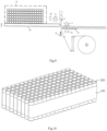
- the reciprocating mechanism may be additionally provided with a conveying belt which is different from the conveying belt 32 in the tidying mechanism 30, but the conveying belts are connected in a front-and-rear mode, as shown in FIG. 3 .
- the specific mounting position and the glue-spraying form of the second glue-spraying component 62 can be flexibly selected by those skilled in the art according to actual conditions.
- glue can be synchronously sprayed to the other side of the bagged spring string; or after the strip-shaped material is completely bonded to a side of a bagged spring string, glue is sprayed by means of the second glue-spraying component 62, for example, the second glue-spraying component 62 can be configured to reciprocate above the conveying belt 32, glue is directly sprayed on a semi-finished bagged spring bed core.
- the reciprocating mechanism pushes the bagged spring string bonded with the strip-shaped material into the support 51, the bagged spring string bonded with the strip-shaped material is bonded to the semi-finished bagged spring bed core, and the operations are repeated to form a complete bagged spring bed core.
- the strip-shaped material is a mesh fabric
- glue-spraying component 62 Since glue can penetrate through the mesh fabric, it is naturally possible to bond the adjacent bagged spring strings, and the glue only needs to be sprayed once.
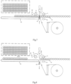
- FIGs. 4-9 schematic diagrams showing that a bagged spring bed core with a side connected to a strip-shaped material is manufactured by the device for manufacturing a bagged spring bed core of the disclosure are illustrated.
- the string feeding impeller 11 of the string feeding mechanism 10 rotates to poke the bagged spring string to move forwards; meanwhile, the bracket 12 moves forwards to stride across the sealing and cutting mechanism 40 and moves to the conveying belt 32, the string feeding mechanism 10 and the feeding mechanism 20 act to respectively convey the bagged spring string and the strip-shaped material to the tidying mechanism 30; moreover, the first glue-spraying component 61 sprays glue on the strip-shaped material, and the strip-shaped material is bonded to the side of the bagged spring string by means of the glue.
- the tidying impeller 31 in the tidying mechanism 30 and the conveying belt 32 act to tidy and adjust the bagged spring string, so that individual springs in the bagged spring string are conveyed in a state of being next to each other; meanwhile, the second glue-spraying component 62 sprays the glue on the other side of the bagged spring string, the bracket 12 moves backwards to reset, the ultrasonic die head 41 and the ultrasonic welding knife 42 move in a closed mode to weld a cloth of the bagged spring string to the strip-shaped material, and the strip-shaped material is cut off by a cutter, so that the bagged spring string connected to the strip-shaped material of a predetermined length is formed. As shown in FIGs.
- the ultrasonic die head 41 and the ultrasonic welding knife 42 open to reset, the tidying impeller 31 and the conveying belt 32 act to convey and move the cut-off bagged spring string connected to the strip-shaped material to the combination mechanism 50, the conveying belt 32 moves upwards to push the bagged spring string connected to the strip-shaped material into the support 51, to be bonded to the bagged spring strings in the support 51, thereby forming the bagged spring bed core.
- the bagged spring bed core with a side connected to a strip-shaped material is formed by arranging and bonding the bagged spring strings connected to the strip-shaped material, the strip-shaped material 100 is bonded to the side of the bagged spring string, and two ends of the strip-shaped material 100 are fixed at the head end and the tail end of the bagged spring string, respectively.
- the width of the strip-shaped material is equal to or smaller than the height of the bagged spring string.
- the strip-shaped material and the bagged spring string are sealed and cut by ultrasonic waves, two ends of the strip-shaped material are also naturally welded to two ends of the bagged spring string, the head end and the tail end of the bagged spring string connected to the strip-shaped material are each provided with three layers of materials, where two layers are cloths of the bagged spring string, and another layer is a strip-shaped material.
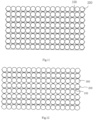
- the bagged spring bed core is formed by staggering and bonding bagged spring strings 200 connected to the strip-shaped material and common bagged spring strings 300.
- the side of the common bagged spring string 300 is not bonded with the strip-shaped material, the amount of glue and strip-shaped material used is reduced, and it is also ensured that the bagged spring bed core has good dimensional stability.
- a sponge strip or a latex strip may also be bonded between adjacent bagged spring strings 200 connected to the strip-shaped material.
- bonding glue points are certainly formed between the adjacent bagged spring strings.
- the bonding glue points are completely disposed in an area of the strip-shaped material.
- the strip-shaped material 100 has a small width, at least one of the bonding glue points is distributed in a cloth area on an upper layer of the bagged spring string, and at least one bonding glue point is distributed in a cloth area on a lower layer of the bagged spring string.
- the strip-shaped material 100 may be selected from a non-woven fabric, a mesh fabric or foamed cotton and the like according to the actual situation.
- bagged spring strings 200 and a strip-shaped material 100 are respectively provided; glue is sprayed at a position where the bagged spring string 200 is in contact with the strip-shaped material 100 so that the strip-shaped material 100 is bonded to the bagged spring string 200, and the bagged spring string connected to the strip-shaped material is sealed and cut by means of ultrasonic waves and cut into a predetermined length.
- the bagged spring strings 200 are bonded to the strip-shaped material 100
- the bagged spring strings 200 are tidied and adjusted and compressed in the length direction, so that individual springs are adjacent to each other.
- the strip-shaped material 100 is stretched to make the strip-shaped material in a tightened state. In this way, after bonding, the bagged spring string is in a more stable state in the length direction and is prevented from being lengthened or shortened by an external force.
Landscapes
- Engineering & Computer Science (AREA)
- Mechanical Engineering (AREA)
- Manufacturing & Machinery (AREA)
- Textile Engineering (AREA)
- Absorbent Articles And Supports Therefor (AREA)
- Wire Processing (AREA)
Claims (16)
- Vorrichtung zum Herstellen eines Taschenfederbettkerns mit streifenförmigem mit einer Seite verbundenem Material, die Folgendes umfasst:einen Bandzufuhrmechanismus (10) zum Befördern eines Taschenfederbands,einen Zufuhrmechanismus (20) zum Befördern von streifenförmigem Material,einen Versäuberungsmechanismus (30) zum Überlagern und Verbinden des Taschenfederbands mit dem streifenförmigen Material, wobei der Versäuberungsmechanismus (30) ein Versäuberungsrad (31) und ein Förderband (32), die in einem Intervall oben und unten vorgesehen sind, und einen Spalt zwischen dem Versäuberungsrad (31) und dem Förderband (32) umfasst, durch den das überlagerte Taschenfederband und das streifenförmige Material verlaufen; undeinen Versiegelungs- und Schneidmechanismus (40) zum Abschneiden des Taschenfederbands und des streifenförmigen Materials, die zwischen dem Bandzufuhrmechanismus (10) und dem Versäuberungsmechanismus (30) angeordnet sind.
- Vorrichtung zum Herstellen eines Taschenfederbettkerns mit streifenförmigem mit einer Seite verbundenem Material nach Anspruch 1, wobei vor dem Überlagern des Taschenfederbands auf dem streifenförmigen Material mittels einer ersten Leimsprühkomponente (61) Leim auf das streifenförmige Material und/oder das Taschenfederband gesprüht wird.
- Vorrichtung zum Herstellen eines Taschenfederbettkerns mit streifenförmigem mit einer Seite verbundenem Material nach Anspruch 1, wobei das Taschenfederband und das streifenförmige Material gemeinsam abgeschnitten und zusammen einer Lotversiegelung durch den Versiegelungs- und Schneidmechanismus (40) unterzogen werden.
- Vorrichtung zum Herstellen eines Taschenfederbettkerns mit streifenförmigem mit einer Seite verbundenem Material nach Anspruch 1, wobei der Versäuberungsmechanismus (30) ferner eine magnetische Saugvorrichtung (33) umfasst, die unten am Förderband (32) angeordnet ist.
- Vorrichtung zum Herstellen eines Taschenfederbettkerns mit streifenförmigem mit einer Seite verbundenem Material nach Anspruch 1, wobei der Bandzufuhrmechanismus (10) ein Bandzufuhrrad (11) und eine hin und hergehende Halterung (12) umfasst, die in einem Intervall oben und unten vorgesehen sind.
- Vorrichtung zum Herstellen eines Taschenfederbettkerns mit streifenförmigem mit einer Seite verbundenem Material nach Anspruch 1, wobei der Versiegelungs- und Schneidmechanismus (40) einen Ultraschallwerkzeugkopf (41), der sich in einem Öffnungsund Schließmodus nach oben und unten bewegt, ein Ultraschallschweißmesser (42) und eine Abschneidkomponente (43) zum Abschneiden des streifenförmigen Materials umfasst; jedes des Ultraschallwerkzeugkopfes (41) und des Ultraschallschweißmessers (42) in einem geschlossenen Kontaktabschnitt entsprechend mit einer Gleitnut (44) versehen ist, und die Abschneidkomponente (43) in der Gleitnut (44) angeordnet ist und sich zurück und vor bewegen kann.
- Vorrichtung zum Herstellen eines Taschenfederbettkerns mit streifenförmigem mit einer Seite verbundenem Material nach Anspruch 6, wobei die Abschneidkomponente (43) eine elektrisch beheizte Schneideinrichtung ist.
- Vorrichtung zum Herstellen eines Taschenfederbettkerns mit streifenförmigem mit einer Seite verbundenem Material nach einem der Ansprüche 1 bis 7, die ferner einen Kombinationsmechanismus (50) zum Kleben und Kombinieren Taschenfederbändern, die mit einem streifenförmigen Material verbunden sind, umfasst, um einen Taschenfederbettkern zu bilden, und bevor der Taschenfederbettkern durch Kleben und Kombinieren gebildet wird, mittels einer zweiten Leimsprühkomponente (62) Leim auf die Taschenfederbänder, die mit dem streifenförmigen Material verbunden sind, gesprüht wird.
- Vorrichtung zum Herstellen eines Taschenfederbettkerns mit streifenförmigem mit einer Seite verbundenem Material nach Anspruch 8, wobei der Kombinationsmechanismus (50) zum Fixieren des Taschenfederbettkerns eine Stütze (51) und zum Schieben des Taschenfederbands, das mit dem streifenförmigen Material verbunden ist, in die Stütze (51) einen hin und hergehenden Mechanismus umfasst.
- Vorrichtung zum Herstellen eines Taschenfederbettkerns mit streifenförmigem mit einer Seite verbundenem Material nach Anspruch 9, wobei der hin und hergehende Mechanismus durch ein Förderband (32) gebildet wird, das nach oben und unten hin und hergehen kann.
- Vorrichtung zum Herstellen eines Taschenfederbettkerns mit streifenförmigem mit einer Seite verbundenem Material nach Anspruch 1, wobei ein Geschwindigkeitsunterschied zwischen dem Versäuberungsrad (31) und dem Förderband (32) einstellbar ist.
- Vorrichtung zum Herstellen eines Taschenfederbettkerns mit streifenförmigem mit einer Seite verbundenem Material nach Anspruch 2, wobei sich gegenüber dem streifenförmigen Material ein Leimauslass der ersten Leimsprühkomponente (61) befindet, um Leim auf das streifenförmige Material zu sprühen.
- Vorrichtung zum Herstellen eines Taschenfederbettkerns mit streifenförmigem mit einer Seite verbundenem Material nach Anspruch 5, wobei die erste Leimsprühkomponente (61) unter der Halterung (12) angeordnet ist; eine Kerbe (13) gebildet ist, die die Halterung (12) durchdringt; und der Leimauslass der ersten Leimsprühkomponente (61) sich gegenüber der Kerbe (13) der Halterung (12) befindet, um durch die Kerbe (13) Leim auf das Taschenfederband zu sprühen.
- Verfahren zum Herstellen eines Taschenfederbettkerns mit streifenförmigem mit einer Seite verbundenem Material, das Folgendes umfasst:Bereitstellen einer Vorrichtung zum Herstellen eines Taschenfederbettkerns gemäß einem der vorhergehenden Ansprüche;Bereitstellen eines Taschenfederbands bzw. eines streifenförmigen Materials;Überlagern und Verbinden des Taschenfederbands mit dem streifenförmigen Material durch den Versäuberungsmechanismus (30) ;Schneiden des Taschenfederbands, das mit dem streifenförmigen Material verbunden ist, in eine vorbestimmte Länge; undBilden eines Taschenfederbettkerns durch Kleben und Kombinieren einer Vielzahl der Taschenfederbänder, von denen jedes Seite an Seite mit dem streifenförmigen Material verbunden ist, oder durch Staffeln und Kleben einer Vielzahl der Taschenfederbänder, von denen jedes mit gemeinsamen Taschenfederbändern mit dem streifenförmigen Material verbunden ist.
- Verfahren zum Herstellen eines Taschenfederbettkerns mit streifenförmigem mit einer Seite verbundenem Material nach Anspruch 14, das Folgendes umfasst: Sprühen von Leim in einer Position, in der das Taschenfederband mit dem streifenförmigen Material in Kontakt ist, um das streifenförmige Material an das Taschenfederband zu kleben; Schneiden des Taschenfederbands, das mit dem streifenförmigen Material verbunden ist, in eine vorbestimmte Länge; und Fixieren von zwei Enden des streifenförmigen Materials an einem vorderen Ende bzw. einem hinteren Ende des Taschenfederbands.
- Verfahren zum Herstellen eines Taschenfederbettkerns mit streifenförmigem mit einer Seite verbundenem Material nach Anspruch 14 oder 15, das ferner Folgendes umfasst: wenn das Taschenfederband an das streifenförmige Material geklebt ist, Anpassen des Taschenfederbands derart, dass einzelne Feder des Taschenfederbands einander benachbart sind, und Strecken des streifenförmigen Materials, um das streifenförmige Material in einen gestrafften Zustand zu versetzen.
Applications Claiming Priority (2)
| Application Number | Priority Date | Filing Date | Title |
|---|---|---|---|
| CN201811021895.1A CN108887997A (zh) | 2018-08-31 | 2018-08-31 | 一种侧面接有带状材料的袋装弹簧床芯及其制造装置、方法 |
| PCT/CN2019/075885 WO2020042547A1 (zh) | 2018-08-31 | 2019-02-22 | 一种侧面接有带状材料的袋装弹簧床芯及其制造装置、方法 |
Publications (4)
| Publication Number | Publication Date |
|---|---|
| EP3821765A1 EP3821765A1 (de) | 2021-05-19 |
| EP3821765A4 EP3821765A4 (de) | 2022-05-25 |
| EP3821765C0 EP3821765C0 (de) | 2024-01-24 |
| EP3821765B1 true EP3821765B1 (de) | 2024-01-24 |
Family
ID=64359243
Family Applications (1)
| Application Number | Title | Priority Date | Filing Date |
|---|---|---|---|
| EP19805108.8A Active EP3821765B1 (de) | 2018-08-31 | 2019-02-22 | Vorrichtung und verfahren zur herstellung einer taschenfederkernmatratze mit an der seitenfläche angebrachtem streifenmaterial |
Country Status (5)
| Country | Link |
|---|---|
| US (1) | US20200198961A1 (de) |
| EP (1) | EP3821765B1 (de) |
| CN (1) | CN108887997A (de) |
| PL (1) | PL3821765T3 (de) |
| WO (1) | WO2020042547A1 (de) |
Families Citing this family (15)
| Publication number | Priority date | Publication date | Assignee | Title |
|---|---|---|---|---|
| WO2018136253A1 (en) * | 2017-01-17 | 2018-07-26 | Wolfson Martin | Automatic assembly of glueless pocketed spring units |
| CN108887997A (zh) * | 2018-08-31 | 2018-11-27 | 广州市联柔机械设备有限公司 | 一种侧面接有带状材料的袋装弹簧床芯及其制造装置、方法 |
| CN110328309A (zh) * | 2019-06-27 | 2019-10-15 | 浙江华剑智能装备有限公司 | 袋装弹簧串输送装置和方法及弹簧芯体生产设备和方法 |
| CN110589079B (zh) * | 2019-08-20 | 2021-04-23 | 广州市联柔机械设备有限公司 | 袋装弹簧柔性封装装置、方法、制造设备及袋装弹簧 |
| WO2021098117A1 (zh) * | 2019-11-18 | 2021-05-27 | 浙江华剑智能装备股份有限公司 | 袋装弹簧芯体生产设备和方法 |
| WO2021098118A1 (zh) * | 2019-11-18 | 2021-05-27 | 浙江华剑智能装备股份有限公司 | 袋装弹簧芯体生产设备和方法 |
| CN114683556A (zh) * | 2020-12-30 | 2022-07-01 | 常熟普逸家居制品有限公司 | 一种袋装弹簧组合机 |
| AU2022272297A1 (en) * | 2021-05-10 | 2023-12-14 | Johnson, Lonnie Carter | Glueless pocketed spring cushioning unit assembler |
| CN113860252B (zh) * | 2021-09-15 | 2022-06-24 | 广州市联柔机械设备有限公司 | 一种袋装弹簧床网制备装置及方法 |
| CN113854775B (zh) * | 2021-09-15 | 2023-07-07 | 广州市联柔机械设备有限公司 | 一种吸附装置及袋装弹簧床网的制备设备 |
| CN113854776B (zh) * | 2021-11-11 | 2024-08-23 | 广州市联柔机械设备有限公司 | 可拆解的袋装弹簧串制造设备 |
| CN114192705B (zh) * | 2021-11-19 | 2024-07-16 | 广东德帆科技有限公司 | 一种床芯弹簧的全自动生产设备 |
| CN114916794B (zh) * | 2022-05-25 | 2023-08-08 | 广州市联柔机械设备有限公司 | 袋装弹簧床芯表面粘贴定型材料的方法、工位布局结构及设备 |
| US12054381B2 (en) * | 2023-01-11 | 2024-08-06 | L&P Property Management Company | Method of manufacturing partially foam encased pocketed spring assembly |
| CN117645268B (zh) * | 2023-10-19 | 2025-11-04 | 广州市联柔机械设备有限公司 | 一种弹簧床网缝合设备及弹簧床网缝合方法 |
Citations (1)
| Publication number | Priority date | Publication date | Assignee | Title |
|---|---|---|---|---|
| EP2653070A1 (de) * | 2012-04-17 | 2013-10-23 | AGRO Holding GmbH | Taschenfederkern |
Family Cites Families (12)
| Publication number | Priority date | Publication date | Assignee | Title |
|---|---|---|---|---|
| DE3728148A1 (de) * | 1987-08-24 | 1989-03-09 | Andreas Breckle | Taschenfederkernmatratze |
| US6295673B1 (en) * | 1998-07-24 | 2001-10-02 | L & P Property Management Company | Reinforced pocketed spring assembly |
| EP0985369A1 (de) * | 1998-09-09 | 2000-03-15 | Matsushita Industrial Co. Ltd. | Federgefüge für Möbel, insbesondere Betten, und Verfahren zu dessen Herstellung |
| US20080110574A1 (en) * | 2006-11-09 | 2008-05-15 | Hiroyuki Etoh | Sealing and cutting device for pocket coil row |
| CN102173373B (zh) * | 2011-03-22 | 2015-04-29 | 广州市联柔机械设备有限公司 | 改进型床网组合机排列弹簧叶轮装置 |
| ITRN20130026A1 (it) * | 2013-06-24 | 2014-12-25 | Flexfor S R L | Struttura per materasso, macchina e metodo di realizzazione di detta struttura per materasso. |
| CN203973196U (zh) * | 2014-07-22 | 2014-12-03 | 绍兴市华剑床垫机械有限公司 | 一种袋装弹簧条切断机构 |
| CN204224906U (zh) * | 2014-10-30 | 2015-03-25 | 广州市联柔机械设备有限公司 | 一种袋装弹簧装袋封切装置 |
| CN105292582B (zh) * | 2015-10-19 | 2016-10-26 | 绍兴市华建床垫机械有限公司 | 一种用于传输袋装弹簧串的装置 |
| CN105947968A (zh) * | 2016-05-04 | 2016-09-21 | 广州市联柔机械设备有限公司 | 一种多通道袋装弹簧串输送机构及袋装弹簧垫制造装置 |
| CN207470550U (zh) * | 2017-10-23 | 2018-06-08 | 绍兴市华剑床垫机械有限公司 | 袋装弹簧串粘胶机 |
| CN108887997A (zh) * | 2018-08-31 | 2018-11-27 | 广州市联柔机械设备有限公司 | 一种侧面接有带状材料的袋装弹簧床芯及其制造装置、方法 |
-
2018
- 2018-08-31 CN CN201811021895.1A patent/CN108887997A/zh active Pending
-
2019
- 2019-02-22 WO PCT/CN2019/075885 patent/WO2020042547A1/zh not_active Ceased
- 2019-02-22 US US16/625,994 patent/US20200198961A1/en not_active Abandoned
- 2019-02-22 PL PL19805108.8T patent/PL3821765T3/pl unknown
- 2019-02-22 EP EP19805108.8A patent/EP3821765B1/de active Active
Patent Citations (1)
| Publication number | Priority date | Publication date | Assignee | Title |
|---|---|---|---|---|
| EP2653070A1 (de) * | 2012-04-17 | 2013-10-23 | AGRO Holding GmbH | Taschenfederkern |
Also Published As
| Publication number | Publication date |
|---|---|
| PL3821765T3 (pl) | 2024-04-29 |
| CN108887997A (zh) | 2018-11-27 |
| EP3821765C0 (de) | 2024-01-24 |
| US20200198961A1 (en) | 2020-06-25 |
| EP3821765A1 (de) | 2021-05-19 |
| WO2020042547A1 (zh) | 2020-03-05 |
| EP3821765A4 (de) | 2022-05-25 |
Similar Documents
| Publication | Publication Date | Title |
|---|---|---|
| EP3821765B1 (de) | Vorrichtung und verfahren zur herstellung einer taschenfederkernmatratze mit an der seitenfläche angebrachtem streifenmaterial | |
| US6347423B1 (en) | Jacketed cushioning elements and assemblies thereof in mattresses and upholstery | |
| US4854023A (en) | Method for providing pocketed coil strings having a flat overlap side seam | |
| US4986518A (en) | Pocketed coil strings having a flat overlap side seam | |
| JP2933203B2 (ja) | ポケットコイルバネ構造体組み立て装置 | |
| US9370252B2 (en) | Pocketed spring assembly | |
| US5126004A (en) | Method and apparatus for assembling innerspring construction for mattresses, cushions and the like | |
| US6591436B2 (en) | Side seam pocketed coil springs | |
| US10722044B2 (en) | Dual-layered fabric for use in pocketed spring assembly | |
| JP4874373B2 (ja) | ポケットコイルバネ構造体組立装置 | |
| KR100977946B1 (ko) | 포켓스프링 공급장치 | |
| US6374442B1 (en) | Pocketed coil spring unit with combination of top and bottom sheets and inter-row bonding | |
| CN110589079B (zh) | 袋装弹簧柔性封装装置、方法、制造设备及袋装弹簧 | |
| KR102048824B1 (ko) | 침대 매트리스의 스프링 홀더 및 제조 방법 | |
| CN110885058A (zh) | 袋装弹簧芯体生产设备和方法 | |
| US20080110574A1 (en) | Sealing and cutting device for pocket coil row | |
| CN107053733B (zh) | 弹簧整定装置、用于形成袋装弹簧串的设备和整定弹簧的方法 | |
| CN208962504U (zh) | 无胶袋装弹簧芯体的生产设备 | |
| CN211310824U (zh) | 袋装弹簧串生产设备 | |
| CN111053395B (zh) | 袋装弹簧芯体生产设备和生产方法 | |
| CN208962503U (zh) | 无胶袋装弹簧芯体的生产设备 | |
| CN217944386U (zh) | 一种拉带成型机 | |
| CN211310823U (zh) | 袋装弹簧芯体生产设备 | |
| CN217565470U (zh) | 弹簧床芯制造设备和弹簧床芯 | |
| CN211310822U (zh) | 袋装弹簧芯体生产设备 |
Legal Events
| Date | Code | Title | Description |
|---|---|---|---|
| STAA | Information on the status of an ep patent application or granted ep patent |
Free format text: STATUS: UNKNOWN |
|
| STAA | Information on the status of an ep patent application or granted ep patent |
Free format text: STATUS: THE INTERNATIONAL PUBLICATION HAS BEEN MADE |
|
| PUAI | Public reference made under article 153(3) epc to a published international application that has entered the european phase |
Free format text: ORIGINAL CODE: 0009012 |
|
| STAA | Information on the status of an ep patent application or granted ep patent |
Free format text: STATUS: REQUEST FOR EXAMINATION WAS MADE |
|
| 17P | Request for examination filed |
Effective date: 20191126 |
|
| AK | Designated contracting states |
Kind code of ref document: A1 Designated state(s): AL AT BE BG CH CY CZ DE DK EE ES FI FR GB GR HR HU IE IS IT LI LT LU LV MC MK MT NL NO PL PT RO RS SE SI SK SM TR |
|
| DAV | Request for validation of the european patent (deleted) | ||
| DAX | Request for extension of the european patent (deleted) | ||
| A4 | Supplementary search report drawn up and despatched |
Effective date: 20220425 |
|
| RIC1 | Information provided on ipc code assigned before grant |
Ipc: B68G 15/00 20060101ALI20220419BHEP Ipc: A47C 27/06 20060101AFI20220419BHEP |
|
| RIC1 | Information provided on ipc code assigned before grant |
Ipc: B68G 15/00 20060101ALI20230907BHEP Ipc: A47C 27/06 20060101AFI20230907BHEP |
|
| GRAP | Despatch of communication of intention to grant a patent |
Free format text: ORIGINAL CODE: EPIDOSNIGR1 |
|
| STAA | Information on the status of an ep patent application or granted ep patent |
Free format text: STATUS: GRANT OF PATENT IS INTENDED |
|
| INTG | Intention to grant announced |
Effective date: 20231025 |
|
| GRAS | Grant fee paid |
Free format text: ORIGINAL CODE: EPIDOSNIGR3 |
|
| GRAA | (expected) grant |
Free format text: ORIGINAL CODE: 0009210 |
|
| STAA | Information on the status of an ep patent application or granted ep patent |
Free format text: STATUS: THE PATENT HAS BEEN GRANTED |
|
| AK | Designated contracting states |
Kind code of ref document: B1 Designated state(s): AL AT BE BG CH CY CZ DE DK EE ES FI FR GB GR HR HU IE IS IT LI LT LU LV MC MK MT NL NO PL PT RO RS SE SI SK SM TR |
|
| REG | Reference to a national code |
Ref country code: GB Ref legal event code: FG4D |
|
| REG | Reference to a national code |
Ref country code: CH Ref legal event code: EP |
|
| REG | Reference to a national code |
Ref country code: DE Ref legal event code: R096 Ref document number: 602019045684 Country of ref document: DE |
|
| REG | Reference to a national code |
Ref country code: IE Ref legal event code: FG4D |
|
| U01 | Request for unitary effect filed |
Effective date: 20240212 |
|
| U07 | Unitary effect registered |
Designated state(s): AT BE BG DE DK EE FI FR IT LT LU LV MT NL PT SE SI Effective date: 20240221 |
|
| U20 | Renewal fee for the european patent with unitary effect paid |
Year of fee payment: 6 Effective date: 20240221 |
|
| PG25 | Lapsed in a contracting state [announced via postgrant information from national office to epo] |
Ref country code: IS Free format text: LAPSE BECAUSE OF FAILURE TO SUBMIT A TRANSLATION OF THE DESCRIPTION OR TO PAY THE FEE WITHIN THE PRESCRIBED TIME-LIMIT Effective date: 20240524 |
|
| PG25 | Lapsed in a contracting state [announced via postgrant information from national office to epo] |
Ref country code: GR Free format text: LAPSE BECAUSE OF FAILURE TO SUBMIT A TRANSLATION OF THE DESCRIPTION OR TO PAY THE FEE WITHIN THE PRESCRIBED TIME-LIMIT Effective date: 20240425 |
|
| PG25 | Lapsed in a contracting state [announced via postgrant information from national office to epo] |
Ref country code: HR Free format text: LAPSE BECAUSE OF FAILURE TO SUBMIT A TRANSLATION OF THE DESCRIPTION OR TO PAY THE FEE WITHIN THE PRESCRIBED TIME-LIMIT Effective date: 20240124 Ref country code: RS Free format text: LAPSE BECAUSE OF FAILURE TO SUBMIT A TRANSLATION OF THE DESCRIPTION OR TO PAY THE FEE WITHIN THE PRESCRIBED TIME-LIMIT Effective date: 20240424 |
|
| PG25 | Lapsed in a contracting state [announced via postgrant information from national office to epo] |
Ref country code: ES Free format text: LAPSE BECAUSE OF FAILURE TO SUBMIT A TRANSLATION OF THE DESCRIPTION OR TO PAY THE FEE WITHIN THE PRESCRIBED TIME-LIMIT Effective date: 20240124 |
|
| PG25 | Lapsed in a contracting state [announced via postgrant information from national office to epo] |
Ref country code: RS Free format text: LAPSE BECAUSE OF FAILURE TO SUBMIT A TRANSLATION OF THE DESCRIPTION OR TO PAY THE FEE WITHIN THE PRESCRIBED TIME-LIMIT Effective date: 20240424 Ref country code: NO Free format text: LAPSE BECAUSE OF FAILURE TO SUBMIT A TRANSLATION OF THE DESCRIPTION OR TO PAY THE FEE WITHIN THE PRESCRIBED TIME-LIMIT Effective date: 20240424 Ref country code: IS Free format text: LAPSE BECAUSE OF FAILURE TO SUBMIT A TRANSLATION OF THE DESCRIPTION OR TO PAY THE FEE WITHIN THE PRESCRIBED TIME-LIMIT Effective date: 20240524 Ref country code: HR Free format text: LAPSE BECAUSE OF FAILURE TO SUBMIT A TRANSLATION OF THE DESCRIPTION OR TO PAY THE FEE WITHIN THE PRESCRIBED TIME-LIMIT Effective date: 20240124 Ref country code: GR Free format text: LAPSE BECAUSE OF FAILURE TO SUBMIT A TRANSLATION OF THE DESCRIPTION OR TO PAY THE FEE WITHIN THE PRESCRIBED TIME-LIMIT Effective date: 20240425 Ref country code: ES Free format text: LAPSE BECAUSE OF FAILURE TO SUBMIT A TRANSLATION OF THE DESCRIPTION OR TO PAY THE FEE WITHIN THE PRESCRIBED TIME-LIMIT Effective date: 20240124 |
|
| REG | Reference to a national code |
Ref country code: CH Ref legal event code: PL |
|
| PG25 | Lapsed in a contracting state [announced via postgrant information from national office to epo] |
Ref country code: SM Free format text: LAPSE BECAUSE OF FAILURE TO SUBMIT A TRANSLATION OF THE DESCRIPTION OR TO PAY THE FEE WITHIN THE PRESCRIBED TIME-LIMIT Effective date: 20240124 |
|
| PG25 | Lapsed in a contracting state [announced via postgrant information from national office to epo] |
Ref country code: CH Free format text: LAPSE BECAUSE OF NON-PAYMENT OF DUE FEES Effective date: 20240229 |
|
| PG25 | Lapsed in a contracting state [announced via postgrant information from national office to epo] |
Ref country code: CZ Free format text: LAPSE BECAUSE OF FAILURE TO SUBMIT A TRANSLATION OF THE DESCRIPTION OR TO PAY THE FEE WITHIN THE PRESCRIBED TIME-LIMIT Effective date: 20240124 |
|
| REG | Reference to a national code |
Ref country code: DE Ref legal event code: R097 Ref document number: 602019045684 Country of ref document: DE |
|
| PG25 | Lapsed in a contracting state [announced via postgrant information from national office to epo] |
Ref country code: SK Free format text: LAPSE BECAUSE OF FAILURE TO SUBMIT A TRANSLATION OF THE DESCRIPTION OR TO PAY THE FEE WITHIN THE PRESCRIBED TIME-LIMIT Effective date: 20240124 |
|
| PG25 | Lapsed in a contracting state [announced via postgrant information from national office to epo] |
Ref country code: SM Free format text: LAPSE BECAUSE OF FAILURE TO SUBMIT A TRANSLATION OF THE DESCRIPTION OR TO PAY THE FEE WITHIN THE PRESCRIBED TIME-LIMIT Effective date: 20240124 Ref country code: SK Free format text: LAPSE BECAUSE OF FAILURE TO SUBMIT A TRANSLATION OF THE DESCRIPTION OR TO PAY THE FEE WITHIN THE PRESCRIBED TIME-LIMIT Effective date: 20240124 Ref country code: CZ Free format text: LAPSE BECAUSE OF FAILURE TO SUBMIT A TRANSLATION OF THE DESCRIPTION OR TO PAY THE FEE WITHIN THE PRESCRIBED TIME-LIMIT Effective date: 20240124 Ref country code: CH Free format text: LAPSE BECAUSE OF NON-PAYMENT OF DUE FEES Effective date: 20240229 |
|
| PG25 | Lapsed in a contracting state [announced via postgrant information from national office to epo] |
Ref country code: MC Free format text: LAPSE BECAUSE OF FAILURE TO SUBMIT A TRANSLATION OF THE DESCRIPTION OR TO PAY THE FEE WITHIN THE PRESCRIBED TIME-LIMIT Effective date: 20240124 |
|
| PG25 | Lapsed in a contracting state [announced via postgrant information from national office to epo] |
Ref country code: MC Free format text: LAPSE BECAUSE OF FAILURE TO SUBMIT A TRANSLATION OF THE DESCRIPTION OR TO PAY THE FEE WITHIN THE PRESCRIBED TIME-LIMIT Effective date: 20240124 |
|
| PLBE | No opposition filed within time limit |
Free format text: ORIGINAL CODE: 0009261 |
|
| STAA | Information on the status of an ep patent application or granted ep patent |
Free format text: STATUS: NO OPPOSITION FILED WITHIN TIME LIMIT |
|
| GBPC | Gb: european patent ceased through non-payment of renewal fee |
Effective date: 20240424 |
|
| 26N | No opposition filed |
Effective date: 20241025 |
|
| PG25 | Lapsed in a contracting state [announced via postgrant information from national office to epo] |
Ref country code: GB Free format text: LAPSE BECAUSE OF NON-PAYMENT OF DUE FEES Effective date: 20240424 |
|
| PG25 | Lapsed in a contracting state [announced via postgrant information from national office to epo] |
Ref country code: IE Free format text: LAPSE BECAUSE OF NON-PAYMENT OF DUE FEES Effective date: 20240222 |
|
| PG25 | Lapsed in a contracting state [announced via postgrant information from national office to epo] |
Ref country code: IE Free format text: LAPSE BECAUSE OF NON-PAYMENT OF DUE FEES Effective date: 20240222 Ref country code: GB Free format text: LAPSE BECAUSE OF NON-PAYMENT OF DUE FEES Effective date: 20240424 |
|
| U20 | Renewal fee for the european patent with unitary effect paid |
Year of fee payment: 7 Effective date: 20250107 |
|
| PG25 | Lapsed in a contracting state [announced via postgrant information from national office to epo] |
Ref country code: RO Free format text: LAPSE BECAUSE OF FAILURE TO SUBMIT A TRANSLATION OF THE DESCRIPTION OR TO PAY THE FEE WITHIN THE PRESCRIBED TIME-LIMIT Effective date: 20240124 |
|
| PG25 | Lapsed in a contracting state [announced via postgrant information from national office to epo] |
Ref country code: CY Free format text: LAPSE BECAUSE OF FAILURE TO SUBMIT A TRANSLATION OF THE DESCRIPTION OR TO PAY THE FEE WITHIN THE PRESCRIBED TIME-LIMIT; INVALID AB INITIO Effective date: 20190222 |
|
| PG25 | Lapsed in a contracting state [announced via postgrant information from national office to epo] |
Ref country code: HU Free format text: LAPSE BECAUSE OF FAILURE TO SUBMIT A TRANSLATION OF THE DESCRIPTION OR TO PAY THE FEE WITHIN THE PRESCRIBED TIME-LIMIT; INVALID AB INITIO Effective date: 20190222 |
|
| PG25 | Lapsed in a contracting state [announced via postgrant information from national office to epo] |
Ref country code: TR Free format text: LAPSE BECAUSE OF FAILURE TO SUBMIT A TRANSLATION OF THE DESCRIPTION OR TO PAY THE FEE WITHIN THE PRESCRIBED TIME-LIMIT Effective date: 20240124 |
|
| PGFP | Annual fee paid to national office [announced via postgrant information from national office to epo] |
Ref country code: PL Payment date: 20251230 Year of fee payment: 8 |
|
| U20 | Renewal fee for the european patent with unitary effect paid |
Year of fee payment: 8 Effective date: 20260106 |