EP3821142B1 - Verbindungsbolzen zur werkzeuglosen stossverbindung zweier möbelplatten - Google Patents
Verbindungsbolzen zur werkzeuglosen stossverbindung zweier möbelplatten Download PDFInfo
- Publication number
- EP3821142B1 EP3821142B1 EP19794134.7A EP19794134A EP3821142B1 EP 3821142 B1 EP3821142 B1 EP 3821142B1 EP 19794134 A EP19794134 A EP 19794134A EP 3821142 B1 EP3821142 B1 EP 3821142B1
- Authority
- EP
- European Patent Office
- Prior art keywords
- bolt
- bore
- projection
- connection bolt
- head
- Prior art date
- Legal status (The legal status is an assumption and is not a legal conclusion. Google has not performed a legal analysis and makes no representation as to the accuracy of the status listed.)
- Active
Links
Images

Classifications
-
- F—MECHANICAL ENGINEERING; LIGHTING; HEATING; WEAPONS; BLASTING
- F16—ENGINEERING ELEMENTS AND UNITS; GENERAL MEASURES FOR PRODUCING AND MAINTAINING EFFECTIVE FUNCTIONING OF MACHINES OR INSTALLATIONS; THERMAL INSULATION IN GENERAL
- F16B—DEVICES FOR FASTENING OR SECURING CONSTRUCTIONAL ELEMENTS OR MACHINE PARTS TOGETHER, e.g. NAILS, BOLTS, CIRCLIPS, CLAMPS, CLIPS OR WEDGES; JOINTS OR JOINTING
- F16B12/00—Jointing of furniture or the like, e.g. hidden from exterior
- F16B12/10—Jointing of furniture or the like, e.g. hidden from exterior using pegs, bolts, tenons, clamps, clips, or the like
- F16B12/12—Jointing of furniture or the like, e.g. hidden from exterior using pegs, bolts, tenons, clamps, clips, or the like for non-metal furniture parts, e.g. made of wood, of plastics
- F16B12/24—Jointing of furniture or the like, e.g. hidden from exterior using pegs, bolts, tenons, clamps, clips, or the like for non-metal furniture parts, e.g. made of wood, of plastics using separate pins, dowels, or the like
-
- F—MECHANICAL ENGINEERING; LIGHTING; HEATING; WEAPONS; BLASTING
- F16—ENGINEERING ELEMENTS AND UNITS; GENERAL MEASURES FOR PRODUCING AND MAINTAINING EFFECTIVE FUNCTIONING OF MACHINES OR INSTALLATIONS; THERMAL INSULATION IN GENERAL
- F16B—DEVICES FOR FASTENING OR SECURING CONSTRUCTIONAL ELEMENTS OR MACHINE PARTS TOGETHER, e.g. NAILS, BOLTS, CIRCLIPS, CLAMPS, CLIPS OR WEDGES; JOINTS OR JOINTING
- F16B12/00—Jointing of furniture or the like, e.g. hidden from exterior
- F16B12/44—Leg joints; Corner joints
- F16B12/46—Non-metal corner connections
-
- F—MECHANICAL ENGINEERING; LIGHTING; HEATING; WEAPONS; BLASTING
- F16—ENGINEERING ELEMENTS AND UNITS; GENERAL MEASURES FOR PRODUCING AND MAINTAINING EFFECTIVE FUNCTIONING OF MACHINES OR INSTALLATIONS; THERMAL INSULATION IN GENERAL
- F16B—DEVICES FOR FASTENING OR SECURING CONSTRUCTIONAL ELEMENTS OR MACHINE PARTS TOGETHER, e.g. NAILS, BOLTS, CIRCLIPS, CLAMPS, CLIPS OR WEDGES; JOINTS OR JOINTING
- F16B19/00—Bolts without screw-thread; Pins, including deformable elements; Rivets
- F16B19/02—Bolts or sleeves for positioning of machine parts, e.g. notched taper pins, fitting pins, sleeves, eccentric positioning rings
-
- F—MECHANICAL ENGINEERING; LIGHTING; HEATING; WEAPONS; BLASTING
- F16—ENGINEERING ELEMENTS AND UNITS; GENERAL MEASURES FOR PRODUCING AND MAINTAINING EFFECTIVE FUNCTIONING OF MACHINES OR INSTALLATIONS; THERMAL INSULATION IN GENERAL
- F16B—DEVICES FOR FASTENING OR SECURING CONSTRUCTIONAL ELEMENTS OR MACHINE PARTS TOGETHER, e.g. NAILS, BOLTS, CIRCLIPS, CLAMPS, CLIPS OR WEDGES; JOINTS OR JOINTING
- F16B5/00—Joining sheets or plates, e.g. panels, to one another or to strips or bars parallel to them
- F16B5/0004—Joining sheets, plates or panels in abutting relationship
- F16B5/008—Joining sheets, plates or panels in abutting relationship by a rotating or sliding and rotating movement
Definitions
- the invention relates to a connecting bolt ("connecting fitting") for connecting two parts, in particular two furniture panels, according to the preamble of claim 1.
- the connecting bolt is particularly suitable for parts made of chipboard, MDF or wood-like materials.
- Such a connecting bolt is shown, for example, by FIG. 8 of the DE 203 07 834 U1 known.
- DE 25 57 966 A1 discloses a floor support with a support body and an inclined, cylindrical retaining pin provided on the periphery of the support body.
- the retaining pin has a conical foot section and a conical head section with a radially outwardly protruding, blade-shaped projection.
- DE 40 17 515 A1 discloses a hanger bolt with a threaded section and with a pin offset parallel to the threaded section.
- DE 295 07 834 U1 finally discloses a connecting bolt for connecting two parts with a cylindrical bolt shank for anchoring in a bore of one part and with a bolt head for anchoring in a bore of the other part.
- the bolt head has a foot section adjoining the bolt shank and a hook-shaped head section with a radial one outwardly protruding, blade-shaped projection, wherein a rear side of the head section opposite the projection has an inclined surface running obliquely with respect to the bolt shank or is designed as a half-cone.
- the present invention is based on the object of developing a connecting bolt of the type mentioned at the outset in such a way that a joint-free and gap-free connection can be achieved between two parts to be connected.
- the connection should also be improved in terms of stability, dimensional stability, aesthetic value of the appearance, etc.
- the axial offset of the bolt head relative to the bolt shank causes a function-determining displacement of the axis of rotation during the pivoting movement of the first part, whereby the axis of rotation, which is defined by the support edge of the inclined first part, is located directly on the edge of the bore of the second part.
- the foot section viewed in the radial direction in which the projection protrudes outwards, has a width which is greater than the shaft diameter. That at the transition The end face of the foot section that is present on the bolt shank represents a depth stop for the first part. In the case of a circular cylindrical foot section, the diameter of the foot section is greater than the shank diameter.
- the projection and the front side of the head section facing the projection are preferably connected to one another by a web or a ramp in order to additionally support the projection and to secure it against plastic deformation.
- the web can particularly advantageously have a concave outer contour which, during the pivoting movement, leads to material compression in the second part and pulls the bolt head further into the bore of the second part.
- the jacket side of the bolt shank can have a barb-like clamping structure, in particular in the form of clamping lugs or grooves.
- the clamping grooves, grooved like barbs prevent the bolt shank from being pulled out of the hole in the first part and are attached in such a way that they grip along the parts (no risk of cracks).
- the invention also relates to an arrangement with two parts which are connected to one another without tools by means of the connecting bolt according to the invention, the bolt shank of the connecting bolt being anchored in a bore of the one, first part and the bolt head being pivoted into a bore of the other, second part and with its projection engages in the bore wall of the second part.
- the second part is made of such a material that the projection can penetrate into the material, preferably made of wood or wood-like material (chipboard, MDF materials).
- the two parts can be, for example, two panels, in particular furniture panels or panel material from furniture components, which are fastened to one another at right angles.
- the bolt shank is firmly seated in the first plate by knocking it in or screwing it into the hole in the face of the first plate.
- the projection of the bolt head digs into the bore wall, whereby the bolt head is also anchored in the bore of the second plate.
- the axis of rotation when swiveling in is defined by the edge of the first plate with which the first plate, which is attached at an angle, rests against the second plate.
- the axial offset is chosen so that the radially forward edge of the bolt head is offset inwardly in relation to the support edge of the diagonally attached first plate and this support edge thus covers the edge of the hole in the end position.
- the connecting bolt (“connector”) 1 shown is used to connect two furniture panels and is made in one piece from metal or plastic.
- the connecting fitting 1 comprises a circular cylindrical bolt shank 2 and a bolt head 3.
- the bolt head 3 has a foot section 4 adjoining the bolt shank 2 and a hook-shaped head section 5 with a radially outwardly protruding, blade-shaped projection 6 .
- the foot section 4 is arranged eccentrically offset in the radial direction 7, in which the projection 6 protrudes radially outwards, relative to the bolt shank 2, that is, the axis 8 of the foot section 4 has an axial offset 9 relative to the shank axis 10 in this direction 7.
- the width B of the foot section 4 or, in the case of a circular cylindrical foot section 4 its diameter D is greater than the shank diameter d, as a result of which the foot section 4 has a sickle-shaped end face 11 at its transition to the bolt shank 2.
- the rear side 5b of the head section 5, which is opposite the projection 6, is designed as an inclined surface 12 which runs obliquely with respect to the shaft axis 10. Alternatively, this rear side 5b can also be designed as a half-cone that tapers in the direction of the free head end.
- the projection 6 and the front 5a of the head section 5 facing the projection 6 are additionally connected to one another by a web (ramp) 13 with a concave outer contour, whereby the projection 6 is additionally supported and protected against plastic deformation.
- the bolt shank 2 On the jacket side, the bolt shank 2 has a barb-like clamping structure that is effective in the direction of the bolt head 3 in the form of alternately several clamping noses or recesses 14a, 14b extending axially and in the circumferential direction, at least the clamping noses 14a extending in the circumferential direction over the jacket surface of the Protruding bolt shank 2.
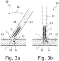
- Figs. 3a, 3b show a furniture arrangement 20 with two plates 21, 22 and the connecting bolt 1.
- the bolt shank 2 is driven in, screwed in or Gluing anchored in a frontal bore 23 of the first plate 21, the first plate 21 resting against the end face 11 of the foot section 4.
- the bolt head 3 is inserted into a bore 24 on the plate side of the second plate 22 by inclining the first plate 21 until the plate edge 25 of the first plate 21 rests on the second plate 22.
- the diameter of the cylindrical foot section 4 ideally corresponds to the diameter of the bore 24.
- the first plate 21 represents a lever extension so that the projection 6 is pressed into the wall of the bore with a correspondingly high force.
- the axis of rotation when swiveling in is defined by the plate edge 25 resting on the second plate 22, which is located directly on the edge of the hole in the second plate 22 due to the axial offset 9.
- the axial offset 9 corresponds to the wall thickness 27 of the first plate 21 remaining between the frontal bore 23 and the outer side of the plate, so that there is neither a joint between the two plates 21, 22 nor a gap between the bolt head 3 and the wall of the bore 24.
- the two plates 21, 22 are now connected to one another at right angles. The connection is only stable when the perpendicularity of the two plates 21, 22 is fixed in the overall assembly.
- the web 13 prevents the projection 9 from bending up and, due to its concave outer contour, compresses the material engaged behind, which causes springback and gives tension and pressure to the connection.
- the suspension compensates for the movement tolerances in contrast to a screw.
Landscapes
- Engineering & Computer Science (AREA)
- General Engineering & Computer Science (AREA)
- Mechanical Engineering (AREA)
- Furniture Connections (AREA)
- Connection Of Plates (AREA)
Description
- Die Erfindung betrifft einen Verbindungsbolzen ("Verbindungsbeschlag") zur Verbindung zweier Teile, insbesondere zweier Möbelplatten, gemäß dem Oberbegriff von Anspruch 1. Der Verbindungsbolzen eignet sich insbesondere für Teile aus Span-, MDF- oder holzähnlichen Materialien.
- Ein derartiger Verbindungsbolzen ist beispielsweise durch die Fig. 8 des
DE 203 07 834 U1 bekannt geworden. -
DE 10 2014 009257 A1 offenbart ein Exzenterelement mit einem Gewindeabschnitt und einem gegenüber der Gewindeachse exzentrisch am Gewindeabschnitt angeordneten Zapfen. -
DE 25 57 966 A1 offenbart einen Bodenträger mit einem Tragkörper und einem am Tragkörper umfangsseitig vorgesehenen, schräggestellten, zylindrischen Haltezapfen. Der Haltezapfen weist einen konischen Fußabschnitt und einen konischen Kopfabschnitt mit einem radial nach außen vorstehenden, schneidenförmigen Vorsprung auf. -
DE 40 17 515 A1 offenbart eine Stockschraube mit einem Gewindeabschnitt und mit einem gegenüber dem Gewindeabschnitt parallelversetzten Zapfen. -
DE 295 07 834 U1 offenbart schließlich einen Verbindungsbolzen zur Verbindung zweier Teile mit einem zylindrischen Bolzenschaft zur Verankerung in einer Bohrung des einen Teils und mit einem Bolzenkopf zur Verankerung in einer Bohrung des anderen Teils. Der Bolzenkopf weist einen sich an den Bolzenschaft anschließenden Fußabschnitt und einen hakenförmigen Kopfabschnitt mit einem radial nach außen vorstehenden, schneidenförmigen Vorsprung auf, wobei eine dem Vorsprung gegenüberliegende Rückseite des Kopfabschnitts eine bezüglich dem Bolzenschaft schräg verlaufende Schrägfläche aufweist oder als Halbkonus ausgebildet ist. - Problematisch bei solchen Stoßverbindungen ist allerdings, dass es zu einer Fugenbildung zwischen den zu verbindenden Teilen kommen kann, sowie ein Spalt zwischen dem auf Stoß verbundenen Teil und der Bohrungswandung ("unsaubere Lochabdeckung") verbleiben kann. Ursächlich hierbei ist, dass sich die Drehachse der Einschwenkbewegung unmittelbar am Bohrungsrand befinden muss und dies bei bekannten Anwendungen über eine ausgeklinkte Abschrägung der Stoßfläche des ersten Teils in diesem Bereich realisiert wird, damit dieses sich schräg ansetzen lässt. Das Kaschieren der Fuge sowie die Abdeckung der sichtbaren Bohrung erfolgen dann nachträglich durch Anziehen eines Gewindes (
DE 295 07 834 U1 ), Überschieben einer Hülse (DE 203 00 574 U1 ) oder ähnliche Hilfsmittel. - Der vorliegenden Erfindung liegt die Aufgabe zugrunde, einen Verbindungsbolzen der eingangs genannten Art dahingehend weiterzubilden, dass eine fugen- und spaltfreie Verbindung zwischen zwei zu verbindenden Teilen erreicht werden kann. Auch soll die Verbindung hinsichtlich Stabilität, Formstabilität, ästhetische Wertigkeit des Erscheinungsbildes, etc. verbessert werden.
- Diese Aufgabe wird erfindungsgemäß durch einen Verbindungsbolzen mit den Merkmalen von Anspruch 1 gelöst.
- Erfindungsgemäß bewirkt der Achsversatz des Bolzenkopfes gegenüber dem Bolzenschaft eine funktionsbestimmende Verlagerung der Drehachse bei der Einschwenkbewegung des ersten Teils, wodurch sich die Drehachse, die durch die Auflagekante des schräg angesetzten ersten Teils definiert ist, unmittelbar am Bohrungsrand des zweiten Teils befindet.
- In einer vorteilhaften Ausführungsform der Erfindung weist der Fußabschnitt, gesehen in der radialen Richtung, in welcher der Vorsprung nach außen vorsteht, eine Breite auf, die größer als der Schaftdurchmesser ist. Die dadurch am Übergang zum Bolzenschaft vorhandene Stirnfläche des Fußabschnitts stellt einen Tiefenanschlag für das erste Teil dar. Im Falle eines kreiszylindrischen Fußabschnitts ist der Durchmesser des Fußabschnitts größer als der Schaftdurchmesser.
- Bevorzugt sind der Vorsprung und die dem Vorsprung zugewandte Vorderseite des Kopfabschnitts durch einen Steg oder eine Rampe miteinander verbunden, um den Vorsprung zusätzlich abzustützen und gegen plastische Verformung zu sichern. Dabei kann der Steg besonders vorteilhaft eine konkave Außenkontur aufweisen, die bei der Einschwenkbewegung zu einer Materialverdichtung im zweiten Teil führt und den Bolzenkopf weiter die Bohrung des zweiten Teils hineinzieht.
- Für eine sichere Verankerung in der Bohrung des ersten Teils kann der Bolzenschaft mantelseitig eine widerhakenartige Klemmstruktur, insbesondere in Form von Klemmnasen oder -rillen, aufweisen. Die wie Widerhaken gerillten Klemmrillen verhindern das Herausziehen des Bolzenschafts aus der Bohrung des ersten Teils und sind so angebracht, dass sie längs der Teile greifen (keine Spaltgefahr).
- Die Erfindung betrifft auch eine Anordnung mit zwei Teilen, die mittels des erfindungsgemäßen Verbindungsbolzens werkzeuglos miteinander verbunden sind, wobei der Bolzenschaft des Verbindungsbolzens in einer Bohrung des einen, ersten Teils verankert ist und der Bolzenkopf in eine Bohrung des anderen, zweiten Teils eingeschwenkt ist und mit seinem Vorsprung in die Bohrungswandung des zweiten Teils eingreift. Das zweite Teil ist aus solch einem Material gebildet, dass der Vorsprung in das Material eindringen kann, vorzugsweise aus Holzwerkstoff oder holzähnlichem Material (Span-, MDF-Materialien). Bei den beiden Teilen kann es sich beispielsweise um zwei Platten, insbesondere Möbelplatten oder Plattenmaterial von Möbelbestandteilen, handeln, die rechtwinklig aneinander befestigt sind.
- Der Bolzenschaft hat durch Einschlagen oder Eindrehen in die stirnseitige Bohrung der ersten Platte einen festen Sitz in der ersten Platte. Durch schräges Einstellen des Bolzenkopfes in die Bohrung der zweiten Platte und anschließendes Einschwenken des Bolzenkopfes gräbt sich der Vorsprung des Bolzenkopfes in die Bohrungswandung ein, wodurch der Bolzenkopf auch in der Bohrung der zweiten Platte verankert ist. Die Drehachse beim Einschwenken wird durch die Kante der ersten Platte, mit der die schräg angesetzte erste Platte an der zweiten Platte anliegt, definiert. Der Achsversatz ist dabei möglichst so gewählt, dass die radial vorgesetzte Kante des Bolzenkopfes gegenüber der Auflagekante der schräg angesetzten ersten Platte nach innen versetzt ist und diese Auflagekante somit in der Endposition den Bohrungsrand überdeckt.
- Weitere Vorteile der Erfindung ergeben sich aus der Beschreibung, den Ansprüchen und der Zeichnung. Ebenso können die vorstehenden genannten und die noch weiter aufgeführten Merkmale je für sich oder zu mehreren in beliebigen Kombinationen Verwendung finden. Die gezeigten und beschriebenen Ausführungsformen sind nicht als abschließende Aufzählung zu verstehen, sondern haben vielmehr beispielhaften Charakter für die Schilderung der Erfindung.
-
- Fign. 1a, 1b
- zwei unterschiedliche perspektivische Ansichten des erfindungsgemäßen Verbindungsbolzens;
- Fign. 2a, 2b
- zwei unterschiedliche Seitenansichten des erfindungsgemäßen Verbindungsbolzens; und
- Fign. 3a, 3b
- zwei mittels des erfindungsgemäßen Verbindungsbeschlags miteinander verbundende Möbelplatten im noch nicht verbundenen Zustand (
Fig. 3a ) und im verbundenen Zustand (Fig. 3b ). - Der in
Fign. 1, 2 gezeigte Verbindungsbolzen ("Verbinder") 1 dient zum Verbinden zweier Möbelplatten und ist einstückig aus Metall oder Kunststoff gefertigt. - Der Verbindungsbeschlag 1 umfasst einen kreiszylindrischen Bolzenschaft 2 und einen Bolzenkopf 3. Der Bolzenkopf 3 weist einen sich an den Bolzenschaft 2 anschließenden Fußabschnitt 4 und einen hakenförmigen Kopfabschnitt 5 mit einem radial nach außen vorstehenden, schneidenförmigen Vorsprung 6 auf.
- Der Fußabschnitt 4 ist in der radialen Richtung 7, in welcher der Vorsprung 6 radial nach außen vorsteht, gegenüber dem Bolzenschaft 2 exzentrisch versetzt angeordnet, d.h., die Achse 8 des Fußabschnitts 4 weist in dieser Richtung 7 einen Achsversatz 9 gegenüber der Schaftachse 10 auf. Gesehen in der radialen Richtung 7 ist die Breite B des Fußabschnitts 4 bzw. im Falle eines kreiszylindrischen Fußabschnitts 4 dessen Durchmesser D größer als der Schaftdurchmesser d, wodurch der Fußabschnitt 4 an seinem Übergang zum Bolzenschaft 2 eine sichelförmige Stirnfläche 11 aufweist.
- Die dem Vorsprung 6 gegenüberliegende Rückseite 5b des Kopfabschnitts 5 ist als eine bezüglich der Schaftachse 10 schräg verlaufende Schrägfläche 12 ausgebildet. Alternativ kann diese Rückseite 5b auch als ein sich in Richtung auf das freie Kopfende verjüngender Halbkonus ausgeführt sein. Der Vorsprung 6 und die dem Vorsprung 6 zugewandte Vorderseite 5a des Kopfabschnitts 5 sind zusätzlich miteinander durch einen Steg (Rampe) 13 mit konkaver Außenkontur verbunden, wodurch der Vorsprung 6 zusätzlich abgestützt und gegen plastische Verformung geschützt ist.
- Der Bolzenschaft 2 weist mantelseitig eine in Richtung auf den Bolzenkopf 3 wirksame, widerhakenartige Klemmstruktur in Form von abwechselnd mehreren, sich axial und in Umfangsrichtung erstreckende Klemmnasen oder -aussparungen 14a, 14b auf, wobei zumindest die sich in Umfangsrichtung erstreckenden Klemmnasen 14a über die Mantelfläche des Bolzenschafts 2 vorstehen.
-
Fign. 3a, 3b zeigen eine Möbelanordnung 20 mit zwei Platten 21, 22 und dem Verbindungsbolzen 1. Der Bolzenschaft 2 ist durch Einschlagen, Eindrehen oder Einkleben in einer stirnseitigen Bohrung 23 der ersten Platte 21 verankert, wobei die erste Platte 21 an der Stirnfläche 11 des Fußabschnitts 4 anliegt. Wie inFig. 3a gezeigt, wird durch schräges Anstellen der ersten Platte 21 der Bolzenkopf 3 in eine Bohrung 24 der Plattenseite der zweiten Platte 22 eingeführt, bis die erste Platte 21 mit ihrer Plattenkante 25 auf der zweiten Platte 22 aufsitzt. Der Durchmesser des zylindrischen Fußabschnitts 4 entspricht idealerweise dem Durchmesser der Bohrung 24. - Durch anschließendes Verkippen der ersten Platte 21 in Richtung 26 schwenkt der Bolzenkopf 3 vollständig in die Bohrung 24 ein, und der Vorsprung 6 des Bolzenkopfes 6 gräbt sich in die Bohrungswandung ein (
Fig. 3b ), wodurch der Bolzenkopf 3 in der Bohrung 24 verankert ist. Die erste Platte 21 stellt dabei eine Hebelverlängerung dar, so dass der Vorsprung 6 mit entsprechend hoher Kraft in die Bohrungswandung eingedrückt wird. Die Drehachse beim Einschwenken wird durch die an der zweiten Platte 22 anliegende Plattenkante 25 definiert, die sich aufgrund des Achsversatzes 9 unmittelbar am Bohrungsrand der zweiten Platte 22 befindet. Der Achsversatz 9 entspricht dabei der zwischen der stirnseitigen Bohrung 23 und der Plattenaußenseite verbleibenden Wandstärke 27 der ersten Platte 21, so dass weder eine Fuge zwischen den beiden Platten 21, 22 noch ein Spalt zwischen Bolzenkopf 3 und Bohrungswandung der Bohrung 24 auftreten. Die Plattenkante 25 (=Drehachse) der ersten Platte 21 ist gegenüber dem Rand des Fußabschnitts 4 leicht nach außen versetzt. Dieser Versatz, der etwa 0,5mm beträgt, ermöglicht die anschließende Abdeckung der Bohrung 24, da sich der Fußabschnitt 4 gegen die dicht verpresste Deckschicht in der Bohrung 24 abstützt. Die beiden Platten 21, 22 sind nun rechtwinklig miteinander verbunden. Die Verbindung wird erst stabil, wenn die Rechtwinkligkeit der beiden Platten 21, 22 im Gesamtverbund fixiert ist. - Beim Einschwenken des Bolzenkopfes 3 in die Bohrung 24 verhindert der Steg 13 das Aufbiegen des Vorsprungs 9 und komprimiert aufgrund seiner konkaven Außenkontur das hintergriffene Material, was eine Rückfederung bewirkt und Zug und Druck auf die Verbindung gibt. Beim Weiterarbeiten oder beim Transport gibt es keine Schwächung der Verbindung, weil sie gefedert ist. Die Federung gleicht die Bewegungstoleranzen aus im Gegensatz zu einer Schraube.
Claims (11)
- Verbindungsbolzen (1) zur Verbindung zweier Teile (21, 22), insbesondere Möbelplatten, mit einem zylindrischen Bolzenschaft (2) zur Verankerung in einer Bohrung (23) des einen Teils (21) und mit einem Bolzenkopf (3) zur Verankerung in einer Bohrung (24) des anderen Teils (22), wobei der Bolzenkopf (3) einen sich an den Bolzenschaft (2) anschließenden Fußabschnitt (4) und einen hakenförmigen Kopfabschnitt (5) mit einem radial nach außen vorstehenden, schneidenförmigen Vorsprung (6) aufweist, wobei die dem Vorsprung (6) gegenüberliegende Rückseite (5b) des Kopfabschnitts (5) als eine bezüglich dem Bolzenschaft (2) schräg verlaufende Schrägfläche (12) oder als Halbkonus ausgebildet ist,
dadurch gekennzeichnet,
dass der Fußabschnitt (4) in derjenigen radialen Richtung (7), in welcher der der Schrägfläche (12) bzw. dem Halbkonus gegenüberliegende Vorsprung (6) radial nach außen vorsteht, gegenüber dem Bolzenschaft (2) exzentrisch versetzt angeordnet ist. - Verbindungsbolzen nach Anspruch 1, dadurch gekennzeichnet, dass, gesehen in der radialen Richtung (7), in welcher der Vorsprung (6) nach außen vorsteht, der Fußabschnitt (4) eine Breite (B) aufweist, die größer als der Schaftdurchmesser (d) ist.
- Verbindungsbolzen nach Anspruch 1 oder 2, dadurch gekennzeichnet, dass der Fußabschnitt (4) zylindrisch ausgebildet ist.
- Verbindungsbolzen nach Anspruch 3, dadurch gekennzeichnet, dass der Durchmesser (D) des Fußabschnitts (4) größer als der Schaftdurchmesser (d) ist.
- Verbindungsbolzen nach einem der vorhergehenden Ansprüche, dadurch gekennzeichnet, dass der Vorsprung (6) und die dem Vorsprung (6) zugewandte Vorderseite (5a) des Kopfabschnitts (5) durch einen Steg (13) miteinander verbunden sind.
- Verbindungsbolzen nach Anspruch 5, dadurch gekennzeichnet, dass der Steg (13) eine konkave Außenkontur aufweist.
- Verbindungsbolzen nach einem der vorhergehenden Ansprüche, dadurch gekennzeichnet, dass der Bolzenschaft (2) mantelseitig eine Klemmstruktur, insbesondere in Form von Klemmnasen oder -rillen (14a, 14b), aufweist.
- Anordnung (20) mit zwei Teilen (21, 22), die mittels eines Verbindungsbolzens (1) nach einem der vorhergehenden Ansprüche miteinander verbunden sind, wobei der Bolzenschaft (2) des Verbindungsbolzens (1) in einer Bohrung (23) des einen, ersten Teils (21) verankert ist und der Bolzenkopf (3) in eine Bohrung (24) des anderen Teils (22) eingeschwenkt ist und mit seinem Vorsprung (6) in die Bohrungswandung des anderen, zweiten Teils (22) eingreift.
- Anordnung nach Anspruch 8, dadurch gekennzeichnet, dass der Achsversatz (9) zwischen dem Fußabschnitt (4) und dem Bolzenschaft (2) der zwischen der Bohrung (23) des ersten Teils (21) und der Außenseite des ersten Teils (21) verbleibenden Wandstärke (27) entspricht.
- Anordnung nach Anspruch 8 oder 9, dadurch gekennzeichnet, dass die beiden Teile (21, 22) fugenfrei aneinander anliegen.
- Anordnung nach einem der Ansprüche 8 bis 10, dadurch gekennzeichnet, dass der Fußabschnitt (4) des Bolzenkopfes (3) in der Bohrung (24) des zweiten Teils (22) spaltfrei aufgenommen ist.
Priority Applications (1)
| Application Number | Priority Date | Filing Date | Title |
|---|---|---|---|
| PL19794134T PL3821142T3 (pl) | 2018-11-05 | 2019-10-23 | Sworzeń łączący do beznarzędziowego łączenia doczołowego dwóch płyt meblowych |
Applications Claiming Priority (2)
| Application Number | Priority Date | Filing Date | Title |
|---|---|---|---|
| DE202018106278.6U DE202018106278U1 (de) | 2018-11-05 | 2018-11-05 | Verbindungsbolzen zur werkzeuglosen Stoßverbindung zweier Möbelplatten |
| PCT/EP2019/078800 WO2020094394A1 (de) | 2018-11-05 | 2019-10-23 | VERBINDUNGSBOLZEN ZUR WERKZEUGLOSEN STOßVERBINDUNG ZWEIER MÖBELPLATTEN |
Publications (2)
| Publication Number | Publication Date |
|---|---|
| EP3821142A1 EP3821142A1 (de) | 2021-05-19 |
| EP3821142B1 true EP3821142B1 (de) | 2022-01-05 |
Family
ID=64568219
Family Applications (1)
| Application Number | Title | Priority Date | Filing Date |
|---|---|---|---|
| EP19794134.7A Active EP3821142B1 (de) | 2018-11-05 | 2019-10-23 | Verbindungsbolzen zur werkzeuglosen stossverbindung zweier möbelplatten |
Country Status (8)
| Country | Link |
|---|---|
| US (1) | US11703073B2 (de) |
| EP (1) | EP3821142B1 (de) |
| CN (1) | CN114270058B (de) |
| AU (1) | AU2019376271B2 (de) |
| DE (1) | DE202018106278U1 (de) |
| DK (1) | DK3821142T3 (de) |
| PL (1) | PL3821142T3 (de) |
| WO (1) | WO2020094394A1 (de) |
Families Citing this family (9)
| Publication number | Priority date | Publication date | Assignee | Title |
|---|---|---|---|---|
| BE1026629B1 (nl) | 2018-09-19 | 2020-04-16 | Decruy Nv | Vernieuwd meubelsamenstel, in het bijzonder een lade |
| DE202018106278U1 (de) | 2018-11-05 | 2018-11-16 | Häfele Berlin Gmbh & Co Kg | Verbindungsbolzen zur werkzeuglosen Stoßverbindung zweier Möbelplatten |
| EP3735861A1 (de) | 2019-05-09 | 2020-11-11 | Flooring Industries Limited, SARL | Satz von mindestens zwei paneelen mit verbindungsmitteln |
| CN110714959B (zh) * | 2019-11-08 | 2024-09-17 | 广州花都区乐思富科技有限公司 | 一种家具层背板连接结构 |
| DE202019106842U1 (de) | 2019-12-09 | 2019-12-18 | Häfele Berlin Gmbh & Co Kg | Verbindungsbolzen und zugehöriger Verbindungsbeschlag |
| SE543957C2 (en) | 2019-12-23 | 2021-10-05 | Elfa Int Ab | Storage system for assembly without tools, comprising a connector element comprising an insert and a dowel extending from the insert into the shelf |
| USD973476S1 (en) * | 2020-06-22 | 2022-12-27 | Elfa International AB' | Bracket plug for fastening of a shelf on a bracket |
| CN112065834A (zh) * | 2020-10-09 | 2020-12-11 | 佛山市艾锐特五金制品有限公司 | 一种免预埋件快装连接杆及使用方法 |
| DE202021100139U1 (de) | 2021-01-14 | 2021-02-05 | Häfele Berlin Gmbh & Co Kg | Eckverbinder und zugehörige Eckverbindungsanordnung |
Family Cites Families (17)
| Publication number | Priority date | Publication date | Assignee | Title |
|---|---|---|---|---|
| US2379752A (en) | 1942-05-15 | 1945-07-03 | Frederick W Schultz | Bolt and mounting therefor |
| DE2546364A1 (de) * | 1975-10-16 | 1977-04-21 | Heinze Fa R | Beschlag zum loesbaren verbinden zweier senkrecht aufeinanderstossender plattenfoermiger bauteile |
| DE2557966C3 (de) * | 1975-12-22 | 1979-12-20 | Karl Lautenschlaeger Kg Moebelbeschlagfabrik, 6107 Reinheim | Bodenträger |
| SU1449716A1 (ru) | 1986-11-18 | 1989-01-07 | Грузинское Республиканское Правление Научно-Технического Общества Лесной Промышленности И Лесного Хозяйства | Устройство дл соединени деталей мебели |
| AT391063B (de) | 1987-01-08 | 1990-08-10 | Blum Gmbh Julius | Verbindungsbeschlag zur befestigung der reling einer schublade |
| DD274683A1 (de) | 1988-08-03 | 1989-12-27 | Zeiss Jena Veb Carl | Vorrichtung zur lagefixierung vorjustierter plattenfoermiger gegenstaende |
| DE4017515A1 (de) * | 1990-05-31 | 1991-12-05 | Karlheinz Maurer | Stockschraube |
| GB2256894B (en) * | 1991-06-18 | 1994-11-16 | Titus Int Ltd | Fixing device |
| US5607271A (en) | 1994-07-08 | 1997-03-04 | Arturo Salice S.P.A. | Fastening device for a metal fitting part preferably for a hinge part, provided with a fastening borehole |
| DE29507834U1 (de) * | 1995-05-17 | 1995-07-13 | Mepla-Werke Lautenschläger GmbH & Co KG, 64354 Reinheim | Reling-Befestigungsanordnung an Schubladen |
| DE19830740B4 (de) * | 1998-07-09 | 2004-02-19 | Grass Gmbh | Relingbefestigung für Schubladen |
| DE20300574U1 (de) | 2003-01-15 | 2004-05-27 | Alfit Ag | Verbindungsbeschlag für Möbel-Bauteile |
| DE202005005579U1 (de) | 2005-04-07 | 2006-08-17 | Hettich-Heinze Gmbh & Co. Kg | Verbindungseinsatz |
| DE202012012030U1 (de) | 2012-12-17 | 2014-03-24 | Grass Gmbh | Befestigungsvorrichtung zur Befestigung eines Bauteils, zum Beispiel einer Reling an einem zweiten Bauteil sowie Relingsbefestigung für Schubladen mit einer Relingsbefestigung |
| DE102014009257B4 (de) * | 2014-06-20 | 2019-06-19 | Audi Ag | Exzenterelement und Verfahren zum Einstellen einer Relativposition eines Anbauteils |
| DE202015008847U1 (de) * | 2015-12-22 | 2017-03-23 | Grass Gmbh | Befestigungsvorrichtung |
| DE202018106278U1 (de) | 2018-11-05 | 2018-11-16 | Häfele Berlin Gmbh & Co Kg | Verbindungsbolzen zur werkzeuglosen Stoßverbindung zweier Möbelplatten |
-
2018
- 2018-11-05 DE DE202018106278.6U patent/DE202018106278U1/de not_active Expired - Lifetime
-
2019
- 2019-10-23 CN CN201980059913.1A patent/CN114270058B/zh active Active
- 2019-10-23 EP EP19794134.7A patent/EP3821142B1/de active Active
- 2019-10-23 DK DK19794134.7T patent/DK3821142T3/da active
- 2019-10-23 PL PL19794134T patent/PL3821142T3/pl unknown
- 2019-10-23 WO PCT/EP2019/078800 patent/WO2020094394A1/de not_active Ceased
- 2019-10-23 AU AU2019376271A patent/AU2019376271B2/en not_active Ceased
-
2021
- 2021-05-03 US US17/302,421 patent/US11703073B2/en active Active
Also Published As
| Publication number | Publication date |
|---|---|
| PL3821142T3 (pl) | 2022-04-25 |
| BR112021003234A2 (pt) | 2021-06-22 |
| AU2019376271A1 (en) | 2021-04-15 |
| DE202018106278U1 (de) | 2018-11-16 |
| CN114270058B (zh) | 2023-04-11 |
| CN114270058A (zh) | 2022-04-01 |
| US11703073B2 (en) | 2023-07-18 |
| AU2019376271B2 (en) | 2022-04-28 |
| US20210254648A1 (en) | 2021-08-19 |
| WO2020094394A1 (de) | 2020-05-14 |
| DK3821142T3 (da) | 2022-03-14 |
| EP3821142A1 (de) | 2021-05-19 |
Similar Documents
| Publication | Publication Date | Title |
|---|---|---|
| WO2020094394A1 (de) | VERBINDUNGSBOLZEN ZUR WERKZEUGLOSEN STOßVERBINDUNG ZWEIER MÖBELPLATTEN | |
| EP1259738B1 (de) | Profilverbindungseinrichtung | |
| EP3184828B1 (de) | Befestigungsvorrichtung | |
| DE10229300B3 (de) | Verbindungssystem für Bauteile, insbesondere für Möbelteile | |
| EP1718875A1 (de) | Verbindungseinheit | |
| EP2034106A1 (de) | Einrichtung zur Verbindung und Verriegelung zweier Bauplatten, insbesondere Fußbodenpanelle | |
| DE2610200C3 (de) | Beschlag zum lösbaren Verbinden zweier Bauteile, insbesondere von plattenförmigen Bauteilen für Möbel | |
| DE2522393C2 (de) | In einer Aufnahmebohrung verankerbares Beschlagteil | |
| DE4210488A1 (de) | Verbindungseinrichtung für ein insbesondere rohrförmiges Bauteil | |
| EP4081686B1 (de) | Wand-, decken- oder dachelementverbindung | |
| DE202009012420U1 (de) | Montagesystem für Isolierstoffplatten | |
| DE4213862A1 (de) | Blindnietartiger Klemmverbinder | |
| DE10054205B4 (de) | Vorrichtung zur Befestigung eines ersten Bauteiles an einem zweiten Bauteil | |
| EP0527999B1 (de) | Schraube zum eindrehen in sacklöcher geringer tiefe | |
| EP1841969B1 (de) | Lastwagenaufbau mit einer befestigung von bohlen, platten oder latten aus holz oder holzwerkstoffen an einem metallischen unterbau mittels schrauben | |
| DE3147092C2 (de) | Verbindungssystem mit wenigstens einem Eckbogenelement | |
| DE1957113A1 (de) | Verspannvorrichtung fuer Moebelteile od.dgl. | |
| EP3268556B1 (de) | Befestigungselement und befestigungssystem zum befestigen von verbundplatten insbesondere für fassadenelemente | |
| DE19531016A1 (de) | Verbindungselement, nach Art eines Niets | |
| EP4090854B1 (de) | Widerlagerhülse | |
| EP2020513B1 (de) | Beschlag zum Verbinden zweier Möbelplatten | |
| DE20219104U1 (de) | Befestigungselement für werkzeuglose Montage von Möbeln | |
| EP1178225A1 (de) | Verbindungselement zur Herstellung einer Stoss- oder Eckverbindung | |
| DE2807827A1 (de) | Einsatz und vorrichtung zu dessen einbau | |
| EP2075383A2 (de) | Vorrichtung zum Verbinden von Bauteilen |
Legal Events
| Date | Code | Title | Description |
|---|---|---|---|
| STAA | Information on the status of an ep patent application or granted ep patent |
Free format text: STATUS: UNKNOWN |
|
| STAA | Information on the status of an ep patent application or granted ep patent |
Free format text: STATUS: THE INTERNATIONAL PUBLICATION HAS BEEN MADE |
|
| PUAI | Public reference made under article 153(3) epc to a published international application that has entered the european phase |
Free format text: ORIGINAL CODE: 0009012 |
|
| STAA | Information on the status of an ep patent application or granted ep patent |
Free format text: STATUS: REQUEST FOR EXAMINATION WAS MADE |
|
| 17P | Request for examination filed |
Effective date: 20210215 |
|
| AK | Designated contracting states |
Kind code of ref document: A1 Designated state(s): AL AT BE BG CH CY CZ DE DK EE ES FI FR GB GR HR HU IE IS IT LI LT LU LV MC MK MT NL NO PL PT RO RS SE SI SK SM TR |
|
| STAA | Information on the status of an ep patent application or granted ep patent |
Free format text: STATUS: EXAMINATION IS IN PROGRESS |
|
| 17Q | First examination report despatched |
Effective date: 20210707 |
|
| GRAP | Despatch of communication of intention to grant a patent |
Free format text: ORIGINAL CODE: EPIDOSNIGR1 |
|
| STAA | Information on the status of an ep patent application or granted ep patent |
Free format text: STATUS: GRANT OF PATENT IS INTENDED |
|
| DAV | Request for validation of the european patent (deleted) | ||
| DAX | Request for extension of the european patent (deleted) | ||
| INTG | Intention to grant announced |
Effective date: 20211014 |
|
| GRAS | Grant fee paid |
Free format text: ORIGINAL CODE: EPIDOSNIGR3 |
|
| GRAA | (expected) grant |
Free format text: ORIGINAL CODE: 0009210 |
|
| STAA | Information on the status of an ep patent application or granted ep patent |
Free format text: STATUS: THE PATENT HAS BEEN GRANTED |
|
| AK | Designated contracting states |
Kind code of ref document: B1 Designated state(s): AL AT BE BG CH CY CZ DE DK EE ES FI FR GB GR HR HU IE IS IT LI LT LU LV MC MK MT NL NO PL PT RO RS SE SI SK SM TR |
|
| REG | Reference to a national code |
Ref country code: GB Ref legal event code: FG4D Free format text: NOT ENGLISH |
|
| REG | Reference to a national code |
Ref country code: CH Ref legal event code: EP |
|
| REG | Reference to a national code |
Ref country code: AT Ref legal event code: REF Ref document number: 1460846 Country of ref document: AT Kind code of ref document: T Effective date: 20220115 |
|
| REG | Reference to a national code |
Ref country code: DE Ref legal event code: R096 Ref document number: 502019003188 Country of ref document: DE |
|
| REG | Reference to a national code |
Ref country code: IE Ref legal event code: FG4D Free format text: LANGUAGE OF EP DOCUMENT: GERMAN |
|
| REG | Reference to a national code |
Ref country code: DK Ref legal event code: T3 Effective date: 20220307 |
|
| REG | Reference to a national code |
Ref country code: LT Ref legal event code: MG9D |
|
| REG | Reference to a national code |
Ref country code: NL Ref legal event code: MP Effective date: 20220105 |
|
| PG25 | Lapsed in a contracting state [announced via postgrant information from national office to epo] |
Ref country code: NL Free format text: LAPSE BECAUSE OF FAILURE TO SUBMIT A TRANSLATION OF THE DESCRIPTION OR TO PAY THE FEE WITHIN THE PRESCRIBED TIME-LIMIT Effective date: 20220105 |
|
| PG25 | Lapsed in a contracting state [announced via postgrant information from national office to epo] |
Ref country code: SE Free format text: LAPSE BECAUSE OF FAILURE TO SUBMIT A TRANSLATION OF THE DESCRIPTION OR TO PAY THE FEE WITHIN THE PRESCRIBED TIME-LIMIT Effective date: 20220105 Ref country code: RS Free format text: LAPSE BECAUSE OF FAILURE TO SUBMIT A TRANSLATION OF THE DESCRIPTION OR TO PAY THE FEE WITHIN THE PRESCRIBED TIME-LIMIT Effective date: 20220105 Ref country code: PT Free format text: LAPSE BECAUSE OF FAILURE TO SUBMIT A TRANSLATION OF THE DESCRIPTION OR TO PAY THE FEE WITHIN THE PRESCRIBED TIME-LIMIT Effective date: 20220505 Ref country code: NO Free format text: LAPSE BECAUSE OF FAILURE TO SUBMIT A TRANSLATION OF THE DESCRIPTION OR TO PAY THE FEE WITHIN THE PRESCRIBED TIME-LIMIT Effective date: 20220405 Ref country code: LT Free format text: LAPSE BECAUSE OF FAILURE TO SUBMIT A TRANSLATION OF THE DESCRIPTION OR TO PAY THE FEE WITHIN THE PRESCRIBED TIME-LIMIT Effective date: 20220105 Ref country code: HR Free format text: LAPSE BECAUSE OF FAILURE TO SUBMIT A TRANSLATION OF THE DESCRIPTION OR TO PAY THE FEE WITHIN THE PRESCRIBED TIME-LIMIT Effective date: 20220105 Ref country code: ES Free format text: LAPSE BECAUSE OF FAILURE TO SUBMIT A TRANSLATION OF THE DESCRIPTION OR TO PAY THE FEE WITHIN THE PRESCRIBED TIME-LIMIT Effective date: 20220105 Ref country code: BG Free format text: LAPSE BECAUSE OF FAILURE TO SUBMIT A TRANSLATION OF THE DESCRIPTION OR TO PAY THE FEE WITHIN THE PRESCRIBED TIME-LIMIT Effective date: 20220405 |
|
| PG25 | Lapsed in a contracting state [announced via postgrant information from national office to epo] |
Ref country code: LV Free format text: LAPSE BECAUSE OF FAILURE TO SUBMIT A TRANSLATION OF THE DESCRIPTION OR TO PAY THE FEE WITHIN THE PRESCRIBED TIME-LIMIT Effective date: 20220105 Ref country code: GR Free format text: LAPSE BECAUSE OF FAILURE TO SUBMIT A TRANSLATION OF THE DESCRIPTION OR TO PAY THE FEE WITHIN THE PRESCRIBED TIME-LIMIT Effective date: 20220406 Ref country code: FI Free format text: LAPSE BECAUSE OF FAILURE TO SUBMIT A TRANSLATION OF THE DESCRIPTION OR TO PAY THE FEE WITHIN THE PRESCRIBED TIME-LIMIT Effective date: 20220105 |
|
| PG25 | Lapsed in a contracting state [announced via postgrant information from national office to epo] |
Ref country code: IS Free format text: LAPSE BECAUSE OF FAILURE TO SUBMIT A TRANSLATION OF THE DESCRIPTION OR TO PAY THE FEE WITHIN THE PRESCRIBED TIME-LIMIT Effective date: 20220505 |
|
| REG | Reference to a national code |
Ref country code: DE Ref legal event code: R097 Ref document number: 502019003188 Country of ref document: DE |
|
| PG25 | Lapsed in a contracting state [announced via postgrant information from national office to epo] |
Ref country code: SM Free format text: LAPSE BECAUSE OF FAILURE TO SUBMIT A TRANSLATION OF THE DESCRIPTION OR TO PAY THE FEE WITHIN THE PRESCRIBED TIME-LIMIT Effective date: 20220105 Ref country code: SK Free format text: LAPSE BECAUSE OF FAILURE TO SUBMIT A TRANSLATION OF THE DESCRIPTION OR TO PAY THE FEE WITHIN THE PRESCRIBED TIME-LIMIT Effective date: 20220105 Ref country code: RO Free format text: LAPSE BECAUSE OF FAILURE TO SUBMIT A TRANSLATION OF THE DESCRIPTION OR TO PAY THE FEE WITHIN THE PRESCRIBED TIME-LIMIT Effective date: 20220105 Ref country code: EE Free format text: LAPSE BECAUSE OF FAILURE TO SUBMIT A TRANSLATION OF THE DESCRIPTION OR TO PAY THE FEE WITHIN THE PRESCRIBED TIME-LIMIT Effective date: 20220105 Ref country code: CZ Free format text: LAPSE BECAUSE OF FAILURE TO SUBMIT A TRANSLATION OF THE DESCRIPTION OR TO PAY THE FEE WITHIN THE PRESCRIBED TIME-LIMIT Effective date: 20220105 |
|
| PLBE | No opposition filed within time limit |
Free format text: ORIGINAL CODE: 0009261 |
|
| STAA | Information on the status of an ep patent application or granted ep patent |
Free format text: STATUS: NO OPPOSITION FILED WITHIN TIME LIMIT |
|
| PG25 | Lapsed in a contracting state [announced via postgrant information from national office to epo] |
Ref country code: AL Free format text: LAPSE BECAUSE OF FAILURE TO SUBMIT A TRANSLATION OF THE DESCRIPTION OR TO PAY THE FEE WITHIN THE PRESCRIBED TIME-LIMIT Effective date: 20220105 |
|
| 26N | No opposition filed |
Effective date: 20221006 |
|
| PG25 | Lapsed in a contracting state [announced via postgrant information from national office to epo] |
Ref country code: MC Free format text: LAPSE BECAUSE OF FAILURE TO SUBMIT A TRANSLATION OF THE DESCRIPTION OR TO PAY THE FEE WITHIN THE PRESCRIBED TIME-LIMIT Effective date: 20220105 |
|
| REG | Reference to a national code |
Ref country code: CH Ref legal event code: PL |
|
| REG | Reference to a national code |
Ref country code: BE Ref legal event code: MM Effective date: 20221031 |
|
| PG25 | Lapsed in a contracting state [announced via postgrant information from national office to epo] |
Ref country code: LU Free format text: LAPSE BECAUSE OF NON-PAYMENT OF DUE FEES Effective date: 20221023 |
|
| PG25 | Lapsed in a contracting state [announced via postgrant information from national office to epo] |
Ref country code: LI Free format text: LAPSE BECAUSE OF NON-PAYMENT OF DUE FEES Effective date: 20221031 Ref country code: CH Free format text: LAPSE BECAUSE OF NON-PAYMENT OF DUE FEES Effective date: 20221031 |
|
| P01 | Opt-out of the competence of the unified patent court (upc) registered |
Effective date: 20230630 |
|
| PG25 | Lapsed in a contracting state [announced via postgrant information from national office to epo] |
Ref country code: BE Free format text: LAPSE BECAUSE OF NON-PAYMENT OF DUE FEES Effective date: 20221031 |
|
| PG25 | Lapsed in a contracting state [announced via postgrant information from national office to epo] |
Ref country code: IE Free format text: LAPSE BECAUSE OF NON-PAYMENT OF DUE FEES Effective date: 20221023 |
|
| PG25 | Lapsed in a contracting state [announced via postgrant information from national office to epo] |
Ref country code: CY Free format text: LAPSE BECAUSE OF FAILURE TO SUBMIT A TRANSLATION OF THE DESCRIPTION OR TO PAY THE FEE WITHIN THE PRESCRIBED TIME-LIMIT Effective date: 20220105 |
|
| PG25 | Lapsed in a contracting state [announced via postgrant information from national office to epo] |
Ref country code: MK Free format text: LAPSE BECAUSE OF FAILURE TO SUBMIT A TRANSLATION OF THE DESCRIPTION OR TO PAY THE FEE WITHIN THE PRESCRIBED TIME-LIMIT Effective date: 20220105 Ref country code: HU Free format text: LAPSE BECAUSE OF FAILURE TO SUBMIT A TRANSLATION OF THE DESCRIPTION OR TO PAY THE FEE WITHIN THE PRESCRIBED TIME-LIMIT; INVALID AB INITIO Effective date: 20191023 |
|
| PG25 | Lapsed in a contracting state [announced via postgrant information from national office to epo] |
Ref country code: MT Free format text: LAPSE BECAUSE OF FAILURE TO SUBMIT A TRANSLATION OF THE DESCRIPTION OR TO PAY THE FEE WITHIN THE PRESCRIBED TIME-LIMIT Effective date: 20220105 |
|
| PGFP | Annual fee paid to national office [announced via postgrant information from national office to epo] |
Ref country code: PL Payment date: 20250922 Year of fee payment: 7 |
|
| REG | Reference to a national code |
Ref country code: AT Ref legal event code: MM01 Ref document number: 1460846 Country of ref document: AT Kind code of ref document: T Effective date: 20241023 |
|
| PGFP | Annual fee paid to national office [announced via postgrant information from national office to epo] |
Ref country code: DE Payment date: 20251022 Year of fee payment: 7 |
|
| PGFP | Annual fee paid to national office [announced via postgrant information from national office to epo] |
Ref country code: GB Payment date: 20251024 Year of fee payment: 7 |
|
| PG25 | Lapsed in a contracting state [announced via postgrant information from national office to epo] |
Ref country code: AT Free format text: LAPSE BECAUSE OF NON-PAYMENT OF DUE FEES Effective date: 20241023 |
|
| PGFP | Annual fee paid to national office [announced via postgrant information from national office to epo] |
Ref country code: DK Payment date: 20251023 Year of fee payment: 7 Ref country code: IT Payment date: 20251031 Year of fee payment: 7 |
|
| PGFP | Annual fee paid to national office [announced via postgrant information from national office to epo] |
Ref country code: FR Payment date: 20251029 Year of fee payment: 7 |
|
| PGFP | Annual fee paid to national office [announced via postgrant information from national office to epo] |
Ref country code: TR Payment date: 20251021 Year of fee payment: 7 |
|
| PG25 | Lapsed in a contracting state [announced via postgrant information from national office to epo] |
Ref country code: SI Free format text: LAPSE BECAUSE OF FAILURE TO SUBMIT A TRANSLATION OF THE DESCRIPTION OR TO PAY THE FEE WITHIN THE PRESCRIBED TIME-LIMIT Effective date: 20220105 |
|
| PGFP | Annual fee paid to national office [announced via postgrant information from national office to epo] |
Ref country code: AT Payment date: 20260410 Year of fee payment: 5 |