EP3819552B1 - Befestigungsstruktur für elektrische heizplatten einer elektrischen heizvorrichtung und elektrische heizvorrichtung - Google Patents
Befestigungsstruktur für elektrische heizplatten einer elektrischen heizvorrichtung und elektrische heizvorrichtung Download PDFInfo
- Publication number
- EP3819552B1 EP3819552B1 EP18925557.3A EP18925557A EP3819552B1 EP 3819552 B1 EP3819552 B1 EP 3819552B1 EP 18925557 A EP18925557 A EP 18925557A EP 3819552 B1 EP3819552 B1 EP 3819552B1
- Authority
- EP
- European Patent Office
- Prior art keywords
- electric heating
- cross beam
- heating plate
- buckle
- support
- Prior art date
- Legal status (The legal status is an assumption and is not a legal conclusion. Google has not performed a legal analysis and makes no representation as to the accuracy of the status listed.)
- Active
Links
Images


Classifications
-
- F—MECHANICAL ENGINEERING; LIGHTING; HEATING; WEAPONS; BLASTING
- F24—HEATING; RANGES; VENTILATING
- F24D—DOMESTIC- OR SPACE-HEATING SYSTEMS, e.g. CENTRAL HEATING SYSTEMS; DOMESTIC HOT-WATER SUPPLY SYSTEMS; ELEMENTS OR COMPONENTS THEREFOR
- F24D19/00—Details
- F24D19/02—Arrangement of mountings or supports for radiators
-
- H—ELECTRICITY
- H05—ELECTRIC TECHNIQUES NOT OTHERWISE PROVIDED FOR
- H05B—ELECTRIC HEATING; ELECTRIC LIGHT SOURCES NOT OTHERWISE PROVIDED FOR; CIRCUIT ARRANGEMENTS FOR ELECTRIC LIGHT SOURCES, IN GENERAL
- H05B3/00—Ohmic-resistance heating
- H05B3/02—Details
- H05B3/06—Heater elements structurally combined with coupling elements or holders
-
- F—MECHANICAL ENGINEERING; LIGHTING; HEATING; WEAPONS; BLASTING
- F24—HEATING; RANGES; VENTILATING
- F24H—FLUID HEATERS, e.g. WATER OR AIR HEATERS, HAVING HEAT-GENERATING MEANS, e.g. HEAT PUMPS, IN GENERAL
- F24H3/00—Air heaters
- F24H3/02—Air heaters with forced circulation
- F24H3/04—Air heaters with forced circulation the air being in direct contact with the heating medium, e.g. electric heating element
- F24H3/0405—Air heaters with forced circulation the air being in direct contact with the heating medium, e.g. electric heating element using electric energy supply, e.g. the heating medium being a resistive element; Heating by direct contact, i.e. with resistive elements, electrodes and fins being bonded together without additional element in-between
- F24H3/0429—For vehicles
- F24H3/0452—Frame constructions
- F24H3/0464—Two-piece frames, e.g. two-shell frames, also including frames as a central body with two covers
-
- F—MECHANICAL ENGINEERING; LIGHTING; HEATING; WEAPONS; BLASTING
- F24—HEATING; RANGES; VENTILATING
- F24H—FLUID HEATERS, e.g. WATER OR AIR HEATERS, HAVING HEAT-GENERATING MEANS, e.g. HEAT PUMPS, IN GENERAL
- F24H9/00—Details
- F24H9/18—Arrangement or mounting of grates or heating means
- F24H9/1809—Arrangement or mounting of grates or heating means for water heaters
- F24H9/1818—Arrangement or mounting of electric heating means
- F24H9/1827—Positive temperature coefficient [PTC] resistor
-
- H—ELECTRICITY
- H05—ELECTRIC TECHNIQUES NOT OTHERWISE PROVIDED FOR
- H05B—ELECTRIC HEATING; ELECTRIC LIGHT SOURCES NOT OTHERWISE PROVIDED FOR; CIRCUIT ARRANGEMENTS FOR ELECTRIC LIGHT SOURCES, IN GENERAL
- H05B3/00—Ohmic-resistance heating
- H05B3/20—Heating elements having extended surface area substantially in a two-dimensional [2D] plane, e.g. plate-heater
- H05B3/22—Heating elements having extended surface area substantially in a two-dimensional [2D] plane, e.g. plate-heater non-flexible
Definitions
- the present invention relates to a technical field of household appliances, and more particularly to an electric heating plate fixing structure of an electric heater and an electric heater.
- the electric heating plates of an electric heater in the related art are fixed by using ceramic base assemblies and bolt assemblies; fixing the electric heating plates on the upper and lower cross beams by ceramic base assemblies and bolt assemblies.
- the number of electric heating plates of an electric heater in the market is substantially between 3 and 5, each of two ends of each plate is provided with a ceramic base assembly and a bolt assembly, the whole machine is provided with 6-10 ceramic base assemblies and bolt assemblies, and no preassembly can be achieved, so that at least two operators are required to achieve assembly, and it is necessary to use both the electric screwdriver and the sleeve to fix.
- the assembly is complex, the efficiency is low, and there are high requirements for operators, which greatly increasing labor costs.
- the wire at the bottom of the electric heating plates in the related art can only be fixed by buckles of the lower cross beam, so that the wire fixing method is complex, the efficiency is low, and there is a hidden trouble of sheet metal burrs scratching the wire.
- the fixing solution of electric heating plates is as described in the technology known to the inventors, and the electric heating plates are fixed by using ceramic base assemblies and bolt assemblies, for example, for a four-plates product, the fixing of the plates requires eight ceramic bases, eight screws and eight nuts, so that there are many parts to be assembled, the operation is complex, and the assembling efficiency is low.
- Examples of an electric heating plate fixing structure of an electric heater and an electric heater according to the prior art are known from CN107781893A .
- the present invention provides an electric heating plate fixing structure of an electric heater and an electric heater.
- the electric heating plate fixing structure can omit a ceramic base assembly, has a simple structure, is easy to assemble, and has high efficiency, thereby greatly reducing labor costs.
- an electric heating plate fixing structure of an electric heater comprising a cross beam, an outer support and a first support, wherein the cross beam is connected with the outer support, the electric heating plate is connected with the first support, the first support is connected with the cross beam, the cross beam comprises an upper cross beam and a lower cross beam, the first support is connected with the lower cross beam, the electric heating plate is connected with the upper cross beam, and the upper cross beam is connected with the outer support by an insulating structure.
- the first support is in a snap-fit connection and/or in a threaded connection with the cross beam; and/or, the first support is in a snap-fit connection and/or in a threaded connection with the outer support.
- the first support is provided with a groove, and one end of the electric heating plate is inserted into the groove.
- each of the plurality of electric heating plates corresponds to one groove of the plurality of grooves.
- the groove includes side walls and a bottom wall, one end of each of the side walls is connected to the bottom wall, and the other end of each of the side walls is a free end.
- each of the side walls is provided with a buckle structure;
- the buckle structure includes a first buckle portion and a second buckle portion;
- the first buckle portion and the second buckle portion are disposed on inner side surfaces of two opposite side walls of the groove and are provided opposite to each other; and the snap-fit part of each one of the first buckle portion and the second buckle portion extends toward the direction of the other of the first buckle portion and the second buckle portion located.
- inner sides of the side walls are provided with a rib
- the rib is provided on two opposite surfaces of the side walls
- the rib forms a U-shaped groove in a direction toward an opening of the groove, and the opening of the U-shaped groove and the opening of the groove face a same direction.
- the cross beam includes a lower cross beam
- the bottom wall is fixed on the lower cross beam
- the bottom wall is provided with a wire layout hole and/or a wire layout groove.
- the wire layout hole includes two elastic clamping arms arranged oppositely.
- the first support is made of a non-conductive material, and the first support is made of a high-temperature-resistant material.
- the upper cross beam is in a snap-fit connection and/or in a threaded connection with the insulating structure; and/or, the outer support is in a snap-fit connection and/or in a threaded connection with the insulating structure.
- the insulating structure is made of a non-conductive material, and includes a body, and a first connecting portion and a second connecting portion respectively located at two sides of the body, wherein the first connecting portion is used for the connection between the insulating structure and the upper cross beam, and the second connecting portion is used for the connection between the insulating structure and the outer support.
- the first connecting portion includes a first buckle
- the upper cross beam is provided with a first fitting hole fitted with the first buckle
- the first buckle includes a pair of buckles oppositely provided at a front side and a rear side of the body, and the snap-fit part of each one of the pair of buckles extends toward the direction where the other one of the pair of buckles located
- the second connecting portion includes a second buckle
- the outer support is provided with a second fitting hole fitted with the second buckle
- the second buckle includes a plurality of pairs of buckles provided at a front side and a back side of the body, and the plurality of pairs of buckles are arranged in sequence in the up-down direction.
- the insulating structure is made of a plastic material.
- an electric heater including the electric heating plate, wherein the electric heating plate is fixed by the electric heating plate fixing structure above.
- the present invention proposes an electric heating plate fixing structure and an electric heater, in which a ceramic base assembly can be omitted, and instead, the first support is used, so that the structure is simple, the assembly is easy, and the installation efficiency is high, thereby greatly reducing labor costs.
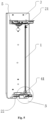
- 1 electric heating plate; 2: cross beam; 21: upper cross beam; 211: connecting piece; 2111: first through hole; 22: lower cross beam; 23: first fitting hole; 3: outer support; 31: second fitting hole; 32: left support; 33: right support; 4: first support; 41: groove; 411: side wall; 4111: notch; 4112: side plate; 4113: rib; 4114: reinforcing rib; 4115: buckle structure; 412: bottom wall; 413: U-shaped groove; 42: wire layout hole; 43: wire layout groove; 5: insulating structure; 51: first connecting portion; 511: first buckle; 52: second connecting portion; 521: second buckle; 522: first screw; 53: body; 54: protruding structure; 541: second screw; 542: reinforcing rib.
- the present invention provides an electric heating plate fixing structure of an electric heater, and an electric heater including the electric heating plate fixing structure.
- the electric heating plate fixing structure includes a cross beam 2 and an outer support 3, the cross beam 2 is supported by the outer support 3, the cross beam 2 includes a lower cross beam 22, a first support 4 is provided between the lower end of the electric heating plate 1 and the lower cross beam 22, and the first support 4 is provided with a groove 41 or a buckle.
- the electric heating plate fixing structure includes a cross beam 2 and an outer support 3
- the cross beam 2 is supported by the outer support 3
- the cross beam 2 includes a lower cross beam 22
- a first support 4 is provided between the lower end of the electric heating plate 1 and the lower cross beam 22
- the first support 4 is provided with a groove 41 or a buckle.
- the first support 4 is provided with a plurality of grooves 41, the number of the grooves 41 matches the number of the electric heating plates 1 of the electric heater, the lower end of the electric heating plate 1 is inserted into the groove 41, the electric heating plate 1 is clamped in the groove 41, the groove 41 can limit the position of the electric heating plate 1, and the electric heating plate 1 is fixed by the groove 41, that is, the electric heating plate 1 is connected with the lower cross beam 22 by the first support 4.
- the number of the grooves 41 matches the number of the electric heating plates 1 of the electric heater
- the lower end of the electric heating plate 1 is inserted into the groove 41
- the electric heating plate 1 is clamped in the groove 41
- the groove 41 can limit the position of the electric heating plate 1
- the electric heating plate 1 is fixed by the groove 41, that is, the electric heating plate 1 is connected with the lower cross beam 22 by the first support 4.
- the cross beam 2 further includes an upper cross beam 21, the upper end of the electric heating plate 1 is connected with the upper cross beam 21 by a fastener, the fastener is a bolt assembly, a screw assembly or a buckle assembly, and the bolt assembly is used here; preferably, the upper cross beam 21 is provided with a connecting piece 211 protruding toward the direction of the electric heating plate 1, the connecting piece 211 is provided with a threaded hole, and the electric heating plate 1 is directly fixed on the connecting piece 211 by a bolt so as to achieve the connection between the electric heating plate 1 and the upper cross beam 21, so that the connection is simple, time-saving and labor-saving, and the connection strength is high.
- the electric heating plate 1 can also be connected with the upper cross beam 21 by the first support 4, and the specific connecting manner will not be redundantly repeated here.
- two ends of the upper cross beam 21 are respectively connected with the outer support 3 by insulating structures 5; preferably, the insulating structure 5 is made of a plastic material, which is easy to process and shape, and is low in cost; the insulating structure 5 is in a threaded connection or a snap-fit connection with the upper cross beam 21; likewise, the insulating structure 5 is also in a threaded connection or a snap-fit connection with the outer support 3, so as to ensure the firmness of the connection, and the insulation between the upper cross beam 21 and the outer support 3.
- the first support 4 is also made of an insulating material, preferably a plastic material, which is easy to process and shape, is low in cost, and can ensure a high connection strength; by the insulating structure 5 and the first support 4, the electric heating plats 1 can be insulated from the outer support 3, and by the fixing structure above, the original ceramic base assembly is omitted, achieving the advantages of convenient connection, simple assembly, and high efficiency, thereby greatly reducing labor costs.
- connection manner between the first support 4 and the electric heating plate 1 is not limited to the connection manner of groove 41 or buckle, and the connection manner can also be a threaded connection, by providing, on the electric heating plate 1 and the first support 4, connecting holes which match with each other, and then achieving connection by stud or screw, and this can also satisfy the requirement for connection and insulation, and the first support 4 can also in a snap-fit connection or a threaded connection with the lower cross beam 22.
- the electric heating plate 1 of the electric heater is fixed by the first support 4, so that the operation process is simple, the man-hour on the assembly process can be greatly shortened, the efficiency is obviously improved, which can be increased by about 48%.
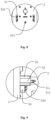
- the groove 41 includes side walls 411 and a bottom wall 412, wherein one end of each of the side walls 411 is connected to the bottom wall 412, the other end of each of the side walls 411 is a free end, notches 4111 are provided on the side walls 411, and the notches 4111 extend from the free end toward the bottom wall 412.
- the notches 4111 extend from the free end to the upper surface of the bottom wall 412, so that a plurality of side plates 4112 that are provided at intervals are formed on the side walls 411, and this can reduce the amount of material used for the first support 4, reducing costs.
- the notches 4111 divide the sides of the groove 41 into a plurality of side plates 4112, the elasticity of the side plates 4112 can be increased, thereby facilitating the installation of the electric heating plate 1.
- a rib 4113 is provided on the inner wall surfaces of part of the side plates 4112 of the groove 41, which are used for clamping the electric heating plate 1 in the groove 41.
- the provision of the notches 4111 facilitates the processing of the groove 41, reducing labor costs and time costs.
- Reinforcing ribs 4114 are provided on at least part of the outer wall surfaces of the side plates 4112.
- the reinforcing ribs 4114 are provided on the outer wall surfaces of all the side plates 4112, and the rib 4113 is provided on the inner wall surfaces of all the side plates 4112.
- Each of the rib 4113 forms a U-shaped groove 413 in a direction toward an opening of the groove 41.
- the opening of the U-shaped groove 413 and the opening of the groove 41 face a same direction, so as to ensure the stability and security of the connection between the first support 4 and the electric heating plate 1.
- the reinforcing ribs 4114 can be provided on the outer wall surfaces of a part of the side plates 4112, and the ribs 4113 are provided on the inner wall surfaces of the other part of the side plates 4112, thereby reducing the material cost.
- the side plates 4112 on which the reinforcing ribs 4114 are provided and the side plates 4112 on which the ribs 4113 are provided are alternatively arranged.
- the reinforcing ribs 4114 and the ribs 4113 are arranged alternatively on the connection between the electrical heating plate 1 and the first support 4, ensuring the strength of the connection, and improving the service life of the electric heater.
- the inner walls of part of the side plates 4112 are provided with buckles 4115.
- the buckles 4115 are provided on the inner walls of the side plates 4112 having the reinforcing ribs 4114. As shown in Fig.
- each of the buckles 4115 includes a first buckle portion and a second buckle portion, the first buckle portion and the second buckle portion are disposed on the inner side surfaces of two opposite side walls of the groove, and are provided opposite to each other.
- the snap-fit part of each one of the first buckle portion and the second buckle portion extends toward the direction of the other of the first portion and the second buckle portion.
- the end portion of the electric heating plate 1 is provided with a protruding structure, and the protruding structure can pass through the first buckle portion and the second buckle portion to be located on the lower side of the buckle 4115, so that the end portion of the electric heating plate 1 can be fixed by the buckle structure 4115.
- a plurality of buckles 4115 are provided on each of the grooves 41, and there are three buckles in total in the embodiment shown in Fig. 4 .
- the number of buckles is not particularly limited, as long as the electric heating plate 1 can be firmly fixed.
- the bottom wall 412 is provided with a wire layout hole 42 and/or a wire layout groove 43.
- the wire layout hole 42 and the wire layout groove 43 are both provided, and a folded edge structure that is folded toward the direction away from the groove 41 is provided around the lower cross beam 22.
- the structural strength of the lower cross beam 22 can be improved, and on the other hand, space for the wire arrangement of the electric heater can be provided.
- the first support 4 is provided with cylindrical structure protruding toward the direction of the lower cross beam 22, and the lower cross beam 22 is provided with a first fitting hole fitted with the cylindrical structure, the cylindrical structure is provided with a through hole, and the cylindrical structure is the wire layout holes 42 used for the passage of the wires.
- the first support 4 is provided with the wire layout groove 43 protruding toward the direction of the lower cross beam 22
- the lower cross beam 22 is provided with second fitting hole fitted with the wire layout groove structure
- the wire layout groove 43 is used for the arrangement of the wires
- the wire layout groove 43 includes two elastic clamping arms disposed opposite to each other, so as to ensure the close fitting between the wire layout groove 43 and the second fitting hole, and furthermore, it is more convenient to arrange the wires, and the safety of the arrangement of wires in the wire layout groove 43 is improved.
- the wires of the electric heating plate 1 are fixed in the wire layout hole 42 and the wire layout groove 43 of the first support 4, so that the wire arrangement is more reasonable and the assembly efficiency is high, solving the hidden troubles of the wiring being complicated and the wires being easy to be scratched in the prior art.
- the first support 4 is made of a plastic material, the processing is convenient, and compared with sheet metal materials, the hidden trouble of burrs scratching the wires can further be avoided.
- one end of the electric heating plate 1 of the electric heater is directly fixed on the upper cross beam 21 by a threaded connection, and the other end is directly inserted into the groove 41 of the first support 4 which is made of a plastic material, and is directly fixed by the groove 41 of the first support 4, so that the installation is simple.
- the first support 4 is provided with the wire layout hole 42 and the wire layout groove 43, and the wires of the electric heating plate 1 are fixed in the wire layout hole 42 and the wire layout grooves 43 of the first support 4, so that the assembly efficiency is high, solving the hidden troubles of the wiring being complicated and the wires being easy to be scratched in the prior art.
- the electric heating plate 1 is directly connected with the upper cross beam 21.
- the upper cross beam 21 and the outer support 3 are connected by the insulating structure 5.
- the insulating structure 5 is connected with the upper cross beam 21 and the outer support 3 respectively, thereby ensuring that the upper cross beam 21 and the outer support 3 are not in direct contact, so that the upper cross beam 21 is in an insulated connection with the outer support 3.
- the electric heating plate 1 is directly connected with the upper cross beam 21, the insulation between the electric heating plate 1 and the outer support 3 can also be achieved.
- the original ceramic base assembly is omitted, which has a relatively high assembly difficulty, solving the problems of low assembly efficiency and labor consumption when the electric heating plates 1 are fixed by the ceramic base assemblies in the prior art, and greatly reducing the production cost of products.
- the upper cross beam 21 is in a snap-fit connection and/or a threaded connection with the insulating structure 5
- the outer support 3 is in a snap-fit connection and/or a threaded connection with the insulating structure 5.
- the snap-fit connection and/or the threaded connection above between the insulating structure 5 and the upper cross beam 21 and between the insulating structure 5 and the outer support 3 can be used separately, or the two connections can both be used or can be used alternatively, that is, the snap-fit connection or the threaded connection can be used in both the connection between the insulating structures 5 and the upper cross beam 21 and the connection between the insulating structures 5 and the outer support 3, or the snap-fit connection and the threaded connection can both be used in the two connections, or the snap-fit connection can be used in one connection, and the threaded connection can be used in the other connection, as long as the upper cross beam 21 and the outer support 3 are insulated from each other by the insulating structure 5.
- other connection manners can also be used, such as bonding.
- the upper cross beam 21 and the insulating structure 5 are connected by using both the snap-fit connection and the threaded connection
- the insulating structure 5 and the outer support 3 are also connected by using both the snap-fit connection and the threaded connection.
- the insulating structure 5 includes a protruding structure 54
- the protruding structure 54 is disposed on one side, close to the outer support 3, of the body 53, or the protruding structure 54 is disposed on a lower side or an upper side of the body 53 (for ease of description, in the present invention, a side directly facing the viewer in Fig.
- the protruding portion of the protruding structure 54 is in a threaded connection with the outer support 3, so as to ensure the stability of the connection between the insulating structure 5 and the outer support 3, and the protruding structure 54 includes a reinforcing rib 542, so as to enhance the strength and stability of the protruding structure 54.
- the insulating structure 5 includes a body 53, and a first connecting portion 51 and a second connecting portion 52 which are respectively disposed at two sides of the body 53, wherein, the first connecting portion 51 is used for the connection between the insulating structure 5 and the upper cross beam 21, and the second connecting portion 52 is used for the connection between the insulating structure 5 and the outer support 3. Furthermore, the first connecting portion 51 includes a first buckle 511, the upper cross beam 21 is provided with a first fitting hole 23 fitted with the first buckle 511.
- the first buckle 511 includes a pair of buckles oppositely provided on a front side and a rear side of the body 53, and a snap-fit part of each one of the pair of buckles extends toward a direction where the other one of the pair of buckles located, thereby realizing the fixation by the snap-fit connection, and guaranteeing the effective of the snap-fit connection, so that the insulating structure 5 is in a firmly snap-fit connection with the upper cross beam 21.
- a first screw 522 is also used to connect the body 53 of the insulating structure 5 and the upper cross beam 21, so as to ensure the connection strength and prevent the influence caused by the falling off of the first buckle 511.
- the second connecting portion 52 includes a second buckle 521, a second fitting hole 31 fitted with the second buckle 521 is provided on the outer support 3,
- the second buckle 521 includes a plurality of pairs of buckles provided on a front side and a rear side of the body 53, the plurality of pairs of buckles are arranged in sequence in an up-down direction, the provision of the plurality of pairs of buckles can effectively ensure the stable snap-fit connection between the insulating structure 5 and the outer support 3, so as to improve the reliability of the connection; preferably, there are two pairs of buckles, and in the up-down direction, the first connecting portion 51 is disposed between the two pairs of second buckles 521, so that the whole construction of the insulating structure 5 is reasonable, thereby ensuring the connection strength between the insulating structure 5 and the upper cross beam 21 and the connection strength between the insulating structure 5 and the outer support 3, and ensuring the stability of the overall structure formed after the insulating structure 5 is connected with the outer support
- the insulating structure 5 is made of a non-conductive material, preferably a plastic material, which has good insulating property, is easy to process, and has a low cost.
- the cross beam 2 includes an upper cross beam 21 and a lower cross beam 22
- the outer support 3 includes a left support 32 and a right support 33
- the upper cross beam 21 is connected with the left support 32 and the right support 33 respectively through the insulating structure 5
- the lower cross beam 22 is in a threaded connection with the left support 32 and the right support 33 respectively
- the electric heating plate 1 is in a directly threaded connection with the upper cross beam 21
- the electric heating plate 1 is connected with the lower cross beam 22 by the first support 4
- the cross beam 2 and the outer support 3 are made into a structure which is separable in the up-down and left-right directions, so as to facilitate the connection operation of an operator, improving the connection efficiency, and reducing the installation time
- the electric heater includes a plurality of electric heating plates 1 which are fixed on the upper cross beam 21 and the lower cross beam 22, and are disposed between the left support 32 and the right support 33, so as to provide a good heating effect, and to better satisfy user requirements.
Landscapes
- Engineering & Computer Science (AREA)
- Physics & Mathematics (AREA)
- Thermal Sciences (AREA)
- Chemical & Material Sciences (AREA)
- Combustion & Propulsion (AREA)
- Mechanical Engineering (AREA)
- General Engineering & Computer Science (AREA)
- Central Heating Systems (AREA)
- Resistance Heating (AREA)
Claims (14)
- Befestigungsstruktur für elektrische Heizplatten einer elektrischen Heizvorrichtung, umfassend einen Querträger (2), eine äußere Stütze (3) und eine erste Stütze (4), wobei der Querträger (2) mit der äußeren Stütze (3) verbunden ist, die erste Stütze (4) zum Verbinden einer elektrischen Heizplatte (1) der elektrischen Heizvorrichtung verbunden ist, die erste Stütze (4) mit dem Querträger (2) verbunden ist,der Querträger (2) einen oberen Querträger (21) und einen unteren Querträger (22) umfasst, die erste Stütze (4) mit dem unteren Querträger (22) verbunden ist unddie elektrische Heizplatte (1) mit dem oberen Querträger (21) verbunden ist,wobei die elektrische Heizplatte dadurch gekennzeichnet ist, dass der obere Querträger (21) durch eine Isolierstruktur (5) mit der äußeren Stütze (3) verbunden ist.
- Befestigungsstruktur für elektrische Heizplatten nach Anspruch 1, wobei sich die erste Stütze (4) in einer Schnappverschlussverbindung und/oder einer Gewindeverbindung mit dem Querträger (2) befindet; und/oder sich die erste Stütze (4) in einer Schnappverschlussverbindung und/oder einer Gewindeverbindung mit der äußeren Stütze (3) befindet.
- Befestigungsstruktur für elektrische Heizplatten nach Anspruch 2, wobei die erste Stütze (4) mit einer Nut (41) bereitgestellt ist und ein Ende der elektrischen Heizplatte (1) in die Nut (41) eingeführt ist.
- Befestigungsstruktur für elektrische Heizplatten nach Anspruch 3, wobei eine Vielzahl von Nuten (41) und eine Vielzahl von elektrischen Heizplatten (1) vorhanden sind und jede von der Vielzahl von elektrischen Heizplatten (1) einer Nut der Vielzahl von Nuten (41) entspricht.
- Befestigungsstruktur für elektrische Heizplatten nach Anspruch 3, wobei die Nut (41) Seitenwände (411) und eine untere Wand (412) umfasst, wobei ein Ende von jeder der Seitenwände (411) mit der unteren Wand (412) verbunden ist und das andere Ende von jeder der Seitenwände (411) ein freies Ende ist.
- Befestigungsstruktur für elektrische Heizplatten nach Anspruch 5, wobei jede der Seitenwände (411) mit einer Schnallenstruktur (4115) bereitgestellt ist, wobei die Schnallenstruktur (4115) einen ersten Schnallenabschnitt und einen zweiten Schnallenabschnitt umfasst, wobei der erste Schnallenabschnitt und der zweite Schnallenabschnitt auf inneren Seitenfläche von zwei gegenüberliegenden Seitenwänden (411) der Nut (41) angeordnet sind und gegenüber einander bereitgestellt sind und sich ein Schnappverschlussteil von jedem von dem ersten Schnallenabschnitt und dem zweiten Schnallenabschnitt hin zu einer Richtung erstreckt, in der sich der andere von dem ersten Schnallenabschnitt und dem zweiten Schnallenabschnitt befindet.
- Befestigungsstruktur für elektrische Heizplatten nach Anspruch 6, wobei eine Vielzahl von Schnallenstrukturen (4115) an der Nut (41) bereitgestellt ist.
- Befestigungsstruktur für elektrische Heizplatten nach Anspruch 5, wobei innere Seiten der Seitenwände (411) mit einer Rippe (4113) bereitgestellt sind, wobei die Rippe (4113) auf zwei gegenüberliegenden Flächen der Seitenwände (411) bereitgestellt sind, wobei die Rippe (4113) in einer Richtung hin zu einer Öffnung der Nut (411) eine U-förmige Nut (413) bildet und eine Öffnung der U-förmigen Nut (413) und die Öffnung der Nut (411) derselben Richtung zugewandt sind.
- Befestigungsstruktur für elektrische Heizplatten nach Anspruch 5, wobei der Querträger (2) einen unteren Querträger (22) umfasst, die untere Wand (412) an dem unteren Querträger (22) befestigt ist und die untere Wand (412) mit einem Drahtausführungsloch (42) und/oder einer Drahtausführungsnut (43) bereitgestellt ist.
- Befestigungsstruktur für elektrische Heizplatten nach Anspruch 1, wobei ein unteres Ende der elektrischen Heizplatte (1) mit der ersten Stütze (4) verbunden ist und ein oberes Ende der elektrischen Heizplatte (1) mit dem oberen Querträger (21) verbunden ist.
- Befestigungsstruktur für elektrische Heizplatten nach Anspruch 1, wobei sich der obere Querträger (21) in einer Schnappverschlussverbindung und/oder in einer Gewindeverbindung mit der Isolierstruktur (5) befindet; und/oder sich die äußere Stütze (3) in einer Schnappverschlussverbindung und/oder einer Gewindeverbindung mit der Isolierstruktur (5) befindet.
- Befestigungsstruktur für elektrische Heizplatten nach Anspruch 11, wobei die Isolierstruktur (5) aus einem nicht leitfähigen Material hergestellt ist und einen Körper (53) und einen ersten Verbindungsabschnitt (51) und einen zweiten Verbindungsabschnitt (52) umfasst, die sich jeweils auf zwei Seiten des Körpers (53) befinden, wobei der erste Verbindungsabschnitt (51) für die Verbindung zwischen der Isolierstruktur (5) und dem oberen Querträger (21) verwendet wird und der zweite Verbindungsabschnitt (52) für die Verbindung zwischen der Isolierstruktur (5) und der oberen Stütze (3) verwendet wird.
- Befestigungsstruktur für elektrische Heizplatten nach Anspruch 12, wobei der erste Verbindungsabschnitt (51) eine erste Schnalle (511) umfasst, der obere Querträger (21) mit einem ersten Passloch (23) bereitgestellt ist, das mit der ersten Schnalle (511) zusammenpasst, die erste Schnalle (511) ein Paar von Schnallen umfasst, die an einer Vorderseite und einer Rückseite des Körpers (53) gegenüberliegend bereitgestellt sind, und sich ein Schnappverschlussteil von jeder von dem Paar von Schnallen zu einer Richtung hin erstreckt, in der sich die andere von dem Paar von Schnallen befindet; und/oder der zweite Verbindungsabschnitt (52) eine zweite Schnalle (521) umfasst und der äußere Träger (3) mit einem zweiten Passloch (31) bereitgestellt ist, das mit der zweiten Schnalle (521) zusammenpasst, die zweite Schnalle (521) eine Vielzahl von Paaren von Schnallen umfasst, die an einer Vorderseite und einer Rückseite des Körpers (53) bereitgestellt ist, und die Vielzahl von Paar von Schnallen in einer Richtung von oben nach unten sequentiell angeordnet ist.
- Elektrische Heizvorrichtung, wobei eine elektrische Heizplatte (1) der elektrischen Heizvorrichtung durch eine Befestigungsstruktur nach einem der Ansprüche 1 bis 13 befestigt ist.
Applications Claiming Priority (2)
| Application Number | Priority Date | Filing Date | Title |
|---|---|---|---|
| CN201810708587.XA CN108826435B (zh) | 2018-07-02 | 2018-07-02 | 电暖气的电热片固定结构及电暖气 |
| PCT/CN2018/122310 WO2020006995A1 (zh) | 2018-07-02 | 2018-12-20 | 电暖气的电热片固定结构及电暖气 |
Publications (3)
| Publication Number | Publication Date |
|---|---|
| EP3819552A1 EP3819552A1 (de) | 2021-05-12 |
| EP3819552A4 EP3819552A4 (de) | 2021-08-25 |
| EP3819552B1 true EP3819552B1 (de) | 2023-06-14 |
Family
ID=64134862
Family Applications (1)
| Application Number | Title | Priority Date | Filing Date |
|---|---|---|---|
| EP18925557.3A Active EP3819552B1 (de) | 2018-07-02 | 2018-12-20 | Befestigungsstruktur für elektrische heizplatten einer elektrischen heizvorrichtung und elektrische heizvorrichtung |
Country Status (3)
| Country | Link |
|---|---|
| EP (1) | EP3819552B1 (de) |
| CN (1) | CN108826435B (de) |
| WO (1) | WO2020006995A1 (de) |
Families Citing this family (3)
| Publication number | Priority date | Publication date | Assignee | Title |
|---|---|---|---|---|
| CN108826435B (zh) * | 2018-07-02 | 2020-06-19 | 珠海格力电器股份有限公司 | 电暖气的电热片固定结构及电暖气 |
| CN109769312A (zh) * | 2019-03-04 | 2019-05-17 | 珠海格力电器股份有限公司 | 一种横梁组件、电热膜片安装框架及取暖设备 |
| CN111457452A (zh) * | 2020-05-18 | 2020-07-28 | 珠海格力电器股份有限公司 | 取暖器 |
Family Cites Families (10)
| Publication number | Priority date | Publication date | Assignee | Title |
|---|---|---|---|---|
| JP2005085696A (ja) * | 2003-09-10 | 2005-03-31 | Denso Corp | 電気式ヒータ |
| CN202303622U (zh) | 2011-09-02 | 2012-07-04 | 格力电器(中山)小家电制造有限公司 | 一种电热膜式电暖器 |
| CN202361471U (zh) * | 2011-12-16 | 2012-08-01 | 雷中彬 | 一种电暖气 |
| CN206439897U (zh) * | 2016-12-15 | 2017-08-25 | 新疆澳德普盛节能科技有限公司 | 一种电暖气 |
| CN206600862U (zh) * | 2017-02-14 | 2017-10-31 | 鞍兆(中山)电器有限公司 | 一种新型ptc散热对流式取暖器 |
| CN207094750U (zh) * | 2017-07-18 | 2018-03-13 | 北京金坤万远科技有限公司 | 一种高效电暖气 |
| CN207378923U (zh) * | 2017-07-25 | 2018-05-18 | 南京怀萃智能科技有限公司 | 一种电暖气外壳及电暖气 |
| CN107781893A (zh) * | 2017-11-23 | 2018-03-09 | 珠海格力电器股份有限公司 | 电热膜发热结构及具有其的发热装置 |
| CN208652694U (zh) * | 2018-07-02 | 2019-03-26 | 珠海格力电器股份有限公司 | 电暖气的电热片固定结构及电暖气 |
| CN108826435B (zh) * | 2018-07-02 | 2020-06-19 | 珠海格力电器股份有限公司 | 电暖气的电热片固定结构及电暖气 |
-
2018
- 2018-07-02 CN CN201810708587.XA patent/CN108826435B/zh active Active
- 2018-12-20 EP EP18925557.3A patent/EP3819552B1/de active Active
- 2018-12-20 WO PCT/CN2018/122310 patent/WO2020006995A1/zh not_active Ceased
Also Published As
| Publication number | Publication date |
|---|---|
| CN108826435B (zh) | 2020-06-19 |
| EP3819552A1 (de) | 2021-05-12 |
| CN108826435A (zh) | 2018-11-16 |
| EP3819552A4 (de) | 2021-08-25 |
| WO2020006995A1 (zh) | 2020-01-09 |
Similar Documents
| Publication | Publication Date | Title |
|---|---|---|
| EP3819552B1 (de) | Befestigungsstruktur für elektrische heizplatten einer elektrischen heizvorrichtung und elektrische heizvorrichtung | |
| US11881698B2 (en) | Bus duct shell and bus duct | |
| KR102146064B1 (ko) | 분전반용 연결 브라켓 및 이를 구비한 분전반 | |
| WO2020029491A1 (zh) | 接线组件及具有其的空调器 | |
| KR200491844Y1 (ko) | 배터리모듈용 직렬연결장치 | |
| KR20140136152A (ko) | 정션박스 | |
| CN208424805U (zh) | 电暖气的电热片绝缘结构及电暖气 | |
| US4203146A (en) | Multiple metering panelboard assembly | |
| CN109084361B (zh) | 一种电热膜取暖器及该取暖器的组装方法 | |
| CN210468706U (zh) | 一种便于拆卸的母线槽连接器 | |
| KR101127495B1 (ko) | 조립식 배전함 | |
| CN205232653U (zh) | 过线装置和电控箱 | |
| JP2026504758A (ja) | エネルギー貯蔵装置及びそのケーシング | |
| CN108631242B (zh) | 母线外壳结构 | |
| KR101447117B1 (ko) | 클립타입의 부스바 커넥터 조립체 및 이를 포함하는 분전반 | |
| KR101610455B1 (ko) | 분전반의 부스바 고정클립 | |
| CN207743842U (zh) | 一种步进电机防护盖板以及步进电机连接结构 | |
| CN212542735U (zh) | 一种接线端子、接地线结构及空调器 | |
| CN206621182U (zh) | 电炊具温控器和电炊具 | |
| CN221962034U (zh) | 一种电气隔离结构及电气模块 | |
| JP2015204279A (ja) | 端子装置及び分電盤 | |
| CN109769312A (zh) | 一种横梁组件、电热膜片安装框架及取暖设备 | |
| CN216648865U (zh) | 一种连接构件、母排连接结构及配电柜 | |
| CN206291344U (zh) | 用于风管机的电辅热支撑组件及风管机 | |
| JP2544131B2 (ja) | 平形ケ−ブル支持金具 |
Legal Events
| Date | Code | Title | Description |
|---|---|---|---|
| STAA | Information on the status of an ep patent application or granted ep patent |
Free format text: STATUS: THE INTERNATIONAL PUBLICATION HAS BEEN MADE |
|
| PUAI | Public reference made under article 153(3) epc to a published international application that has entered the european phase |
Free format text: ORIGINAL CODE: 0009012 |
|
| STAA | Information on the status of an ep patent application or granted ep patent |
Free format text: STATUS: REQUEST FOR EXAMINATION WAS MADE |
|
| 17P | Request for examination filed |
Effective date: 20201217 |
|
| AK | Designated contracting states |
Kind code of ref document: A1 Designated state(s): AL AT BE BG CH CY CZ DE DK EE ES FI FR GB GR HR HU IE IS IT LI LT LU LV MC MK MT NL NO PL PT RO RS SE SI SK SM TR |
|
| A4 | Supplementary search report drawn up and despatched |
Effective date: 20210723 |
|
| RIC1 | Information provided on ipc code assigned before grant |
Ipc: F24D 19/02 20060101AFI20210719BHEP Ipc: H05B 3/22 20060101ALI20210719BHEP Ipc: H05B 3/06 20060101ALI20210719BHEP |
|
| DAV | Request for validation of the european patent (deleted) | ||
| DAX | Request for extension of the european patent (deleted) | ||
| GRAP | Despatch of communication of intention to grant a patent |
Free format text: ORIGINAL CODE: EPIDOSNIGR1 |
|
| STAA | Information on the status of an ep patent application or granted ep patent |
Free format text: STATUS: GRANT OF PATENT IS INTENDED |
|
| INTG | Intention to grant announced |
Effective date: 20230321 |
|
| GRAS | Grant fee paid |
Free format text: ORIGINAL CODE: EPIDOSNIGR3 |
|
| GRAA | (expected) grant |
Free format text: ORIGINAL CODE: 0009210 |
|
| STAA | Information on the status of an ep patent application or granted ep patent |
Free format text: STATUS: THE PATENT HAS BEEN GRANTED |
|
| AK | Designated contracting states |
Kind code of ref document: B1 Designated state(s): AL AT BE BG CH CY CZ DE DK EE ES FI FR GB GR HR HU IE IS IT LI LT LU LV MC MK MT NL NO PL PT RO RS SE SI SK SM TR |
|
| REG | Reference to a national code |
Ref country code: CH Ref legal event code: EP |
|
| REG | Reference to a national code |
Ref country code: DE Ref legal event code: R096 Ref document number: 602018051991 Country of ref document: DE |
|
| P01 | Opt-out of the competence of the unified patent court (upc) registered |
Effective date: 20230530 |
|
| REG | Reference to a national code |
Ref country code: AT Ref legal event code: REF Ref document number: 1579469 Country of ref document: AT Kind code of ref document: T Effective date: 20230715 |
|
| REG | Reference to a national code |
Ref country code: LT Ref legal event code: MG9D |
|
| REG | Reference to a national code |
Ref country code: NL Ref legal event code: MP Effective date: 20230614 |
|
| PG25 | Lapsed in a contracting state [announced via postgrant information from national office to epo] |
Ref country code: SE Free format text: LAPSE BECAUSE OF FAILURE TO SUBMIT A TRANSLATION OF THE DESCRIPTION OR TO PAY THE FEE WITHIN THE PRESCRIBED TIME-LIMIT Effective date: 20230614 Ref country code: NO Free format text: LAPSE BECAUSE OF FAILURE TO SUBMIT A TRANSLATION OF THE DESCRIPTION OR TO PAY THE FEE WITHIN THE PRESCRIBED TIME-LIMIT Effective date: 20230914 Ref country code: ES Free format text: LAPSE BECAUSE OF FAILURE TO SUBMIT A TRANSLATION OF THE DESCRIPTION OR TO PAY THE FEE WITHIN THE PRESCRIBED TIME-LIMIT Effective date: 20230614 |
|
| REG | Reference to a national code |
Ref country code: AT Ref legal event code: MK05 Ref document number: 1579469 Country of ref document: AT Kind code of ref document: T Effective date: 20230614 |
|
| PG25 | Lapsed in a contracting state [announced via postgrant information from national office to epo] |
Ref country code: RS Free format text: LAPSE BECAUSE OF FAILURE TO SUBMIT A TRANSLATION OF THE DESCRIPTION OR TO PAY THE FEE WITHIN THE PRESCRIBED TIME-LIMIT Effective date: 20230614 Ref country code: NL Free format text: LAPSE BECAUSE OF FAILURE TO SUBMIT A TRANSLATION OF THE DESCRIPTION OR TO PAY THE FEE WITHIN THE PRESCRIBED TIME-LIMIT Effective date: 20230614 Ref country code: LV Free format text: LAPSE BECAUSE OF FAILURE TO SUBMIT A TRANSLATION OF THE DESCRIPTION OR TO PAY THE FEE WITHIN THE PRESCRIBED TIME-LIMIT Effective date: 20230614 Ref country code: LT Free format text: LAPSE BECAUSE OF FAILURE TO SUBMIT A TRANSLATION OF THE DESCRIPTION OR TO PAY THE FEE WITHIN THE PRESCRIBED TIME-LIMIT Effective date: 20230614 Ref country code: HR Free format text: LAPSE BECAUSE OF FAILURE TO SUBMIT A TRANSLATION OF THE DESCRIPTION OR TO PAY THE FEE WITHIN THE PRESCRIBED TIME-LIMIT Effective date: 20230614 Ref country code: GR Free format text: LAPSE BECAUSE OF FAILURE TO SUBMIT A TRANSLATION OF THE DESCRIPTION OR TO PAY THE FEE WITHIN THE PRESCRIBED TIME-LIMIT Effective date: 20230915 |
|
| PG25 | Lapsed in a contracting state [announced via postgrant information from national office to epo] |
Ref country code: FI Free format text: LAPSE BECAUSE OF FAILURE TO SUBMIT A TRANSLATION OF THE DESCRIPTION OR TO PAY THE FEE WITHIN THE PRESCRIBED TIME-LIMIT Effective date: 20230614 |
|
| PG25 | Lapsed in a contracting state [announced via postgrant information from national office to epo] |
Ref country code: SK Free format text: LAPSE BECAUSE OF FAILURE TO SUBMIT A TRANSLATION OF THE DESCRIPTION OR TO PAY THE FEE WITHIN THE PRESCRIBED TIME-LIMIT Effective date: 20230614 |
|
| PG25 | Lapsed in a contracting state [announced via postgrant information from national office to epo] |
Ref country code: IS Free format text: LAPSE BECAUSE OF FAILURE TO SUBMIT A TRANSLATION OF THE DESCRIPTION OR TO PAY THE FEE WITHIN THE PRESCRIBED TIME-LIMIT Effective date: 20231014 |
|
| PG25 | Lapsed in a contracting state [announced via postgrant information from national office to epo] |
Ref country code: SM Free format text: LAPSE BECAUSE OF FAILURE TO SUBMIT A TRANSLATION OF THE DESCRIPTION OR TO PAY THE FEE WITHIN THE PRESCRIBED TIME-LIMIT Effective date: 20230614 Ref country code: SK Free format text: LAPSE BECAUSE OF FAILURE TO SUBMIT A TRANSLATION OF THE DESCRIPTION OR TO PAY THE FEE WITHIN THE PRESCRIBED TIME-LIMIT Effective date: 20230614 Ref country code: RO Free format text: LAPSE BECAUSE OF FAILURE TO SUBMIT A TRANSLATION OF THE DESCRIPTION OR TO PAY THE FEE WITHIN THE PRESCRIBED TIME-LIMIT Effective date: 20230614 Ref country code: PT Free format text: LAPSE BECAUSE OF FAILURE TO SUBMIT A TRANSLATION OF THE DESCRIPTION OR TO PAY THE FEE WITHIN THE PRESCRIBED TIME-LIMIT Effective date: 20231016 Ref country code: IS Free format text: LAPSE BECAUSE OF FAILURE TO SUBMIT A TRANSLATION OF THE DESCRIPTION OR TO PAY THE FEE WITHIN THE PRESCRIBED TIME-LIMIT Effective date: 20231014 Ref country code: EE Free format text: LAPSE BECAUSE OF FAILURE TO SUBMIT A TRANSLATION OF THE DESCRIPTION OR TO PAY THE FEE WITHIN THE PRESCRIBED TIME-LIMIT Effective date: 20230614 Ref country code: CZ Free format text: LAPSE BECAUSE OF FAILURE TO SUBMIT A TRANSLATION OF THE DESCRIPTION OR TO PAY THE FEE WITHIN THE PRESCRIBED TIME-LIMIT Effective date: 20230614 Ref country code: AT Free format text: LAPSE BECAUSE OF FAILURE TO SUBMIT A TRANSLATION OF THE DESCRIPTION OR TO PAY THE FEE WITHIN THE PRESCRIBED TIME-LIMIT Effective date: 20230614 |
|
| PG25 | Lapsed in a contracting state [announced via postgrant information from national office to epo] |
Ref country code: PL Free format text: LAPSE BECAUSE OF FAILURE TO SUBMIT A TRANSLATION OF THE DESCRIPTION OR TO PAY THE FEE WITHIN THE PRESCRIBED TIME-LIMIT Effective date: 20230614 |
|
| REG | Reference to a national code |
Ref country code: DE Ref legal event code: R097 Ref document number: 602018051991 Country of ref document: DE |
|
| PLBE | No opposition filed within time limit |
Free format text: ORIGINAL CODE: 0009261 |
|
| STAA | Information on the status of an ep patent application or granted ep patent |
Free format text: STATUS: NO OPPOSITION FILED WITHIN TIME LIMIT |
|
| PG25 | Lapsed in a contracting state [announced via postgrant information from national office to epo] |
Ref country code: DK Free format text: LAPSE BECAUSE OF FAILURE TO SUBMIT A TRANSLATION OF THE DESCRIPTION OR TO PAY THE FEE WITHIN THE PRESCRIBED TIME-LIMIT Effective date: 20230614 |
|
| PG25 | Lapsed in a contracting state [announced via postgrant information from national office to epo] |
Ref country code: SI Free format text: LAPSE BECAUSE OF FAILURE TO SUBMIT A TRANSLATION OF THE DESCRIPTION OR TO PAY THE FEE WITHIN THE PRESCRIBED TIME-LIMIT Effective date: 20230614 |
|
| 26N | No opposition filed |
Effective date: 20240315 |
|
| PG25 | Lapsed in a contracting state [announced via postgrant information from national office to epo] |
Ref country code: SI Free format text: LAPSE BECAUSE OF FAILURE TO SUBMIT A TRANSLATION OF THE DESCRIPTION OR TO PAY THE FEE WITHIN THE PRESCRIBED TIME-LIMIT Effective date: 20230614 Ref country code: IT Free format text: LAPSE BECAUSE OF FAILURE TO SUBMIT A TRANSLATION OF THE DESCRIPTION OR TO PAY THE FEE WITHIN THE PRESCRIBED TIME-LIMIT Effective date: 20230614 |
|
| REG | Reference to a national code |
Ref country code: CH Ref legal event code: PL |
|
| PG25 | Lapsed in a contracting state [announced via postgrant information from national office to epo] |
Ref country code: LU Free format text: LAPSE BECAUSE OF NON-PAYMENT OF DUE FEES Effective date: 20231220 |
|
| PG25 | Lapsed in a contracting state [announced via postgrant information from national office to epo] |
Ref country code: MC Free format text: LAPSE BECAUSE OF FAILURE TO SUBMIT A TRANSLATION OF THE DESCRIPTION OR TO PAY THE FEE WITHIN THE PRESCRIBED TIME-LIMIT Effective date: 20230614 |
|
| GBPC | Gb: european patent ceased through non-payment of renewal fee |
Effective date: 20231220 |
|
| REG | Reference to a national code |
Ref country code: BE Ref legal event code: MM Effective date: 20231231 |
|
| PG25 | Lapsed in a contracting state [announced via postgrant information from national office to epo] |
Ref country code: MC Free format text: LAPSE BECAUSE OF FAILURE TO SUBMIT A TRANSLATION OF THE DESCRIPTION OR TO PAY THE FEE WITHIN THE PRESCRIBED TIME-LIMIT Effective date: 20230614 Ref country code: LU Free format text: LAPSE BECAUSE OF NON-PAYMENT OF DUE FEES Effective date: 20231220 |
|
| REG | Reference to a national code |
Ref country code: IE Ref legal event code: MM4A |
|
| PG25 | Lapsed in a contracting state [announced via postgrant information from national office to epo] |
Ref country code: IE Free format text: LAPSE BECAUSE OF NON-PAYMENT OF DUE FEES Effective date: 20231220 |
|
| PG25 | Lapsed in a contracting state [announced via postgrant information from national office to epo] |
Ref country code: GB Free format text: LAPSE BECAUSE OF NON-PAYMENT OF DUE FEES Effective date: 20231220 |
|
| PG25 | Lapsed in a contracting state [announced via postgrant information from national office to epo] |
Ref country code: BE Free format text: LAPSE BECAUSE OF NON-PAYMENT OF DUE FEES Effective date: 20231231 |
|
| PG25 | Lapsed in a contracting state [announced via postgrant information from national office to epo] |
Ref country code: CH Free format text: LAPSE BECAUSE OF NON-PAYMENT OF DUE FEES Effective date: 20231231 |
|
| PG25 | Lapsed in a contracting state [announced via postgrant information from national office to epo] |
Ref country code: IE Free format text: LAPSE BECAUSE OF NON-PAYMENT OF DUE FEES Effective date: 20231220 Ref country code: GB Free format text: LAPSE BECAUSE OF NON-PAYMENT OF DUE FEES Effective date: 20231220 Ref country code: CH Free format text: LAPSE BECAUSE OF NON-PAYMENT OF DUE FEES Effective date: 20231231 Ref country code: BE Free format text: LAPSE BECAUSE OF NON-PAYMENT OF DUE FEES Effective date: 20231231 |
|
| PG25 | Lapsed in a contracting state [announced via postgrant information from national office to epo] |
Ref country code: BG Free format text: LAPSE BECAUSE OF FAILURE TO SUBMIT A TRANSLATION OF THE DESCRIPTION OR TO PAY THE FEE WITHIN THE PRESCRIBED TIME-LIMIT Effective date: 20230614 |
|
| PG25 | Lapsed in a contracting state [announced via postgrant information from national office to epo] |
Ref country code: BG Free format text: LAPSE BECAUSE OF FAILURE TO SUBMIT A TRANSLATION OF THE DESCRIPTION OR TO PAY THE FEE WITHIN THE PRESCRIBED TIME-LIMIT Effective date: 20230614 |
|
| PG25 | Lapsed in a contracting state [announced via postgrant information from national office to epo] |
Ref country code: CY Free format text: LAPSE BECAUSE OF FAILURE TO SUBMIT A TRANSLATION OF THE DESCRIPTION OR TO PAY THE FEE WITHIN THE PRESCRIBED TIME-LIMIT; INVALID AB INITIO Effective date: 20181220 |
|
| PG25 | Lapsed in a contracting state [announced via postgrant information from national office to epo] |
Ref country code: HU Free format text: LAPSE BECAUSE OF FAILURE TO SUBMIT A TRANSLATION OF THE DESCRIPTION OR TO PAY THE FEE WITHIN THE PRESCRIBED TIME-LIMIT; INVALID AB INITIO Effective date: 20181220 |
|
| PG25 | Lapsed in a contracting state [announced via postgrant information from national office to epo] |
Ref country code: TR Free format text: LAPSE BECAUSE OF FAILURE TO SUBMIT A TRANSLATION OF THE DESCRIPTION OR TO PAY THE FEE WITHIN THE PRESCRIBED TIME-LIMIT Effective date: 20230614 |
|
| PGFP | Annual fee paid to national office [announced via postgrant information from national office to epo] |
Ref country code: FR Payment date: 20251110 Year of fee payment: 8 |
|
| PGFP | Annual fee paid to national office [announced via postgrant information from national office to epo] |
Ref country code: DE Payment date: 20251222 Year of fee payment: 8 |