EP3819443A1 - Vorrichtung zur erzeugung einer starken strömung in einem schwimmbecken mit mindestens einer lichtquelle - Google Patents
Vorrichtung zur erzeugung einer starken strömung in einem schwimmbecken mit mindestens einer lichtquelle Download PDFInfo
- Publication number
- EP3819443A1 EP3819443A1 EP19000601.5A EP19000601A EP3819443A1 EP 3819443 A1 EP3819443 A1 EP 3819443A1 EP 19000601 A EP19000601 A EP 19000601A EP 3819443 A1 EP3819443 A1 EP 3819443A1
- Authority
- EP
- European Patent Office
- Prior art keywords
- light source
- flow
- housing
- generating
- swimming pool
- Prior art date
- Legal status (The legal status is an assumption and is not a legal conclusion. Google has not performed a legal analysis and makes no representation as to the accuracy of the status listed.)
- Granted
Links
Images


Classifications
-
- E—FIXED CONSTRUCTIONS
- E04—BUILDING
- E04H—BUILDINGS OR LIKE STRUCTURES FOR PARTICULAR PURPOSES; SWIMMING OR SPLASH BATHS OR POOLS; MASTS; FENCING; TENTS OR CANOPIES, IN GENERAL
- E04H4/00—Swimming or splash baths or pools
- E04H4/0006—Devices for producing waves in swimming pools
-
- A—HUMAN NECESSITIES
- A63—SPORTS; GAMES; AMUSEMENTS
- A63B—APPARATUS FOR PHYSICAL TRAINING, GYMNASTICS, SWIMMING, CLIMBING, OR FENCING; BALL GAMES; TRAINING EQUIPMENT
- A63B69/00—Training appliances or apparatus for special sports
- A63B69/12—Arrangements in swimming pools for teaching swimming or for training
- A63B69/125—Devices for generating a current of water in swimming pools
-
- E—FIXED CONSTRUCTIONS
- E04—BUILDING
- E04H—BUILDINGS OR LIKE STRUCTURES FOR PARTICULAR PURPOSES; SWIMMING OR SPLASH BATHS OR POOLS; MASTS; FENCING; TENTS OR CANOPIES, IN GENERAL
- E04H4/00—Swimming or splash baths or pools
- E04H4/14—Parts, details or accessories not otherwise provided for
- E04H4/148—Lighting means
-
- A—HUMAN NECESSITIES
- A61—MEDICAL OR VETERINARY SCIENCE; HYGIENE
- A61H—PHYSICAL THERAPY APPARATUS, e.g. DEVICES FOR LOCATING OR STIMULATING REFLEX POINTS IN THE BODY; ARTIFICIAL RESPIRATION; MASSAGE; BATHING DEVICES FOR SPECIAL THERAPEUTIC OR HYGIENIC PURPOSES OR SPECIFIC PARTS OF THE BODY
- A61H33/00—Bathing devices for special therapeutic or hygienic purposes
- A61H33/005—Electrical circuits therefor
- A61H2033/0083—Illumination
Definitions
- the present invention relates to a device for generating a strong flow in a swimming pool with at least one light source, the light source being arranged in the immediate vicinity of the exit of the strong flow from the flow-generating system, in particular for receiving a plurality of light sources that indicate the operating state of the system, so that the system can be set according to the special needs of the user.
- a number of countercurrent systems are known in the art, e.g. B. WO 2015/176694 A1 and DE 20 2012 011 034 U1 all of which can create a strong current in a swimming pool. Also, under water lighting of a swimming pool are generally known. Furthermore, from the WO 2011/098576 A2 a wall trim with an LED strip has become known that can be used as lighting and marking the edge of the swimming pool.
- a measuring device has become known in which a plurality of sensors, inter alia light sources, are arranged in the area of the edge of a sink and display various parameters of the water that has built up in the sink.
- a disadvantage of the systems that have become known in the prior art is generally felt that the user of a swimming pool with a countercurrent system that generates a strong current, on the one hand, the location and, on the other hand, the condition of the system is not displayed, which leads to unpleasant contact of the user with the strong flow in the area where the flow exits the system.
- the present invention is based on the object of providing a device in the area of the flow outlet from a system for generating a strong current in a swimming pool, which is able to indicate the location and the operating status of the system.
- the device according to the invention for generating a strong flow in a swimming pool with a housing in which a flow-generating device is arranged is characterized by at least one light source which is arranged on or in the immediate vicinity of the housing of the device.
- the at least one light source is preferably arranged on the front of the housing of the device.
- the at least one light source is arranged in an annular holder for receiving the at least one light source.
- the radiation from the at least one light source is essentially perpendicular to the plane that is spanned by the annular holder. It is also advantageous that the ring-shaped holder is circular or polygonal or oval.
- At least one light source is arranged in the vicinity of the edge of at least one front outlet and / or the inlet opening of the flow-generating device.
- each individual light source can assume different colors, with each individual light source being able to be controlled and regulated electrically / electronically.
- control / regulation of the individual light sources is wireless or wired and at least the receiver of the control and regulation signals is designed to be watertight.
- the inlet and outlet openings in the housing of the device generating the strong flow are arranged almost in one plane. It is also advantageous that at least one light source has a signal function and, for example, indicates the operating state of the device.
- the ring-shaped holder is at least partially a component of the outlet opening of the system that generates the strong flow. Furthermore, it is considered advantageous that the at least one inlet and outlet opening is arranged on an at least partially curved surface. Another advantage is that the at least one light source can be an LED. Further advantageous properties and features of the present invention that are essential to the invention can be found in the subclaims and the description.
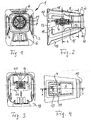
- the Fig. 1 shows a schematic front view of an exemplary embodiment of the device 1 with a housing 2 on which a plurality of light sources 5 are arranged in the form of a ring at the front in the immediate vicinity of the flow outlet 7.
- the housing 2 consists essentially of four side walls which, when put together, represent a pyramid-shaped body, the edges 18 of which are rounded.
- the sides have openings 6 through which the liquid or the water can enter the housing.
- the accelerated water jet emerging from the front of the outlet opening 7 forms a strong current within the swimming pool.
- the strong flow is generated by a flow-generating device which essentially consists of a drive 4 with a propeller 8.
- the drive is a direct current motor, the speed of which can be controlled almost continuously.
- an annular holder 11 is arranged, which receives a plurality of light sources 5.
- the Figure 2 shows a schematic side view of the funnel-shaped housing 2 of the device 1, in which a drive 4 with a propeller 8 and a holder 10 for receiving the at least one light source 5 is arranged on the front.
- the funnel-shaped housing 2 is asymmetrical in the side view for reasons of flow technology, the drive 4 being arranged more in the upper region of the housing 2.
- the drive 4 also has a propeller 8 with which the strong current is ultimately generated within the swimming pool.
- the drive 4 is attached to an adjustable suspension 13 so that the angle of the direction of flow to the water surface of the swimming pool can be adjusted.
- the drive 4 is arranged approximately up to halfway in a flow channel 15 which is largely funnel-shaped.
- the annular holder 10 has at least two screws or fastening means 14 with which the annular holder is fastened in the region of the outlet opening 7 of the housing 2 can be.
- the detachable fastening means such as screws 14, for example, have the advantage that the holder for receiving at least one light source 5 can be retrofitted later without dismantling the housing.
- a base element 17 is arranged on the side opposite the outlet opening 7, which base element serves both to fasten the housing 2 to the swimming pool wall and to fasten the adjustable suspension 13.
- FIG. 11 shows a schematic sectional illustration along the section line BB in FIG Figure 2 .
- the edges 18 of the housing 2 are rounded and thus contribute to the laminar flow within the housing 2.
- the drive 4 is arranged between two clamping plates 20 which are held together with two screw elements 21.
- the clamping elements 20, 21 are attached to the adjustable suspension 13.
- the Figure 4 shows a schematic plan view of the housing 2.
- the housing 2 is designed symmetrically to the center line AA and has large-area recesses 19 on all sides, which are designed as inlet openings 6 for the water of the swimming pool.
- the inlet openings 6 in the sides of the housing 2 are adapted approximately to the shape of the sides of the housing 2.
- the holder 10 for receiving at least one light source 5 is arranged in the immediate vicinity of the outlet opening 7.
- the holder 10 can vary both in the annular shape and in the size and is particularly suitable for retrofitting existing units for generating a strong current within a swimming pool.
- the Figure 5 shows a schematic perspective illustration of a further embodiment of a flow-generating unit in a round cylindrical housing 2 ', in which the water inlet 6' and the water outlet 7 'are arranged almost in one plane.
- the cylindrical shape of the housing 2 ' is fastened to a base ring 22 which in turn is fastened to the wall of the swimming pool with screws 23 or other fastening means.
- the drive 4 is attached to a suspension 13 'which is able to adjust the drive 4, in order to adjust the direction of flow or the angle of the direction of flow to the water surface.
- the water inlet 6 'and water outlet 7' are almost in one plane.
- the individual LED lights can take on different colors and are controlled electrically / electronically to indicate the operating status of the system.
- FIG. 11 shows a schematic side view of the exemplary embodiment from FIG Figure 5 , in which the flow channel 15 together with the drive 4 and the shell-shaped front side are arranged in and on the housing.
- a multiplicity of LED light sources 5, which are controlled by an electronic control system, not shown here, are arranged in the holder 10. To avoid repetition, refer to the description in Figure 5 pointed out.
- the Figure 7 shows a schematic representation of an exemplary embodiment of an annular holder 10 with a multiplicity of light sources 5.
- the light sources 5 are LED lights that can be controlled in different colors.
- the LED lights 5 are arranged on a circuit board 25, which in turn is subdivided into a plurality of sectors 26 in order, on the one hand, to facilitate the manufacture and repair or the exchangeability of a defective circuit board and, on the other hand, to enable electrical-electronic control .
- the inner diameter d of the ring-shaped holder 10 corresponds approximately to the corresponding outlet opening 7, which is to be identified by the ring-shaped holder 10 in the illuminated state.
- the Figure 8 shows a schematic side view of a front plate 24 of a housing, in which at least one annular holder 10 is installed, which surrounds at least one outlet opening 7 of the housing.
- the bracket 10 is made In simplified terms, it consists of the edge of the holder 10 and a part 27 offset therefrom, which is inserted into the outlet opening 7 in the front plate 24.
- the holder 10 is fastened to the front plate 24 either with a click lock or a screw connection that engages in the recess 26.
- the holder 10 is detachably inserted in the front panel 24 and can be installed and removed at any time or retrofitted if necessary.
- an underwater drive 4 which has an adjusting mechanism 13 for setting the angle ⁇ to the water surface of the swimming pool.
- the housing 2, 2 ′ also has at least one water inlet 6 and at least one water outlet 7, which is shown in various exemplary embodiments.
- An annular holder 10 is arranged around the water outlet 7 and accommodates a multiplicity of light sources 5 which are electrically / electronically controlled.
- the annular holder can be designed differently both in shape and in function for different housings.
Landscapes
- Engineering & Computer Science (AREA)
- Architecture (AREA)
- Civil Engineering (AREA)
- Structural Engineering (AREA)
- Health & Medical Sciences (AREA)
- General Health & Medical Sciences (AREA)
- Physical Education & Sports Medicine (AREA)
- Toys (AREA)
- Eye Examination Apparatus (AREA)
Abstract
Description
- Die vorliegende Erfindung befasst sich mit einer Vorrichtung zur Erzeugung einer starken Strömung in einem Schwimmbecken mit mindestens einer Lichtquelle, wobei die Lichtquelle in unmittelbarer Nähe des Austritts der starken Strömung aus der strömungserzeugenden Anlage angeordnet ist, insbesondere zur Aufnahme einer Mehrzahl von Lichtquellen, die den Betriebszustand der Anlage anzeigen können, sodass die Anlage nach den speziellen Bedürfnissen des Anwenders eingestellt werden kann.
- Im Stand der Technik ist eine Reihe von Gegenstromanlagen bekannt, z. B.
WO 2015/176694 A1 undDE 20 2012 011 034 U1 , die alle eine starke Strömung in einem Schwimmbecken erzeugen können. Auch sind unter Wasserbeleuchtungen eines Schwimmbeckens allgemein bekannt. Ferner ist aus derWO 2011/098576 A2 eine Wandabschlussleiste mit einem LED-Band bekannt geworden, dass als Beleuchtung und Kennzeichnung des Schwimmbeckenrandes eingesetzt werden kann. - Des weiteren ist aus der Patentschrift
DE 10 2008 025 587 B3 eine Messeinrichtung bekannt geworden, bei der im Bereich des Randes eines Spülbeckens eine Mehrzahl von Sensoren, unter anderem Lichtquellen angeordnet sind, die verschiedene Parameter des aufgestauten Wassers im Spülbecken anzeigen. - Als nachteilig bei den im Stand der Technik bekannt gewordenen Anlagen wird es im allgemeinen empfunden, dass dem Benutzer eines Schwimmbeckens mit einer Gegenstromanlage, die eine starke Strömung erzeugt, dass einerseits der Ort und andererseits der Zustand der Anlage nicht angezeigt wird, was zu unangenehmen Berührungen des Anwenders mit der starken Strömung im Bereich des Austritts der Strömung aus der Anlage führen kann.
- Ausgehend vom oben dargelegten Stand der Technik, liegt der vorliegenden Erfindung die Aufgabe zugrunde, eine Vorrichtung im Bereich des Strömungsaustritts aus einer Anlage zur Erzeugung einer starken Strömung in einem Schwimmbecken bereitzustellen, die in der Lage ist, den Ort und den Betriebszustand der Anlage anzuzeigen.
- Diese Aufgabe wird mit den kennzeichnenden Merkmalen der Hauptansprüche gelöst.
- Die erfindungsgemäße Vorrichtung zur Erzeugung einer starken Strömung in einem Schwimmbecken mit einem Gehäuse, in dem eine strömungserzeugende Einrichtung angeordnet ist, ist gekennzeichnet durch mindestens eine Lichtquelle, die an oder in unmittelbarer Nähe des Gehäuses der Vorrichtung angeordnet ist.
- Dabei ist es vorteilhaft, dass die mindestens eine Lichtquelle vorzugsweise frontseitig am Gehäuse der Vorrichtung angeordnet ist.
- Ferner wird es als vorteilhaft angesehen, dass die mindestens eine Lichtquelle in einer ringförmigen Halterung zur Aufnahme der mindestens einen Lichtquelle angeordnet ist.
- Ein weiterer Vorteil ist darin zu sehen, dass die Strahlung der mindestens einen Lichtquelle im wesentlichen senkrecht zur Ebene liegt, die durch die ringförmige Halterung aufgespannt ist.
Ferner ist es vorteilhaft, dass die ringförmige Halterung kreisringförmig oder mehreckig oder oval ausgebildet ist. - Ein weiterer Vorteil ist darin zu sehen, dass die mindestens eine Lichtquelle im Nahbereich des Randes mindestens einer frontseitigen Auslass-und/oder der Einlassöffnung der strömungserzeugenden Einrichtung angeordnet ist.
- Weiterhin ist es vorteilhaft, dass einzelne Lichtquellen unterschiedliche Farben annehmen können, wobei jede einzelne Lichtquelle elektrisch/elektronisch angesteuert und geregelt werden kann.
- Vorteilhaft ist es auch, dass die Steuerung/Regelung der einzelnen Lichtquellen drahtlos oder drahtgebunden ausgebildet ist und zumindest der Empfänger der Steuerungs- und Regelungssignale wasserdicht ausgebildet ist.
- Ferner ist es vorteilhaft, dass die Einlass-und Auslassöffnung im Gehäuse der die starke strömungserzeugende Einrichtung nahezu in einer Ebene angeordnet sind. Vorteilhaft ist es auch, dass mindestens eine Lichtquelle Signalfunktion hat und beispielsweise den Betriebszustand der Einrichtung anzeigt.
- Weiterhin ist es vorteilhaft, dass die ringförmig ausgebildete Halterung zumindest teilweise Bestandteil der Auslassöffnung der die starke strömungserzeugenden Anlage ist.
Ferner wird es als vorteilhaft angesehen, dass die mindestens eine Einlass-und Auslassöffnung auf einer zumindest teilweise gefällt gewölbten Fläche angeordnet ist.
Ein weiterer Vorteil ist darin zu sehen, dass die mindestens eine Lichtquelle eine LED sein kann.
Weitere vorteilhafte Eigenschaften und Erfindung wesentliche Merkmale der vorliegenden Erfindung sind den Unteransprüchen, sowie der Beschreibung zu entnehmen. - Im nun Folgenden wird die Erfindung anhand von Zeichnungen im Detail näher beschrieben. Es zeigt:
- Fig. 1
- eine schematische Vorderansicht der Vorrichtung (1) mit einem Gehäuse (2), an dem frontseitig in unmittelbarer Nähe des Strömungsaustritts (7) ringförmig eine Mehrzahl von Lichtquellen (5) angeordnet ist;
- Fig. 2
- eine schematische Seitenansicht des trichterförmigen Gehäuses (2) der Vorrichtung (1), in dem ein Antrieb (4) mit einem Propeller (8) angeordnet ist und frontseitig eine Halterung (10) zur Aufnahme der mindestens einen Lichtquelle (5) angeordnet ist;
- Fig. 3
- eine schematische Schnittdarstellung entlang der Schnittlinie B-B aus
Fig. 2 durch das Gehäuse (2) mit Blick auf den Antrieb (4), der an einer verstellbaren Aufhängung (13) befestigt ist; - Fig. 4
- eine schematische Draufsicht auf das Gehäuse (2), in dem die Aufhängung (13) des Antriebs (4) und frontseitig die Halterung (10) zur Aufnahme der mindestens einen Lichtquelle (5) angeordnet ist;
- Fig. 5
- eine schematische perspektivische Darstellung eines weiteren Ausführungsbeispiels eines starken strömungserzeugenden Aggregats in einem runden Gehäuse (2'), bei dem der Wassereintritt (6') und Wasseraustritt (7') nahezu in einer Ebene angeordnet ist;
- Fig. 6
- eine schematische Seitenansicht des Ausführungsbeispiels aus
Figur 5 , in dem der Strömungskanal (15) zusammen mit dem Antrieb (4) im zylindrischen Gehäuse (2') und die schalenförmigen Frontseite am Gehäuse (2') mit aufgesetzter Halterung (10) der mindestens einen Lichtquelle (5) angeordnet ist. - Fig. 7
- eine schematische Darstellung eines Ausführungsbeispiels einer ringförmigen Halterung (10) mit einer Vielzahl von Lichtquellen (5);
- Fig. 8
- eine schematische Seitenansicht einer Frontplatte (24), in der mindestens eine ringförmige Halterung (10) eingebaut ist, die mindestens eine Auslassöffnung (7) umgibt.
- Die
Fig. 1 zeigt eine schematische Vorderansicht eines Ausführungsbeispiels der Vorrichtung 1 mit einem Gehäuse 2, an dem frontseitig in unmittelbarer Nähe des Strömungsaustritts 7 ringförmig eine Mehrzahl von Lichtquellen 5 angeordnet ist. Das Gehäuse 2 besteht im wesentlichen aus vier Seitenwänden, die zusammengesetzt einen pyramidenförmigen Körper darstellen, dessen Kanten 18 abgerundet sind. Die Seiten weisen Öffnungen 6 auf, durch die die Flüssigkeit bzw. das Wasser in das Gehäuse eintreten kann. Der beschleunigte Wasserstrahl der frontseitig aus der Austrittsöffnung 7 heraustritt, bildet eine starke Strömung innerhalb des Schwimmbeckens. Die starke Strömung wird von einer strömungserzeugenden Einrichtung erzeugt, die im wesentlichen aus einem Antrieb 4 mit einem Propeller 8 besteht. Der Antrieb ist ein Gleichstrom-Motor, dessen Geschwindigkeit bzw. Drehzahl nahezu stufenlos geregelt werden kann. In unmittelbarer Nähe der Austrittsöffnung 7 ist eine ringförmige Halterung 11 angeordnet, die eine Mehrzahl von Lichtquellen 5 aufnimmt. - Die
Figur 2 zeigt eine schematische Seitenansicht des trichterförmig Gehäuses 2 der Vorrichtung 1, in dem ein Antrieb 4 mit einem Propeller 8 und frontseitig eine Halterung 10 zur Aufnahme der mindestens einen Lichtquelle 5 angeordnet ist. Das trichterförmige Gehäuse 2 ist in der Seitenansicht aus strömungstechnischen Gründen asymmetrisch, wobei der Antrieb 4 eher im oberen Bereich des Gehäuses 2 angeordnet ist. Der Antrieb 4 weist ferner einen Propeller 8 auf, mit dem letztlich die starke Strömung innerhalb des Schwimmbeckens erzeugt wird. Der Antrieb 4 ist an einer verstellbaren Aufhängung 13 befestigt, sodass damit der Winkel der Strömungsrichtung zur Wasseroberfläche des Schwimmbeckens eingestellt werden kann. Der Antrieb 4 ist etwa bis zur Hälfte in einem Strömungskanal 15 angeordnet, der weitgehend trichterförmig ausgebildet ist. In Strömungsrichtung hinter dem Propeller 8 sind Strömungsleitelemente 16 angeordnet, die ein Verwirbeln der erzeugten Strömung aus der Austrittsöffnung 7 vermeiden. Die ringförmige Halterung 10 weist mindestens zwei Schrauben bzw. Befestigungsmittel 14 auf, mit denen die ringförmige Halterung im Bereich der Austrittsöffnung 7 des Gehäuses 2 befestigt werden kann. Selbstverständlich können auch andere Befestigungslösungen zum Befestigen der ringförmigen Halterung herangezogen werden. Die lösbaren Befestigungsmittel, wie beispielsweise Schrauben 14, haben den Vorteil, dass die Halterung zur Aufnahme mindestens einer Lichtquelle 5 später nachgerüstet werden kann, ohne das Gehäuse zu demontieren. An der der Austrittsöffnung 7 gegenüberliegenden Seite ist ein Basiselement 17 angeordnet, dass sowohl zur Befestigung des Gehäuses 2 an der Schwimmbeckenwand als auch der Befestigung der verstellbaren Aufhängung 13 dient. - Die
Figur 3 zeigt eine schematische Schnittdarstellung entlang der Schnittlinie B-B inFigur 2 . Die Kanten 18 des Gehäuses 2 sind abgerundet und tragen somit zur laminaren Strömung innerhalb des Gehäuses 2 bei. Im oberen Drittel in dieser Darstellung ist der Antrieb 4 zwischen 2 Klemmblechen 20 angeordnet, die mit zwei Schraubelementen 21 zusammengehalten werden. Die Klemmelemente 20,21 sind an der verstellbaren Aufhängung 13 befestigt. - Die
Figur 4 zeigt eine schematische Draufsicht auf das Gehäuse 2. Das Gehäuse 2 ist symmetrisch zur Mittellinie A-A ausgebildet und weist an allen Seiten großflächige Ausnehmungen 19 auf, die als Eintrittsöffnungen 6 für das Wasser des Schwimmbeckens ausgebildet sind. Die Eintrittsöffnungen 6 in den Seiten des Gehäuses 2 sind in etwa der Form der Seiten des Gehäuses 2 angepasst. In unmittelbarer Nähe der Austrittsöffnung 7 ist die Halterung 10 zur Aufnahme mindestens einer Lichtquelle 5 angeordnet. Die Halterung 10 kann sowohl in der ringförmigen Form als auch in der Größe variieren und ist insbesondere zur Nachrüstung vorhandener Aggregate zur Erzeugung einer starken Strömung innerhalb eines Schwimmbeckens geeignet. - Die
Figur 5 zeigt eine schematische perspektivische Darstellung eines weiteren Ausführungsbeispiels eines strömungserzeugenden Aggregats in einem runden zylindrischen Gehäuse 2', bei dem der Wassereintritt 6' und der Wasseraustritt 7' nahezu in einer Ebene angeordnet ist. Die zylindrische Form des Gehäuses 2' ist an einem Basisring 22 befestigt, der wiederum mit Schrauben 23 oder anderen Befestigungsmitteln an der Wand des Schwimmbeckens befestigt wird. Der Antrieb 4 ist an einer Aufhängung 13' befestigt, die in der Lage ist, den Antrieb 4 zu verstellen, um damit die Strömungsrichtung, bzw. den Winkel der Strömungsrichtung zur Wasseroberfläche einzustellen. Im Gegensatz zum vorangegangenen Ausführungsbeispiel liegt bei diesem Ausführungsbeispiel der Wassereintritt 6' und Wasseraustritt 7' nahezu in einer Ebene. In unmittelbarer Nähe des Wasseraustritt 7' ist eine Halterung 10 zur Aufnahme mindestens einer Lichtquelle 5 angeordnet, die eine Vielzahl von LED-Leuchten aufweist. Die einzelnen LED-Leuchten können unterschiedliche Farben annehmen und werden elektrisch/elektronisch angesteuert, um den Betriebszustand der Anlage anzuzeigen. - Die
Figur 6 zeigt eine schematische Seitenansicht des Ausführungsbeispiels ausFigur 5 , in dem der Strömungskanal 15 zusammen mit dem Antrieb 4 und der schalenförmigen Frontseite im und am Gehäuse angeordnet sind. Der Wassereintritt 6 und der Wasseraustritt 7' ist dabei frontseitig an dem Gehäuse angeordnet und liegt nahezu in einer Ebene, wobei die Fläche der Ebene leicht gewölbt strahlenförmig ausgebildet ist. In der Halterung 10 sind eine Vielzahl von LED-Lichtquellen 5 angeordnet, die von einer hier nicht gezeigten elektronischen Regelung angesteuert werden. Um Wiederholungen zu vermeiden wird bezüglich der Beschreibung des Gehäuses und des Antriebs auf die Beschreibung inFigur 5 hingewiesen. - Die
Figur 7 zeigt eine schematische Darstellung eines Ausführungsbeispiels einer ringförmigen Halterung 10 mit einer Vielzahl von Lichtquellen 5. Die Lichtquellen 5 sind im vorliegenden Ausführungsbeispiel LED-Leuchten, die verschiedenfarbig angesteuert werden können. Die LED-Leuchten 5 sind auf einer Platine 25 angeordnet, die wiederum in eine Mehrzahl von Sektoren 26 unterteilt ist, um damit einerseits die die Herstellung und Reparatur, bzw. die Auswechselbarkeit einer defekten Platine zu erleichtern und andererseits die elektrisch-elektronische Ansteuerung zu ermöglichen. Der innere Durchmesser d der ringförmigen Halterung 10 entspricht etwa der entsprechenden Auslassöffnung 7, die von der ringförmigen Halterung 10 im beleuchteten Zustand gekennzeichnet werden soll. - Die
Figur 8 zeigt eine schematische Seitenansicht einer Frontplatte 24 eines Gehäuses, in der mindestens eine ringförmige Halterung 10 eingebaut ist, die mindestens eine Auslassöffnung 7 des Gehäuses umgibt. Die Halterung 10 besteht vereinfacht beschrieben aus dem Rand der Halterung 10 und einem davon abgesetzten Teil 27, der in die Auslassöffnung 7 in der Frontplatte 24 eingesetzt ist. Die Halterung 10 wird dabei entweder mit einem Klickverschluss oder einer Verschraubung, die in die Ausnehmung 26 eingreift, an der Frontplatte 24 befestigt. Die Halterung 10 ist lösbar in der Frontplatte 24 eingesetzt und kann jederzeit ein- und ausgebaut oder bei Bedarf nachgerüstet werden. - Zusammenfassend darf festgestellt werden, dass mit der vorliegenden erfindungsgemäßen Vorrichtung 1,1' mit einem Gehäuse 2,2' ein Unterwasserantrieb 4 vorgestellt wird, der einen Verstellmechanismus 13 zur Einstellung des Winkels α zur Wasseroberfläche des Schwimmbeckens aufweist. Das Gehäuse 2,2' weist ferner mindestens einen Wassereintritt 6 und mindestens einen Wasseraustritt 7 auf, der in verschiedenen Ausführungsbeispielen gezeigt wird. Um den Wasseraustritt 7 herum ist eine ringförmige Halterung 10 angeordnet, die eine Vielzahl von Lichtquellen 5 aufnimmt, die elektrisch/elektronisch angesteuert werden. Die ringförmige Halterung kann für verschiedene Gehäuse sowohl in der Form als auch in der Funktion unterschiedlich ausgebildet sein.
Claims (15)
- Vorrichtung (1) zur Erzeugung einer starken Strömung in einem Schwimmbecken mit einem Gehäuse (2), in dem eine strömungserzeugende Einrichtung (4,8) angeordnet ist, gekennzeichnet durch mindestens eine Lichtquelle (5), die an oder in unmittelbarer Nähe der Frontseite des Gehäuses der Vorrichtung (1) angeordnet ist.
- Vorrichtung nach Anspruch 1, dadurch gekennzeichnet, dass die mindestens eine Lichtquelle (5) im Bereich des Strömungsein- und/oder Strömungsaustritts (6,7) angeordnet ist.
- Vorrichtung nach Anspruch 1, dadurch gekennzeichnet, dass die mindestens eine Lichtquelle (5) frontseitig am Gehäuse (9) der Vorrichtung (1) angeordnet ist.
- Vorrichtung nach Anspruch 1, gekennzeichnet durch eine ringförmige Halterung (10) zur Aufnahme der mindestens einen Lichtquelle (5).
- Vorrichtung nach Anspruch 1, dadurch gekennzeichnet, dass die Strahlung der mindestens einen Lichtquelle (5) im wesentlichen senkrecht zur Ebene liegt, die durch die ringförmige Halterung (10) aufgespannt ist.
- Vorrichtung nach einem der vorangegangenen Ansprüche, dadurch gekennzeichnet, dass die ringförmige Halterung (10) kreisringförmig oder mehreckig oder oval ausgebildet ist.
- Vorrichtung nach einem der vorangegangenen Ansprüche, dadurch gekennzeichnet, dass die mindestens eine Lichtquelle (5) im Nahbereich des Randes (11) mindestens einer frontseitigen Auslaß- und/oder der Einlaßöffnung (6,7) der strömungserzeugenden Einrichtung (3) angeordnet ist.
- Vorrichtung nach einem der vorangegangenen Ansprüche, dadurch gekennzeichnet, dass einzelne Lichtquellen (5) unterschiedliche Farben annehmen können, wobei jede einzelne Lichtquelle (5) elektrisch/elektronisch angesteuert und in ihrer Lichtstrahlung geregelt werden kann.
- Vorrichtung nach einem der vorangegangenen Ansprüche, dadurch gekennzeichnet, dass die Steuerung/Regelung drahtlos oder drahtgebunden ausgebildet ist und zumindest der Empfänger (12) der Steuerungs/Regelungssignale wasserdicht ausgebildet ist.
- Vorrichtung nach einem der vorangegangenen Ansprüche, dadurch gekennzeichnet, dass die Einlaß- und Auslaßöffnung (6,7) im Gehäuse (2) der die starke Strömung erzeugenden Einrichtung (3) nahezu in einer Ebene angeordnet sind.
- Vorrichtung nach einem der vorangegangenen Ansprüche, dadurch gekennzeichnet, dass mindestens eine Lichtquelle (5) Signalfunktion hat und beispielsweise den Betriebszustand der die starke Strömung erzeugenden Einrichtung (3) anzeigt.
- Vorrichtung nach einem der vorangegangenen Ansprüche, dadurch gekennzeichnet, dass die ringförmig ausgebildete Halterung (11) zumindest teilweise Bestandteil der Auslaßöffnung (7) ist.
- Vorrichtung nach einem der vorangegangenen Ansprüche, dadurch gekennzeichnet, dass die mindestens eine Einlaß- und Auslaßöffnung auf einer zumindest teilweise gewölbten Fläche angeordnet ist.
- Vorrichtung nach einem der vorangegangenen Ansprüche, dadurch gekennzeichnet, dass die mindestens eine Lichtquelle (5) eine LED sein kann.
- Verfahren zur Erzeugung einer starken Strömung in einem Schwimmbecken mit einer Einrichtung (4,8), die gekennzeichnet wird durch mindestens eine Lichtquelle (5), die im Bereich des Strömungsein- und/oder Strömungsaustritts (6,7) der Einrichtung (4,8) angeordnet wird.
Applications Claiming Priority (1)
| Application Number | Priority Date | Filing Date | Title |
|---|---|---|---|
| EP19000502 | 2019-11-05 |
Publications (2)
| Publication Number | Publication Date |
|---|---|
| EP3819443A1 true EP3819443A1 (de) | 2021-05-12 |
| EP3819443B1 EP3819443B1 (de) | 2023-01-18 |
Family
ID=73698502
Family Applications (1)
| Application Number | Title | Priority Date | Filing Date |
|---|---|---|---|
| EP19000601.5A Active EP3819443B1 (de) | 2019-11-05 | 2019-12-25 | Vorrichtung zur erzeugung einer starken strömung in einem schwimmbecken mit mindestens einer lichtquelle |
Country Status (2)
| Country | Link |
|---|---|
| EP (1) | EP3819443B1 (de) |
| ES (1) | ES2942436T3 (de) |
Citations (6)
| Publication number | Priority date | Publication date | Assignee | Title |
|---|---|---|---|---|
| DE102008025587B3 (de) | 2008-05-28 | 2010-01-07 | Teka Küchentechnik GmbH | Küchenspüle |
| WO2011098576A2 (de) | 2010-02-12 | 2011-08-18 | Led-Lichterwelt Inh. Karin Wallenta | Wandabschlussleiste mit led-band |
| DE202012011034U1 (de) | 2012-11-16 | 2013-03-25 | Siegfried Binder | Vorrichtung zur Erzeugung einer starken Strömung in einem flüssigen Medium |
| EP2644805A2 (de) * | 2012-03-28 | 2013-10-02 | WTS Kereskedelmi és Szolgáltató Kft. | Gegenstromschwimmanlage |
| CH707215A2 (de) * | 2012-11-12 | 2014-05-15 | Peter A Müller | Gegenstromanlage mittels eines Propulsors. |
| WO2015176694A1 (de) | 2014-05-18 | 2015-11-26 | Siegfried Binder | Schwimmbecken mit einer integrierten gegenstromschwimmanlage |
-
2019
- 2019-12-25 ES ES19000601T patent/ES2942436T3/es active Active
- 2019-12-25 EP EP19000601.5A patent/EP3819443B1/de active Active
Patent Citations (6)
| Publication number | Priority date | Publication date | Assignee | Title |
|---|---|---|---|---|
| DE102008025587B3 (de) | 2008-05-28 | 2010-01-07 | Teka Küchentechnik GmbH | Küchenspüle |
| WO2011098576A2 (de) | 2010-02-12 | 2011-08-18 | Led-Lichterwelt Inh. Karin Wallenta | Wandabschlussleiste mit led-band |
| EP2644805A2 (de) * | 2012-03-28 | 2013-10-02 | WTS Kereskedelmi és Szolgáltató Kft. | Gegenstromschwimmanlage |
| CH707215A2 (de) * | 2012-11-12 | 2014-05-15 | Peter A Müller | Gegenstromanlage mittels eines Propulsors. |
| DE202012011034U1 (de) | 2012-11-16 | 2013-03-25 | Siegfried Binder | Vorrichtung zur Erzeugung einer starken Strömung in einem flüssigen Medium |
| WO2015176694A1 (de) | 2014-05-18 | 2015-11-26 | Siegfried Binder | Schwimmbecken mit einer integrierten gegenstromschwimmanlage |
Also Published As
| Publication number | Publication date |
|---|---|
| ES2942436T3 (es) | 2023-06-01 |
| EP3819443B1 (de) | 2023-01-18 |
Similar Documents
| Publication | Publication Date | Title |
|---|---|---|
| DE2125637C3 (de) | Tragkonstruktion für die Deckentafeln einer Unterdecke | |
| EP1603682A1 (de) | Dusche mit einer beleuchtungseinrichtung | |
| EP3064665A1 (de) | WC mit Duschaufsatz | |
| DE3333600C2 (de) | Wasserheizvorrichtung der Wärmepumpenart | |
| EP3819443B1 (de) | Vorrichtung zur erzeugung einer starken strömung in einem schwimmbecken mit mindestens einer lichtquelle | |
| DE3317140C2 (de) | Gerät zur flächenhaften Ganzkörperbesonnung einer stehenden Person in einer Duschkabine | |
| DE102009047358A1 (de) | Brandmelder- und/oder -warnvorrichtung | |
| EP2703573A1 (de) | Ablaufgarnitur und Badewanne bzw. Duschtasse mit einer derartigen Ablaufgarnitur | |
| DE202006007846U1 (de) | Luftauslass | |
| DE102014001757A1 (de) | Aufsatz für eine Kannentülle oder einen Schlauch | |
| DE19956660B4 (de) | Duschvorrichtung | |
| DE19807397C2 (de) | Einrichtung zum Befestigen einer Halbsäule an einem Waschtisch | |
| EP0979978A2 (de) | Transportable Klimaanlage | |
| DE102008040509A1 (de) | Duschvorrichtung | |
| WO2010149316A2 (de) | Wasserattraktionseinrichtung | |
| DE1625345C3 (de) | Befestigungseinrichtung | |
| DE2144784A1 (de) | Markise | |
| EP1853770A1 (de) | Sanitäre wasserauslaufarmatur mit strahlrichtungsgeber zum ablenken des austretenden wasserstrahls | |
| DE523637C (de) | Sparuhr | |
| DE3511499A1 (de) | Anzeigeeinheit fuer eine sauna, dampfkabine oder dergleichen | |
| DE102017105062A1 (de) | Duschvorrichtung | |
| CH669989A5 (de) | ||
| DE102021105928A1 (de) | Akustisch optische Warneinrichtung, insbesondere für Einsatzfahrzeuge | |
| EP3795892A1 (de) | Leuchte und platine zur verwendung in einer solchen leuchte | |
| DE19851886A1 (de) | Halterung für einen Kabelstrang |
Legal Events
| Date | Code | Title | Description |
|---|---|---|---|
| PUAI | Public reference made under article 153(3) epc to a published international application that has entered the european phase |
Free format text: ORIGINAL CODE: 0009012 |
|
| STAA | Information on the status of an ep patent application or granted ep patent |
Free format text: STATUS: THE APPLICATION HAS BEEN PUBLISHED |
|
| AK | Designated contracting states |
Kind code of ref document: A1 Designated state(s): AL AT BE BG CH CY CZ DE DK EE ES FI FR GB GR HR HU IE IS IT LI LT LU LV MC MK MT NL NO PL PT RO RS SE SI SK SM TR |
|
| STAA | Information on the status of an ep patent application or granted ep patent |
Free format text: STATUS: REQUEST FOR EXAMINATION WAS MADE |
|
| RBV | Designated contracting states (corrected) |
Designated state(s): AL AT BE BG CH CY CZ DE DK EE ES FI FR GB GR HR HU IE IS IT LI LT LU LV MC MK MT NL NO PL PT RO RS SE SI SK SM TR |
|
| 17P | Request for examination filed |
Effective date: 20211125 |
|
| RBV | Designated contracting states (corrected) |
Designated state(s): AL AT BE BG CH CY CZ DE DK EE ES FI FR GB GR HR HU IE IS IT LI LT LU LV MC MK MT NL NO PL PT RO RS SE SI SK SM TR |
|
| GRAP | Despatch of communication of intention to grant a patent |
Free format text: ORIGINAL CODE: EPIDOSNIGR1 |
|
| STAA | Information on the status of an ep patent application or granted ep patent |
Free format text: STATUS: GRANT OF PATENT IS INTENDED |
|
| RIC1 | Information provided on ipc code assigned before grant |
Ipc: E04H 4/14 20060101ALI20220729BHEP Ipc: A63B 69/12 20060101ALI20220729BHEP Ipc: E04H 4/00 20060101AFI20220729BHEP |
|
| INTG | Intention to grant announced |
Effective date: 20220823 |
|
| GRAS | Grant fee paid |
Free format text: ORIGINAL CODE: EPIDOSNIGR3 |
|
| GRAA | (expected) grant |
Free format text: ORIGINAL CODE: 0009210 |
|
| STAA | Information on the status of an ep patent application or granted ep patent |
Free format text: STATUS: THE PATENT HAS BEEN GRANTED |
|
| AK | Designated contracting states |
Kind code of ref document: B1 Designated state(s): AL AT BE BG CH CY CZ DE DK EE ES FI FR GB GR HR HU IE IS IT LI LT LU LV MC MK MT NL NO PL PT RO RS SE SI SK SM TR |
|
| REG | Reference to a national code |
Ref country code: GB Ref legal event code: FG4D Free format text: NOT ENGLISH |
|
| REG | Reference to a national code |
Ref country code: DE Ref legal event code: R096 Ref document number: 502019006800 Country of ref document: DE |
|
| REG | Reference to a national code |
Ref country code: CH Ref legal event code: EP |
|
| REG | Reference to a national code |
Ref country code: AT Ref legal event code: REF Ref document number: 1544781 Country of ref document: AT Kind code of ref document: T Effective date: 20230215 Ref country code: IE Ref legal event code: FG4D Free format text: LANGUAGE OF EP DOCUMENT: GERMAN |
|
| REG | Reference to a national code |
Ref country code: NL Ref legal event code: FP |
|
| REG | Reference to a national code |
Ref country code: LT Ref legal event code: MG9D |
|
| REG | Reference to a national code |
Ref country code: ES Ref legal event code: FG2A Ref document number: 2942436 Country of ref document: ES Kind code of ref document: T3 Effective date: 20230601 |
|
| PG25 | Lapsed in a contracting state [announced via postgrant information from national office to epo] |
Ref country code: RS Free format text: LAPSE BECAUSE OF FAILURE TO SUBMIT A TRANSLATION OF THE DESCRIPTION OR TO PAY THE FEE WITHIN THE PRESCRIBED TIME-LIMIT Effective date: 20230118 Ref country code: PT Free format text: LAPSE BECAUSE OF FAILURE TO SUBMIT A TRANSLATION OF THE DESCRIPTION OR TO PAY THE FEE WITHIN THE PRESCRIBED TIME-LIMIT Effective date: 20230518 Ref country code: NO Free format text: LAPSE BECAUSE OF FAILURE TO SUBMIT A TRANSLATION OF THE DESCRIPTION OR TO PAY THE FEE WITHIN THE PRESCRIBED TIME-LIMIT Effective date: 20230418 Ref country code: LV Free format text: LAPSE BECAUSE OF FAILURE TO SUBMIT A TRANSLATION OF THE DESCRIPTION OR TO PAY THE FEE WITHIN THE PRESCRIBED TIME-LIMIT Effective date: 20230118 Ref country code: LT Free format text: LAPSE BECAUSE OF FAILURE TO SUBMIT A TRANSLATION OF THE DESCRIPTION OR TO PAY THE FEE WITHIN THE PRESCRIBED TIME-LIMIT Effective date: 20230118 Ref country code: HR Free format text: LAPSE BECAUSE OF FAILURE TO SUBMIT A TRANSLATION OF THE DESCRIPTION OR TO PAY THE FEE WITHIN THE PRESCRIBED TIME-LIMIT Effective date: 20230118 |
|
| PG25 | Lapsed in a contracting state [announced via postgrant information from national office to epo] |
Ref country code: SE Free format text: LAPSE BECAUSE OF FAILURE TO SUBMIT A TRANSLATION OF THE DESCRIPTION OR TO PAY THE FEE WITHIN THE PRESCRIBED TIME-LIMIT Effective date: 20230118 Ref country code: PL Free format text: LAPSE BECAUSE OF FAILURE TO SUBMIT A TRANSLATION OF THE DESCRIPTION OR TO PAY THE FEE WITHIN THE PRESCRIBED TIME-LIMIT Effective date: 20230118 Ref country code: IS Free format text: LAPSE BECAUSE OF FAILURE TO SUBMIT A TRANSLATION OF THE DESCRIPTION OR TO PAY THE FEE WITHIN THE PRESCRIBED TIME-LIMIT Effective date: 20230518 Ref country code: GR Free format text: LAPSE BECAUSE OF FAILURE TO SUBMIT A TRANSLATION OF THE DESCRIPTION OR TO PAY THE FEE WITHIN THE PRESCRIBED TIME-LIMIT Effective date: 20230419 Ref country code: FI Free format text: LAPSE BECAUSE OF FAILURE TO SUBMIT A TRANSLATION OF THE DESCRIPTION OR TO PAY THE FEE WITHIN THE PRESCRIBED TIME-LIMIT Effective date: 20230118 |
|
| REG | Reference to a national code |
Ref country code: DE Ref legal event code: R097 Ref document number: 502019006800 Country of ref document: DE |
|
| PG25 | Lapsed in a contracting state [announced via postgrant information from national office to epo] |
Ref country code: SM Free format text: LAPSE BECAUSE OF FAILURE TO SUBMIT A TRANSLATION OF THE DESCRIPTION OR TO PAY THE FEE WITHIN THE PRESCRIBED TIME-LIMIT Effective date: 20230118 Ref country code: RO Free format text: LAPSE BECAUSE OF FAILURE TO SUBMIT A TRANSLATION OF THE DESCRIPTION OR TO PAY THE FEE WITHIN THE PRESCRIBED TIME-LIMIT Effective date: 20230118 Ref country code: EE Free format text: LAPSE BECAUSE OF FAILURE TO SUBMIT A TRANSLATION OF THE DESCRIPTION OR TO PAY THE FEE WITHIN THE PRESCRIBED TIME-LIMIT Effective date: 20230118 Ref country code: DK Free format text: LAPSE BECAUSE OF FAILURE TO SUBMIT A TRANSLATION OF THE DESCRIPTION OR TO PAY THE FEE WITHIN THE PRESCRIBED TIME-LIMIT Effective date: 20230118 Ref country code: CZ Free format text: LAPSE BECAUSE OF FAILURE TO SUBMIT A TRANSLATION OF THE DESCRIPTION OR TO PAY THE FEE WITHIN THE PRESCRIBED TIME-LIMIT Effective date: 20230118 |
|
| PLBE | No opposition filed within time limit |
Free format text: ORIGINAL CODE: 0009261 |
|
| STAA | Information on the status of an ep patent application or granted ep patent |
Free format text: STATUS: NO OPPOSITION FILED WITHIN TIME LIMIT |
|
| PG25 | Lapsed in a contracting state [announced via postgrant information from national office to epo] |
Ref country code: SK Free format text: LAPSE BECAUSE OF FAILURE TO SUBMIT A TRANSLATION OF THE DESCRIPTION OR TO PAY THE FEE WITHIN THE PRESCRIBED TIME-LIMIT Effective date: 20230118 |
|
| 26N | No opposition filed |
Effective date: 20231019 |
|
| PG25 | Lapsed in a contracting state [announced via postgrant information from national office to epo] |
Ref country code: SI Free format text: LAPSE BECAUSE OF FAILURE TO SUBMIT A TRANSLATION OF THE DESCRIPTION OR TO PAY THE FEE WITHIN THE PRESCRIBED TIME-LIMIT Effective date: 20230118 |
|
| REG | Reference to a national code |
Ref country code: CH Ref legal event code: PL |
|
| PG25 | Lapsed in a contracting state [announced via postgrant information from national office to epo] |
Ref country code: LU Free format text: LAPSE BECAUSE OF NON-PAYMENT OF DUE FEES Effective date: 20231225 |
|
| PG25 | Lapsed in a contracting state [announced via postgrant information from national office to epo] |
Ref country code: MC Free format text: LAPSE BECAUSE OF FAILURE TO SUBMIT A TRANSLATION OF THE DESCRIPTION OR TO PAY THE FEE WITHIN THE PRESCRIBED TIME-LIMIT Effective date: 20230118 |
|
| PG25 | Lapsed in a contracting state [announced via postgrant information from national office to epo] |
Ref country code: MC Free format text: LAPSE BECAUSE OF FAILURE TO SUBMIT A TRANSLATION OF THE DESCRIPTION OR TO PAY THE FEE WITHIN THE PRESCRIBED TIME-LIMIT Effective date: 20230118 Ref country code: LU Free format text: LAPSE BECAUSE OF NON-PAYMENT OF DUE FEES Effective date: 20231225 |
|
| REG | Reference to a national code |
Ref country code: IE Ref legal event code: MM4A |
|
| PG25 | Lapsed in a contracting state [announced via postgrant information from national office to epo] |
Ref country code: IE Free format text: LAPSE BECAUSE OF NON-PAYMENT OF DUE FEES Effective date: 20231225 |
|
| PG25 | Lapsed in a contracting state [announced via postgrant information from national office to epo] |
Ref country code: IE Free format text: LAPSE BECAUSE OF NON-PAYMENT OF DUE FEES Effective date: 20231225 |
|
| PG25 | Lapsed in a contracting state [announced via postgrant information from national office to epo] |
Ref country code: BG Free format text: LAPSE BECAUSE OF FAILURE TO SUBMIT A TRANSLATION OF THE DESCRIPTION OR TO PAY THE FEE WITHIN THE PRESCRIBED TIME-LIMIT Effective date: 20230118 |
|
| PG25 | Lapsed in a contracting state [announced via postgrant information from national office to epo] |
Ref country code: BG Free format text: LAPSE BECAUSE OF FAILURE TO SUBMIT A TRANSLATION OF THE DESCRIPTION OR TO PAY THE FEE WITHIN THE PRESCRIBED TIME-LIMIT Effective date: 20230118 |
|
| PG25 | Lapsed in a contracting state [announced via postgrant information from national office to epo] |
Ref country code: CY Free format text: LAPSE BECAUSE OF FAILURE TO SUBMIT A TRANSLATION OF THE DESCRIPTION OR TO PAY THE FEE WITHIN THE PRESCRIBED TIME-LIMIT; INVALID AB INITIO Effective date: 20191225 |
|
| PG25 | Lapsed in a contracting state [announced via postgrant information from national office to epo] |
Ref country code: HU Free format text: LAPSE BECAUSE OF FAILURE TO SUBMIT A TRANSLATION OF THE DESCRIPTION OR TO PAY THE FEE WITHIN THE PRESCRIBED TIME-LIMIT; INVALID AB INITIO Effective date: 20191225 |
|
| PG25 | Lapsed in a contracting state [announced via postgrant information from national office to epo] |
Ref country code: TR Free format text: LAPSE BECAUSE OF FAILURE TO SUBMIT A TRANSLATION OF THE DESCRIPTION OR TO PAY THE FEE WITHIN THE PRESCRIBED TIME-LIMIT Effective date: 20230118 |
|
| REG | Reference to a national code |
Ref country code: CH Ref legal event code: U11 Free format text: ST27 STATUS EVENT CODE: U-0-0-U10-U11 (AS PROVIDED BY THE NATIONAL OFFICE) Effective date: 20260130 |
|
| PGFP | Annual fee paid to national office [announced via postgrant information from national office to epo] |
Ref country code: NL Payment date: 20260217 Year of fee payment: 7 |
|
| PGFP | Annual fee paid to national office [announced via postgrant information from national office to epo] |
Ref country code: GB Payment date: 20260128 Year of fee payment: 7 |
|
| PGFP | Annual fee paid to national office [announced via postgrant information from national office to epo] |
Ref country code: ES Payment date: 20260129 Year of fee payment: 7 |
|
| PGFP | Annual fee paid to national office [announced via postgrant information from national office to epo] |
Ref country code: DE Payment date: 20251231 Year of fee payment: 7 |
|
| PGFP | Annual fee paid to national office [announced via postgrant information from national office to epo] |
Ref country code: AT Payment date: 20260128 Year of fee payment: 7 |
|
| PGFP | Annual fee paid to national office [announced via postgrant information from national office to epo] |
Ref country code: BE Payment date: 20260211 Year of fee payment: 7 Ref country code: IT Payment date: 20260129 Year of fee payment: 7 |
|
| PGFP | Annual fee paid to national office [announced via postgrant information from national office to epo] |
Ref country code: FR Payment date: 20260128 Year of fee payment: 7 |
|
| PGFP | Annual fee paid to national office [announced via postgrant information from national office to epo] |
Ref country code: CH Payment date: 20260130 Year of fee payment: 7 |