EP3818873B1 - Verfahren zur steuerung der elektrischen leistung eines heizers eines aerosolgenerators sowie aerosolgenerator - Google Patents
Verfahren zur steuerung der elektrischen leistung eines heizers eines aerosolgenerators sowie aerosolgenerator Download PDFInfo
- Publication number
- EP3818873B1 EP3818873B1 EP19885489.5A EP19885489A EP3818873B1 EP 3818873 B1 EP3818873 B1 EP 3818873B1 EP 19885489 A EP19885489 A EP 19885489A EP 3818873 B1 EP3818873 B1 EP 3818873B1
- Authority
- EP
- European Patent Office
- Prior art keywords
- heater
- integral control
- aerosol
- control weight
- temperature
- Prior art date
- Legal status (The legal status is an assumption and is not a legal conclusion. Google has not performed a legal analysis and makes no representation as to the accuracy of the status listed.)
- Active
Links
Images


Classifications
-
- A—HUMAN NECESSITIES
- A24—TOBACCO; CIGARS; CIGARETTES; SIMULATED SMOKING DEVICES; SMOKERS' REQUISITES
- A24F—SMOKERS' REQUISITES; MATCH BOXES; SIMULATED SMOKING DEVICES
- A24F40/00—Electrically operated smoking devices; Component parts thereof; Manufacture thereof; Maintenance or testing thereof; Charging means specially adapted therefor
- A24F40/50—Control or monitoring
- A24F40/57—Temperature control
-
- A—HUMAN NECESSITIES
- A24—TOBACCO; CIGARS; CIGARETTES; SIMULATED SMOKING DEVICES; SMOKERS' REQUISITES
- A24F—SMOKERS' REQUISITES; MATCH BOXES; SIMULATED SMOKING DEVICES
- A24F40/00—Electrically operated smoking devices; Component parts thereof; Manufacture thereof; Maintenance or testing thereof; Charging means specially adapted therefor
- A24F40/40—Constructional details, e.g. connection of cartridges and battery parts
- A24F40/46—Shape or structure of electric heating means
-
- A—HUMAN NECESSITIES
- A24—TOBACCO; CIGARS; CIGARETTES; SIMULATED SMOKING DEVICES; SMOKERS' REQUISITES
- A24F—SMOKERS' REQUISITES; MATCH BOXES; SIMULATED SMOKING DEVICES
- A24F40/00—Electrically operated smoking devices; Component parts thereof; Manufacture thereof; Maintenance or testing thereof; Charging means specially adapted therefor
- A24F40/50—Control or monitoring
- A24F40/51—Arrangement of sensors
-
- G—PHYSICS
- G05—CONTROLLING; REGULATING
- G05B—CONTROL OR REGULATING SYSTEMS IN GENERAL; FUNCTIONAL ELEMENTS OF SUCH SYSTEMS; MONITORING OR TESTING ARRANGEMENTS FOR SUCH SYSTEMS OR ELEMENTS
- G05B11/00—Automatic controllers
- G05B11/01—Automatic controllers electric
- G05B11/36—Automatic controllers electric with provision for obtaining particular characteristics, e.g. proportional, integral, differential
- G05B11/42—Automatic controllers electric with provision for obtaining particular characteristics, e.g. proportional, integral, differential for obtaining a characteristic which is both proportional and time-dependent, e.g. P. I., P. I. D.
-
- G—PHYSICS
- G05—CONTROLLING; REGULATING
- G05B—CONTROL OR REGULATING SYSTEMS IN GENERAL; FUNCTIONAL ELEMENTS OF SUCH SYSTEMS; MONITORING OR TESTING ARRANGEMENTS FOR SUCH SYSTEMS OR ELEMENTS
- G05B6/00—Internal feedback arrangements for obtaining particular characteristics, e.g. proportional, integral or differential
- G05B6/02—Internal feedback arrangements for obtaining particular characteristics, e.g. proportional, integral or differential electric
-
- H—ELECTRICITY
- H02—GENERATION; CONVERSION OR DISTRIBUTION OF ELECTRIC POWER
- H02J—ELECTRIC POWER NETWORKS; CIRCUIT ARRANGEMENTS OR SYSTEMS FOR SUPPLYING OR DISTRIBUTING ELECTRIC POWER; SYSTEMS FOR STORING ELECTRIC ENERGY
- H02J7/00—Circuit arrangements for charging or discharging batteries or for supplying loads from batteries
- H02J7/90—Regulation of charging or discharging current or voltage
- H02J7/971—Regulation of charging or discharging current or voltage the charge cycle being controlled or terminated in response to non-electric parameters
- H02J7/975—Regulation of charging or discharging current or voltage the charge cycle being controlled or terminated in response to non-electric parameters in response to temperature
-
- H—ELECTRICITY
- H05—ELECTRIC TECHNIQUES NOT OTHERWISE PROVIDED FOR
- H05B—ELECTRIC HEATING; ELECTRIC LIGHT SOURCES NOT OTHERWISE PROVIDED FOR; CIRCUIT ARRANGEMENTS FOR ELECTRIC LIGHT SOURCES, IN GENERAL
- H05B1/00—Details of electric heating devices
- H05B1/02—Automatic switching arrangements specially adapted to apparatus ; Control of heating devices
- H05B1/0227—Applications
- H05B1/023—Industrial applications
- H05B1/0244—Heating of fluids
-
- A—HUMAN NECESSITIES
- A24—TOBACCO; CIGARS; CIGARETTES; SIMULATED SMOKING DEVICES; SMOKERS' REQUISITES
- A24D—CIGARS; CIGARETTES; TOBACCO SMOKE FILTERS; MOUTHPIECES OF CIGARS OR CIGARETTES; MANUFACTURE OF TOBACCO SMOKE FILTERS OR MOUTHPIECES
- A24D1/00—Cigars; Cigarettes
- A24D1/20—Cigarettes specially adapted for simulated smoking devices
-
- A—HUMAN NECESSITIES
- A24—TOBACCO; CIGARS; CIGARETTES; SIMULATED SMOKING DEVICES; SMOKERS' REQUISITES
- A24F—SMOKERS' REQUISITES; MATCH BOXES; SIMULATED SMOKING DEVICES
- A24F40/00—Electrically operated smoking devices; Component parts thereof; Manufacture thereof; Maintenance or testing thereof; Charging means specially adapted therefor
- A24F40/10—Devices using liquid inhalable precursors
-
- A—HUMAN NECESSITIES
- A24—TOBACCO; CIGARS; CIGARETTES; SIMULATED SMOKING DEVICES; SMOKERS' REQUISITES
- A24F—SMOKERS' REQUISITES; MATCH BOXES; SIMULATED SMOKING DEVICES
- A24F40/00—Electrically operated smoking devices; Component parts thereof; Manufacture thereof; Maintenance or testing thereof; Charging means specially adapted therefor
- A24F40/20—Devices using solid inhalable precursors
-
- A—HUMAN NECESSITIES
- A24—TOBACCO; CIGARS; CIGARETTES; SIMULATED SMOKING DEVICES; SMOKERS' REQUISITES
- A24F—SMOKERS' REQUISITES; MATCH BOXES; SIMULATED SMOKING DEVICES
- A24F40/00—Electrically operated smoking devices; Component parts thereof; Manufacture thereof; Maintenance or testing thereof; Charging means specially adapted therefor
- A24F40/30—Devices using two or more structurally separated inhalable precursors, e.g. using two liquid precursors in two cartridges
-
- A—HUMAN NECESSITIES
- A24—TOBACCO; CIGARS; CIGARETTES; SIMULATED SMOKING DEVICES; SMOKERS' REQUISITES
- A24F—SMOKERS' REQUISITES; MATCH BOXES; SIMULATED SMOKING DEVICES
- A24F40/00—Electrically operated smoking devices; Component parts thereof; Manufacture thereof; Maintenance or testing thereof; Charging means specially adapted therefor
- A24F40/40—Constructional details, e.g. connection of cartridges and battery parts
- A24F40/46—Shape or structure of electric heating means
- A24F40/465—Shape or structure of electric heating means specially adapted for induction heating
-
- G—PHYSICS
- G05—CONTROLLING; REGULATING
- G05B—CONTROL OR REGULATING SYSTEMS IN GENERAL; FUNCTIONAL ELEMENTS OF SUCH SYSTEMS; MONITORING OR TESTING ARRANGEMENTS FOR SUCH SYSTEMS OR ELEMENTS
- G05B11/00—Automatic controllers
- G05B11/01—Automatic controllers electric
- G05B11/36—Automatic controllers electric with provision for obtaining particular characteristics, e.g. proportional, integral, differential
Definitions
- the present invention relates to a method of controlling electric power of a heater of an aerosol-generating device and an aerosol-generating device thereof, and more particularly, to a method of controlling electric power of a heater of an aerosol-generating device and an aerosol-generating device thereof, wherein by controlling the electric power supplied to the heater of the aerosol-generating device by a proportional integral differential control method, a smoking sensation remains constant during continuous smoking through the aerosol-generating device.
- CN 108 652 089 A relates to an e-cigarette control method.
- the method comprises: an electromagnetic heating element is started in a first stage to output preset output power, so as to make a heating device emit heat; according to temperature information of the heating device and preset preheating temperature, the output power for the electromagnetic heating module is controlled through feedback of a first PID algorithm, so as to make the heating device reach the preheating temperature; after the heating device reaches the preheating temperature, the output power of the electromagnetic heating module is adjusted in a second stage to make the heating device maintain a target suction temperature, which is lower than the preheating temperature.
- the technical problem to be solved by the present invention is to implement an aerosol-generating device for providing aerosols with a constant amount of atomization to a user even if a user smokes continuously through the aerosol-generating device.
- a device for solving the above technical problem, as an aerosol-generating device, may include a heater for heating an aerosol-generating substrate, and a controller for controlling power supplied to the heater through a proportional integral differential (PID) method, based on an integral control weight determined according to an initial temperature of the heater.
- PID proportional integral differential
- a method for controlling power supplied to a heater of an aerosol-generating device may include determining an initial temperature of the heater of the aerosol-generating device; determining an integral control weight for integral control in proportional integral differential control based on the determined initial temperature of the heater; and maintaining a temperature of the heater based on the determined integral control weight after the temperature of the heater reaches a preheating temperature.
- One embodiment of the present invention may provide a computer-readable recording medium storing a program for executing the method.
- a reduction in an amount of atomization due to the continuous use is prevented, and a user may have a consistent smoking feeling even if the user continuously smokes through an aerosol-generating device.
- a device for solving the above technical problem, as an aerosol-generating device, may include a heater for heating an aerosol-generating substrate, and a controller for controlling power supplied to the heater through a proportional integral differential (PID) method, based on an integral control weight determined according to an initial temperature of the heater.
- PID proportional integral differential
- the controller may calculate the integral control weight based on the initial temperature of the heater which is measured after a certain period of time has elapsed after a temperature of the heater reaches a preset preheating temperature.
- the controller may calculate the integral control weight based on an integral control gain value used when the heater is preheated to 50 °C.
- the controller may calculate the integral control weight based on a highest temperature which the heater has reached in a first preheating process.
- the controller may calculate the integral control weight based on a highest integral control gain value in a first preheating process, by referring to integral control gain values used in the first preheating process of the heater.
- the controller may determine the integral control weight by referring to a table in which integral control weights are respectively associated with initial temperatures of the heater.
- the integral control weight may be equal to or greater than 20.
- the integral control weight may be equal to or less than 70.
- the integral control weight may be in a range of 20 to 70.
- a method for controlling power supplied to a heater of an aerosol-generating device may include determining an initial temperature of the heater of the aerosol-generating device; determining an integral control weight for integral control in proportional integral differential control based on the determined initial temperature of the heater; and maintaining a temperature of the heater based on the determined integral control weight after the temperature of the heater reaches a preheating temperature.
- the determining of an integral control weight may include calculating an integral control weight based on the initial temperature of the heater which is measured after a certain period of time has elapsed after the temperature of the heater reaches a preset preheating temperature.
- the determining of an integral control weight may include a controller calculating the integral control weight based on an integral control gain value used when the heater is preheated to 50 °C.
- the determining of an integral control weight may include calculating the integral control weight based on a highest temperature which the heater has reached in a first preheating process.
- the determining of an integral control weight may include calculating the integral control weight based on a highest integral control gain value in a first preheating process, by referring to integral control gain values used in the first preheating process of the heater.
- the determining of an integral control weight may include determining the integral control weight by referring to a table in which integral control weights are respectively associated with initial temperatures of the heater.
- the integral control weight may be equal to or greater than 20.
- the integral control weight may be equal to or less than 70.
- the integral control weight may be in a range of 20 to 70.
- One embodiment of the present invention may provide a computer-readable recording medium storing a program for executing the method.
- a specific process order may be performed differently from the described order.
- two consecutively described processes may be performed substantially at the same time or performed in an order opposite to the described order.
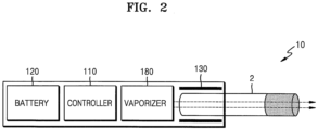
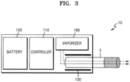
- FIGS. 1 through 3 are diagrams showing examples in which a cigarette is inserted into an aerosol generating apparatus.
- an aerosol generator 10 includes a battery 120, a controller 110, and a heater 130. Referring to FIG. 2 and FIG. 3 , the aerosol generator 10 further includes a vaporizer 180. Also, a cigarette 2 may be inserted into an inner space of the aerosol generator 10.
- FIGS. 2 and 3 show that the aerosol generator 10 includes the heater 130, but if necessary, the heater 130 may be omitted.
- FIG. 1 the battery 120, the controller 110, and the heater 130 are arranged in a row.
- FIG. 2 shows that the battery 120, the controller 110, the vaporizer 180, and the heater 130 are arranged in a row.
- FIG. 3 shows that the vaporizer 180 and the heater 130 are arranged in parallel with each other.
- an internal structure of the aerosol generator 10 is not limited to the examples shown in FIGS. 1 to 3 . That is, according to a design of the aerosol generator 10, arrangement of the battery 120, the controller 110, the heater 130, and the vaporizer 180 may be changed.
- the aerosol generator 10 When the cigarette 2 is inserted into the aerosol generator 10, the aerosol generator 10 operates the heater 130 and/or the vaporizer 180 to generate aerosol from the cigarette 2 and/or the vaporizer 180.
- the aerosol generated by the heater 130 and/or the vaporizer 180 may be transferred to a user via the cigarette 2.
- the aerosol generator 10 may heat the heater 130.
- the battery 120 supplies the electric power used to operate the aerosol generator 10.
- the battery 120 may supply power for heating the heater 130 or the vaporizer 180 and supply power for operating the controller 110.
- the battery 120 may supply power for operating a display, a sensor, a motor, and the like installed in the aerosol generator 10.
- the controller 110 controls the overall operation of the aerosol generator 10.
- the controller 110 may control operations of other elements included in the aerosol generator 10, as well as the battery 120, the heater 130, and the vaporizer 180. Also, the controller 110 may check the status of each component in the aerosol generator 10 to determine whether the aerosol generator 10 is in an operable state.
- the controller 110 includes at least one processor.
- a processor can be implemented as an array of a plurality of logic gates or can be implemented as a combination of a general-purpose microprocessor and a memory in which a program executable in the microprocessor is stored. It will be understood by one of ordinary skill in the art that the present disclosure may be implemented in other forms of hardware.
- the heater 130 may be heated by the electric power supplied from the battery 120.
- the heater 130 may be located outside the cigarette. Therefore, the heated heater 130 may raise the temperature of an aerosol generating material in the cigarette.
- the heater 130 may be an electro-resistive heater.
- the heater 130 includes an electrically conductive track, and the heater 130 may be heated as a current flows through the electrically conductive track.
- the heater 130 is not limited to the above example, and any type of heater may be used provided that the heater is heated to a desired temperature.
- the desired temperature may be set in advance on the aerosol generator 10, or may be set by a user.
- the heater 130 may include an induction heating type heater.
- the heater 130 may include an electrically conductive coil for heating the cigarette in an induction heating method, and the cigarette may include a susceptor that may be heated by the induction heating type heater.
- the heater 130 may include a tubular type heating element, a plate type heating element, a needle type heating element, or a rod type heating element, and may heat the inside or outside of the cigarette 2 according to the shape of the heating element.
- the plurality of heaters 13 may be arranged to be inserted into the cigarette 2 or on the outside of the cigarette 2. Also, some of the plurality of heaters 13 may be arranged to be inserted into the cigarette 2 and the other may be arranged on the outside of the cigarette 2.
- the shape of the heater 130 is not limited to the example shown in FIGS. 1 to 3 , but may be manufactured in various shapes.
- the vaporizer 180 may generate aerosol by heating a liquid composition and the generated aerosol may be delivered to the user after passing through the cigarette 2.
- the aerosol generated by the vaporizer 180 may move along an air flow passage of the aerosol generator 10, and the air flow passage may be configured for the aerosol generated by the vaporizer 180 to be delivered to the user through the cigarette.
- the vaporizer 180 may include a liquid storage unit, a liquid delivering unit, and a heating element, but is not limited thereto.
- the liquid storage unit, the liquid delivering unit, and the heating element may be included in the aerosol generator 10 as independent modules.
- the liquid storage may store a liquid composition.
- the liquid composition may be a liquid including a tobacco containing material including a volatile tobacco flavor component, or a liquid including a non-tobacco material.
- the liquid storage unit may be detachable from the vaporizer 180 or may be integrally manufactured with the vaporizer 180.
- the liquid composition may include water, solvents, ethanol, plant extracts, flavorings, flavoring agents, or vitamin mixtures.
- the flavoring may include, but is not limited to, menthol, peppermint, spearmint oil, various fruit flavoring ingredients, etc.
- the flavoring agent may include components that may provide the user with various flavors or tastes.
- Vitamin mixtures may be a mixture of at least one of vitamin A, vitamin B, vitamin C, and vitamin E, but are not limited thereto.
- the liquid composition may include an aerosol former such as glycerin and propylene glycol.
- the liquid delivery element may deliver the liquid composition of the liquid storage to the heating element.
- the liquid delivery element may be a wick such as cotton fiber, ceramic fiber, glass fiber, or porous ceramic, but is not limited thereto.
- the heating element is an element for heating the liquid composition delivered by the liquid delivering unit.
- the heating element may be a metal heating wire, a metal hot plate, a ceramic heater, or the like, but is not limited thereto.
- the heating element may include a conductive filament such as nichrome wire and may be positioned as being wound around the liquid delivery element. The heating element may be heated by a current supply and may transfer heat to the liquid composition in contact with the heating element, thereby heating the liquid composition. As a result, aerosol may be generated.
- the vaporizer 180 may be referred to as a cartomizer or an atomizer, but is not limited thereto.
- the aerosol generator 10 may further include universal elements, in addition to the battery 120, the controller 110, the heater 130, and the vaporizer 180.
- the aerosol generator 10 may include a display capable of outputting visual information and/or a motor for outputting tactile information.
- the aerosol generator 10 may include at least one sensor (a puff sensor, a temperature sensor, a cigarette insertion sensor, etc.)
- the aerosol generator 10 may be manufactured to have a structure, in which external air may be introduced or internal air may be discharged even in a state where the cigarette 2 is inserted.
- the aerosol generator 10 may configure a system with an additional cradle.
- the cradle may be used to charge the battery 120 of the aerosol generator 10.
- the heater 130 may be heated in a state in which the cradle and the aerosol generator 10 are coupled to each other.
- the cigarette 2 may be similar to a traditional combustive cigarette.
- the cigarette 2 may include a first portion containing an aerosol generating material and a second portion including a filter and the like.
- the second portion of the cigarette 2 may also include the aerosol generating material.
- an aerosol-generating material made in the form of granules or capsules may be inserted into the second portion.
- the aerosol generator 10 may be inserted into the aerosol generator 10 or the entire first portion and a portion of the second portion may be inserted into the aerosol generator 10.
- the user may puff aerosol while holding the second portion by the mouth of the user.
- the user may puff aerosol while holding the second portion by the mouth of the user.
- the aerosol is generated by as the outside air passes through the first portion, and the generated aerosol passes through the second portion and is delivered to a user's mouth.
- the outside air may be introduced through at least one air passage formed in the aerosol generator 10.
- the opening and closing of the air passage formed in the aerosol generator 10 and/or the size of the air passage may be adjusted by a user. Accordingly, the amount and quality of the aerosol may be adjusted by the user.
- the outside air may be introduced into the cigarette 2 through at least one hole formed in a surface of the cigarette 2.
- FIGS. 4 and 5 illustrate an example of a cigarette.
- the cigarette 2 includes a tobacco rod 21 and a filter rod 22.
- the first portion described above with reference to FIGS. 1 to 3 include the tobacco rod 21 and the second portion includes the filter rod 22.
- the filter rod 22 is shown as a single segment, but is not limited thereto.
- the filter rod 22 may include a plurality of segments.
- the filter rod 22 may include a first segment for cooling down the aerosol and a second segment for filtering a predetermined component included in the aerosol.
- the filter rod 22 may further include at least one segment performing another function.
- a diameter of the cigarette 2 may be in the range of 5 mm to 9 mm, and a length thereof may be about 48 mm, but embodiments are not limited thereto.
- a length of the tobacco rod 21 may be approximately 12 mm
- a length of the first segment of the filter rod 22 may be approximately 10 mm
- a length of the second segment of the filter rod 22 may be approximately 14 mm
- a length of the third segment of the filter rod 22 may be approximately 12mm.
- embodiments are not limited thereto.
- the cigarette 2 may be packaged by at least one wrapper 24.
- the wrapper 24 may include at least one hole through which the outside air is introduced or inside air is discharged.
- the cigarette 2 may be packaged by one wrapper 24.
- the cigarette 2 may be packaged by two or more wrappers 24.
- the tobacco rod 21 may be packaged via a first wrapper 241, and the filter rod 22 may be packaged by wrappers 242 to 244. And the entire cigarette 2 may be packaged by another wrapper 245.
- each segment may be packaged by separate wrapper 242, 243, and 244.
- the first wrapper 241 and the second wrapper 242 may be formed of general plug wrap paper.
- the first wrapper 241 and the second wrapper 242 may be porous wrapping paper or non-porous wrapping paper.
- the first wrapper 241 and the second wrapper 242 may be made of an oil-resistant paper sheet and an aluminum laminate packaging material.
- the third wrapper 243 may be made of a hard wrapping paper.
- a basis weight of the third wrapper 243 may be within a range of 88 g/m2 to 96 g/m2. Preferably, it may be within a range of 90 g/m2 to 94 g/m2.
- a total thickness of the third wrapper 243 may be within a range of 120 ⁇ m to 130 ⁇ m. Preferably, it may be 125 ⁇ m.
- the fourth wrapper 244 may be made of an oil-resistant hard wrapping paper.
- the basis weight of the fourth wrapper 244 may be within a range of about 88 g/m2 to about 96 g/m2. Preferably, it may be within a range of 90 g/m 2 to 94 g/m 2 .
- a total thickness of the fourth wrapper 244 may be within a range of 120 ⁇ m to 130 ⁇ m. Preferably, it may be 125 ⁇ m.
- the fifth wrapper 245 may be made of a sterilized paper (MFW).
- MFW refers to a paper specially manufactured to have enhanced tensile strength, water resistance, smoothness, and the like, compared to ordinary paper.
- the basis weight of the fifth wrapper 245 may be within a range of 57 g/m 2 to 63 g/m 2 . Preferably, it may be about 60 g/m 2 .
- the total thickness of the fifth wrapper 245 may be within a range of 64 ⁇ m to 70 ⁇ m. Preferably, it may be 67 ⁇ m.
- the tobacco rod 21 includes an aerosol generating material.
- the aerosol-generating material may include at least one of glycerin, propylene glycol, ethylene glycol, dipropylene glycol, diethylene glycol, triethylene glycol, tetraethylene glycol, and oleyl alcohol, but it is not limited thereto.
- the tobacco rod 21 may include other additive materials like a flavoring agent, a wetting agent, and/or an organic acid.
- a flavoring liquid such as menthol, humectant, etc. may be added to the tobacco rod 21 by being sprayed to the tobacco rod 21.
- the fifth wrapper 245 may prevent the cigarette 2 from being burned.
- the tobacco rod 210 is heated by the heater 13, there is a possibility that the cigarette 2 is burned.
- the temperature is raised to a temperature above the ignition point of any one of materials included in the tobacco rod 210, the cigarette 2 may be burned. Even in this case, since the fifth wrapper 245 include a non-combustible material, the burning of the cigarette 2 may be prevented.
- the fifth wrapper 245 may prevent the aerosol generating device 1 from being contaminated by substances formed by the cigarette 2.
- liquid substances may be formed in the cigarette 2.
- liquid materials e.g., moisture, etc.
- the fifth wrapper 245 wraps the cigarette 2, the liquid materials formed in the cigarette 2 may be prevented from being leaked out of the cigarette 2.
- the tobacco rod 21 may include an aerosol generating material.
- the aerosol generating material may include at least one of glycerin, propylene glycol, ethylene glycol, dipropylene glycol, diethylene glycol, triethylene glycol, tetraethylene glycol, and oleyl alcohol, but it is not limited thereto.
- the tobacco rod 21 may include other additives, such as flavors, a wetting agent, and/or organic acid.
- the tobacco rod 21 may include a flavored liquid, such as menthol or a moisturizer, which is injected to the tobacco rod 21.
- the tobacco rod 21 may be manufactured in various forms.
- the tobacco rod 21 may be fabricated as a sheet or strands.
- the tobacco rod 21 may be fabricated by tobacco leaves that are obtained by fine-cutting a tobacco sheet.
- the tobacco rod 21 may be surrounded by a heat conducting material.
- the heat-conducting material may be, but is not limited to, a metal foil such as aluminum foil.
- the heat conducting material surrounding the tobacco rod 21 may improve a thermal conductivity applied to the tobacco rod by evenly dispersing the heat transferred to the tobacco rod 21, and thereby improving tobacco taste.
- the heat conducting material surrounding the tobacco rod 21 may function as a susceptor that is heated by an inducting heating type heater.
- the tobacco rod 21 may further include a susceptor, in addition to the heat conducting material surrounding the outside thereof.
- the filter rod 22 may be a cellulose acetate filter.
- the filter rod 22 is not limited to a particular shape.
- the filter rod 22 may be a cylinder type rod or a tube type rod including a cavity therein.
- the filter rod 22 may be a recess type rod.
- the filter rod 22 includes a plurality of segments, at least one of the plurality of segments may have a different shape from the others.
- the first segment of the filter rod 22 may be made of cellulose acetate.
- the first segment may be a tube-shaped structure containing a hollow therein.
- the first segment may prevent an internal material of the tobacco rod 21 from being pushed back when the heater 13 is inserted into the tobacco rod 210 and may also provide a cooling effect to the aerosol.
- a diameter of the hollow included in the first segment may be an appropriate diameter within a range of 2 mm to 4.5 mm but is not limited thereto.
- a length of the first filter segment may be appropriately selected within a range of 4 mm to 30 mm, but is not limited thereto.
- the length of the first filter segment may be 10 mm, but is not limited thereto.
- Hardness of the first filter segment may be adjusted by adjusting content of a plasticizer at the time of manufacturing the first filter segment.
- the first filter segment may be made by inserting a structure such as a film or a tube of the same material or different materials therein (for example, in a hollow).
- the second segment of the filter rod 22 cools an aerosol generated by the heater 13 heating the tobacco rod 21. As such, a user may inhale the aerosol cooled to an appropriate temperature.
- a length or a diameter of the second segment may be variously determined according to a shape of the cigarette 2.
- a length of the second segment may be appropriately selected within a range of 7 mm to 20 mm.
- the length of the second segment may be 14 mm, but is not limited thereto.
- the second segment may be made by weaving polymer fiber.
- the fiber made of a polymer may be coated with a flavored liquid.
- the second segment may also be made by weaving fiber coated with a flavored liquid and fiber made of a polymer.
- the cooling structure 222 may be formed of a crimped polymer sheet.
- the polymer may be made of a material selected from a group consisting of polyethylene (PE), polypropylene (PP), polyvinyl chloride (PVC), polyethylene terephthalate (PET), polylactic acid (PLA), cellulose acetate (CA), and aluminum foil.
- PE polyethylene
- PP polypropylene
- PVC polyvinyl chloride
- PET polyethylene terephthalate
- PLA polylactic acid
- CA cellulose acetate
- aluminum foil aluminum foil
- the second segment is formed of woven polymer fiber or a crimped polymer sheet
- the second segment may include single or multiple channels extending in a longitudinal direction.
- the channel indicates a passage through which gas (for example, air or aerosol) passes.
- the second segment made of a crimped polymer sheet may be formed of a material having a thickness between approximately 5 ⁇ m and approximately 300 ⁇ m, for example between approximately 10 ⁇ m and approximately 250 ⁇ m.
- a total surface area of the second segment may be between approximately 300 mm 2 /mm and approximately 1000 mm 2 /mm.
- an aerosol cooling element may be formed of a material having a specific surface area between approximately 10 mm 2 /mg and approximately 100 mm 2 /mg.
- the second segment may include a thread containing a volatile flavor component.
- the volatile flavor component may be menthol, but is not limited thereto.
- the thread may be filled with the sufficient amount of menthol to provide menthol of 1.5 mg or more to the second segment.
- the third segment of the filter rod 22 may be a cellulose acetate filter.
- a length of the third segment may be appropriately selected within a range of 4 mm to 20 mm.
- the length of the third segment may be approximately 12 mm, but is not limited thereto.
- a flavored liquid may be sprayed to the third segment such that the third segment provides flavor.
- separate fiber coated with a flavored liquid may be inserted into the third segment.
- the aerosol generated in the tobacco rod 21 is cooled while passing through the second segment, and the cooled aerosol is delivered to a user through the third segment. Therefore, when a flavoring element is added to the third segment, persistence of flavor delivered to a user may be enhanced.
- the filter rod 22 may include at least one capsule 23.
- the capsule 23 may generate flavor or may generate aerosol.
- the capsule 23 may have a structure, in which a liquid containing a flavoring material is wrapped with a film.
- the capsule 23 may have a circular or cylindrical shape, but is not limited thereto.
- the cigarette 3 additionally includes a front-end plug 33.
- the front-end plug 33 may be located on a side of the tobacco rod 31, the side not facing the filter rod 32.
- the front-end plug 33 may prevent the tobacco rod 31 from escaping to the outside and may prevent a liquefied aerosol from flowing from the tobacco rod 31 into an aerosol generating device (1 of FIGS. 1 to 3 ) during smoking.
- the filter rod 32 may include a first segment 321 and a second segment 322.
- the first segment 321 may correspond to the first segment of the filter rod 22 of FIG. 4
- the second segment 322 may correspond to the third segment of the filter rod 22 of FIG. 4 .
- the diameter and the total length of the cigarette 3 may correspond to the diameter and the total length of the cigarette 2 of FIG. 4 .
- the length of the front end plug 33 is about 7 mm
- the length of the cigarette rod 31 is about 15 mm
- the length of the first segment 321 is about 12 mm
- the length of the second segment 322 is about 14 mm.
- embodiments are not limited thereto.
- the cigarette 3 may be wrapped by at least one wrapper 35. At least one hole through which outside air flows in or inside gas flows out may be formed in the wrapper 35.
- the front-end plug 33 may be wrapped by a first wrapper 241 351
- the tobacco rod 31 may be wrapped by a second wrapper 352
- the first segment 321 may be wrapped by a third wrapper 353
- the second segment 322 may be wrapped by a fourth wrapper 354.
- the entire cigarette 3 may be re-wrapped by a fifth wrapper 355.
- At least one perforation 36 may be formed in the fifth wrapper 355.
- the perforation 36 may be formed in a region surrounding the tobacco rod 31, but is not limited thereto.
- the perforation 36 may serve to transfer heat generated by the heater 130 shown in FIGS. 2 and 3 into the tobacco rod 31.
- the second segment 322 may include at least one capsule 34.
- the capsule 34 may serve to generate a flavor or serve to generate an aerosol.
- the capsule 34 may have a structure in which a liquid containing perfume is wrapped in a film.
- the capsule 34 may have a spherical or cylindrical shape, but is not limited thereto.
- the first wrapper 351 may be a metal foil such as aluminum foil bonded to a general filter wrapping paper.
- the total thickness of the first wrapper 351 may be in the range of 45 um to 55 um, and preferably it may be 50.3 um.
- the thickness of the metal foil of the first wrapper 351 may be in the range of 6um to 7um, and preferably it may be 6.3 um.
- the basis weight of the first wrapper 351 may be in the range of 50 g/m2 to 55 g/m2, and preferably it may be 53 g/m2.
- the second wrapper 352 and the third wrapper 353 may be made of a general filter wrapping paper.
- the second wrapper 352 and the third wrapper 353 may be porous wrapping paper or non-porous wrapping paper.
- the porosity of the second wrapper 352 may be 35,000 CU, but is not limited thereto.
- the thickness of the second wrapper 352 may be in the range of 70 um to 80 um, and preferably it may be 78 um.
- the basis weight of the second wrapper 352 may be in the range of 20 g/m2 to 25 g/m2, and preferably it may be 23.5 g/m2.
- the porosity of the third wrapper 353 may be 24,000 CU, but is not limited thereto.
- the thickness of the third wrapper 353 may be in the range of 60 um to 70 um, and preferably it may be 68 um.
- the basis weight of the third wrapper 353 may be in the range of 20 g/m2 to 25 g/m2, and preferably it may be 21 g/m2.
- the fourth wrapper 354 may be made of a polylactic acid (PLA) laminated paper.
- the polylactic acid(PLA) laminated paper may be a three-layer paper including a paper layer, a polylactic acid(PLA) layer and a paper layer.
- the thickness of the fourth wrapper 354 may be in the range of 100 um to 120 um, and preferably it may be 1 10um.
- the basis weight of the fourth wrapper 354 may be in the range of 80 g/m2 to 100 g/m2, and preferably it may be 88 g/m2.
- the fifth wrapper 355 may be made of a sterile paper.
- the sterile paper refers to a paper specially manufactured to improve tensile strength, water resistance, smoothness, and the like, compared to ordinary paper.
- the basis weight of the fifth wrapper 355 may be in the range of 57 g/m2 to 63 g/m2, and preferably it may be 60 g/m2.
- the thickness of the fifth wrapper 355 may be in the range of 64 um to 70 um, and preferably it may be 67 um.
- the fifth wrapper 355 may have a predetermined material added therein.
- silicon may be an example of the predetermined material, but is not limited thereto.
- silicone has characteristics such as heat resistance, oxidation resistance, resistance to various chemicals, water repellency, and electrical insulation. However, even if it is not silicon, any material having the above-described properties may be applied (or coated) to the fifth wrapper 355 without limitation.
- the front-end plug 33 may be made of cellulose acetate.
- the front-plug 33 may be manufactured by adding a plasticizer (e.g., triacetin) to cellulose acetate tow.
- the mono denier of the filaments constituting the cellulose acetate tow may be in the range of 1.0 to 10.0, preferably in the range of 4.0 to 6.0. More preferably, the mono denier of the filament of the front-end plug 33 may be 5.0.
- the cross-section of the filament constituting the front-end plug 33 may be Y-shaped.
- the total denier of the front-end plug 33 may be in the range of 20,000 to 30,000, preferably in the range of 25,000 to 30,000. More preferably, the total denier of the front-end plug 33 may be 28,000.
- the front- end plug 33 may include at least one channel, and the cross-sectional shape of the channel may be manufactured in various shapes
- the cigarette rod 31 may correspond to the cigarette rod 21 described above referring to FIG. 4 . Therefore, hereinafter, detailed description of the cigarette rod 31 is omitted.
- the first segment 321 may be made of cellulose acetate.
- the first segment may be a tube-shaped structure containing a hollow therein.
- the first segment 321 may be manufactured by adding a plasticizer (e.g., triacetin) to cellulose acetate tow.
- a plasticizer e.g., triacetin
- the mono denier and total denier of the first segment 321 may be the same as the mono and total denier of the front-end plug 33.
- the second segment 322 may be made of cellulose acetate.
- the mono denier of the filaments constituting the second segment 322 may be in the range of 1.0 to 10.0, and preferably may be included in the range of 8.0 to 10.0. More preferably, the mono denier of the filament of the second segment 322 may be 9.0.
- the cross-section of the filament of the second segment 322 may be Y-shaped.
- the total denier of the second segment 322 may be included in the range of 20,000 to 30,000, and preferably it may be 25,000.
- FIG. 6 is a diagram schematically showing a block diagram of an example of an aerosol-generating device according to an embodiment.
- the aerosol-generating device may include a controller 110, a battery 120, a heater 130, a pulse width modulation processing unit 140, a display 150, a motor 160, and a storage device 170.
- the controller 110 controls operations of the battery 120, the heater 130, the pulse width modulation processing unit 140, the display 150, the motor 160, and the storage devices 170 included in the aerosol-generating device.
- the controller 110 may further include an input receiving unit (not shown) that receives a user's button input or touch input, and a communication unit (not shown) capable of communicating with an external communication device such as a user terminal.
- the controller 110 may further include a module for performing proportional integral differential control (PID) on the heater 130.
- PID proportional integral differential control
- the battery 120 supplies power to the heater 130, and an amount of power supplied to the heater 130 may be adjusted by the controller 110.
- the heater 130 generates heat by specific resistance when a current is applied.
- aerosols may be generated.
- the pulse width modulation processing unit 140 allows the controller 110 to control the power supplied to the heater 130 by transmitting pulse width modulation (PWM) signals to the heater 130.
- PWM pulse width modulation
- the pulse width modulation processing unit 140 may be implemented to be included in the controller 110.
- the display 150 visually outputs various alarm messages generated by the aerosol-generating device 10 so that a user using the aerosol-generating device 10 may check the alarm messages.
- the user may check a battery power shortage message or a heater overheat warning message output to the display 150, and then may take appropriate measures before an operation of the aerosol-generating device 10 stops or the aerosol-generating device 10 is damaged.
- the motor 160 is driven by the controller 110 so that the user may recognize that the aerosol-generating device 10 is ready for use through tactile sense.
- the storage device 170 stores various pieces of information to provide a consistent flavor to the user who uses the aerosol-generating device 10 while appropriately controlling power supplied to the heater 130 by the controller110.
- information stored in the storage device 170 includes a temperature profile which is referenced by the controller 110 to appropriately control the temperature of the heater over time, a control reference ratio to be described later, and a comparison control value.
- the storage device 170 may store the temperature profile, the control reference ratio, and the comparison control value in advance, and then transmit the information to the controller 110 at the request of the controller 110.
- the storage device 170 may not only be configured as a non-volatile memory, such as a flash memory, but also may be configured as a volatile memory that temporarily stores data only when power is supplied in order to secure a faster data input/output (I/O) speed.
- a non-volatile memory such as a flash memory
- volatile memory that temporarily stores data only when power is supplied in order to secure a faster data input/output (I/O) speed.
- the controller 110, the pulse width modulation processing unit 140, the display 150, the storage device 170 and the vaporizer may correspond to at least one processor or may include at least one processor, according to an embodiment the present invention Accordingly, the controller 110, the pulse width modulation processing unit 140, the display 150, the storage device 170 and the vaporizer may be driven in a form included in other hardware device such as a microprocessor or general purpose computer system.
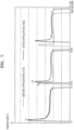
- FIG. 7 is a graph for explaining a method for controlling a temperature of a heater of an aerosol-generating device.
- the heater 130 of the aerosol-generating device is heated in a pattern in which the temperature of the heater 130 rises to a maximum T1, then falls and maintains a constant temperature.
- the heater 130 is supplied with the power of the battery 120 under control of the controller 110 to represent the temperature curve as shown in FIG. 7 .
- a horizontal axis represents time (second), and a vertical axis represents Celsius temperature.
- a solid line 730 shows a graph of a temperature change of the heater 130 when proportional integral differential (PID) control is performed on power supplied to the heater 130 by applying the integral control weight according to the present invention.
- PID proportional integral differential
- the controller 110 when the controller 110 supplies power to the heater 130 from the time 11, the temperature of the heater 130 rises to a preheating target temperature T1. Then, the temperature of the heater 130 rapidly decreases to and is maintained at a certain temperature. The user may enjoy smoking through the aerosol-generating device after the heater 130 reaches the preheating target temperature.
- the controller 110 may output to the user through the display 150 information indicating that preheating of the heater 130 is completed and the user may start smoking. The user may inhale the aerosol through the aerosol-generating device for a certain period of time during which the temperature of the heater 130 is maintained after the notification is output.
- a time interval between t 1 and t 2 is referred to as a first smoking section
- a time interval between t 3 and t 5 is referred to as a second smoking section
- a time interval between t 4 and t 6 is referred to as a third smoking section.
- Each smoking section contains at least one puff.
- the first, second, and third smoking sections are for distinguishing each smoking section, and the smoking does not necessarily progresses in this order.
- the temperature of the heater 130 rapidly decreases at t 2 by user's smoking. If the user smokes again through the aerosol-generating device within a certain time period, the heater 130 is heated again in the second smoking section.
- the controller 110 controls the power supplied to the heater 130 through the proportional integral differential (PID) control in a state the temperature of the heater 130 is not sufficiently lowered, the preheating target temperature of the heater 130 is lowered to T 2 of the second smoking section, not T 1 .
- PID proportional integral differential
- a holding temperature of the heater 130 maintained until the time t5 after reaching the preheating target temperature T 2 is also lower than a holding temperature of the first smoking section.
- the preheating target temperature and holding temperature in the second smoking section are lower than the preheating target temperature and holding temperature in the first smoking section, respectively, the heat energy is not sufficiently transferred to the aerosol-generating substrate, and thus, it is difficult to secure a sufficient amount of atomization.
- the controller 110 controls the power supplied to the heater 130 through the proportional integral differential control in a state the temperature of the heater 130 is not sufficiently lowered.
- the controller 130 corrects an integral control gain value based on an integral proportional weight, such that the temperature of the heater 130 in the third smoking section may increase to a preheating target temperature T 3 and a holding temperature which is maintained after the preheating target temperature T 3 is also higher than a holding temperature of the second smoking section.
- the controller 110 includes a timer to measure an interval between time t 2 and time t 4 . The controller 110 determines that there is a continuous smoking by the user if the measured time interval is within a preset range.
- the controller 110 included in the aerosol-generating device controls the power supplied to the heater based on the integral control weight determined depending on an initial temperature of the heater through the proportional integral differential (PID) control.
- PID proportional integral differential
- Equation 1 shows an example of a control function used when the controller 110 controls the power supplied to the heater through a general proportional integral differential method. Since the general proportional integral differential control method is a known technique, description of each variable is omitted. The controller 110 may obtain an appropriate proportional control gain value, integral control gain value, and differential control gain value through trial and error by a mathematical, experimental, or empirical method. However, according to the proportional integral differential control method as described above, it is not possible to prevent a decrease in the aerosol atomization amount occurring when a user continuously smokes.
- c * t K p ⁇ e t + K I ⁇ ⁇ 0 t e ⁇ d ⁇ + C I + K D ⁇ de dt
- Equation 2 shows an example of a control function used when the controller 110 controls power supplied to the heater according to the present invention.
- C I means the integral control weight.
- the controller 110 may directly calculate the integral control weight based on the initial temperature of the heater 130, or obtain the integral control weight by referring to a weight table stored in the storage device 170.
- controller 110 determines the integral control weight in the present invention.
- the controller 110 may calculate the integral control weight based on the initial temperature of the heater after a certain period of time has elapsed, after the heater reaches the preheating target temperature. According to this exemplary embodiment, when the temperature of the heater 130 decreases after a certain period of time has elapsed after the heater 130 reaches the preheating target temperature, the controller 110 regards the lowered temperature as the initial temperature of the heater 130 and calculates the integral control weight based thereon. Referring to FIG.
- the controller 110 considers that a user's primary smoking is over at t 2 , and calculates the integral control weight by using the temperature of the heater 130 at a time point after t 2 as an initial temperature.
- the controller 110 may calculate an integral control weight based on an integral control gain value when the heater 130 is preheated and reaches 50 °C or may calculate an integral control weight based on an integral control gain value when the heater 130 reaches a maximum temperature.
- C I a ⁇ K Imax ⁇ K 50 T max ⁇ 50 ⁇ T Initial + C r
- Equation 3 is an example of the equation used by the controller 110 to calculate the integral control weight based on the initial temperature of the heater 130.
- K Imax is an integral control gain value when the temperature of the heater 130 is the highest temperature in the immediately preceding smoking section
- K 50 is an integral control gain value when the temperature of the heater 130 is 50 °C in the immediately preceding smoking section
- T max is the maximum temperature of the heater 130 in the immediately preceding smoking section
- T Initial is the initial temperature of the heater 130
- a is a proportional constant greater than 1 and less than 3
- C r is an arbitrary constant.
- the controller 110 may calculate the integral control weight based on Equation 3, and the values necessary to calculate the integral control weight may be collected and stored in the storage device 170 when the heater 130 is heated in the immediately preceding smoking section.
- the controller 110 may determine the integral control weight by referring to a table in which the integral control weight values are respectively associated with initial temperatures of the heater 130.
- Table 1 Initial temperature range of heater Integral control weight (Ci) Less than 50 degrees 0 50 ⁇ 100 20 100 ⁇ 150 38 150 ⁇ 200 58 200 ⁇ 250 70
- Table 1 shows an example of a table stored in the storage device 170. According to Table 1, if an initial temperature of the heater is between 50 and 100 degrees, the controller 110 may determine an integral control weight as 20. If an initial temperature of the heater is between 150 and 200 degrees, the controller 110 may determine an integral control weight as 58. Table 1 is a table that the controller 110 refers to when the aerosol-generating device is continuously used. In the case where the aerosol-generating device is not continuously used, the controller 110 does not refer to Table 1 and does not determine the integral control weight. The integral control weight corresponding to the initial temperature range of the heater in Table 1 is only an example, and the detailed values may vary according to embodiments. FIG. 8 is a flowchart illustrating an example of a method for controlling power of a heater of an aerosol-generating device according to the present invention.
- FIG. 8 Since the method according to FIG. 8 may be implemented by the aerosol-generating device according to FIG. 6 , it will be described below with reference to FIG. 6 , and descriptions overlapping with those described in FIG. 6 will be omitted.
- step S810 a first smoking process through the aerosol-generating device is terminated by a user.
- the controller 110 included in the aerosol-generating device may store the integral control gain value, which is used to control the temperature of the heater in the first smoking process, in the storage device 170.
- step S820 the controller 110 identifies the temperature of the heater of the aerosol-generating device to start a second smoking process.
- the controller 110 measures the time interval between the end of the first smoking process and the start of the second smoking process through a built-in timer. If the measured time interval is within a certain period of time, the controller 110 determines that a continuous smoking has occurred, and controls the power supplied to the heater 130 according to the present invention.
- step S830 the controller 110 determines an integral control gain value for performing integral control as part of proportional integral differential control based on the initial temperature of the heater.
- the controller 110 retrieves the integral control weight for determining the integral control gain value.
- the integral control weight retrieved in step S830 may be a value stored as a table in the storage device 170 or a value calculated by the controller 110 according to Equation 3 as the initial temperature of the heater.
- step S840 the controller 110 supplies power required to increase the temperature of the heater 130 to a preheating target temperature.
- step S850 the controller 110 determines whether the heater 130 has reached the preheating target temperature.
- step S860 if the heater has reached the preheating target temperature, the controller 110 controls the temperature of the heater 130 to be maintained constant by performing integral control based on the integral control weight retrieved in step S830.
- step S860 which is a step of maintaining the temperature of the heater 130 in accordance with the integral control weight
- the integral term corrects the steady-state error in the proportional integral differential control. This is based on the tendency that the integral proportional gain is determined after the proportional control gain is first determined.
- the temperature of the heater 130 is heated to a sufficiently high preheating target temperature (for example, T 3 in FIG. 7 ) and maintained constant. As such, sufficient thermal energy may be transferred to the aerosol-generating substrate, and the user may have a consistent smoking feeling without a lack of atomization over the course of continuous smoking.
- the above-described embodiment according to the present invention may be implemented in a form of a computer program that may be executed through various components on a computer, and such a computer program may be recorded on a computer-readable medium.
- the medium may include a hardware device specifically configured to store and execute program instructions, such as a magnetic media including hard disks, floppy disks and magnetic tapes, an optical recording media including CD-ROMs and DVDs, a magneto-optical media including floptical disks, and a memory including ROM, RAM and flash memory.
- the computer program may be specially designed and configured for the present invention, or may be known and available to those skilled in the computer software field.
- Examples of computer programs may include not only machine language codes generated by a compiler, but also high-level language codes that may be executed by a computer using an interpreter or the like.
- connection or connection members of the lines between the components shown in the drawings are illustratively showing functional connections and/or physical or circuit connections, and in a real device, it may be represented as an alternative or additional various functional connections, physical connections, or circuit connections.
- it may not be a necessary component for application of the present invention.
- One embodiment of the present invention may be used to manufacture a next-generation electronic cigarette with improved performance than the prior art.
Landscapes
- Engineering & Computer Science (AREA)
- Physics & Mathematics (AREA)
- General Physics & Mathematics (AREA)
- Automation & Control Theory (AREA)
- Power Engineering (AREA)
- Catching Or Destruction (AREA)
- Disinfection, Sterilisation Or Deodorisation Of Air (AREA)
- Control Of Resistance Heating (AREA)
Claims (15)
- Aerosolerzeugende Vorrichtung, die Folgendes umfasst:eine Heizeinrichtung (130), die konfiguriert ist, ein aerosolerzeugendes Substrat zu erhitzen; undeine Steuereinheit (110), die konfiguriert ist, Leistung, die der Heizeinrichtung (130) zugeführt wird, auf der Basis einer Steuergewichtung, die entsprechend einer Anfangstemperatur der Heizeinrichtung (130) ermittelt wird, durch ein Proportional-Integral-Differenzial-Verfahren (PID-Verfahren) zu steuern,dadurch gekennzeichnet, dass die Steuergewichtung eine integrale Steuergewichtung der PID-Steuereinheit ist, undwobei ein Zeitintervall zwischen t1 und t2 ein erster Rauchabschnitt ist und ein Zeitintervall zwischen t4 und t6 ein zweiter Rauchabschnitt ist, undwobei die Steuereinheit (110) konfiguriert ist, ein Zeitintervall zwischen t2 und t4 zu messen und wobei die Steuereinheit (110) konfiguriert ist, festzustellen, dass durch den Benutzer ein kontinuierliches Rauchen erfolgt, wenn das gemessene Zeitintervall in einem zuvor festgelegten Bereich liegt.
- Aerosolerzeugende Vorrichtung nach Anspruch 1, wobei die Steuereinheit (110) konfiguriert ist, die integrale Steuergewichtung auf der Basis der Anfangstemperatur der Heizeinrichtung (130) zu berechnen, die gemessen wird, nachdem eine zuvor festgelegte Zeit verstrichen ist, seitdem eine Temperatur der Heizeinrichtung (130) eine zuvor festgelegte Vorheiztemperatur erreicht hat, und/oder wobei die Steuereinheit (110) konfiguriert ist, die integrale Steuergewichtung auf der Basis eines integralen Steuerverstärkungswerts zu berechnen, der verwendet wird, wenn die Heizeinrichtung auf 50 °C vorgeheizt ist.
- Aerosolerzeugende Vorrichtung nach Anspruch 1, wobei die Steuereinheit (110) konfiguriert ist, die integrale Steuergewichtung auf der Basis einer Höchsttemperatur zu berechnen, die die Heizeinrichtung (130) in einem ersten Vorheizvorgang erreicht hat, und/oder wobei die Steuereinheit (110) konfiguriert ist, die integrale Steuergewichtung auf der Basis eines höchsten integralen Steuerverstärkungswerts in einem ersten Vorheizvorgang zu berechnen, indem auf integrale Steuerverstärkungswerte Bezug genommen wird, die im ersten Vorheizvorgang der Heizeinrichtung verwendet werden.
- Aerosolerzeugende Vorrichtung nach Anspruch 1, wobei die Steuereinheit (110) konfiguriert ist, die integrale Steuergewichtung zu ermitteln, indem auf eine Tabelle Bezug genommen wird, in der integrale Steuergewichtungen jeweils Anfangstemperaturen der Heizeinrichtung (130) zugeordnet sind.
- Aerosolerzeugende Vorrichtung nach Anspruch 1, wobei die integrale Steuergewichtung größer oder gleich 20 ist und/oder die integrale Steuergewichtung kleiner oder gleich 70 ist und/oder die integrale Steuergewichtung in einem Bereich von 20 bis 70 liegt.
- Verfahren zum Steuern der Leistung, die einer Heizeinrichtung (130) einer aerosolerzeugenden Vorrichtung zugeführt wird, wobei das Verfahren die folgenden Schritte umfasst:Ermitteln einer Anfangstemperatur einer Heizeinrichtung (130) einer aerosolerzeugenden Vorrichtung;Ermitteln einer Steuergewichtung zum Steuern in einer Proportional-Integral-Differenzialsteuereinheit auf der Basis der ermittelten Anfangstemperatur der Heizeinrichtung (130); undBeibehalten einer Temperatur der Heizeinrichtung auf der Basis der ermittelten Steuergewichtung, nachdem die Temperatur der Heizeinrichtung (130) eine Vorheiztemperatur erreicht hat,dadurch gekennzeichnet, dass die Steuergewichtung eine integrale Steuergewichtung für eine integrale Steuereinheit der PID-Steuereinheit ist, undwobei ein Zeitintervall zwischen t1 und t2 ein erster Rauchabschnitt ist und ein Zeitintervall zwischen t4 und t6 ein zweiter Rauchabschnitt ist, undwobei das Verfahren ferner die folgenden Schritte umfasst:Messen eines Zeitintervalls zwischen t2 und t4, undFeststellen, dass durch den Benutzer ein kontinuierliches Rauchen erfolgt, falls das gemessene Zeitintervall in einem zuvor festgelegten Bereich liegt.
- Verfahren nach Anspruch 6, wobei das Ermitteln der integralen Steuergewichtung das Berechnen der integralen Steuergewichtung auf der Basis der Anfangstemperatur der Heizeinrichtung (130) umfasst, die gemessen wird, nachdem eine bestimmte Zeitspanne verstrichen ist, seitdem die Temperatur der Heizeinrichtung eine zuvor festgelegte Vorheiztemperatur erreicht hat.
- Verfahren nach Anspruch 6, wobei das Ermitteln der integralen Steuergewichtung das Berechnen der integralen Steuergewichtung auf der Basis eines integralen Steuerverstärkungswerts umfasst, der verwendet wird, wenn die Heizeinrichtung auf 50 °C vorgeheizt ist.
- Verfahren nach Anspruch 6, wobei das Ermitteln der integralen Steuergewichtung das Berechnen der integralen Steuergewichtung auf der Basis einer Höchsttemperatur umfasst, die die Heizeinrichtung in einem ersten Vorheizvorgang erreicht hat.
- Verfahren nach Anspruch 6, wobei das Ermitteln der integralen Steuergewichtung das Berechnen der integralen Steuergewichtung auf der Basis eines höchsten integralen Steuerverstärkungswerts in einem ersten Vorheizvorgang umfasst, indem auf integrale Steuerverstärkungswerte Bezug genommen wird, die im ersten Vorheizvorgang verwendet werden.
- Verfahren nach Anspruch 6, wobei das Ermitteln der integralen Steuergewichtung das Ermitteln der integralen Steuergewichtung durch Bezugnahme auf eine Tabelle, in der integrale Steuergewichtungen jeweils Anfangstemperaturen der Heizeinrichtung zugeordnet sind, umfasst.
- Verfahren nach Anspruch 6, wobei die integrale Steuergewichtung größer oder gleich 20 ist.
- Verfahren nach Anspruch 10, wobei die integrale Steuergewichtung kleiner oder gleich 70 ist.
- Verfahren nach Anspruch 10, wobei die integrale Steuergewichtung in einem Bereich von 20 bis 70 liegt.
- Computerlesbares Speichermedium, das ein Programm zum Ausführen des Verfahrens nach einem der Ansprüche 6 bis 14 speichert.
Applications Claiming Priority (2)
| Application Number | Priority Date | Filing Date | Title |
|---|---|---|---|
| KR1020180141972A KR102317838B1 (ko) | 2018-11-16 | 2018-11-16 | 에어로졸 생성장치의 히터의 전력을 제어하는 방법 및 그 에어로졸 생성장치 |
| PCT/KR2019/013997 WO2020101203A1 (ko) | 2018-11-16 | 2019-10-23 | 에어로졸 생성장치의 히터의 전력을 제어하는 방법 및 그 에어로졸 생성장치 |
Publications (3)
| Publication Number | Publication Date |
|---|---|
| EP3818873A1 EP3818873A1 (de) | 2021-05-12 |
| EP3818873A4 EP3818873A4 (de) | 2022-03-23 |
| EP3818873B1 true EP3818873B1 (de) | 2023-11-29 |
Family
ID=70730859
Family Applications (1)
| Application Number | Title | Priority Date | Filing Date |
|---|---|---|---|
| EP19885489.5A Active EP3818873B1 (de) | 2018-11-16 | 2019-10-23 | Verfahren zur steuerung der elektrischen leistung eines heizers eines aerosolgenerators sowie aerosolgenerator |
Country Status (8)
| Country | Link |
|---|---|
| US (1) | US11992063B2 (de) |
| EP (1) | EP3818873B1 (de) |
| JP (1) | JP7036499B2 (de) |
| KR (1) | KR102317838B1 (de) |
| CN (1) | CN112203537B (de) |
| ES (1) | ES2975454T3 (de) |
| PL (1) | PL3818873T3 (de) |
| WO (1) | WO2020101203A1 (de) |
Families Citing this family (30)
| Publication number | Priority date | Publication date | Assignee | Title |
|---|---|---|---|---|
| KR102317838B1 (ko) * | 2018-11-16 | 2021-10-26 | 주식회사 케이티앤지 | 에어로졸 생성장치의 히터의 전력을 제어하는 방법 및 그 에어로졸 생성장치 |
| GB201903290D0 (en) | 2019-03-11 | 2019-04-24 | Nicoventures Trading Ltd | An article for use in a non-combustible aerosol provision system |
| GB201908353D0 (en) * | 2019-06-11 | 2019-07-24 | Nicoventures Trading Ltd | A mouthpiece and an article for use in an aerosol provision system |
| GB201908356D0 (en) | 2019-06-11 | 2019-07-24 | Nicoventures Trading Ltd | An article for use in a non-combustible aerosol provision system |
| GB202002714D0 (en) * | 2020-02-26 | 2020-04-08 | Nicoventures Trading Ltd | Apparatus for generating an aerosol |
| KR20230095875A (ko) * | 2020-06-10 | 2023-06-29 | 이스모킹 인스티튜드 에스피. 지 오.오. | 에어로졸 제공 디바이스 |
| KR102455535B1 (ko) * | 2020-06-16 | 2022-10-17 | 주식회사 케이티앤지 | 에어로졸 생성 장치 및 그 동작 방법 |
| CN114502021B (zh) * | 2020-09-07 | 2024-02-23 | 韩国烟草人参公社 | 气溶胶生成装置 |
| JP7324360B2 (ja) * | 2020-09-07 | 2023-08-09 | ケーティー アンド ジー コーポレイション | エアロゾル生成装置 |
| US11789476B2 (en) | 2021-01-18 | 2023-10-17 | Altria Client Services Llc | Heat-not-burn (HNB) aerosol-generating devices including intra-draw heater control, and methods of controlling a heater |
| US12520880B2 (en) | 2021-01-18 | 2026-01-13 | Altria Client Services Llc | Heat-not-burn (HNB) aerosol-generating devices including energy based heater control, and methods of controlling a heater |
| KR20230154460A (ko) * | 2021-03-31 | 2023-11-08 | 니뽄 다바코 산교 가부시키가이샤 | 비연소 가열식 향미 흡인 물품 및 비연소 가열식 향미 흡인 제품 |
| CN113245093B (zh) * | 2021-04-15 | 2022-03-29 | 深圳美众联科技有限公司 | 雾化装置的控制方法、雾化装置、计算机设备和存储介质 |
| EP4358773A1 (de) * | 2021-06-24 | 2024-05-01 | Philip Morris Products S.A. | Aerosolerzeugungsvorrichtung mit steuerschaltung für ein heizelement |
| KR102637145B1 (ko) * | 2021-06-29 | 2024-02-16 | 주식회사 케이티앤지 | 에어로졸 생성 장치 및 에어로졸 생성 장치의 히터온도 제어 방법 |
| KR102644193B1 (ko) * | 2021-07-28 | 2024-03-06 | 주식회사 케이티앤지 | 에어로졸 생성 물품에 대한 예열 동작을 제어하는 에어로졸 생성 장치 및 그의 동작 방법 |
| KR102696395B1 (ko) * | 2021-08-27 | 2024-08-20 | 주식회사 케이티앤지 | 에어로졸 생성 장치 및 이의 제어 방법 |
| KR102792437B1 (ko) * | 2021-10-29 | 2025-05-15 | 주식회사 케이티앤지 | 에어로졸 생성장치 |
| WO2023075505A1 (en) * | 2021-10-29 | 2023-05-04 | Kt&G Corporation | Aerosol-generating device |
| WO2023073931A1 (ja) * | 2021-10-29 | 2023-05-04 | 日本たばこ産業株式会社 | 吸引装置、基材、及び制御方法 |
| KR102727667B1 (ko) * | 2022-02-11 | 2024-11-07 | 주식회사 케이티앤지 | 에어로졸 생성 장치 및 이의 제어 방법 |
| KR102817087B1 (ko) * | 2022-02-11 | 2025-06-05 | 주식회사 케이티앤지 | 에어로졸 생성 장치 및 이의 제어 방법 |
| WO2023181282A1 (ja) | 2022-03-24 | 2023-09-28 | 日本たばこ産業株式会社 | エアロゾル生成システム、制御方法、及びプログラム |
| KR20240144360A (ko) | 2022-03-24 | 2024-10-02 | 니뽄 다바코 산교 가부시키가이샤 | 에어로졸 생성 시스템, 제어 방법 및 프로그램 |
| EP4497335A4 (de) * | 2022-05-04 | 2025-06-25 | KT&G Corporation | Aerosolerzeugungsartikel und aerosolerzeugungssystem |
| KR102852093B1 (ko) * | 2022-09-05 | 2025-08-28 | 주식회사 케이티앤지 | 전력 공급을 제어하는 에어로졸 생성 장치 및 그의 동작 방법 |
| EP4355152A4 (de) * | 2022-09-05 | 2024-11-06 | KT&G Corporation | Aerosolerzeugungsvorrichtung und verfahren zur steuerung der stromversorgung |
| KR20250115378A (ko) * | 2022-11-16 | 2025-07-30 | 필립모리스 프로덕츠 에스.에이. | 퍼프-촉발 수단을 갖는 에어로졸 발생 장치 |
| CN116349953A (zh) * | 2023-04-19 | 2023-06-30 | 湖北中烟工业有限责任公司 | 一种用于加热烟具的温度控制方法及系统 |
| CN116885827B (zh) * | 2023-09-07 | 2023-11-21 | 荣耀终端有限公司 | 充电电流控制方法和电子设备 |
Family Cites Families (21)
| Publication number | Priority date | Publication date | Assignee | Title |
|---|---|---|---|---|
| JPS63132302A (ja) * | 1986-11-21 | 1988-06-04 | Omron Tateisi Electronics Co | 制御装置 |
| ES2687080T3 (es) | 2007-02-02 | 2018-10-23 | Japan Tobacco Inc. | Artículo para fumador |
| AT507187B1 (de) | 2008-10-23 | 2010-03-15 | Helmut Dr Buchberger | Inhalator |
| JP5579409B2 (ja) * | 2009-08-03 | 2014-08-27 | 日本信号株式会社 | 温度制御装置及び温度制御方法 |
| EP2740508B1 (de) | 2011-08-16 | 2016-06-15 | PAX Labs, Inc. | Elektronische Verdampfungsvorrichtung mit niedriger Temperatur |
| BR112014009881B1 (pt) | 2011-10-27 | 2021-01-12 | Philip Morris Products S.A. | método de controlar a produção de aerossol em um dispositivo de fumar eletricamente aquecido e dispositivo de fumar eletricamente aquecido |
| MX367721B (es) | 2011-12-30 | 2019-09-03 | Philip Morris Products Sa | Dispositivo generador de aerosol con deteccion de flujo de aire. |
| WO2015091258A1 (en) * | 2013-12-19 | 2015-06-25 | Philip Morris Products S.A. | Aerosol-generating system for generating and controlling the quantity of nicotine salt particles |
| US9791904B2 (en) * | 2014-08-15 | 2017-10-17 | Intel Corporation | Balanced control of processor temperature |
| JP6543334B2 (ja) * | 2015-04-30 | 2019-07-10 | 日本たばこ産業株式会社 | 非燃焼型香味吸引器 |
| MX2017017094A (es) * | 2015-06-30 | 2018-03-06 | Philip Morris Products Sa | Sistema, metodo y dispositivo generador de aerosol con un sensor de gas caliente. |
| GB2540349B (en) * | 2015-07-09 | 2020-03-18 | British Gas Trading Ltd | Temperature control system |
| JP2017032235A (ja) * | 2015-08-04 | 2017-02-09 | アイリスオーヤマ株式会社 | 暖房機 |
| AR109120A1 (es) * | 2016-07-26 | 2018-10-31 | British American Tobacco Investments Ltd | Aparato para calentar material fumable |
| EP3522959A1 (de) * | 2016-10-04 | 2019-08-14 | Stulz Air Technology Systems, Inc. | Steuerung von ultraschallverneblern in einem befeuchter |
| US11707092B2 (en) * | 2016-12-30 | 2023-07-25 | Jt International S.A. | Aerosol generating apparatuses with locating member and substantially surrounding airflow path of consumable unit |
| WO2018202403A1 (en) * | 2017-05-03 | 2018-11-08 | Philip Morris Products S.A. | A system and method for temperature control in an electrically heated aerosol-generating device |
| KR102116118B1 (ko) * | 2018-07-18 | 2020-05-27 | 주식회사 케이티앤지 | 에어로졸 생성장치의 히터의 온도를 구간별로 제어하는 방법 및 그 방법을 구현하기 위한 에어로졸 생성장치 |
| CN108652089A (zh) * | 2018-08-07 | 2018-10-16 | 深圳市合元科技有限公司 | 一种电子烟控制方法及电子烟具 |
| KR102317838B1 (ko) * | 2018-11-16 | 2021-10-26 | 주식회사 케이티앤지 | 에어로졸 생성장치의 히터의 전력을 제어하는 방법 및 그 에어로졸 생성장치 |
| US11751606B2 (en) * | 2020-02-10 | 2023-09-12 | Altria Client Services Llc | Heating engine control algorithm for non-nicotine e-vapor device |
-
2018
- 2018-11-16 KR KR1020180141972A patent/KR102317838B1/ko active Active
-
2019
- 2019-10-23 ES ES19885489T patent/ES2975454T3/es active Active
- 2019-10-23 EP EP19885489.5A patent/EP3818873B1/de active Active
- 2019-10-23 WO PCT/KR2019/013997 patent/WO2020101203A1/ko not_active Ceased
- 2019-10-23 JP JP2020541928A patent/JP7036499B2/ja active Active
- 2019-10-23 CN CN201980034806.3A patent/CN112203537B/zh active Active
- 2019-10-23 US US17/056,502 patent/US11992063B2/en active Active
- 2019-10-23 PL PL19885489.5T patent/PL3818873T3/pl unknown
Also Published As
| Publication number | Publication date |
|---|---|
| EP3818873A1 (de) | 2021-05-12 |
| WO2020101203A1 (ko) | 2020-05-22 |
| PL3818873T3 (pl) | 2024-03-18 |
| KR20200057492A (ko) | 2020-05-26 |
| EP3818873A4 (de) | 2022-03-23 |
| JP2021512603A (ja) | 2021-05-20 |
| ES2975454T3 (es) | 2024-07-05 |
| JP7036499B2 (ja) | 2022-03-15 |
| US11992063B2 (en) | 2024-05-28 |
| US20210177065A1 (en) | 2021-06-17 |
| KR102317838B1 (ko) | 2021-10-26 |
| CN112203537B (zh) | 2023-10-24 |
| CN112203537A (zh) | 2021-01-08 |
Similar Documents
| Publication | Publication Date | Title |
|---|---|---|
| EP3818873B1 (de) | Verfahren zur steuerung der elektrischen leistung eines heizers eines aerosolgenerators sowie aerosolgenerator | |
| US11590303B2 (en) | Aerosol generating device having a first heater and a second heater, and a method of controlling the power of the first and second heaters in the aerosol generating device | |
| EP3818869B1 (de) | Aerosolerzeugungsvorrichtung und verfahren und vorrichtung zur steuerung einer aerosolerzeugungsvorrichtung | |
| EP3818874B1 (de) | Verfahren zur steuerung der leistung eines erhitzers einer kontinuierlich verwendbaren aerosolerzeugungsvorrichtung sowie aerosolerzeugungsvorrichtung dafür | |
| EP3704973B1 (de) | Aerosolerzeugungsvorrichtung mit heizelement | |
| KR102330306B1 (ko) | 에어로졸 생성 물품, 에어로졸 생성 장치 및 에어로졸 생성 시스템 | |
| US20240251871A1 (en) | Aerosol generating device for providing puff compensation and method thereof | |
| US12495833B2 (en) | Aerosol generating device including multiple inductance channels | |
| US12250974B2 (en) | Method for controlling electric power of heater of aerosol-generating apparatus with signal of certain frequency or less and aerosol-generating apparatus using same | |
| KR102317840B1 (ko) | 에어로졸 생성 물품, 에어로졸 생성 장치 및 에어로졸 생성 시스템 | |
| RU2783812C1 (ru) | Способ управления электрической мощностью нагревателя устройства для генерирования аэрозоля и устройство для генерирования аэрозоля | |
| CN118119314A (zh) | 气溶胶产生装置 | |
| CN119095510A (zh) | 气溶胶生成装置 | |
| CN118119311A (zh) | 气溶胶产生装置及其操作方法 | |
| CN118201515A (zh) | 气溶胶产生装置及其操作方法 |
Legal Events
| Date | Code | Title | Description |
|---|---|---|---|
| STAA | Information on the status of an ep patent application or granted ep patent |
Free format text: STATUS: THE INTERNATIONAL PUBLICATION HAS BEEN MADE |
|
| PUAI | Public reference made under article 153(3) epc to a published international application that has entered the european phase |
Free format text: ORIGINAL CODE: 0009012 |
|
| STAA | Information on the status of an ep patent application or granted ep patent |
Free format text: STATUS: REQUEST FOR EXAMINATION WAS MADE |
|
| 17P | Request for examination filed |
Effective date: 20201124 |
|
| AK | Designated contracting states |
Kind code of ref document: A1 Designated state(s): AL AT BE BG CH CY CZ DE DK EE ES FI FR GB GR HR HU IE IS IT LI LT LU LV MC MK MT NL NO PL PT RO RS SE SI SK SM TR |
|
| REG | Reference to a national code |
Ref country code: DE Ref legal event code: R079 Free format text: PREVIOUS MAIN CLASS: A24F0047000000 Ipc: A24F0040570000 Ref country code: DE Ref legal event code: R079 Ref document number: 602019042595 Country of ref document: DE Free format text: PREVIOUS MAIN CLASS: A24F0047000000 Ipc: A24F0040570000 |
|
| DAV | Request for validation of the european patent (deleted) | ||
| DAX | Request for extension of the european patent (deleted) | ||
| A4 | Supplementary search report drawn up and despatched |
Effective date: 20220218 |
|
| RIC1 | Information provided on ipc code assigned before grant |
Ipc: H05B 1/02 20060101ALI20220215BHEP Ipc: G05B 11/36 20060101ALI20220215BHEP Ipc: A24F 40/57 20200101AFI20220215BHEP |
|
| GRAP | Despatch of communication of intention to grant a patent |
Free format text: ORIGINAL CODE: EPIDOSNIGR1 |
|
| STAA | Information on the status of an ep patent application or granted ep patent |
Free format text: STATUS: GRANT OF PATENT IS INTENDED |
|
| P01 | Opt-out of the competence of the unified patent court (upc) registered |
Effective date: 20230526 |
|
| INTG | Intention to grant announced |
Effective date: 20230615 |
|
| GRAS | Grant fee paid |
Free format text: ORIGINAL CODE: EPIDOSNIGR3 |
|
| GRAA | (expected) grant |
Free format text: ORIGINAL CODE: 0009210 |
|
| STAA | Information on the status of an ep patent application or granted ep patent |
Free format text: STATUS: THE PATENT HAS BEEN GRANTED |
|
| AK | Designated contracting states |
Kind code of ref document: B1 Designated state(s): AL AT BE BG CH CY CZ DE DK EE ES FI FR GB GR HR HU IE IS IT LI LT LU LV MC MK MT NL NO PL PT RO RS SE SI SK SM TR |
|
| REG | Reference to a national code |
Ref country code: GB Ref legal event code: FG4D |
|
| REG | Reference to a national code |
Ref country code: CH Ref legal event code: EP |
|
| REG | Reference to a national code |
Ref country code: DE Ref legal event code: R096 Ref document number: 602019042595 Country of ref document: DE |
|
| REG | Reference to a national code |
Ref country code: IE Ref legal event code: FG4D |
|
| REG | Reference to a national code |
Ref country code: GR Ref legal event code: EP Ref document number: 20240400105 Country of ref document: GR Effective date: 20240209 |
|
| REG | Reference to a national code |
Ref country code: LT Ref legal event code: MG9D |
|
| REG | Reference to a national code |
Ref country code: NL Ref legal event code: MP Effective date: 20231129 |
|
| PG25 | Lapsed in a contracting state [announced via postgrant information from national office to epo] |
Ref country code: IS Free format text: LAPSE BECAUSE OF FAILURE TO SUBMIT A TRANSLATION OF THE DESCRIPTION OR TO PAY THE FEE WITHIN THE PRESCRIBED TIME-LIMIT Effective date: 20240329 |
|
| PG25 | Lapsed in a contracting state [announced via postgrant information from national office to epo] |
Ref country code: LT Free format text: LAPSE BECAUSE OF FAILURE TO SUBMIT A TRANSLATION OF THE DESCRIPTION OR TO PAY THE FEE WITHIN THE PRESCRIBED TIME-LIMIT Effective date: 20231129 |
|
| PG25 | Lapsed in a contracting state [announced via postgrant information from national office to epo] |
Ref country code: LT Free format text: LAPSE BECAUSE OF FAILURE TO SUBMIT A TRANSLATION OF THE DESCRIPTION OR TO PAY THE FEE WITHIN THE PRESCRIBED TIME-LIMIT Effective date: 20231129 Ref country code: IS Free format text: LAPSE BECAUSE OF FAILURE TO SUBMIT A TRANSLATION OF THE DESCRIPTION OR TO PAY THE FEE WITHIN THE PRESCRIBED TIME-LIMIT Effective date: 20240329 Ref country code: BG Free format text: LAPSE BECAUSE OF FAILURE TO SUBMIT A TRANSLATION OF THE DESCRIPTION OR TO PAY THE FEE WITHIN THE PRESCRIBED TIME-LIMIT Effective date: 20240229 |
|
| REG | Reference to a national code |
Ref country code: AT Ref legal event code: MK05 Ref document number: 1635161 Country of ref document: AT Kind code of ref document: T Effective date: 20231129 |
|
| PG25 | Lapsed in a contracting state [announced via postgrant information from national office to epo] |
Ref country code: NL Free format text: LAPSE BECAUSE OF FAILURE TO SUBMIT A TRANSLATION OF THE DESCRIPTION OR TO PAY THE FEE WITHIN THE PRESCRIBED TIME-LIMIT Effective date: 20231129 |
|
| PG25 | Lapsed in a contracting state [announced via postgrant information from national office to epo] |
Ref country code: SE Free format text: LAPSE BECAUSE OF FAILURE TO SUBMIT A TRANSLATION OF THE DESCRIPTION OR TO PAY THE FEE WITHIN THE PRESCRIBED TIME-LIMIT Effective date: 20231129 Ref country code: RS Free format text: LAPSE BECAUSE OF FAILURE TO SUBMIT A TRANSLATION OF THE DESCRIPTION OR TO PAY THE FEE WITHIN THE PRESCRIBED TIME-LIMIT Effective date: 20231129 Ref country code: NO Free format text: LAPSE BECAUSE OF FAILURE TO SUBMIT A TRANSLATION OF THE DESCRIPTION OR TO PAY THE FEE WITHIN THE PRESCRIBED TIME-LIMIT Effective date: 20240229 Ref country code: NL Free format text: LAPSE BECAUSE OF FAILURE TO SUBMIT A TRANSLATION OF THE DESCRIPTION OR TO PAY THE FEE WITHIN THE PRESCRIBED TIME-LIMIT Effective date: 20231129 Ref country code: LV Free format text: LAPSE BECAUSE OF FAILURE TO SUBMIT A TRANSLATION OF THE DESCRIPTION OR TO PAY THE FEE WITHIN THE PRESCRIBED TIME-LIMIT Effective date: 20231129 Ref country code: HR Free format text: LAPSE BECAUSE OF FAILURE TO SUBMIT A TRANSLATION OF THE DESCRIPTION OR TO PAY THE FEE WITHIN THE PRESCRIBED TIME-LIMIT Effective date: 20231129 |
|
| REG | Reference to a national code |
Ref country code: ES Ref legal event code: FG2A Ref document number: 2975454 Country of ref document: ES Kind code of ref document: T3 Effective date: 20240705 |
|
| PG25 | Lapsed in a contracting state [announced via postgrant information from national office to epo] |
Ref country code: DK Free format text: LAPSE BECAUSE OF FAILURE TO SUBMIT A TRANSLATION OF THE DESCRIPTION OR TO PAY THE FEE WITHIN THE PRESCRIBED TIME-LIMIT Effective date: 20231129 |
|
| PG25 | Lapsed in a contracting state [announced via postgrant information from national office to epo] |
Ref country code: AT Free format text: LAPSE BECAUSE OF FAILURE TO SUBMIT A TRANSLATION OF THE DESCRIPTION OR TO PAY THE FEE WITHIN THE PRESCRIBED TIME-LIMIT Effective date: 20231129 |
|
| PG25 | Lapsed in a contracting state [announced via postgrant information from national office to epo] |
Ref country code: SK Free format text: LAPSE BECAUSE OF FAILURE TO SUBMIT A TRANSLATION OF THE DESCRIPTION OR TO PAY THE FEE WITHIN THE PRESCRIBED TIME-LIMIT Effective date: 20231129 |
|
| PG25 | Lapsed in a contracting state [announced via postgrant information from national office to epo] |
Ref country code: SM Free format text: LAPSE BECAUSE OF FAILURE TO SUBMIT A TRANSLATION OF THE DESCRIPTION OR TO PAY THE FEE WITHIN THE PRESCRIBED TIME-LIMIT Effective date: 20231129 Ref country code: SK Free format text: LAPSE BECAUSE OF FAILURE TO SUBMIT A TRANSLATION OF THE DESCRIPTION OR TO PAY THE FEE WITHIN THE PRESCRIBED TIME-LIMIT Effective date: 20231129 Ref country code: RO Free format text: LAPSE BECAUSE OF FAILURE TO SUBMIT A TRANSLATION OF THE DESCRIPTION OR TO PAY THE FEE WITHIN THE PRESCRIBED TIME-LIMIT Effective date: 20231129 Ref country code: EE Free format text: LAPSE BECAUSE OF FAILURE TO SUBMIT A TRANSLATION OF THE DESCRIPTION OR TO PAY THE FEE WITHIN THE PRESCRIBED TIME-LIMIT Effective date: 20231129 Ref country code: DK Free format text: LAPSE BECAUSE OF FAILURE TO SUBMIT A TRANSLATION OF THE DESCRIPTION OR TO PAY THE FEE WITHIN THE PRESCRIBED TIME-LIMIT Effective date: 20231129 Ref country code: AT Free format text: LAPSE BECAUSE OF FAILURE TO SUBMIT A TRANSLATION OF THE DESCRIPTION OR TO PAY THE FEE WITHIN THE PRESCRIBED TIME-LIMIT Effective date: 20231129 |
|
| PG25 | Lapsed in a contracting state [announced via postgrant information from national office to epo] |
Ref country code: PT Free format text: LAPSE BECAUSE OF FAILURE TO SUBMIT A TRANSLATION OF THE DESCRIPTION OR TO PAY THE FEE WITHIN THE PRESCRIBED TIME-LIMIT Effective date: 20240401 |
|
| PG25 | Lapsed in a contracting state [announced via postgrant information from national office to epo] |
Ref country code: PT Free format text: LAPSE BECAUSE OF FAILURE TO SUBMIT A TRANSLATION OF THE DESCRIPTION OR TO PAY THE FEE WITHIN THE PRESCRIBED TIME-LIMIT Effective date: 20240401 |
|
| REG | Reference to a national code |
Ref country code: DE Ref legal event code: R097 Ref document number: 602019042595 Country of ref document: DE |
|
| PLBE | No opposition filed within time limit |
Free format text: ORIGINAL CODE: 0009261 |
|
| STAA | Information on the status of an ep patent application or granted ep patent |
Free format text: STATUS: NO OPPOSITION FILED WITHIN TIME LIMIT |
|
| PG25 | Lapsed in a contracting state [announced via postgrant information from national office to epo] |
Ref country code: SI Free format text: LAPSE BECAUSE OF FAILURE TO SUBMIT A TRANSLATION OF THE DESCRIPTION OR TO PAY THE FEE WITHIN THE PRESCRIBED TIME-LIMIT Effective date: 20231129 |
|
| PG25 | Lapsed in a contracting state [announced via postgrant information from national office to epo] |
Ref country code: SI Free format text: LAPSE BECAUSE OF FAILURE TO SUBMIT A TRANSLATION OF THE DESCRIPTION OR TO PAY THE FEE WITHIN THE PRESCRIBED TIME-LIMIT Effective date: 20231129 |
|
| 26N | No opposition filed |
Effective date: 20240830 |
|
| REG | Reference to a national code |
Ref country code: CH Ref legal event code: PL |
|
| PG25 | Lapsed in a contracting state [announced via postgrant information from national office to epo] |
Ref country code: MC Free format text: LAPSE BECAUSE OF FAILURE TO SUBMIT A TRANSLATION OF THE DESCRIPTION OR TO PAY THE FEE WITHIN THE PRESCRIBED TIME-LIMIT Effective date: 20231129 |
|
| PG25 | Lapsed in a contracting state [announced via postgrant information from national office to epo] |
Ref country code: BE Free format text: LAPSE BECAUSE OF NON-PAYMENT OF DUE FEES Effective date: 20241031 Ref country code: LU Free format text: LAPSE BECAUSE OF NON-PAYMENT OF DUE FEES Effective date: 20241023 |
|
| PG25 | Lapsed in a contracting state [announced via postgrant information from national office to epo] |
Ref country code: CH Free format text: LAPSE BECAUSE OF NON-PAYMENT OF DUE FEES Effective date: 20241031 |
|
| REG | Reference to a national code |
Ref country code: BE Ref legal event code: MM Effective date: 20241031 |
|
| PG25 | Lapsed in a contracting state [announced via postgrant information from national office to epo] |
Ref country code: FI Free format text: LAPSE BECAUSE OF FAILURE TO SUBMIT A TRANSLATION OF THE DESCRIPTION OR TO PAY THE FEE WITHIN THE PRESCRIBED TIME-LIMIT Effective date: 20231129 |
|
| PGFP | Annual fee paid to national office [announced via postgrant information from national office to epo] |
Ref country code: GR Payment date: 20250922 Year of fee payment: 7 |
|
| PGFP | Annual fee paid to national office [announced via postgrant information from national office to epo] |
Ref country code: IT Payment date: 20250924 Year of fee payment: 7 Ref country code: PL Payment date: 20250924 Year of fee payment: 7 |
|
| PGFP | Annual fee paid to national office [announced via postgrant information from national office to epo] |
Ref country code: GB Payment date: 20250922 Year of fee payment: 7 |
|
| PGFP | Annual fee paid to national office [announced via postgrant information from national office to epo] |
Ref country code: FR Payment date: 20250925 Year of fee payment: 7 |
|
| PG25 | Lapsed in a contracting state [announced via postgrant information from national office to epo] |
Ref country code: IE Free format text: LAPSE BECAUSE OF NON-PAYMENT OF DUE FEES Effective date: 20241023 |
|
| PGFP | Annual fee paid to national office [announced via postgrant information from national office to epo] |
Ref country code: CZ Payment date: 20250925 Year of fee payment: 7 |
|
| PGFP | Annual fee paid to national office [announced via postgrant information from national office to epo] |
Ref country code: DE Payment date: 20250922 Year of fee payment: 7 |
|
| PG25 | Lapsed in a contracting state [announced via postgrant information from national office to epo] |
Ref country code: CY Free format text: LAPSE BECAUSE OF FAILURE TO SUBMIT A TRANSLATION OF THE DESCRIPTION OR TO PAY THE FEE WITHIN THE PRESCRIBED TIME-LIMIT; INVALID AB INITIO Effective date: 20191023 |
|
| PGFP | Annual fee paid to national office [announced via postgrant information from national office to epo] |
Ref country code: ES Payment date: 20251117 Year of fee payment: 7 |
|
| PG25 | Lapsed in a contracting state [announced via postgrant information from national office to epo] |
Ref country code: HU Free format text: LAPSE BECAUSE OF FAILURE TO SUBMIT A TRANSLATION OF THE DESCRIPTION OR TO PAY THE FEE WITHIN THE PRESCRIBED TIME-LIMIT; INVALID AB INITIO Effective date: 20191023 |