EP3818575B1 - Verfahren zur herstellung einer fahrzeug-traktionsbatterie - Google Patents
Verfahren zur herstellung einer fahrzeug-traktionsbatterie Download PDFInfo
- Publication number
- EP3818575B1 EP3818575B1 EP19731994.0A EP19731994A EP3818575B1 EP 3818575 B1 EP3818575 B1 EP 3818575B1 EP 19731994 A EP19731994 A EP 19731994A EP 3818575 B1 EP3818575 B1 EP 3818575B1
- Authority
- EP
- European Patent Office
- Prior art keywords
- delivery
- process step
- act
- force
- actual
- Prior art date
- Legal status (The legal status is an assumption and is not a legal conclusion. Google has not performed a legal analysis and makes no representation as to the accuracy of the status listed.)
- Active
Links
Images




Classifications
-
- B—PERFORMING OPERATIONS; TRANSPORTING
- B60—VEHICLES IN GENERAL
- B60K—ARRANGEMENT OR MOUNTING OF PROPULSION UNITS OR OF TRANSMISSIONS IN VEHICLES; ARRANGEMENT OR MOUNTING OF PLURAL DIVERSE PRIME-MOVERS IN VEHICLES; AUXILIARY DRIVES FOR VEHICLES; INSTRUMENTATION OR DASHBOARDS FOR VEHICLES; ARRANGEMENTS IN CONNECTION WITH COOLING, AIR INTAKE, GAS EXHAUST OR FUEL SUPPLY OF PROPULSION UNITS IN VEHICLES
- B60K1/00—Arrangement or mounting of electrical propulsion units
- B60K1/04—Arrangement or mounting of electrical propulsion units of the electric storage means for propulsion
-
- H—ELECTRICITY
- H01—ELECTRIC ELEMENTS
- H01M—PROCESSES OR MEANS, e.g. BATTERIES, FOR THE DIRECT CONVERSION OF CHEMICAL ENERGY INTO ELECTRICAL ENERGY
- H01M50/00—Constructional details or processes of manufacture of the non-active parts of electrochemical cells other than fuel cells, e.g. hybrid cells
- H01M50/20—Mountings; Secondary casings or frames; Racks, modules or packs; Suspension devices; Shock absorbers; Transport or carrying devices; Holders
- H01M50/249—Mountings; Secondary casings or frames; Racks, modules or packs; Suspension devices; Shock absorbers; Transport or carrying devices; Holders specially adapted for aircraft or vehicles, e.g. cars or trains
-
- B—PERFORMING OPERATIONS; TRANSPORTING
- B60—VEHICLES IN GENERAL
- B60L—PROPULSION OF ELECTRICALLY-PROPELLED VEHICLES; SUPPLYING ELECTRIC POWER FOR AUXILIARY EQUIPMENT OF ELECTRICALLY-PROPELLED VEHICLES; ELECTRODYNAMIC BRAKE SYSTEMS FOR VEHICLES IN GENERAL; MAGNETIC SUSPENSION OR LEVITATION FOR VEHICLES; MONITORING OPERATING VARIABLES OF ELECTRICALLY-PROPELLED VEHICLES; ELECTRIC SAFETY DEVICES FOR ELECTRICALLY-PROPELLED VEHICLES
- B60L50/00—Electric propulsion with power supplied within the vehicle
- B60L50/50—Electric propulsion with power supplied within the vehicle using propulsion power supplied by batteries or fuel cells
- B60L50/60—Electric propulsion with power supplied within the vehicle using propulsion power supplied by batteries or fuel cells using power supplied by batteries
- B60L50/64—Constructional details of batteries specially adapted for electric vehicles
-
- H—ELECTRICITY
- H01—ELECTRIC ELEMENTS
- H01M—PROCESSES OR MEANS, e.g. BATTERIES, FOR THE DIRECT CONVERSION OF CHEMICAL ENERGY INTO ELECTRICAL ENERGY
- H01M50/00—Constructional details or processes of manufacture of the non-active parts of electrochemical cells other than fuel cells, e.g. hybrid cells
- H01M50/20—Mountings; Secondary casings or frames; Racks, modules or packs; Suspension devices; Shock absorbers; Transport or carrying devices; Holders
- H01M50/204—Racks, modules or packs for multiple batteries or multiple cells
-
- H—ELECTRICITY
- H01—ELECTRIC ELEMENTS
- H01M—PROCESSES OR MEANS, e.g. BATTERIES, FOR THE DIRECT CONVERSION OF CHEMICAL ENERGY INTO ELECTRICAL ENERGY
- H01M50/00—Constructional details or processes of manufacture of the non-active parts of electrochemical cells other than fuel cells, e.g. hybrid cells
- H01M50/20—Mountings; Secondary casings or frames; Racks, modules or packs; Suspension devices; Shock absorbers; Transport or carrying devices; Holders
- H01M50/262—Mountings; Secondary casings or frames; Racks, modules or packs; Suspension devices; Shock absorbers; Transport or carrying devices; Holders with fastening means, e.g. locks
- H01M50/264—Mountings; Secondary casings or frames; Racks, modules or packs; Suspension devices; Shock absorbers; Transport or carrying devices; Holders with fastening means, e.g. locks for cells or batteries, e.g. straps, tie rods or peripheral frames
-
- B—PERFORMING OPERATIONS; TRANSPORTING
- B60—VEHICLES IN GENERAL
- B60K—ARRANGEMENT OR MOUNTING OF PROPULSION UNITS OR OF TRANSMISSIONS IN VEHICLES; ARRANGEMENT OR MOUNTING OF PLURAL DIVERSE PRIME-MOVERS IN VEHICLES; AUXILIARY DRIVES FOR VEHICLES; INSTRUMENTATION OR DASHBOARDS FOR VEHICLES; ARRANGEMENTS IN CONNECTION WITH COOLING, AIR INTAKE, GAS EXHAUST OR FUEL SUPPLY OF PROPULSION UNITS IN VEHICLES
- B60K1/00—Arrangement or mounting of electrical propulsion units
- B60K2001/003—Arrangement or mounting of electrical propulsion units with means for cooling the electrical propulsion units
- B60K2001/006—Arrangement or mounting of electrical propulsion units with means for cooling the electrical propulsion units the electric motors
-
- B—PERFORMING OPERATIONS; TRANSPORTING
- B60—VEHICLES IN GENERAL
- B60K—ARRANGEMENT OR MOUNTING OF PROPULSION UNITS OR OF TRANSMISSIONS IN VEHICLES; ARRANGEMENT OR MOUNTING OF PLURAL DIVERSE PRIME-MOVERS IN VEHICLES; AUXILIARY DRIVES FOR VEHICLES; INSTRUMENTATION OR DASHBOARDS FOR VEHICLES; ARRANGEMENTS IN CONNECTION WITH COOLING, AIR INTAKE, GAS EXHAUST OR FUEL SUPPLY OF PROPULSION UNITS IN VEHICLES
- B60K1/00—Arrangement or mounting of electrical propulsion units
- B60K1/04—Arrangement or mounting of electrical propulsion units of the electric storage means for propulsion
- B60K2001/0405—Arrangement or mounting of electrical propulsion units of the electric storage means for propulsion characterised by their position
- B60K2001/0438—Arrangement under the floor
-
- H—ELECTRICITY
- H01—ELECTRIC ELEMENTS
- H01M—PROCESSES OR MEANS, e.g. BATTERIES, FOR THE DIRECT CONVERSION OF CHEMICAL ENERGY INTO ELECTRICAL ENERGY
- H01M2220/00—Batteries for particular applications
- H01M2220/20—Batteries in motive systems, e.g. vehicle, ship, plane
-
- Y—GENERAL TAGGING OF NEW TECHNOLOGICAL DEVELOPMENTS; GENERAL TAGGING OF CROSS-SECTIONAL TECHNOLOGIES SPANNING OVER SEVERAL SECTIONS OF THE IPC; TECHNICAL SUBJECTS COVERED BY FORMER USPC CROSS-REFERENCE ART COLLECTIONS [XRACs] AND DIGESTS
- Y02—TECHNOLOGIES OR APPLICATIONS FOR MITIGATION OR ADAPTATION AGAINST CLIMATE CHANGE
- Y02E—REDUCTION OF GREENHOUSE GAS [GHG] EMISSIONS, RELATED TO ENERGY GENERATION, TRANSMISSION OR DISTRIBUTION
- Y02E60/00—Enabling technologies; Technologies with a potential or indirect contribution to GHG emissions mitigation
- Y02E60/10—Energy storage using batteries
-
- Y—GENERAL TAGGING OF NEW TECHNOLOGICAL DEVELOPMENTS; GENERAL TAGGING OF CROSS-SECTIONAL TECHNOLOGIES SPANNING OVER SEVERAL SECTIONS OF THE IPC; TECHNICAL SUBJECTS COVERED BY FORMER USPC CROSS-REFERENCE ART COLLECTIONS [XRACs] AND DIGESTS
- Y02—TECHNOLOGIES OR APPLICATIONS FOR MITIGATION OR ADAPTATION AGAINST CLIMATE CHANGE
- Y02P—CLIMATE CHANGE MITIGATION TECHNOLOGIES IN THE PRODUCTION OR PROCESSING OF GOODS
- Y02P70/00—Climate change mitigation technologies in the production process for final industrial or consumer products
- Y02P70/50—Manufacturing or production processes characterised by the final manufactured product
-
- Y—GENERAL TAGGING OF NEW TECHNOLOGICAL DEVELOPMENTS; GENERAL TAGGING OF CROSS-SECTIONAL TECHNOLOGIES SPANNING OVER SEVERAL SECTIONS OF THE IPC; TECHNICAL SUBJECTS COVERED BY FORMER USPC CROSS-REFERENCE ART COLLECTIONS [XRACs] AND DIGESTS
- Y02—TECHNOLOGIES OR APPLICATIONS FOR MITIGATION OR ADAPTATION AGAINST CLIMATE CHANGE
- Y02T—CLIMATE CHANGE MITIGATION TECHNOLOGIES RELATED TO TRANSPORTATION
- Y02T10/00—Road transport of goods or passengers
- Y02T10/60—Other road transportation technologies with climate change mitigation effect
- Y02T10/70—Energy storage systems for electromobility, e.g. batteries
Definitions
- the invention relates to a method for joining at least one battery module in a battery housing of a traction battery of a vehicle according to the preamble of claim 1, such as a robot system for performing the method according to claim 8.
- the traction battery of an electrically operated vehicle has battery cells which are each combined as a cell network in cuboid battery modules.
- a number of such battery modules can be arranged in a battery housing which can be positioned in the vehicle.
- the battery modules arranged in the battery housing can be cooled with a cooling system in order to achieve better operability.
- the cooling system can, for example, be a vehicle-side coolant circuit in which coolant channels are integrated in the housing base of the battery housing. With regard to good thermal conductivity between the respective battery module and the housing base, heat-insulating air gaps between the battery module and the housing base can be filled with a thermal paste.
- a generic process sequence for producing such a traction battery is carried out automatically in a robot system.
- a battery housing that has not yet been equipped with the battery module is transferred to a joining station of the robot system.
- the joining station there is an application process step in which the thermal paste is applied to the bottom of the battery housing.
- a delivery process step in which a delivery device receives the respective
- the battery module moves into the battery housing via a feed path and by means of a feed force until it reaches an assembly position in which the battery module rests in the correct position on a contact contour of the housing bottom of the battery housing.
- the battery module can rest directly on the system contour of the housing base.
- the battery module can also rest indirectly on the contact contour of the housing base with a layer of thermal paste in between.
- the delivery process step is followed by a fastening process step in which the battery module is clamped to the housing base of the battery housing via screw bolts.
- the screwing process is monitored during the fastening process step by means of a monitoring device, and an actual tightening torque acting on the screw bolt is recorded during the screwing process.
- a target tightening torque is reached, the automated screwing process is ended.
- interfering contours in the battery housing that has not yet been equipped with the battery module. Correct positioning of the battery module in the battery housing is thereby impaired.
- Such an interfering contour is, for example, a joining component that is incorrectly arranged in the battery housing, for example a screw bolt or the like. This can lead to an incorrect placement position of the battery module in the battery housing, as a result of which the operability of the battery module can be impaired.
- a method for producing an assembly from an energy storage module and a cooling element is known.
- a method and a device for tightening screws are known.
- a method for screwing a semiconductor component to a cooling plate is known.
- the object of the invention is to provide a method and a robot system for producing a traction battery of a vehicle, in which a flawless assembly of the traction battery is guaranteed in a simple and reliable manner.
- the delivery process step is monitored by means of a monitoring device.
- a path measuring system is assigned to the monitoring unit, which records the actual delivery path during the delivery process.
- a force measuring system is assigned to the monitoring unit, which records an actual feed force during the feed process.
- the monitoring unit evaluates whether the delivery process step is error-free or not. If there is a faulty delivery process step, the traction battery can be transferred to a post-processing station in which, for example, the delivery process step is no longer automated, but rather repeated manually by a worker.
- the monitoring device can have an evaluation unit which compares the actual delivery force and the actual delivery path with the corresponding setpoint values, which can be stored in the evaluation unit in tabular form, for example in a database.
- the evaluation unit can determine on the basis of a setpoint / actual value comparison whether an error-free delivery process step is present.
- the monitoring device can detect an actual force / path profile of the actual delivery force over the actual delivery path.
- the actual force / path curve can be compared with a target force / path curve stored in the monitoring device and the infeed process step can be evaluated on the basis of this comparison.
- a subsequent fastening process step can be carried out in terms of process technology take place, in which, for example, the supplied battery module can be clamped to the housing bottom of the battery housing.
- the battery module is screwed to a screw point of the battery housing by means of at least one screw bolt.
- the above fastening process step is preferably monitored by means of a further, second monitoring device, which evaluates whether the fastening step is error-free or not.
- the second monitoring device can preferably detect an actual tightening torque acting on the screw bolt during the screwing process. The actual tightening torque can be compared with a target tightening torque in the monitoring device. If the actual tightening torque reaches the target tightening torque, the screwing process is ended.
- Coolant channels or other cooling elements which can be part of a vehicle-side cooling system, can be formed in the housing bottom of the battery housing.
- heat-insulating air gaps between the battery module and the housing base can be filled with a thermal paste.
- the heat-conducting paste can be applied in an application process step that takes place before the delivery process step.
- the path coordinates of the assembly position can be stored in the delivery device.
- the target feed force acting on the battery module when the assembly position is reached can also be stored in the monitoring device.
- a traction battery of an electrically operated vehicle is indicated in a roughly simplified, sectional side view.
- the traction battery has a tub-shaped or box-shaped battery housing 1 in which a cuboid-shaped battery module 3 is positioned, which is made up of individual battery cells (not shown).
- the battery module 3 is mounted on a housing base 7 of the battery housing 1 by means of clamping units 5.
- the housing bottom 7 has a housing bottom base 9 and cooling embossings 11 raised by an embossing height from it in the direction of the interior of the housing.
- the cooling embossments 11, together with a lower cover plate part 13, delimit coolant channels 15, which are components of an external vehicle cooling system.
- the tops of the cooling embossments 11 form in the Fig. 1 a contact contour 17 on which the battery module 3 rests with a thermal paste insulating layer in between.
- the structure of the housing base 7 in the figures is only an example and the invention is in no way limited to the structure of the housing base 7 shown in the figures. Rather, as an alternative to the figures, the housing bottom 7 can be designed to be flat on the inside and the cooling channels 15 can be arranged below the flat housing bottom.
- the battery module 3 is firmly clamped on the housing base 7 via the clamping units 5.
- Each of the clamping units 5 consists in the Fig. 1 from a screw bolt 19, which is guided through a mounting section 47 of the battery module 3 and is screwed into a screw dome 21 attached to the housing base 7.
- the air gaps 23 laterally adjoining the cooling embossments 11 are completely filled by means of a thermal paste 25 in order to increase the thermal conductivity between the battery module 3 and the housing bottom 7 through which coolant flows.
- the battery housing 1 also has housing side walls 27 that are raised upwards from the housing base 7.
- a battery cover (not shown) can be fastened to its upper fastening flange.
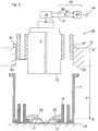
- FIG. 2 Based on Figures 2 to 6 a process sequence for producing the in the Fig. 1 shown assembly state explained.
- the process sequence is carried out in a robot system, of which only one joining station 29 is shown in the figures.
- the joining station 29 is shown in the figures only in a roughly simplified manner insofar as it is necessary to understand the invention.
- the joining station 29 has a storage surface 31 on which the battery housing 1 is positioned.
- the joining station 29 has a stationary centering frame 33, which ensures that the battery module 3 is properly centered from above into the battery housing 1.
- the delivery takes place in the Fig. 2 by means of a robot-controlled delivery device 35, indicated only schematically, by means of which the battery module 3 can be moved into the battery housing 3 via a delivery path z and by means of a delivery force F.
- a force measuring system 37 and a displacement measuring system 39 are assigned to the infeed device 35.
- the force measuring system 37 can be a load cell, by means of which an actual feed force Fist is recorded during the feed process.
- the position measuring system 39 has several, in total at least three circumferentially spaced distance sensors 41, of which in the Figure 2 two displacement sensors 41 are indicated by way of example. Both the force measuring system 37 and the displacement measuring system 39 are in signal connection with an evaluation unit 43 of the monitoring device 40.
- an application process step is carried out in which the thermal paste 25 is applied in a roughly distributed manner.
- the delivery process step in which the delivery device 35 removes the battery module 3 until it reaches the assembly position A ( Fig. 3 ) enters the battery housing 1.
- a feed force curve is recorded over the feed path z, which according to FIG Fig. 2 or 4th is defined between a starting reference point R and the final assembly position A in the vertical direction z.
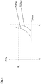
- the actual force / path curve F (z) ist is compared with a target force / path curve F (z) soll in the evaluation unit 43, as in FIG Fig. 4 is indicated.
- the starting reference point R is defined as the top side 12 of the centering frame 33, for example.
- the metrological recording of the delivery path z and the associated delivery force F takes place from the point in time at which the battery module base 10 ( Figure 2 ) the centering frame top 12 passes during the feed movement.
- a height offset between the centering frame top 12 and the screw dome top 14 is measured as an offset value.
- the offset value is identical to the maximum infeed path z that can be covered between the starting reference point R and the assembly position A.
- a target force / path curve F (z) soll is shown with a solid line in a force-path diagram, as is stored in the evaluation unit 43 by way of example. Accordingly, during the infeed movement, the target infeed force F soll remains low until shortly before the assembly position A is reached. Only when the battery module bottom 10 makes contact with the not yet distributed thermal paste 25 ( Figure 2 ) the set delivery force F set to be applied to the battery module 3 increases, to be precise until the assembly position A is reached, at which the set feed force F set is at a value F A.
- an actual force / path curve F (z) is also shown with a dashed line, in which the infeed force F ist already increases significantly earlier than expected. This can indicate an interfering contour that is incorrectly present in the battery housing 1, for example a joining component or the like.
- the evaluating unit 43 determine whether the plunging process step is error free or not. If there is no error-free delivery process step, the battery housing 1 together with the battery module 3 can be fed to a post-processing station, in which manual post-processing of the traction battery can be carried out by a worker.
- a fastening process step follows ( Fig. 5 ), in which the screw bolt 19 is guided through the assembly shaft 47 of the battery module 3 by means of a screw unit 45 and is screwed to the screw dome 21 on the bottom.
- a second monitoring device 49 is assigned to the screwing unit 45, which detects an actual tightening torque M ist during the screwing process and compares it with a target tightening torque M soll. If the actual tightening torque M is the target tightening torque M soll stored in the second monitoring device 49, the screwing process is ended.
Landscapes
- Chemical & Material Sciences (AREA)
- Engineering & Computer Science (AREA)
- Chemical Kinetics & Catalysis (AREA)
- Electrochemistry (AREA)
- General Chemical & Material Sciences (AREA)
- Transportation (AREA)
- Aviation & Aerospace Engineering (AREA)
- Mechanical Engineering (AREA)
- Life Sciences & Earth Sciences (AREA)
- Power Engineering (AREA)
- Sustainable Energy (AREA)
- Sustainable Development (AREA)
- Combustion & Propulsion (AREA)
- Battery Mounting, Suspending (AREA)
- Secondary Cells (AREA)
Description
- Die Erfindung betrifft ein Verfahren zum Fügen zumindest eines Batteriemoduls in ein Batteriegehäuse einer Traktionsbatterie eines Fahrzeugs nach dem Oberbegriff des Anspruchs 1 wie eine Roboteranlage zur Durchführung des Verfahrens nach dem Anspruch 8.
- Die Traktionsbatterie eines elektrisch betriebenen Fahrzeugs weist Batteriezellen auf, die jeweils als Zellenverbund in quaderförmigen Batteriemodulen zusammengefasst sind. Eine Anzahl solcher Batteriemodule kann in einem Batteriegehäuse angeordnet sein, das im Fahrzeug positionierbar ist. Die im Batteriegehäuse angeordneten Batteriemodule können mit einem Kühlsystem gekühlt werden, um eine bessere Betriebsfähigkeit zu erzielen. Das Kühlsystem kann beispielhaft ein fahrzeugseitiger Kühlmittelkreislauf sein, in dem Kühlmittelkanäle im Gehäuseboden des Batteriegehäuses eingebunden sind. Im Hinblick auf eine gute Wärmeleitfähigkeit zwischen dem jeweiligen Batteriemodul und dem Gehäuseboden können wärmeisolierende Luftspalte zwischen dem Batteriemodul und dem Gehäuseboden mit einer Wärmeleitpaste gefüllt sein.
- Eine gattungsgemäße Prozessabfolge zur Herstellung einer solchen Traktionsbatterie wird automatisiert in einer Roboteranlage durchgeführt. Hierzu wird ein noch nicht mit dem Batteriemodul bestücktes Batteriegehäuse in eine Fügestation der Roboteranlage transferiert. In der Fügestation erfolgt zunächst ein Applikations-Prozessschritt, bei dem die Wärmeleitpaste auf den Gehäuseboden des Batteriegehäuses aufgebracht wird. Anschließend erfolgt ein Zustell-Prozessschritt, bei dem eine Zustelleinrichtung das jeweilige Batteriemodul über einen Zustellweg und mittels einer Zustellkraft in das Batteriegehäuse einfährt, und zwar bis Erreichen einer Montageposition, in der das Batteriemodul lagerichtig auf einer Anlagekontur des Gehäusebodens des Batteriegehäuses aufliegt. Das Batteriemodul kann unmittelbar auf der Anlagekontur des Gehäusebodens aufliegen. Alternativ und/oder zusätzlich kann das Batteriemodul auch mittelbar unter Zwischenlage einer Wärmeleitpasten-Schicht auf der Anlagekontur des Gehäusebodens aufliegen. Dem Zustell-Prozessschritt ist ein Befestigungs-Prozessschritt nachgelagert, bei dem das Batteriemodul über Schraubbolzen mit dem Gehäuseboden des Batteriegehäuses verspannt wird.
- Im Stand der Technik wird der Schraubvorgang während des Befestigungs-Prozessschrittes mittels einer Überwachungseinrichtung überwacht, beim Schraubvorgang ein auf den Schraubbolzen wirkendes Ist-Anzugmoment erfasst. Bei Erreichen eines Soll-Anzugmomentes wird der automatisiert durchgeführte Schraubvorgang beendet.
- Im Zustell-Prozessschritt können sich Störkonturen im noch nicht mit dem Batteriemodul bestückten Batteriegehäuse befinden. Dadurch wird ein lagerichtiges Positionieren des Batteriemoduls im Batteriegehäuse beeinträchtigt. Eine solche Störkontur ist beispielhaft eine fehlerhaft im Batteriegehäuse angeordnete Fügekomponente, etwa ein Schraubbolzen, oder dergleichen. Dies kann zu einer fehlerhaften Ablageposition des Batteriemoduls im Batteriegehäuse führen, wodurch die Betriebsfähigkeit des Batteriemoduls beeinträchtigt sein kann.
- Aus der
DE 10 2014 203 765 A1 ist ein Verfahren zur Herstellung einer Baugruppe aus einem Energiespeichermodul und einem Kühlelement bekannt. Aus derDE 21 56 012 A1 ist ein Verfahren sowie eine Vorrichtung zum Anziehen von Schrauben bekannt. Aus derDE 29 18 845 A1 ist ein Verfahren zum Anschrauben eines Halbleiter-Bauteils an einem Kühlblech bekannt. - Die Aufgabe der Erfindung besteht darin, ein Verfahren sowie eine Roboteranlage zur Herstellung einer Traktionsbatterie eines Fahrzeugs bereitzustellen, bei der in einfacher sowie betriebssicherer Weise ein einwandfreier Zusammenbau der Traktionsbatterie gewährleistet ist.
- Die Aufgabe ist durch die Merkmale des Anspruches 1 oder 8 gelöst. Bevorzugte Weiterbildungen der Erfindung sind in den Unteransprüchen offenbart.
- Gemäß dem kennzeichnenden Teil des Anspruches 1 wird der Zustell-Prozessschritt mittels einer Überwachungseinrichtung überwacht. Der Überwachungseinheit ist ein Wegmesssystem zugeordnet, das während des Zustellvorgangs den Ist-Zustellweg erfasst. Zudem ist der Überwachungseinheit ein Kraftmesssystem zugeordnet, das während des Zustellvorgangs eine Ist-Zustellkraft erfasst. Auf der Grundlage des erfassten Ist-Zustellwegs und der erfassten Ist-Zustellkraft wertet die Überwachungseinheit aus, ob der Zustell-Prozessschritt fehlerfrei erfolgt oder nicht. Bei Vorliegen eines fehlerbehafteten Zustell-Prozessschrittes kann die Traktionsbatterie zu einer Nachbearbeitungs-Station transferiert werden, in der beispielhaft der Zustell-Prozessschritt nicht mehr automatisiert, sondern vielmehr manuell durch einen Werker wiederholt wird.
- In einer technischen Umsetzung kann die Überwachungseinrichtung eine Auswerteeinheit aufweisen, die die Ist-Zustellkraft und den Ist-Zustellweg mit damit korrespondierenden Sollwerten vergleicht, die in der Auswerteeinheit zum Beispiel in einer Datenbank tabellarisch hinterlegt sein können. Die Auswerteeinheit kann auf der Grundlage eines Soll-/Istwert-Vergleiches ermitteln, ob ein fehlerfreier Zustell-Prozessschritt vorliegt.
- In einer Ausführungsvariante kann die Überwachungseinrichtung einen Ist-Kraft-/Wegverlauf der Ist-Zustellkraft über den Ist-Zustellweg erfassen. Der Ist-Kraft-/Wegverlauf kann mit einem in der Überwachungseinrichtung hinterlegten Soll-Kraft-/Wegverlauf verglichen werden und auf der Grundlage dieses Vergleichs der Zustell-Prozessschritt bewertet werden.
- Sofern die Überwachungseinrichtung einen einwandfreien Zustell-Prozessschritt ermittelt hat, kann ein prozesstechnisch nachgelagerter Befestigungs-Prozessschritt erfolgen, bei dem beispielhaft das zugestellte Batteriemodul mit dem Gehäuseboden des Batteriegehäuses verspannbar ist. Hierzu wird das Batteriemodul mittels zumindest eines Schraubbolzens an einem Anschraubpunkt des Batteriegehäuses verschraubt. Um eine einwandfreie Befestigung des Batteriemoduls zu gewährleisten, wird der obige Befestigungs-Prozessschritt bevorzugt mittels einer weiteren, zweiten Überwachungseinrichtung überwacht, die auswertet, ob der Befestigungsschritt fehlerfrei erfolgt oder nicht. Bevorzugt kann die zweite Überwachungseinrichtung während des Schraubvorgangs ein auf den Schraubbolzen wirkendes Ist-Anzugmoment erfassen. Das Ist-Anzugmoment kann in der Überwachungseinrichtung mit einem Soll-Anzugmoment verglichen werden. Sofern das Ist-Anzugmoment das Soll-Anzugmoment erreicht, wird der Schraubvorgang beendet.
- Im Gehäuseboden des Batteriegehäuses können Kühlmittelkanäle oder andere Kühlelemente ausgebildet sein, die Bestandteil eines fahrzeugseitigen Kühlsystems sein können. Um die Wärmeleitfähigkeit zwischen dem eingebauten Batteriemodul und dem Gehäuseboden zu erhöhen, können wärmeisolierende Luftspalte zwischen dem Batteriemodul und dem Gehäuseboden mit einer Wärmeleitpaste aufgefüllt sein. Die Wärmeleitpaste kann in einem zeitlich vor dem Zustell-Prozessschritt erfolgenden Applikations-Prozessschritt aufgebracht werden.
- Die Wegkoordinaten der Montageposition können in der Zustelleinrichtung hinterlegt sein. In gleicher Weise kann auch die bei Erreichen der Montageposition auf das Batteriemodul einwirkende Soll-Zustellkraft in der Überwachungseinrichtung hinterlegt sein.
- Nachfolgend ist ein Ausführungsbeispiel der Erfindung anhand der beigefügten Figuren beschrieben. Es zeigen:
- Fig. 1
- In einem Zusammenbauzustand ein in einem Batteriegehäuse verspanntes Batteriemodul;
- Fig. 2 bis 6
- jeweils Ansichten, die eine Prozessabfolge zur Herstellung des in der
Fig. 1 gezeigten Zusammenbauzustands der Traktionsbatterie veranschaulichen. - In der
Fig. 1 ist grob vereinfacht in einer Seitenschnittdarstellung eine Traktionsbatterie eines elektrisch betriebenen Fahrzeugs angedeutet. Die Traktionsbatterie weist ein wannenförmiges oder kastenförmiges Batteriegehäuse 1 auf, in dem ein quaderförmiges Batteriemodul 3 positioniert ist, das aus nicht dargestellten einzelnen Batteriezellen aufgebaut ist. Das Batteriemodul 3 ist mittels Spanneinheiten 5 auf einem Gehäuseboden 7 des Batteriegehäuses 1 montiert. Wie aus derFig. 1 weiter hervorgeht, weist der Gehäuseboden 7 eine Gehäuseboden-Basis 9 sowie davon in Richtung GehäuseInnenraum um eine Prägehöhe hochgezogene Kühlverprägungen 11 auf. Die Kühlverprägungen 11 begrenzen zusammen mit einem unteren Deckblechteil 13 Kühlmittelkanäle 15, die Bestandteile eines externen Fahrzeug-Kühlsystems sind. Die Oberseiten der Kühlverprägungen 11 bilden in derFig. 1 eine Anlagekontur 17, auf der das Batteriemodul 3 unter Zwischenlage einer Wärmeleitpaste-Isolierschicht aufliegt. - Es ist hervorzuheben, dass der Aufbau des Gehäuseboden 7 in den Figuren lediglich beispielhaft ist und die Erfindung keinesfalls auf den in den Figuren gezeigten Aufbau des Gehäusebodens 7 beschränkt ist. Vielmehr kann alternativ zu den Figuren der Gehäuseboden 7 innenseitig ebenflächig ausgebildet sein und können die Kühlkanäle 15 unterhalb des ebenflächigen Gehäusebodens angeordnet sein.
- Wie oben erwähnt, ist das Batteriemodul 3 über die Spanneinheiten 5 fest auf dem Gehäuseboden 7 verspannt. Jede der Spanneinheiten 5 besteht in der
Fig. 1 aus einem Schraubbolzen 19, der durch einen Montageabschnitt 47 des Batteriemoduls 3 geführt ist und in einem am Gehäuseboden 7 befestigten Schraubdom 21 verschraubt ist. In derFig. 1 sind die seitlich an den Kühlverprägungen 11 angrenzenden Luftspalte 23 mittels einer Wärmeleitpaste 25 vollständig aufgefüllt, um die Wärmeleitfähigkeit zwischen dem Batteriemodul 3 und dem kühlmitteldurchströmten Gehäuseboden 7 zu erhöhen. - Das Batteriegehäuse 1 weist außerdem vom Gehäuseboden 7 seitlich nach oben hochgezogene Gehäuse-Seitenwände 27 auf. Auf deren oberen Befestigungsflansch ist ein nicht gezeigter Batteriedeckel befestigbar.
- Anhand der
Fig. 2 bis 6 wird eine Prozessabfolge zur Herstellung des in derFig. 1 gezeigten Zusammenbauzustandes erläutert. Die Prozessabfolge wird in einer Roboteranlage durchgeführt, von der in den Figuren lediglich eine Fügestation 29 gezeigt ist. Die Fügestation 29 ist in den Figuren lediglich grob vereinfacht insoweit dargestellt ist, als es zum Verständnis der Erfindung erforderlich ist. Demzufolge ist in derFigur 2 das noch nicht mit dem Batteriemodul 3 bestückte Batteriegehäuse 1 in die Fügestation 29 (Fig. 2 ) transferiert. Die Fügestation 29 weist eine Ablagefläche 31 auf, auf der das Batteriegehäuse 1 positioniert ist. Zudem weist die Fügestation 29 einen ortsfesten Zentrierrahmen 33 auf, der eine einwandfreie zentrierte Zustellung des Batteriemoduls 3 von oben in das Batteriegehäuse 1 gewährleistet. Die Zustellung erfolgt in derFig. 2 mittels einer nur schematisch angedeuteten, robotergesteuerten Zustelleinrichtung 35, mittels der das Batteriemodul 3 über einen Zustellweg z und mittels einer Zustellkraft F in das Batteriegehäuse 3 einfahrbar ist. - Der Zustelleinrichtung 35 sind ein Kraftmesssystem 37 und ein Wegmesssystem 39 zugeordnet. Das Kraftmesssystem 37 kann eine Kraftmessdose ein, mittels der während des Zustellvorgangs eine Ist-Zustellkraft Fist erfasst wird.
- Mit Hilfe des Wegmesssystems 39 wird ein Ist-Zustellweg zist während des Zustellvorgangs erfasst. Um eine flächenparallele Zustellung zu gewährleisten, ist es bevorzugt, wenn das Wegmesssystem 39 mehrere, insgesamt zumindest drei umfangsseitig voneinander beabstandete Wegsensoren 41 aufweist, von denen in der
Figur 2 beispielhaft zwei Wegsensoren 41 angedeutet sind. Sowohl das Kraftmesssystem 37 als auch das Wegmesssystem 39 sind in Signalverbindung mit einer Auswerteeinheit 43 der Überwachungseinrichtung 40. - Zu Beginn der Prozessabfolge wird ein Applikations-Prozessschritt durchgeführt, bei dem die Wärmeleitpaste 25 grob verteilt aufgebracht wird. Anschließend erfolgt der Zustell-Prozessschritt, bei dem die Zustelleinrichtung 35 das Batteriemodul 3 bis zum Erreichen der Montageposition A (
Fig. 3 ) in das Batteriegehäuse 1 einfährt. In der Auswerteeinheit 43 wird ein Zustellkraft-Verlauf über den Zustellweg z erfasst, der gemäß derFig. 2 oder4 zwischen einem Start-Referenzpunkt R und der endgültigen Montageposition A in der Hochrichtung z definiert ist. Der Ist-Kraft-/Wegverlauf F(z)ist wird mit einem Soll-Kraft-/Wegverlauf F(z)soll in der Auswerteeinheit 43 verglichen, wie es in derFig. 4 angedeutet ist. - In der
Figur 2 ist der Start-Referenzpunkt R beispielhaft als die Oberseite 12 des Zentrierrahmens 33 definiert. Die messtechnische Erfassung des Zustellwegs z und der dazugehörigen Zustellkraft F erfolgt ab dem Zeitpunkt, zu dem der Batteriemodul-Boden 10 (Figur 2 ) bei der Zustellbewegung die Zentrierrahmen-Oberseite 12 passiert. - Vor dem Start der obigen Zustellbewegung wird ein Höhenversatz zwischen der Zentrierrahmen-Oberseite 12 und der Schraubdom-Oberseite 14 als ein Offset-Wert messtechnisch erfasst. Der Offset-Wert ist identisch mit dem maximal zurücklegbaren Zustellweg z zwischen dem Start-Referenzpunkt R und der Montageposition A.
- In der
Figur 4 ist ein Soll-Kraft-/Wegverlauf F(z)soll mit durchgezogener Linie in einem Kraft-Weg-Diagramm gezeigt, wie es beispielhaft in der Auswerteeinheit 43 hinterlegt ist. Demnach bleibt bei der Zustellbewegung die Soll-Zustellkraft Fsoll bis kurz vor Erreichen der Montageposition A gering. Erst bei Kontaktaufnahme des Batteriemodul-Bodens 10 mit der noch nicht verteilten Wärmeleitpaste 25 (Figur 2 ) steigt die auf das Batteriemodul 3 zu beaufschlagende Soll-Zustellkraft Fsoll an, und zwar bis zum Erreichen der Montageposition A, bei der die Soll-Zustellkraft Fsoll bei einem Wert FA liegt. - In der
Fig. 4 ist zudem mit gestrichelter Linie ein Ist-Kraft-/Wegverlauf F(z)ist dargestellt, bei dem die Zustellkraft Fist bereits wesentlich früher als erwartet ansteigt. Dies kann auf eine im Batteriegehäuse 1 fehlerhaft vorhandene Störkontur, etwa eine Fügekomponente oder dergleichen, hindeuten. Mittels des Vergleichs des Soll-Kraft-/Wegverlauf F(z)soll mit dem Ist-Kraft-/Wegverlauf F(z)ist kann die Auswerteeinheit 43 ermitteln, ob der Zustell-Prozessschritt fehlerfrei erfolgt oder nicht. Bei Nichtvorliegen eines fehlerfreien Zustell-Prozessschrittes kann das Batteriegehäuse 1 mitsamt Batteriemodul 3 einer Nachbearbeitungs-Station zugeführt werden, in der eine manuelle Nachbearbeitung der Traktionsbatterie durch einen Werker erfolgen kann. - Bei Vorliegen eines einwandfreien Zustell-Prozessschrittes folgt ein Befestigungs-Prozessschritt (
Fig. 5 ), bei dem mittels einer Schraubeinheit 45 der Schraubbolzen 19 durch den Montageschaft 47 des Batteriemoduls 3 geführt wird und mit dem bodenseitigen Schraubdom 21 verschraubt wird. Der Schraubeinheit 45 ist eine zweite Überwachungseinrichtung 49 zugeordnet, die während des Schraubvorgangs ein Ist-Anzugmoment Mist erfasst und mit einem Soll-Anzugmoment Msoll vergleicht. Sofern das Ist-Anzugmoment Mist das in der zweiten Überwachungseinrichtung 49 hinterlegte Soll-Anzugmoment Msoll erreicht, wird der Schraubvorgang beendet.
Claims (5)
- Verfahren zum Fügen zumindest eines Batteriemoduls (3) in ein Batteriegehäuse (1) einer Traktionsbatterie eines Fahrzeugs, bei dem in einem Zustell-Prozessschritt das Batteriemodul (3) robotergesteuert über einen Zustellweg (z) und mittels einer Zustellkraft (F) in das Batteriegehäuse (1) eingefahren wird, und zwar bis Erreichen einer Montageposition (A), in der das Batteriemodul (3) lagerichtig sowie mittelbar oder unmittelbar auf einer Anlagekontur (17) eines Gehäusebodens (7) des Batteriegehäuses (1) aufliegt, und in einem Befestigungs-Prozessschritt das lagerichtig positionierte Batteriemodul (3) in dem Batteriegehäuse (1) befestigt wird, wobei im Befestigungs-Prozessschritt ein Schraubvorgang erfolgt, bei dem das Batteriemodul (3) mittels zumindest eines Schraubbolzens (19) an einem Anschraubpunkt (21) des Batteriegehäuses (1) verschraubt wird, dadurch gekennzeichnet, dass der Zustell-Prozessschritt mittels einer Überwachungseinrichtung (40) überwacht wird, die während des Zustell-Prozessschritts einen Ist-Zustellweg (zist) und eine Ist-Zustellkraft (Fist) erfasst und auf dieser Grundlage auswertet, ob der Zustell-Prozessschritt fehlerfrei erfolgt oder nicht, dass der Befestigungs-Prozessschritt mittels einer zweiten Überwachungseinrichtung (49) überwacht wird, die auswertet, ob der Befestigungs-Prozessschritt fehlerfrei erfolgt oder nicht, und dass die zweite Überwachungseinrichtung (49) beim Schraubvorgang ein auf den Schraubbolzen (19) wirkendes Ist-Anzugmoment (Mist) erfasst, und bei Erreichen eines Soll-Anzugmoments (Msoll) den Schraubvorgang beendet.
- Verfahren nach Anspruch 1, dadurch gekennzeichnet, dass die Überwachungseinrichtung (40) eine Auswerteeinheit (43) aufweist, die die Ist-Zustellkraft (Fist) und den Ist-Zustellweg (zist) mit damit korrespondierenden Sollwerten vergleicht, und dass die Auswerteeinheit (43) auf der Grundlage dieses Vergleichs ermittelt, ob ein fehlerfreier Zustell-Prozessschritt vorliegt.
- Verfahren nach Anspruch 1 oder 2, dadurch gekennzeichnet, dass die Überwachungseinrichtung (40) einen Ist-Kraft-/Wegverlauf (F(z)ist) der Ist-Zustellkraft (Fist) über den Ist-Zustellweg (zist) erfasst, und dass die Überwachungseinrichtung (40) den Ist-Kraft-/Wegverlauf (F(z)ist) mit einem in der Überwachungseinrichtung (40) hinterlegten Soll-Kraft-/Wegverlauf (F(z)soll) vergleicht.
- Verfahren nach einem der vorhergehenden Ansprüche, dadurch gekennzeichnet, dass prozesstechnisch vor dem Zustell-Prozessschritt ein Applikations-Prozessschritt erfolgt, bei dem eine Wärmeleitpaste (25) auf den Gehäuseboden (7) bzw. die Anlagekontur (17) des Batteriegehäuses (1) aufgebracht wird, und dass die Wärmeleitpaste (25) im Zusammenbauzustand der Traktionsbatterie wärmeisolierende Luftspalte (23) zwischen dem Batteriegehäuseboden (7) und dem Batteriemodul (3) ausfüllt.
- Roboteranlage zur Durchführung eines Verfahrens nach einem der vorhergehenden Ansprüche, mit einer Fügestation (29), die eine Zustelleinrichtung (35) aufweist, mittels der das Batteriemodul (3) über einen Zustellweg (z) und mittels einer Zustellkraft (F) in das Batteriegehäuse (1) einfahrbar ist, und zwar bis Erreichen der Montageposition (A), und die Zustelleinrichtung (35) ein Kraftmesssystem (37) aufweist, mittels dem eine Ist-Zustellkraft (Fist) während des Zustellvorgangs erfassbar ist, und die Zustelleinrichtung (35) ein Wegmesssystem (39) aufweist, mittels dem ein Ist-Zustellweg (zist) während des Zustellvorgangs erfassbar ist, dadurch gekennzeichnet, dass die Zustelleinrichtung (35) eine Überwachungseinheit (40) aufweist, die auf der Grundlage des erfassten Ist-Zustellwegs (zist) und der erfassten Ist-Zustellkraft (Fist) auswertet, ob der Zustell-Prozessschritt fehlerfrei erfolgt oder nicht.
Applications Claiming Priority (2)
| Application Number | Priority Date | Filing Date | Title |
|---|---|---|---|
| DE102018210819.6A DE102018210819A1 (de) | 2018-07-02 | 2018-07-02 | Verfahren zur Herstellung einer Fahrzeug-Traktionsbatterie |
| PCT/EP2019/066042 WO2020007603A1 (de) | 2018-07-02 | 2019-06-18 | Verfahren zur herstellung einer fahrzeug-traktionsbatterie |
Publications (2)
| Publication Number | Publication Date |
|---|---|
| EP3818575A1 EP3818575A1 (de) | 2021-05-12 |
| EP3818575B1 true EP3818575B1 (de) | 2021-12-01 |
Family
ID=66998415
Family Applications (1)
| Application Number | Title | Priority Date | Filing Date |
|---|---|---|---|
| EP19731994.0A Active EP3818575B1 (de) | 2018-07-02 | 2019-06-18 | Verfahren zur herstellung einer fahrzeug-traktionsbatterie |
Country Status (4)
| Country | Link |
|---|---|
| EP (1) | EP3818575B1 (de) |
| CN (1) | CN112272888B (de) |
| DE (1) | DE102018210819A1 (de) |
| WO (1) | WO2020007603A1 (de) |
Cited By (1)
| Publication number | Priority date | Publication date | Assignee | Title |
|---|---|---|---|---|
| EP4509800A4 (de) * | 2023-05-16 | 2026-04-01 | Wuxi Lead Intelligent Equipment Co Ltd | Anomaliedetektionsverfahren und -vorrichtung zur batteriezellenumhüllung sowie elektronische vorrichtung und speichermedium |
Families Citing this family (7)
| Publication number | Priority date | Publication date | Assignee | Title |
|---|---|---|---|---|
| DE102020100898B4 (de) | 2020-01-16 | 2024-01-25 | Lisa Dräxlmaier GmbH | Verfahren und Vorrichtung zum Herstellen eines Wärmeübergangs von Komponenten einer Batterie |
| DE102020116566A1 (de) | 2020-06-24 | 2021-12-30 | Audi Aktiengesellschaft | Verfahren zur Montage einer Hochvoltbatterie sowie Fertigungsanlage zur Montage einer Hochvoltbatterie |
| DE102021104146A1 (de) * | 2021-02-22 | 2022-08-25 | Audi Aktiengesellschaft | Verfahren zum Ermitteln eines Qualitätszustands eines während eines Setzprozesses verwendeten Bauteils und Steuereinrichtung zum Überwachen eines Setzprozesses |
| DE102021104206B4 (de) | 2021-02-23 | 2023-01-19 | Audi Aktiengesellschaft | Messvorrichtung, -anordnung und -verfahren für eine Traktionsbatterie |
| CN216015464U (zh) * | 2021-09-27 | 2022-03-11 | 宁德时代新能源科技股份有限公司 | 一种入壳装置及电池装配设备 |
| DE102023111645B3 (de) | 2023-05-04 | 2024-05-02 | Audi Aktiengesellschaft | Prüfvorrichtung für die Deformation einer Batteriezelle und Verfahren zur Herstellung eines Batteriemoduls mit mehreren geprüften Batteriezellen |
| DE102023123016A1 (de) * | 2023-08-28 | 2025-03-06 | Bayerische Motoren Werke Aktiengesellschaft | Energiespeichermodulherstellverfahren |
Family Cites Families (22)
| Publication number | Priority date | Publication date | Assignee | Title |
|---|---|---|---|---|
| DE2156012A1 (de) | 1971-11-11 | 1973-05-17 | Krause Johann A Maschf | Verfahren und vorrichtung zum anziehen von schrauben und muttern mit motorisch angetriebenen schraubern |
| DE2918845A1 (de) | 1979-05-10 | 1980-11-20 | Licentia Gmbh | Verfahren zum anschrauben eines halbleiter-bauteils an ein kuehlblech und schrauber fuer das verfahren |
| JPS59108283A (ja) * | 1982-12-13 | 1984-06-22 | Shinko Electric Co Ltd | 自動バツテリ−交換機構 |
| DE102004038922A1 (de) * | 2004-08-11 | 2006-02-23 | Manfred Kern | Verfahren und Vorrichtung zur Überwachung von Clinchprozessen |
| JP2009527366A (ja) * | 2006-02-24 | 2009-07-30 | フェルロボティクス コンプライアント ロボット テクノロジー ゲーエムベーハー | ロボットアーム |
| DE102006061752A1 (de) * | 2006-12-28 | 2008-07-03 | Kuka Roboter Gmbh | Roboter und Verfahren zum Programmieren eines Roboters |
| CN201204218Y (zh) * | 2008-05-27 | 2009-03-04 | 天津力神电池股份有限公司 | 锂离子圆柱型电池扣盖机构 |
| CN103201895B (zh) * | 2010-11-16 | 2015-09-02 | 本田技研工业株式会社 | 电池的冷却构造 |
| FR2988040B1 (fr) * | 2012-03-15 | 2014-04-25 | Renault Sa | Systeme de verrouillage/deverrouillage d'un objet sur une structure a elements d'appui et d'alignement integres aux outils |
| JP6181494B2 (ja) * | 2013-09-26 | 2017-08-16 | 日本電産サンキョー株式会社 | バッテリー交換ロボット、バッテリー交換システムおよびバッテリー交換ロボットの制御方法 |
| WO2015045981A1 (ja) * | 2013-09-26 | 2015-04-02 | 日本電産サンキョー株式会社 | バッテリー交換ロボット、バッテリー交換システムおよびバッテリー交換ロボットの制御方法 |
| DE102014203765A1 (de) | 2014-02-28 | 2015-09-03 | Bayerische Motoren Werke Aktiengesellschaft | Verfahren zur Herstellung einer Baugruppe aus einem Energiespeichermodul und einem Kühlelement und Baugruppe |
| DE102014012475A1 (de) * | 2014-08-21 | 2015-03-12 | Daimler Ag | Vorrichtung und Verfahren zur Befestigung eines Energiespeichers |
| DE102014221798A1 (de) * | 2014-10-27 | 2016-04-28 | Kuka Systems Gmbh | Verfahren und Robotersystem zur Nutzung eines Industrieroboters für Prüfaufgaben |
| FR3028949B1 (fr) * | 2014-11-20 | 2017-01-06 | Arthaud Eric | Appareil de mesure dynamique du couple de vissage et dispositif d'absorption d'efforts parasites pour celui-ci |
| KR20160091124A (ko) * | 2015-01-23 | 2016-08-02 | 삼성에스디아이 주식회사 | 이차전지 유닛을 수납하는 하우징을 구비하는 배터리 모듈 |
| CN105253117B (zh) * | 2015-09-30 | 2017-04-12 | 王建排 | 电动汽车中置式电池箱快速卸、装方法 |
| JP2017127908A (ja) * | 2016-01-18 | 2017-07-27 | ファナック株式会社 | ロボットが出力する回転力を用いるねじ締め装置 |
| DE102016115647B3 (de) * | 2016-08-23 | 2017-12-14 | Benteler Automobiltechnik Gmbh | Batterieträger für ein Elektrokraftfahrzeug sowie Verfahren zum Bestücken und Montieren eines Batterieträgers |
| DE102016222824B4 (de) * | 2016-11-18 | 2018-06-28 | Audi Ag | Batterie für ein Kraftfahrzeug und Kraftfahrzeug |
| CN106853639A (zh) * | 2017-01-04 | 2017-06-16 | 河北工业大学 | 一种手机电池自动化装配系统及其控制方法 |
| CN107696051B (zh) * | 2017-11-14 | 2023-06-13 | 深圳市光大激光科技股份有限公司 | 电池模组自动抱夹机械手 |
-
2018
- 2018-07-02 DE DE102018210819.6A patent/DE102018210819A1/de not_active Withdrawn
-
2019
- 2019-06-18 WO PCT/EP2019/066042 patent/WO2020007603A1/de not_active Ceased
- 2019-06-18 CN CN201980030217.8A patent/CN112272888B/zh active Active
- 2019-06-18 EP EP19731994.0A patent/EP3818575B1/de active Active
Cited By (1)
| Publication number | Priority date | Publication date | Assignee | Title |
|---|---|---|---|---|
| EP4509800A4 (de) * | 2023-05-16 | 2026-04-01 | Wuxi Lead Intelligent Equipment Co Ltd | Anomaliedetektionsverfahren und -vorrichtung zur batteriezellenumhüllung sowie elektronische vorrichtung und speichermedium |
Also Published As
| Publication number | Publication date |
|---|---|
| WO2020007603A1 (de) | 2020-01-09 |
| CN112272888B (zh) | 2022-12-13 |
| DE102018210819A1 (de) | 2020-01-02 |
| EP3818575A1 (de) | 2021-05-12 |
| CN112272888A (zh) | 2021-01-26 |
Similar Documents
| Publication | Publication Date | Title |
|---|---|---|
| EP3818575B1 (de) | Verfahren zur herstellung einer fahrzeug-traktionsbatterie | |
| DE69909709T2 (de) | Montageplatz und Verwaltungsverfahren dafür | |
| DE102010039649B4 (de) | Ultraschallschweißvorrichtung und Ultraschallschweißverfahren | |
| DE102013207219B4 (de) | Elektronische Steuervorrichtung | |
| EP1401632A1 (de) | Werkzeug mit einem sensorchip | |
| WO2016150617A1 (de) | Umformwerkzeug und verfahren zur optimierung einer platinenumformung in einem umformwerkzeug | |
| DE102012211117A1 (de) | Seitenpositioniervorrichtung für ein System zum Montieren von Fahrzeugkarosserieplatten | |
| DE102017110696A1 (de) | Stromschiene und Verfahren zur Kontaktierung eines elektrischen Motors | |
| DE3213058A1 (de) | Verfahren und mechanismen zur positionierung eines werkzeuges relativ zu einem werkstueck | |
| DE69203260T2 (de) | Andrückvorrichtung und Verfahren. | |
| DE102019213702A1 (de) | Verfahren zum Herstellen einer toleranzausgeglichenen Verbindung zwischen einem ersten Bauteil und einem zweiten Bauteil und elektrischer Antrieb | |
| EP3928888A1 (de) | Verfahren zur entnahme eines werkstückteils in einer bearbeitungsmaschine, datenverarbeitungsprogramm, sicherungseinrichtung sowie bearbeitungsmaschine | |
| DE102019118249A1 (de) | Bondgerät | |
| DE102006028815B3 (de) | Verfahren zur Herstellung eines elektrischen Hybridbauteils | |
| EP3345717B1 (de) | Andrücksystem, laserfügesystem und verfahren | |
| DE10029293A1 (de) | Vorrichtung und Verfahren zum Laserstrahlschweißen von Blechplatinen | |
| EP3946994B1 (de) | Verfahren zum herstellen einer toleranzausgeglichenen verbindung zwischen einem ersten bauteil und einem zweiten bauteil und elektrischer antrieb | |
| DE102012022151B4 (de) | Vorrichtung und Verfahren zum Heißverstemmen | |
| DE102021108310A1 (de) | Stanzvorrichtung | |
| EP2455741B1 (de) | Verfahren und Vorrichtung zur Bestimmung der Härte eines pressgehärteten Bauteils | |
| EP3471904B1 (de) | Verfahren zur herstellung eines behälters | |
| DE68916939T2 (de) | Schweissgerät. | |
| DE10133116A1 (de) | Verfahren und Anlage zum serienmäßigen Herstellen von Verschraubungen | |
| DE10224402A1 (de) | Schweisszange sowie Verfahren zur Beurteilung der Qualität einer Schweissverbindung | |
| DE10225588B4 (de) | Ultraschallschweißanlage |
Legal Events
| Date | Code | Title | Description |
|---|---|---|---|
| STAA | Information on the status of an ep patent application or granted ep patent |
Free format text: STATUS: UNKNOWN |
|
| STAA | Information on the status of an ep patent application or granted ep patent |
Free format text: STATUS: THE INTERNATIONAL PUBLICATION HAS BEEN MADE |
|
| PUAI | Public reference made under article 153(3) epc to a published international application that has entered the european phase |
Free format text: ORIGINAL CODE: 0009012 |
|
| STAA | Information on the status of an ep patent application or granted ep patent |
Free format text: STATUS: REQUEST FOR EXAMINATION WAS MADE |
|
| 17P | Request for examination filed |
Effective date: 20210202 |
|
| AK | Designated contracting states |
Kind code of ref document: A1 Designated state(s): AL AT BE BG CH CY CZ DE DK EE ES FI FR GB GR HR HU IE IS IT LI LT LU LV MC MK MT NL NO PL PT RO RS SE SI SK SM TR |
|
| REG | Reference to a national code |
Ref country code: DE Ref legal event code: R079 Ref document number: 502019002928 Country of ref document: DE Free format text: PREVIOUS MAIN CLASS: H01M0002100000 Ipc: B60L0050640000 |
|
| GRAJ | Information related to disapproval of communication of intention to grant by the applicant or resumption of examination proceedings by the epo deleted |
Free format text: ORIGINAL CODE: EPIDOSDIGR1 |
|
| STAA | Information on the status of an ep patent application or granted ep patent |
Free format text: STATUS: GRANT OF PATENT IS INTENDED |
|
| GRAP | Despatch of communication of intention to grant a patent |
Free format text: ORIGINAL CODE: EPIDOSNIGR1 |
|
| RIC1 | Information provided on ipc code assigned before grant |
Ipc: H01M 50/20 20210101ALI20210818BHEP Ipc: B60K 1/04 20190101ALI20210818BHEP Ipc: B25J 9/16 20060101ALI20210818BHEP Ipc: B60L 50/64 20190101AFI20210818BHEP |
|
| DAV | Request for validation of the european patent (deleted) | ||
| DAX | Request for extension of the european patent (deleted) | ||
| INTG | Intention to grant announced |
Effective date: 20210906 |
|
| GRAS | Grant fee paid |
Free format text: ORIGINAL CODE: EPIDOSNIGR3 |
|
| GRAA | (expected) grant |
Free format text: ORIGINAL CODE: 0009210 |
|
| STAA | Information on the status of an ep patent application or granted ep patent |
Free format text: STATUS: THE PATENT HAS BEEN GRANTED |
|
| AK | Designated contracting states |
Kind code of ref document: B1 Designated state(s): AL AT BE BG CH CY CZ DE DK EE ES FI FR GB GR HR HU IE IS IT LI LT LU LV MC MK MT NL NO PL PT RO RS SE SI SK SM TR |
|
| REG | Reference to a national code |
Ref country code: GB Ref legal event code: FG4D Free format text: NOT ENGLISH |
|
| REG | Reference to a national code |
Ref country code: AT Ref legal event code: REF Ref document number: 1451450 Country of ref document: AT Kind code of ref document: T Effective date: 20211215 Ref country code: CH Ref legal event code: EP |
|
| REG | Reference to a national code |
Ref country code: DE Ref legal event code: R096 Ref document number: 502019002928 Country of ref document: DE |
|
| REG | Reference to a national code |
Ref country code: IE Ref legal event code: FG4D Free format text: LANGUAGE OF EP DOCUMENT: GERMAN |
|
| REG | Reference to a national code |
Ref country code: LT Ref legal event code: MG9D |
|
| REG | Reference to a national code |
Ref country code: NL Ref legal event code: MP Effective date: 20211201 |
|
| PG25 | Lapsed in a contracting state [announced via postgrant information from national office to epo] |
Ref country code: RS Free format text: LAPSE BECAUSE OF FAILURE TO SUBMIT A TRANSLATION OF THE DESCRIPTION OR TO PAY THE FEE WITHIN THE PRESCRIBED TIME-LIMIT Effective date: 20211201 Ref country code: LT Free format text: LAPSE BECAUSE OF FAILURE TO SUBMIT A TRANSLATION OF THE DESCRIPTION OR TO PAY THE FEE WITHIN THE PRESCRIBED TIME-LIMIT Effective date: 20211201 Ref country code: FI Free format text: LAPSE BECAUSE OF FAILURE TO SUBMIT A TRANSLATION OF THE DESCRIPTION OR TO PAY THE FEE WITHIN THE PRESCRIBED TIME-LIMIT Effective date: 20211201 Ref country code: BG Free format text: LAPSE BECAUSE OF FAILURE TO SUBMIT A TRANSLATION OF THE DESCRIPTION OR TO PAY THE FEE WITHIN THE PRESCRIBED TIME-LIMIT Effective date: 20220301 |
|
| PG25 | Lapsed in a contracting state [announced via postgrant information from national office to epo] |
Ref country code: SE Free format text: LAPSE BECAUSE OF FAILURE TO SUBMIT A TRANSLATION OF THE DESCRIPTION OR TO PAY THE FEE WITHIN THE PRESCRIBED TIME-LIMIT Effective date: 20211201 Ref country code: PL Free format text: LAPSE BECAUSE OF FAILURE TO SUBMIT A TRANSLATION OF THE DESCRIPTION OR TO PAY THE FEE WITHIN THE PRESCRIBED TIME-LIMIT Effective date: 20211201 Ref country code: NO Free format text: LAPSE BECAUSE OF FAILURE TO SUBMIT A TRANSLATION OF THE DESCRIPTION OR TO PAY THE FEE WITHIN THE PRESCRIBED TIME-LIMIT Effective date: 20220301 Ref country code: LV Free format text: LAPSE BECAUSE OF FAILURE TO SUBMIT A TRANSLATION OF THE DESCRIPTION OR TO PAY THE FEE WITHIN THE PRESCRIBED TIME-LIMIT Effective date: 20211201 Ref country code: HR Free format text: LAPSE BECAUSE OF FAILURE TO SUBMIT A TRANSLATION OF THE DESCRIPTION OR TO PAY THE FEE WITHIN THE PRESCRIBED TIME-LIMIT Effective date: 20211201 Ref country code: GR Free format text: LAPSE BECAUSE OF FAILURE TO SUBMIT A TRANSLATION OF THE DESCRIPTION OR TO PAY THE FEE WITHIN THE PRESCRIBED TIME-LIMIT Effective date: 20220302 |
|
| PG25 | Lapsed in a contracting state [announced via postgrant information from national office to epo] |
Ref country code: NL Free format text: LAPSE BECAUSE OF FAILURE TO SUBMIT A TRANSLATION OF THE DESCRIPTION OR TO PAY THE FEE WITHIN THE PRESCRIBED TIME-LIMIT Effective date: 20211201 |
|
| PG25 | Lapsed in a contracting state [announced via postgrant information from national office to epo] |
Ref country code: SM Free format text: LAPSE BECAUSE OF FAILURE TO SUBMIT A TRANSLATION OF THE DESCRIPTION OR TO PAY THE FEE WITHIN THE PRESCRIBED TIME-LIMIT Effective date: 20211201 Ref country code: SK Free format text: LAPSE BECAUSE OF FAILURE TO SUBMIT A TRANSLATION OF THE DESCRIPTION OR TO PAY THE FEE WITHIN THE PRESCRIBED TIME-LIMIT Effective date: 20211201 Ref country code: RO Free format text: LAPSE BECAUSE OF FAILURE TO SUBMIT A TRANSLATION OF THE DESCRIPTION OR TO PAY THE FEE WITHIN THE PRESCRIBED TIME-LIMIT Effective date: 20211201 Ref country code: PT Free format text: LAPSE BECAUSE OF FAILURE TO SUBMIT A TRANSLATION OF THE DESCRIPTION OR TO PAY THE FEE WITHIN THE PRESCRIBED TIME-LIMIT Effective date: 20220401 Ref country code: ES Free format text: LAPSE BECAUSE OF FAILURE TO SUBMIT A TRANSLATION OF THE DESCRIPTION OR TO PAY THE FEE WITHIN THE PRESCRIBED TIME-LIMIT Effective date: 20211201 Ref country code: EE Free format text: LAPSE BECAUSE OF FAILURE TO SUBMIT A TRANSLATION OF THE DESCRIPTION OR TO PAY THE FEE WITHIN THE PRESCRIBED TIME-LIMIT Effective date: 20211201 Ref country code: CZ Free format text: LAPSE BECAUSE OF FAILURE TO SUBMIT A TRANSLATION OF THE DESCRIPTION OR TO PAY THE FEE WITHIN THE PRESCRIBED TIME-LIMIT Effective date: 20211201 |
|
| REG | Reference to a national code |
Ref country code: DE Ref legal event code: R097 Ref document number: 502019002928 Country of ref document: DE |
|
| PG25 | Lapsed in a contracting state [announced via postgrant information from national office to epo] |
Ref country code: IS Free format text: LAPSE BECAUSE OF FAILURE TO SUBMIT A TRANSLATION OF THE DESCRIPTION OR TO PAY THE FEE WITHIN THE PRESCRIBED TIME-LIMIT Effective date: 20220401 |
|
| PLBE | No opposition filed within time limit |
Free format text: ORIGINAL CODE: 0009261 |
|
| STAA | Information on the status of an ep patent application or granted ep patent |
Free format text: STATUS: NO OPPOSITION FILED WITHIN TIME LIMIT |
|
| PG25 | Lapsed in a contracting state [announced via postgrant information from national office to epo] |
Ref country code: DK Free format text: LAPSE BECAUSE OF FAILURE TO SUBMIT A TRANSLATION OF THE DESCRIPTION OR TO PAY THE FEE WITHIN THE PRESCRIBED TIME-LIMIT Effective date: 20211201 Ref country code: AL Free format text: LAPSE BECAUSE OF FAILURE TO SUBMIT A TRANSLATION OF THE DESCRIPTION OR TO PAY THE FEE WITHIN THE PRESCRIBED TIME-LIMIT Effective date: 20211201 |
|
| 26N | No opposition filed |
Effective date: 20220902 |
|
| PG25 | Lapsed in a contracting state [announced via postgrant information from national office to epo] |
Ref country code: MC Free format text: LAPSE BECAUSE OF FAILURE TO SUBMIT A TRANSLATION OF THE DESCRIPTION OR TO PAY THE FEE WITHIN THE PRESCRIBED TIME-LIMIT Effective date: 20211201 |
|
| REG | Reference to a national code |
Ref country code: CH Ref legal event code: PL |
|
| REG | Reference to a national code |
Ref country code: BE Ref legal event code: MM Effective date: 20220630 |
|
| PG25 | Lapsed in a contracting state [announced via postgrant information from national office to epo] |
Ref country code: LU Free format text: LAPSE BECAUSE OF NON-PAYMENT OF DUE FEES Effective date: 20220618 Ref country code: LI Free format text: LAPSE BECAUSE OF NON-PAYMENT OF DUE FEES Effective date: 20220630 Ref country code: IE Free format text: LAPSE BECAUSE OF NON-PAYMENT OF DUE FEES Effective date: 20220618 Ref country code: CH Free format text: LAPSE BECAUSE OF NON-PAYMENT OF DUE FEES Effective date: 20220630 |
|
| PG25 | Lapsed in a contracting state [announced via postgrant information from national office to epo] |
Ref country code: IT Free format text: LAPSE BECAUSE OF FAILURE TO SUBMIT A TRANSLATION OF THE DESCRIPTION OR TO PAY THE FEE WITHIN THE PRESCRIBED TIME-LIMIT Effective date: 20211201 Ref country code: BE Free format text: LAPSE BECAUSE OF NON-PAYMENT OF DUE FEES Effective date: 20220630 |
|
| P01 | Opt-out of the competence of the unified patent court (upc) registered |
Effective date: 20230530 |
|
| PG25 | Lapsed in a contracting state [announced via postgrant information from national office to epo] |
Ref country code: MK Free format text: LAPSE BECAUSE OF FAILURE TO SUBMIT A TRANSLATION OF THE DESCRIPTION OR TO PAY THE FEE WITHIN THE PRESCRIBED TIME-LIMIT Effective date: 20211201 Ref country code: CY Free format text: LAPSE BECAUSE OF FAILURE TO SUBMIT A TRANSLATION OF THE DESCRIPTION OR TO PAY THE FEE WITHIN THE PRESCRIBED TIME-LIMIT Effective date: 20211201 |
|
| PG25 | Lapsed in a contracting state [announced via postgrant information from national office to epo] |
Ref country code: HU Free format text: LAPSE BECAUSE OF FAILURE TO SUBMIT A TRANSLATION OF THE DESCRIPTION OR TO PAY THE FEE WITHIN THE PRESCRIBED TIME-LIMIT; INVALID AB INITIO Effective date: 20190618 |
|
| PG25 | Lapsed in a contracting state [announced via postgrant information from national office to epo] |
Ref country code: TR Free format text: LAPSE BECAUSE OF FAILURE TO SUBMIT A TRANSLATION OF THE DESCRIPTION OR TO PAY THE FEE WITHIN THE PRESCRIBED TIME-LIMIT Effective date: 20211201 |
|
| PG25 | Lapsed in a contracting state [announced via postgrant information from national office to epo] |
Ref country code: MT Free format text: LAPSE BECAUSE OF FAILURE TO SUBMIT A TRANSLATION OF THE DESCRIPTION OR TO PAY THE FEE WITHIN THE PRESCRIBED TIME-LIMIT Effective date: 20211201 |
|
| PGFP | Annual fee paid to national office [announced via postgrant information from national office to epo] |
Ref country code: DE Payment date: 20250630 Year of fee payment: 7 |
|
| PGFP | Annual fee paid to national office [announced via postgrant information from national office to epo] |
Ref country code: GB Payment date: 20250621 Year of fee payment: 7 |
|
| PGFP | Annual fee paid to national office [announced via postgrant information from national office to epo] |
Ref country code: FR Payment date: 20250617 Year of fee payment: 7 |
|
| REG | Reference to a national code |
Ref country code: AT Ref legal event code: MM01 Ref document number: 1451450 Country of ref document: AT Kind code of ref document: T Effective date: 20240618 |
|
| PG25 | Lapsed in a contracting state [announced via postgrant information from national office to epo] |
Ref country code: AT Free format text: LAPSE BECAUSE OF NON-PAYMENT OF DUE FEES Effective date: 20240618 |
|
| PG25 | Lapsed in a contracting state [announced via postgrant information from national office to epo] |
Ref country code: SI Free format text: LAPSE BECAUSE OF FAILURE TO SUBMIT A TRANSLATION OF THE DESCRIPTION OR TO PAY THE FEE WITHIN THE PRESCRIBED TIME-LIMIT Effective date: 20211201 |
|
| PGFP | Annual fee paid to national office [announced via postgrant information from national office to epo] |
Ref country code: AT Payment date: 20260410 Year of fee payment: 5 |