EP3818310B1 - Klimagerät - Google Patents
Klimagerät Download PDFInfo
- Publication number
- EP3818310B1 EP3818310B1 EP19722818.2A EP19722818A EP3818310B1 EP 3818310 B1 EP3818310 B1 EP 3818310B1 EP 19722818 A EP19722818 A EP 19722818A EP 3818310 B1 EP3818310 B1 EP 3818310B1
- Authority
- EP
- European Patent Office
- Prior art keywords
- support arms
- component
- air
- functional
- conditioning unit
- Prior art date
- Legal status (The legal status is an assumption and is not a legal conclusion. Google has not performed a legal analysis and makes no representation as to the accuracy of the status listed.)
- Active
Links
Images


Classifications
-
- B—PERFORMING OPERATIONS; TRANSPORTING
- B60—VEHICLES IN GENERAL
- B60H—ARRANGEMENTS OF HEATING, COOLING, VENTILATING OR OTHER AIR-TREATING DEVICES SPECIALLY ADAPTED FOR PASSENGER OR GOODS SPACES OF VEHICLES
- B60H1/00—Heating, cooling or ventilating devices
- B60H1/00357—Air-conditioning arrangements specially adapted for particular vehicles
- B60H1/00364—Air-conditioning arrangements specially adapted for particular vehicles for caravans or trailers
-
- F—MECHANICAL ENGINEERING; LIGHTING; HEATING; WEAPONS; BLASTING
- F24—HEATING; RANGES; VENTILATING
- F24F—AIR-CONDITIONING; AIR-HUMIDIFICATION; VENTILATION; USE OF AIR CURRENTS FOR SCREENING
- F24F13/00—Details common to, or for air-conditioning, air-humidification, ventilation or use of air currents for screening
- F24F13/30—Arrangement or mounting of heat-exchangers
-
- F—MECHANICAL ENGINEERING; LIGHTING; HEATING; WEAPONS; BLASTING
- F24—HEATING; RANGES; VENTILATING
- F24F—AIR-CONDITIONING; AIR-HUMIDIFICATION; VENTILATION; USE OF AIR CURRENTS FOR SCREENING
- F24F1/00—Room units for air-conditioning, e.g. separate or self-contained units or units receiving primary air from a central station
- F24F1/06—Separate outdoor units, e.g. outdoor unit to be linked to a separate room comprising a compressor and a heat exchanger
- F24F1/14—Heat exchangers specially adapted for separate outdoor units
- F24F1/16—Arrangement or mounting thereof
-
- B—PERFORMING OPERATIONS; TRANSPORTING
- B60—VEHICLES IN GENERAL
- B60H—ARRANGEMENTS OF HEATING, COOLING, VENTILATING OR OTHER AIR-TREATING DEVICES SPECIALLY ADAPTED FOR PASSENGER OR GOODS SPACES OF VEHICLES
- B60H1/00—Heating, cooling or ventilating devices
- B60H1/00007—Combined heating, ventilating, or cooling devices
- B60H1/00207—Combined heating, ventilating, or cooling devices characterised by the position of the HVAC devices with respect to the passenger compartment
- B60H2001/00235—Devices in the roof area of the passenger compartment
Definitions
- the present invention relates to an air conditioner.
- the air conditioning unit is designed for installation on a roof.
- the air conditioning device has a plurality of functional components.
- the functional components of the plurality of functional components are arranged in a housing.
- the housing has a mounting side for roof mounting.
- the air conditioner has two carrying arms.
- the two support arms carry the at least one functional component of the plurality of functional components such that the at least one functional component is arranged higher from the fastening side than other functional components that also belong to the plurality of functional components.
- the roof is e.g. B. Part of a vehicle or a boat or generally a room that is e.g. B. should be cooled.
- the roof can therefore also generally be a ceiling of a room.
- An air conditioning unit (an alternative name is air conditioning) is used, for example, to cool the interior of caravans or boats.
- the required functional components are located in a surrounding housing that is attached to a roof with a fastening side. For example, below the roof is the room that is to be cooled by the air conditioning system.
- the principle underlying air cooling of generating cold by means of a cooling circuit has been known for a long time and is used, for example, in WO 2007/042065 A1 described.
- the housing has a holder made of a foamed plastic material with a complex structure.
- An air conditioning unit in which the capacitor is arranged elevated on a base plate shows this WO 2006/021226 A1 .
- An air conditioning system with an elevated heat exchanger shows this DE 10 2006 009 735 A1 .
- document EP2792964 shows an air conditioning device with the features of the preamble of claim 1.
- the aim is to make products as modular as possible. It is also advantageous to reduce the products to a consistent core with elements that can be adapted to the market concerned. It is also advantageous if the structure consists of components or elements that are as simple as possible, which increases the probability that they are identical or easy to manufacture in all countries. Air conditioning systems are complex products that need to be adapted to markets based on consumer standards and preferences. For example, consider the different specifications for the refrigerant to be used. In addition, the interaction of so many and so different components shows that it is not effortless to meet the same high demands for optimal production in different regions.
- the object of the invention is therefore to propose an air conditioning system that can be manufactured as simply as possible and which also allows easy adaptation to different manufacturing conditions.
- the air conditioning system according to the invention should therefore in particular also be an alternative to the prior art.
- the at least one functional component is higher than other functional components from the fastening side (seen or arranged relative thereto).
- the two sides of the functional component which are each held by a support arm, are in particular two opposite sides of the functional component.
- the two front end regions of the two support arms, which each carry the at least one functional component run essentially at the same level, so that a flat area results between the two support arms on this upper end face, which is of the two support arms for the higher one Functional component is clamped.
- the capital letter "S" shape of the carrying arms can be rounded or free of roundings or in a mixed form.
- the two support arms can also each have the shape of the capital letter "Z" without the middle crossbar.
- the capital letter "S” can also be mirrored.
- a functional component is arranged higher than all other functional components.
- the at least one functional component is arranged higher than part of the majority of the functional components.
- the functional components of the air conditioning system are, for example, a condenser, a compressor, an expansion device, an evaporator, a refrigerant reservoir (e.g. a tank) or an electronic unit for controlling the other functional components.
- Other functional components include, for example, a fan, e.g. B. a fan assigned to the condenser or the evaporator.
- the two support arms thus help to simplify the structure of the air conditioning system and the use of components with reduced complexity is sufficient.
- the at least one functional component is connected to the two support arms, e.g. B. firmly connected by screws, bolts or adhesive processes.
- the two support arms are designed to be mirror-symmetrical to one another.
- the two support arms are therefore basically designed the same, but are mirrored to one another. This configuration is relevant, for example, if the two support arms laterally enclose the at least one functional component or even in one embodiment represent the side support structures along a longitudinal extent of the air conditioning system.
- the support arms have a C-profile.
- a C-profile is a relatively simple structure, which therefore does not place any great demands on the initial workpieces or possibly semi-finished products.
- the C-profile is usually also a mechanically stable shape. If the two support arms are designed to be mirror-symmetrical, in one embodiment the C-profiles of the two support arms each open inwards and thus in the direction of the higher functional component.
- the invention provides that the at least one functional component is partially arranged in an area enclosed by the C-profile.
- the functional component rests partially in the area that forms the "C" of the C-profile.
- Both support arms are designed with a C-profile, the two support arms include the functional component and the functional component each has two side sections in the areas covered by the C-profiles.
- One embodiment is that the two support arms are contacted with one another at the front by means of a closing element.
- the end element functions as a type of cap for the end faces of the two support arms.
- one embodiment also results in increased stability.
- a support arm is designed in one piece or in one piece.
- the two support arms are one-piece steel components.
- At least one support arm of the at least two support arms is designed in several parts and has at least two sub-components.
- a carrying arm consists of several parts or individual pieces that are suitably designed and connected to one another. Based on this, the structure or shape of the support arm can also be broken down into partial structures, which are therefore correspondingly simpler and therefore easier to manufacture.
- a partial component forms an end face of the support arm, which carries the at least one (and thus higher) functional component.
- the front side of a support arm in particular is a partial component. It is therefore possible, for example, for e.g. B. (suitable to the respective standards) differently sized functional components (to be arranged higher) to provide a suitable sub-component of the support arms and to connect them to the remaining sub-components of the support arms (preferably consistent across the variants). Therefore, even for different functional components, at least one constant partial component of the support arms can still be used.
- a partial component forms an end face of the support arm, which carries functional components of the plurality of functional components, to which the at least one functional component is arranged higher.
- a partial component forms the (hence lower) end face, which carries the functional components arranged lower down. It is therefore essentially the reverse design of the aforementioned design.
- At least one support arm of the at least two support arms is designed in several parts and has three sub-components, that a first sub-component forms an end face of the support arm, which carries the at least one functional component, that a second sub-component forms another end face of the support arm, which Carries functional components of the plurality of functional components, to which the at least one functional component is arranged higher, and that a third subcomponent serves for the connection between the first subcomponent and the second subcomponent.
- a support arm consists of three sub-components that form the two end faces and a middle piece between the end areas.
- the middle piece i.e. the third subcomponent
- the middle piece preferably causes the height difference between one functional component arranged higher and the other functional components arranged lower. Since the other two sub-components (first and second sub-components) each carry the functional components and are therefore also dependent on their respective shape and design, - in one embodiment variant - these are to choose two sub-components (i.e. the first and the second sub-component) appropriately and the shape of the middle piece (i.e. the third sub-component) is retained. This makes it possible to address different design variants or specific country requirements while maintaining a uniform basic form.
- subcomponents of the at least two or three subcomponents consist of different materials.
- the different materials also include different manufacturing methods.
- at least one support arm (preferably both support arms) consists of different materials, which are each assigned to the subcomponents.
- the air conditioning device has an insulation component, and that the insulation component thermally insulates some functional components of the plurality of functional components, to which the at least one functional component is arranged higher.
- the functional components that are at the lower level are converted into an isolation component, e.g. B. a kind of box made of plastic is introduced.
- the air conditioning device has a surrounding component, and that the surrounding component forms at least the outer sides of the air conditioning device that deviate from the fastening side of the air conditioning device.
- the surrounding component is a deep-drawn housing made of plastic.
- the surrounding component serves the actual appearance of the air conditioning system and forms the external finish. Therefore, the surrounding component can consist, for example, of a plastic, which also allows a corresponding color or haptic or weather-resistant design.
- a fan is arranged in the surrounding component.
- the fan is located above the functional component, which is arranged above the other functional components.
- the fan is assigned to a condenser as a functional component, so that it is a condenser fan.
- the air conditioning device has an air distributor, and that the air distributor is designed to be connectable to the support arms - directly or indirectly, depending on the design.
- the air distributor is designed to be connectable to the support arms - directly or indirectly, depending on the design.
- a breakthrough is created in the roof during assembly, so that the air distributor below and the other components and thus also the support arms and the functional components above the roof can be connected to one another.
- the two support arms carry exactly one functional component in such a way that exactly one functional component is arranged higher than the other functional components from the fastening side.
- only one functional component is explicitly held higher than the other functional components by the two support arms.
- the aforementioned fan which is assigned to the condenser, would be a functional component that does not belong to those functional components that are arranged lower than the increased functional component (preferably the condenser in the exemplary embodiment).
- One functional component is therefore not arranged higher than all other functional components, but only higher than one part.
- the deeper functional components are, for example, those with a higher weight.
- One embodiment provides that the at least one (or in one embodiment the only) functional component that the two support arms carry is a condenser.
- the functional components of the plurality of functional components, to which the at least one functional component is arranged higher include a compressor, an expansion device, an evaporator and/or a refrigerant reservoir.
- At least one support arm consists at least partially of an extruded part.
- the two support arms are each extruded parts or at least partially consist of them.
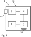
- the Fig. 1 shows schematically the structure of an air conditioning system 1 for cooling a room, e.g. B. the interior of a vehicle.
- the resulting cooling circuit or cooling process is, for example, in the WO 2007/042065 A1 described.
- a compressor compresses a gaseous refrigerant, which then absorbs heat and is transported via a refrigerant line to a liquefier (alternative name: condenser) 3.
- the condenser 3 serves as a heat exchanger by releasing the heat of the refrigerant into the cooler ambient air. The ambient air is sucked in via a condenser fan 9a and blown out again after interacting with the refrigerant. As the heat is released, the compressed refrigerant liquefies.
- the liquid and still under high pressure refrigerant is in an expansion device 4, which z. B. is designed as a throttle, relaxed to a lower pressure.
- the refrigerant cools down.
- the refrigerant reaches an evaporator 5, through which the air of the room to be cooled - i.e. z. B. the interior of a caravan or a Motorhome - is guided by an evaporator fan 9b.
- the air transfers its heat to the refrigerant, which turns into a gaseous state.
- the gaseous refrigerant ultimately returns to the compressor 2 so that the cooling cycle can continue.
- the cycle can also be reversed so that the device 1 serves as a space heater.
- the components described are exemplary functional components of the air conditioning system 1 and are located partly in the interior or partly in the wall of a housing 10.
- the Fig. 2 shows schematically the basic appearance of the air conditioning system 1.
- the air conditioning system 1 is mounted here on a roof 100 and extends through recesses in this roof 100 to an air distributor 40 in the interior, which is to be cooled by the air conditioning system 1. If the roof 100 belongs to a vehicle, the air conditioning system 1 is fixed on the roof 100 in the direction of travel. The cavity between the air conditioning system 1 and the roof 100 is therefore located in the direction of travel behind the area of the air conditioning system 1, which rests on the roof 100.
- the support arm 20 is designed here in three parts and has two sub-components 26, 27, which form the end faces 21, 22, and a middle sub-component 25, which causes the height difference between the other two sub-components 26, 27.
- the upper sub-component 27 and the lower sub-component 26 are designed to be flat, so that they are correspondingly easy-to-manufacture components.
- the actual S shape is only in the middle component 25.
- the condenser 3 Below the condenser 3 there is a cavity to the roof 100, which is freely accessible to air.
- a fan 9a assigned to the condenser i.e. a condenser fan
- the end side of the support arm 20 and thus the free end of the first sub-component 27 is protected by a closing element 23 closed, which also contacts the other support arm - not shown here (cf. Fig. 4 ).
- the second or lower subcomponent 26 is located in the direction of the second end face 22. This subcomponent 26 carries the other functional components.
- the evaporator 5 and the evaporator fan 9b are located in the insulation component 30. It can also be seen that the room air is sucked in through a recess and cooled by the evaporator fan 9b and is introduced back into the room via another recess in the roof 100 .
- the room air to be cooled is therefore also passed through the insulation component 30.
- the functional components are located on the lower sub-component 26, but can also be located in between - i.e. between the two support arms 30.
- the functional components are housed here in an insulation component 30, which causes thermal insulation.
- the support arms 20 are made in one piece and are preferably extruded parts made of steel.
- the air conditioning system 1 is connected to the roof 100 via the fastening side 11, with the lower end face 22 of the support arms 20 also ensuring the mechanical fastening and stability.
- the fixation is indicated here by two screw or bolt-like fixing elements 41.
- the other sides of the air conditioning system 1 are formed by a surrounding component 31, which is, for example, a deep-drawn housing made of plastic.
- This enclosing component 31 does not fulfill a holding function, but essentially only serves to protect the actual components of the air conditioning system 1 from the outside world.
- the surrounding component 31 is located in the one shown Design in particular also includes a recess in which the condenser fan 9a is inserted.
- the enclosing component 31 (alternative name would be enclosing housing) ends in the direction of the fastening side 11 or the roof 100 at the height of the lower edge of the support arms 20.
- the two support arms 20 each have a C-profile and that the functional component 3 rests in the areas that are encompassed by the C-profiles and are preferably also fixed there.
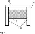
- the Fig. 4 shows the end face 21, which includes the upper part of the capital letter "S" of the support arms 20 (cf. Fig. 2 ).
- the functional component 3 rests laterally in the support arms 20, such as. B. in the Fig. 3 shown.
- the two end regions of the functional components 3 are still connected to one another via a closing element 23.
- the end element 23 is located in a configuration - similar to a plug - in the open ends of the C-profiles of the support arms 20.
Landscapes
- Engineering & Computer Science (AREA)
- Mechanical Engineering (AREA)
- Chemical & Material Sciences (AREA)
- Combustion & Propulsion (AREA)
- General Engineering & Computer Science (AREA)
- Physics & Mathematics (AREA)
- Thermal Sciences (AREA)
- Air-Conditioning For Vehicles (AREA)
Description
- Die vorliegende Erfindung betrifft ein Klimagerät. Dabei ist das Klimagerät zur Montage auf einem Dach ausgestaltet. Das Klimagerät weist eine Mehrzahl von Funktionskomponenten auf. Die Funktionskomponenten der Mehrzahl von Funktionskomponenten sind in einem Gehäuse angeordnet. Das Gehäuse weist eine Befestigungsseite für die Montage auf dem Dach auf. Das Klimagerät weist zwei Tragearme auf. Die zwei Tragearme tragen die mindestens eine Funktionskomponente der Mehrzahl von Funktionskomponenten so, dass die mindestens eine Funktionskomponente von der Befestigungsseite aus höher als andere Funktionskomponenten, die ebenfalls zu der Mehrzahl von Funktionskomponenten gehören, angeordnet ist. Das Dach ist z. B. Teil eines Fahrzeugs oder eines Boots oder allgemein eines Raumes, der durch das Klimagerät z. B. gekühlt werden soll. Das Dach kann somit auch allgemein eine Decke eines Raumes sein.
- Ein Klimagerät (eine alternative Bezeichnung ist Klimaanlage) dient beispielsweise zum Kühlen von Innenräumen von Wohnwagen oder Booten. Dabei befinden sich die erforderlichen Funktionskomponenten in einem umgebenden Gehäuse, das mit einer Befestigungsseite auf einem Dach befestigt wird. Unterhalb des Dachs befindet sich beispielsweise der Raum, der durch die Klimaanlage gekühlt werden soll.
- Das der Luftkühlung zugrundeliegende Prinzip der Kälteerzeugung mittels eines Kühlkreislaufs ist seit langem bekannt und beispielsweise in der
WO 2007/042065 A1 beschrieben. Das Gehäuse verfügt über eine Halterung aus einem geschäumten und eine komplexe Struktur aufweisenden Kunststoffmaterial. Ein Klimagerät, in welchem der Kondensator auf einer Grundplatte erhöht angeordnet ist, zeigt dieWO 2006/021226 A1 . Eine Klimaanlage mit einem erhöht angeordneten Wärmetauscher zeigt dieDE 10 2006 009 735 A1 . DokumentEP2792964 zeigt ein Klimagerät mit den Merkmalen des Oberbegriffs von Anspruch 1. - Heutzutage werden Produkte häufig nicht nur in einem Land, sondern weltweit hergestellt und vertrieben. Einerseits sind daher, bedingt durch die jeweiligen Normen, Vorgaben, Bedürfnisse oder Anforderungen, solche Produkte für den jeweiligen Markt zu adaptieren. Andererseits kann sich auch zeigen, dass die Fertigung selbst nicht überall auf dem gleichen Niveau durchgeführt werden kann.
- Ziel ist es somit, Produkte möglichst modular auszugestalten. Vorteilhaft ist es zudem, die Produkte auf einen stets gleichbleibenden Kern mit auf den betroffenen Markt anzupassenden Elementen zu reduzieren. Dabei ist es auch vorteilhaft, wenn der Aufbau aus möglichst einfachen Bauteile oder Elementen besteht, die die Wahrscheinlichkeit erhöhen, dass sie in allen Ländern identisch gegeben oder einfach herzustellen sind. Klimaanlagen sind solche komplexen Produkte, die jeweils infolge von Normen und Vorlieben der Verbraucher für die Märkte anzupassen sind. So denke man beispielsweise an die unterschiedlichen Vorgaben für das jeweils zu verwendende Kältemittel. Zudem zeigt sich auch bei dem Zusammenspiel von so vielen und so unterschiedlichen Bestandteilen, dass es nicht aufwandsfrei ist, in unterschiedlichen Regionen die gleichen hohen Ansprüche an die optimale Fertigung zu erfüllen.
- Die Aufgabe der Erfindung besteht daher darin, eine Klimaanlage vorzuschlagen, die sich möglichst einfach fertigen lässt und die auch eine leichte Adaptierung an unterschiedliche Fertigungsbedingungen erlaubt. Bei der erfindungsgemäßen Klimaanlage soll es sich somit insbesondere auch um eine Alternative zum Stand der Technik handeln.
- Die Erfindung löst die Aufgabe durch die Merkmale des Anspruchs 1 bzw. des Anspruchs 2. Durch die zwei Tragearme befindet sich die mindestens eine Funktionskomponente von der Befestigungsseite aus (gesehen oder relativ dazu angeordnet) höher als andere Funktionskomponenten. Bei den zwei Seiten der Funktionskomponente, die jeweils von einem Tragearm gehalten werden, handelt es sich insbesondere um zwei einander gegenüberliegende Seite der Funktionskomponente. Die beiden stirnseitigen Endbereiche der zwei Tragearme, die jeweils die mindestens eine Funktionskomponente tragen, verlaufen in einer Ausgestaltung im Wesentlichen auf einem gleichen Niveau, sodass sich zwischen beiden Tragearmen an dieser oberen Stirnseite ein planer Bereich ergibt, der von den zwei Tragearmen für die höher angeordnete Funktionskomponente aufgespannt wird. Die Form des Großbuchstabens "S" der Tragearme kann dabei gerundet oder frei von Abrundungen sein oder in einer Mischform verlaufen. Gemäß der Erfindung können die zwei Tragearme auch jeweils die Form des Großbuchstabens "Z" ohne den mittleren Querbalken aufweisen. Der Großbuchstabe "S" kann auch gespiegelt sein.
- Gemäß der Erfindung ist eine Funktionskomponente höher als alle anderen Funktionskomponenten angeordnet. In einer alternativen Ausgestaltung ist die mindestens eine Funktionskomponente höher als ein Teil der Mehrzahl der Funktionskomponenten angeordnet.
- Die Funktionskomponenten der Klimaanlage sind dabei beispielsweise ein Verflüssiger, ein Kompressor, eine Expansionsvorrichtung, ein Verdampfer, ein Kältemittelreservoir (z. B. ein Tank) oder auch eine Elektronikeinheit zum Steuern der anderen Funktionskomponenten. Weitere Funktionskomponente sind beispielsweise ein Gebläse, z. B. ein dem Verflüssiger oder dem Verdampfer zugeordnetes Gebläse.
- Durch die höher gelegene Positionierung und den damit verbundenen internen Aufbau der Klimaanlage ergibt sich in einer Ausgestaltung insbesondere ein Hohlbereich zum Dach unterhalb der Funktionskomponente, der in einer Ausgestaltung von Luft frei durchströmt wird.
- Durch das Höherlegen eines Teils der Klimaanlage ergibt sich auch der Vorteil, dass die Auflagefläche der Klimaanlage auf dem Dach für die Montage reduziert wird.
- Die zwei Tragearme tragen somit dazu bei, dass die Struktur der Klimaanlage vereinfacht wird und die Verwendung von Bauteilen mit reduzierter Komplexität ausreichend ist.
- In einer Ausgestaltung ist die mindestens eine Funktionskomponente mit den beiden Tragearmen, z. B. durch Schrauben, durch Bolzen oder durch Klebeprozesse fest verbunden.
- Gemäß einer Ausgestaltung sind die zwei Tragearme spiegelsymmetrisch zueinander ausgestaltet. Die zwei Tragearme sind somit prinzipiell gleich ausgestaltet, sind jedoch gespiegelt zueinander ausgeführt. Diese Ausgestaltung ist beispielsweise dann relevant, wenn die zwei Tragearme die mindestens eine Funktionskomponente seitlich umfassen oder gar in einer Ausgestaltung die seitlichen Tragestrukturen entlang einer Längserstreckung der Klimaanlage darstellen.
- Gemäß der Erfindung weisen die Tragarme ein C-Profil auf. Ein C-Profil ist eine relativ einfache Struktur, die somit keine großen Anforderungen an die Ausgangswerkstücke oder ggf. Halbzeuge stellt. Das C-Profil ist in der Regel auch eine mechanisch stabile Form. Sind die beiden Tragearme spiegelsymmetrisch ausgestaltet, so öffnen sich in einer Ausgestaltung die C-Profile der zwei Tragearme jeweils nach innen und somit in Richtung der höher angeordneten Funktionskomponente.
- Die Erfindung sieht vor, dass die mindestens eine Funktionskomponente teilweise in einem von dem C-Profil umschlossenen Bereich angeordnet ist. In dieser Ausgestaltung ruht die Funktionskomponente teilweise in dem Bereich, den das "C" des C-Profils bildet. Beide Tragarme sind mit einem C-Profil ausgestaltet, die beiden Tragearme umfassen die Funktionskomponente und die Funktionskomponente liegt jeweils mit zwei seitlichen Abschnitten in den von den C-Profilen umfassten Bereichen.
- Eine Ausgestaltung besteht darin, dass die zwei Tragearme stirnseitig mittels eines Abschlusselements miteinander kontaktiert sind. Das Abschlusselement fungiert in einer Ausgestaltung als eine Art von Kappe für die Stirnseiten der beiden Tragearme. Zudem ergibt sich in einer Ausgestaltung auch eine erhöhte Stabilität.
- In einer Ausgestaltung ist ein Tragearm einteilig oder einstückig ausgestaltet. In einer Variante sind die zwei Tragearme einteilige Stahlbauteile.
- Eine alternative Ausgestaltung sieht vor, dass mindestens ein Tragearm der mindestens zwei Tragearme mehrteilig ausgestaltet ist und mindestens zwei Teilkomponenten aufweist. Ein Tragearm besteht in dieser Ausgestaltung aus mehreren Teilen oder Einzelstücken, die passend ausgestaltet und miteinander verbunden sind. Davon ausgehend lässt sich auch die Struktur oder Form des Tragearms in Teilstrukturen auflösen, die somit entsprechend einfacher ausgeführt und daher leichter zu fertigen sind.
- Eine Ausgestaltung besteht darin, dass eine Teilkomponente eine Stirnseite des Tragearms bildet, die die mindestens eine (und somit höher angeordnete) Funktionskomponente trägt. In dieser Ausgestaltung ist insbesondere die Stirnseite eines Tragearms eine Teilkomponente. Daher ist es beispielsweise möglich, für z. B. (passend zu den jeweiligen Normen) unterschiedlich dimensionierte (höher anzuordnende) Funktionskomponenten jeweils eine passende Teilkomponente der Tragearme vorzusehen und mit den restlichen (vorzugsweise über die Varianten hinweg gleichbleibenden) Teilkomponenten der Tragearme zu verbinden. Daher kann auch für unterschiedliche Funktionskomponenten dennoch auf wenigstens eine stets gleichbleibende Teilkomponente der Tragearme zurückgegriffen werden.
- Eine Ausgestaltung sieht vor, dass eine Teilkomponente eine Stirnseite des Tragearms bildet, die Funktionskomponenten der Mehrzahl von Funktionskomponenten trägt, zu denen die mindestens eine Funktionskomponente höher angeordnet ist. In dieser Ausgestaltung bildet eine Teilkomponente die (somit untere) Stirnseite, die die tiefer angeordneten Funktionskomponenten trägt. Es handelt sich somit quasi um die umgekehrte Ausgestaltung zu der vorgenannten Ausgestaltung.
- Eine Ausgestaltung besteht darin, dass mindestens ein Tragearm der mindestens zwei Tragearme mehrteilig ausgestaltet ist und drei Teilkomponenten aufweist, dass eine erste Teilkomponente eine Stirnseite des Tragearms bildet, die die mindestens eine Funktionskomponente trägt, dass eine zweite Teilkomponente eine andere Stirnseite des Tragearms bildet, die Funktionskomponenten der Mehrzahl von Funktionskomponenten trägt, zu denen die mindestens eine Funktionskomponente höher angeordnet ist, und dass eine dritte Teilkomponente der Verbindung zwischen der ersten Teilkomponente und der zweiten Teilkomponente dient.
- In dieser Ausgestaltung besteht ein Tragearm aus drei Teilkomponenten, die die beiden Stirnseiten und ein Mittelstück zwischen den Stirnbereichen bilden. Das Mittelstück (also die dritte Teilkomponente) bewirkt vorzugsweise den Höhenunterschied zwischen der einen höher angeordneten Funktionskomponente und den anderen, tiefer angeordneten Funktionskomponenten. Da die beiden anderen Teilkomponenten (erste und zweite Teilkomponente) jeweils die Funktionskomponenten tragen und damit auch von deren jeweiliger Form und Ausgestaltung abhängig sind, sind - in einer Ausführungsvariante - diese zwei Teilkomponenten (also die erste und die zweite Teilkomponente) jeweils passend zu wählen und wird die Form des Mittelstücks (also der dritten Teilkomponente) beibehalten. Dies erlaubt es, auf unterschiedliche Ausführungsvarianten oder spezifische Ländervorgaben einzugehen und gleichzeitig eine einheitliche Grundform beizubehalten.
- Eine Ausgestaltung sieht vor, dass Teilkomponenten der mindestens zwei oder drei Teilkomponenten aus unterschiedlichen Materialien bestehen. Zu den unterschiedlichen Materialen gehören insbesondere auch unterschiedliche Herstellungsmethoden. In dieser Ausgestaltung besteht somit mindestens ein Tragearm (vorzugsweise beide Tragearme) aus unterschiedlichen Materialien, die jeweils den Teilkomponenten zugeordnet sind.
- Eine Ausgestaltung besteht darin, dass das Klimagerät eine Isolationskomponente aufweist, und dass die Isolationskomponente einige Funktionskomponenten der Mehrzahl von Funktionskomponenten thermisch isolierend umfasst, zu denen die mindestens eine Funktionskomponente höher angeordnet ist. In dieser Ausgestaltung werden die Funktionskomponenten, die sich auf dem niedrigeren Niveau befinden, in eine Isolationskomponente, z. B. eine Art Box aus einem Kunststoff eingebracht.
- Eine Ausgestaltung sieht vor, dass das Klimagerät eine Umfassungskomponente aufweist, und dass die Umfassungskomponente zumindest die von der Befestigungsseite des Klimageräts abweichenden Außenseiten des Klimageräts bildet.
- Eine Ausgestaltung besteht darin, dass es sich bei der Umfassungskomponente um ein Tiefziehgehäuse aus einem Kunststoff handelt.
- Die Umfassungskomponente dient dem eigentlichen Aussehen der Klimaanlage und bildet den äußeren Abschluss. Daher kann die Umfassungskomponente beispielsweise aus einem Kunststoff bestehen, der auch eine entsprechende farbliche oder haptische oder witterungsbeständige Ausführung erlaubt.
- Eine Ausgestaltung sieht vor, dass in der Umfassungskomponente ein Gebläse angeordnet ist. Das Gebläse befindet sich in einer Ausgestaltung oberhalb der Funktionskomponente, die oberhalb der anderen Funktionskomponenten angeordnet ist. In einer Ausgestaltung ist das Gebläse einem Verflüssiger als Funktionskomponente zugeordnet, sodass es sich um ein Verflüssiger-Gebläse handelt.
- Eine Ausgestaltung besteht darin, dass das Klimagerät einen Luftverteiler aufweist, und dass der Luftverteiler - je nach Ausgestaltung mittelbar oder unmittelbar - mit den Tragearmen verbindbar ausgestaltet ist. Für diese Ausgestaltung wird beispielsweise bei der Montage ein Durchbruch in dem Dach erzeugt, sodass der Luftverteiler unterhalb und die anderen Komponenten und damit auch die Tragearme und die Funktionskomponenten oberhalb des Dachs miteinander verbunden werden können.
- Gemäß einer Ausgestaltung ist vorgesehen, dass die zwei Tragearme genau eine Funktionskomponente so tragen, dass die genau eine Funktionskomponente von der Befestigungsseite aus höher als die anderen Funktionskomponenten angeordnet ist. In dieser Ausgestaltung wird somit explizit nur eine Funktionskomponente durch die zwei Tragearme erhöht gegenüber den anderen Funktionskomponenten gehalten. Das vorgenannte Gebläse, das dem Verflüssiger zugeordnet ist, wäre dabei eine Funktionskomponente, die nicht zu denjenigen Funktionskomponenten gehört, die tiefer als die erhöhte Funktionskomponente (in dem Ausführungsbeispiel vorzugsweise der Verflüssiger) angeordnet sind. Die eine Funktionskomponente ist damit nicht höher als alle anderen Funktionskomponenten angeordnet, sondern nur höher als ein Teil. Bei den tiefer befindlichen Funktionskomponenten handelt es sich beispielsweise um diejenigen mit einem höheren Gewicht.
- Eine Ausgestaltung sieht vor, dass die mindestens eine (oder in einer Ausgestaltung die einzige) Funktionskomponente, die die zwei Tragearme tragen, ein Verflüssiger ist.
- Eine Ausgestaltung besteht darin, dass die Funktionskomponenten der Mehrzahl von Funktionskomponenten, zu denen die mindestens eine Funktionskomponente höher angeordnet ist, einen Kompressor, eine Expansionsvorrichtung, einen Verdampfer und/oder ein Kältemittelreservoir umfassen.
- Eine Ausgestaltung sieht vor, dass mindestens ein Tragearm zumindest teilweise aus einem Strangpressteil besteht. In einer Ausgestaltung sind die zwei Tragearme jeweils Strangpressteile oder bestehen zumindest teilweise daraus.
- Im Einzelnen gibt es eine Vielzahl von Möglichkeiten, das erfindungsgemäße Klimagerät auszugestalten und weiterzubilden. Dazu wird verwiesen einerseits auf die dem Patentanspruch 1 nachgeordneten Patentansprüche, andererseits auf die folgende Beschreibung von Ausführungsbeispielen in Verbindung mit der Zeichnung. Es zeigen:
- Fig. 1
- eine schematische Darstellung eines Klimageräts,
- Fig. 2
- einen Schnitt durch ein schematisch dargestelltes Klimagerät,
- Fig. 3
- einen anderen Schnitt durch einen Teil eines Stirnbereichs des Klimageräts der
Fig. 2 und - Fig. 4
- eine Draufsicht auf einen Teil des Stirnbereichs des Klimageräts der
Fig. 2 undFig. 3 . - Die
Fig. 1 zeigt schematisch den Aufbau einer Klimaanlage 1 zum Kühlen eines Raumes, z. B. des Innenraums eines Fahrzeugs. Der damit realisierte Kühlkreislauf oder Kälteprozess ist beispielsweise in derWO 2007/042065 A1 beschrieben. - Für den Kälteprozess verdichtet ein Kompressor (eine alternative Bezeichnung ist Verdichter) 2 ein gasförmiges Kältemittel, das damit Wärme aufnimmt und über eine Kältemittelleitung zu einem Verflüssiger (alternative Bezeichnung: Kondensator) 3 transportiert wird. Der Verflüssiger 3 dient als Wärmetauscher, indem die Wärme des Kältemittels an die kühlere Umgebungsluft abgegeben wird. Die Umgebungsluft wird dabei über ein Verflüssiger-Gebläse 9a angesaugt und nach der Wechselwirkung mit dem Kältemittel wieder ausgeblasen. Infolge der Abgabe der Wärme verflüssigt sich das verdichtete Kältemittel.
- Das flüssige und weiterhin unter hohem Druck stehende Kältemittel wird in einer Expansionseinrichtung 4, die z. B. als Drossel ausgestaltet ist, auf einen niedrigeren Druck entspannt. Dabei kühlt das Kältemittel ab.
- Im nächsten Schritt gelangt das Kältemittel zu einem Verdampfer 5, durch den die Luft des zu kühlenden Raumes - also z. B. des Innenraums eines Wohnwagens oder eines Wohnmobils - mittels eines Verdampfer-Gebläses 9b geführt wird. Die Luft überträgt dabei ihre Wärme auf das Kältemittel, welches in den gasförmigen Zustand übergeht. Das gasförmige Kältemittel gelangt schließlich zurück zu dem Kompressor 2, sodass der Kühlkreislauf fortgeführt werden kann.
- Der Kreislauf lässt sich auch umkehren, sodass die Vorrichtung 1 als Raumheizung dient.
- Die beschriebenen Komponenten sind beispielshafte Funktionskomponenten der Klimaanlage 1 und befinden sich teilweise im Innenraum oder teilweise in der Wandung eines Gehäuses 10.
- Die
Fig. 2 zeigt schematisch das grundlegende Aussehen der Klimaanlage 1. Die Klimaanlage 1 ist hier auf einem Dach 100 aufgebracht und reicht durch Aussparungen in diesem Dach 100 hindurch zu einem Luftverteiler 40 in dem Innenraum, der durch die Klimaanlage 1 gekühlt werden soll. Gehört das Dach 100 zu einem Fahrzeug, so ist die Klimaanlage 1 in Fahrtrichtung auf dem Dach 100 fixiert. Der Hohlraum zwischen der Klimaanlage 1 und dem Dach 100 befindet sich also in Fahrrichtung hinter dem Bereich der Klimaanlage 1, der auf dem Dach 100 ruht. - Zu erkennen ist die - hier gespiegelte - "S"-Form des Tragearms 20.
- Der Tragearm 20 ist hier dreiteilig ausgestaltet und verfügt über zwei Teilkomponenten 26, 27, die die Stirnseiten 21, 22 bilden, und über eine mittlere Teilkomponente 25, die den Höhenunterschied zwischen den beiden anderen Teilkomponenten 26, 27 bewirkt. Die obere Teilkomponente 27 und die untere Teilkomponente 26 sind dabei plan ausgeführt, sodass es sich um entsprechend einfach zu fertigende Komponenten handelt. Die eigentliche S-Form steckt hier nur in der mittleren Teilkomponente 25.
- Die obere oder erste Teilkomponente 27, die einer ersten Stirnseite 21 zugewandt ist, trägt und erhöht damit die Funktionskomponente, bei der es sich hier um den Verflüssiger 3 handelt. Unterhalb des Verflüssigers 3 befindet sich ein Hohlraum zum Dach 100, der hier für Luft frei zugänglich ist. Oberhalb des Verflüssigers 3 ist ein dem Verflüssiger zugeordnetes Gebläse 9a (also ein Verflüssiger-Gebläse) angeordnet. Die Endseite des Tragearms 20 und damit das freie Ende der ersten Teilkomponente 27 wird durch ein Abschlusselement 23 verschlossen, das auch den anderen - hier nicht dargestellten - anderen Tragearm kontaktiert (vgl.
Fig. 4 ). - In Richtung der zweiten Stirnseite 22 befindet sich die zweite oder untere Teilkomponente 26. Diese Teilkomponente 26 trägt die anderen Funktionskomponenten. Dabei befinden sich der Verdampfer 5 und das Verdampfer-Gebläse 9b in der Isolationskomponente 30. Zu sehen sind auch, dass die Raumluft durch eine Aussparung angesaugt und gekühlt durch das Verdampfer-Gebläse 9b über eine andere Aussparung im Dach 100 wieder in den Raum eingebracht wird. Außerhalb der Isolationskomponente 30, die eine thermische Isolation bewirkt, befinden sich der Kompressor 2 und hier beispielhaft ein Kältemittelreservoir 6. Da der Kompressor 2 sich erwärmt, ist er durch die Isolationskomponente 30 von dem Verdampfer 5 thermisch getrennt.
- Durch die Isolationskomponente 30 hindurch wird somit auch die zu kühlende Raumluft hindurchgeführt.
- Die Funktionskomponenten befinden sich in der dargestellten Ausgestaltung auf der unteren Teilkomponente 26, können sich jedoch auch dazwischen - also zwischen beiden Tragearmen 30 - befinden. Die Funktionskomponenten sind hier in einer Isolationskomponente 30 untergebracht, die eine thermische Isolation bewirkt.
- In einer alternativen - nicht dargestellten - Ausgestaltung sind die Tragearme 20 einteilig ausgeführt und sind vorzugsweise Strangpressteile aus einem Stahl.
- Die Klimaanlage 1 ist über die Befestigungsseite 11 mit dem Dach 100 verbunden, wobei die untere Stirnseite 22 der Tragearme 20 somit auch für die mechanische Befestigung und Stabilität sorgt. Die Fixierung ist hier durch zwei schrauben- oder bolzenähnliche Fixierelemente 41 angedeutet.
- Die anderen Seiten der Klimaanlage 1 werden durch eine Umfassungskomponente 31 gebildet, bei der es sich beispielsweise um ein Tiefziehgehäuse aus einem Kunststoff handelt. Diese Umfassungskomponente 31 erfüllt keine haltende Funktion, sondern dient im Wesentlichen nur dem Schutz der eigentlichen Bestandteile der Klimaanlage 1 gegenüber der Außenwelt. In der Umfassungskomponente 31 befindet sich in der gezeigten Ausgestaltung insbesondere auch eine Aussparung, in der das Verflüssiger-Gebläse 9a eingebracht ist.
- In der hier dargestellten Ausgestaltung endet die Umfassungskomponente 31 (alternative Bezeichnung wäre Umfassungsgehäuse) in Richtung der Befestigungsseite 11 bzw. des Daches 100 auf der Höhe der Unterkante der Tragearme 20.
- Im Schnitt der
Fig. 3 ist zu sehen, dass die beiden Tragearme 20 jeweils ein C-Profil aufweisen und dass die Funktionskomponente 3 in den Bereichen aufliegt, die von den C-Profilen umfasst und vorzugsweise dort auch fixiert werden. - Die
Fig. 4 zeigt die Stirnseite 21, die den oberen Teil des Großbuchstabens "S" der Tragearme 20 umfasst (vgl.Fig. 2 ). - Die Funktionskomponente 3 ruht seitlich in den Tragearmen 20, wie z. B. in der
Fig. 3 gezeigt. Die beiden Endbereiche der Funktionskomponenten 3 sind noch über ein Abschlusselement 23 miteinander verbunden. Das Abschlusselement 23 befindet sich dabei in einer Ausgestaltung - ähnlich einem Stopfen - in den offenen Enden der C-Profile der Tragearme 20. -
- 1
- Klimagerät
- 2
- Kompressor
- 3
- Verflüssiger
- 4
- Expansionsvorrichtung
- 5
- Verdampfer
- 6
- Kältemittelreservoir
- 9a
- Verflüssiger-Gebläse
- 9b
- Verdampfer-Gebläse
- 10
- Gehäuse
- 11
- Befestigungsseite
- 20
- Tragearm
- 21
- Stirnseite
- 22
- Stirnseite
- 23
- Abschlusselement
- 25
- Teilkomponente
- 26
- Teilkomponente
- 27
- Teilkomponente
- 30
- Isolationskomponente
- 31
- Umfassungskomponente
- 40
- Luftverteiler
- 41
- Fixierelement
- 100
- Dach
Claims (7)
- Klimagerät (1),wobei das Klimagerät (1) zur Montage auf einem Dach (100) ausgestaltet ist, wobei das Klimagerät (1) eine Mehrzahl von Funktionskomponenten (2, 3, 4, 5, 6) aufweist,wobei die Funktionskomponenten (2, 3, 4, 5, 6) in einem Gehäuse (10) angeordnet sind,wobei das Gehäuse (10) eine Befestigungsseite (11) für die Montage auf dem Dach (100) aufweist,wobei das Klimagerät (1) zwei Tragearme (20) aufweist,wobei die zwei Tragearme (20) mindestens eine Funktionskomponente (3) der Mehrzahl von Funktionskomponenten (2, 3, 4, 5, 6) so tragen, dass die mindestens eine Funktionskomponente (3) von der Befestigungsseite (11) aus höher als andere Funktionskomponenten (2, 4, 5, 6) der Mehrzahl von Funktionskomponenten (2, 3, 4, 5, 6) angeordnet ist,wobei die zwei Tragearme (20) die mindestens eine Funktionskomponente (3) seitlich umfassen, sodass jeder Tragearm (20) eine andere Seite der mindestens einen Funktionskomponente (3) trägt,wobei die zwei Tragearme (20) die mindestens eine Funktionskomponente (3) jeweils im Bereich einer Stirnseite (21) tragen,wobei die zwei Tragearme (20) jeweils die Form des Großbuchstabens "S" aufweisen, indem jeder Tragearm (20) zwei stirnseitige Bereiche, die sich auf unterschiedlichen Höhen befinden, und einen diese zwei Bereiche verbindenden Bereich hat,dadurch gekennzeichnet, dass die zwei Tragearme (20) jeweils ein C-Profil aufweisen,wobei die C-Profile der Tragearme (20) sich jeweils in Richtung der mindestens einen Funktionskomponente (3) öffnen, undwobei die mindestens eine Funktionskomponente (3) teilweise in von den C-Profilen umschlossenen Bereichen angeordnet ist.
- Klimagerät (1),wobei das Klimagerät (1) zur Montage auf einem Dach (100) ausgestaltet ist, wobei das Klimagerät (1) eine Mehrzahl von Funktionskomponenten (2, 3, 4, 5, 6) aufweist,wobei die Funktionskomponenten (2, 3, 4, 5, 6) in einem Gehäuse (10) angeordnet sind,wobei das Gehäuse (10) eine Befestigungsseite (11) für die Montage auf dem Dach (100) aufweist,wobei das Klimagerät (1) zwei Tragearme (20) aufweist,wobei die zwei Tragearme (20) mindestens eine Funktionskomponente (3) der Mehrzahl von Funktionskomponenten (2, 3, 4, 5, 6) so tragen, dass die mindestens eine Funktionskomponente (3) von der Befestigungsseite (11) aus höher als andere Funktionskomponenten (2, 4, 5, 6) der Mehrzahl von Funktionskomponenten (2, 3, 4, 5, 6) angeordnet ist,wobei die zwei Tragearme (20) die mindestens eine Funktionskomponente (3) seitlich umfassen, sodass jeder Tragearm (20) eine andere Seite der mindestens einen Funktionskomponente (3) trägt,wobei die zwei Tragearme (20) die mindestens eine Funktionskomponente (3) jeweils im Bereich einer Stirnseite (21) tragen,wobei die zwei Tragearme (20) jeweils die Form des Großbuchstabens "Z" ohne den mittleren Querbalken aufweisen, indem jeder Tragearm (20) zwei stirnseitige Bereiche, die sich auf unterschiedlichen Höhen befinden, und einen diese zwei Bereiche verbindenden Bereich hat,dadurch gekennzeichnet, dass die zwei Tragearme (20) jeweils ein C-Profil aufweisen,wobei die C-Profile der Tragearme (20) sich jeweils in Richtung der mindestens einen Funktionskomponente (3) öffnen, undwobei die mindestens eine Funktionskomponente (3) teilweise in von den C-Profilen umschlossenen Bereichen angeordnet ist.
- Klimagerät (1) nach Anspruch 1 oder Anspruch 2,wobei die zwei Tragearme (20) stirnseitig mittels eines Abschlusselements (23) miteinander kontaktiert sind,wobei mindestens ein Tragearm (20) der mindestens zwei Tragearme (20) mehrteilig ausgestaltet ist und drei Teilkomponenten (25, 26, 27) aufweist,wobei eine erste Teilkomponente (27) eine Stirnseite (21) des Tragearms (20) bildet, die die mindestens eine Funktionskomponente (3) trägt,wobei eine zweite Teilkomponente (26) eine andere Stirnseite (22) des Tragearms (20) bildet, die Funktionskomponenten (2, 4, 5, 6) der Mehrzahl von Funktionskomponenten (2, 4, 5, 6) trägt, zu denen die mindestens eine Funktionskomponente (3) höher angeordnet ist, undwobei eine dritte Teilkomponente (25) der Verbindung zwischen der ersten Teilkomponente (27) und der zweiten Teilkomponente (26) dient.
- Klimagerät (1) nach Anspruch 3,
wobei Teilkomponenten (25, 26, 27) der drei Teilkomponenten (25, 26, 27) aus unterschiedlichen Materialien bestehen. - Klimagerät (1) nach einem der Ansprüche 1 bis 4,wobei die mindestens eine Funktionskomponente (3), die die zwei Tragearme (20) tragen, ein Verflüssiger ist,wobei die Funktionskomponenten (2, 4, 5, 6) der Mehrzahl von Funktionskomponenten (2, 3, 4, 5), zu denen die mindestens eine Funktionskomponente (3) höher angeordnet ist, einen Kompressor (2), eine Expansionsvorrichtung (4) und einen Verdampfer (5) umfassen,wobei das Klimagerät (1) eine Isolationskomponente (30) aufweist,wobei die Isolationskomponente (30) einige Funktionskomponenten (2, 4, 5) der Mehrzahl von Funktionskomponenten (2, 4, 5, 6) thermisch isolierend umfasst, zu denen die mindestens eine Funktionskomponente (3) höher angeordnet ist, wobei das Klimagerät (1) eine Umfassungskomponente (31) aufweist,wobei die Umfassungskomponente (31) zumindest die von der Befestigungsseite (11) des Klimageräts (1) abweichenden Außenseiten des Klimageräts (1) bildet, undwobei in der Umfassungskomponente (31) oberhalb der mindestens einen Funktionskomponente (3), die die zwei Tragearme (20) tragen, ein Verflüssiger-Gebläse (9a) angeordnet ist.
- Klimagerät (1) nach Anspruch 5,
wobei es sich bei der Umfassungskomponente (31) um ein Tiefziehgehäuse aus einem Kunststoff handelt. - Klimagerät (1) nach einem der Ansprüche 1 bis 6,
wobei mindestens ein Tragearm (20) zumindest teilweise aus einem Strangpressteil besteht.
Applications Claiming Priority (2)
| Application Number | Priority Date | Filing Date | Title |
|---|---|---|---|
| DE102018005338.6A DE102018005338A1 (de) | 2018-07-06 | 2018-07-06 | Klimagerät |
| PCT/EP2019/060866 WO2020007518A1 (de) | 2018-07-06 | 2019-04-29 | Klimagerät |
Publications (2)
| Publication Number | Publication Date |
|---|---|
| EP3818310A1 EP3818310A1 (de) | 2021-05-12 |
| EP3818310B1 true EP3818310B1 (de) | 2023-10-11 |
Family
ID=66448518
Family Applications (1)
| Application Number | Title | Priority Date | Filing Date |
|---|---|---|---|
| EP19722818.2A Active EP3818310B1 (de) | 2018-07-06 | 2019-04-29 | Klimagerät |
Country Status (7)
| Country | Link |
|---|---|
| US (1) | US11364765B2 (de) |
| EP (1) | EP3818310B1 (de) |
| CN (1) | CN112368521B (de) |
| AU (1) | AU2019299473A1 (de) |
| CA (1) | CA3103728A1 (de) |
| DE (1) | DE102018005338A1 (de) |
| WO (1) | WO2020007518A1 (de) |
Families Citing this family (1)
| Publication number | Priority date | Publication date | Assignee | Title |
|---|---|---|---|---|
| KR102492873B1 (ko) * | 2020-12-01 | 2023-01-27 | 양승오 | 가변구조를 포함하는 캠핑카용 에어컨 |
Family Cites Families (36)
| Publication number | Priority date | Publication date | Assignee | Title |
|---|---|---|---|---|
| US2182569A (en) * | 1937-01-21 | 1939-12-05 | Houde Eng Corp | Roof mounted air conditioner |
| DE3406249A1 (de) * | 1984-02-21 | 1985-08-22 | Webasto-Werk W. Baier GmbH & Co, 8035 Gauting | Klimaanlage fuer kraftfahrzeuge, insbesondere omnibusse |
| DE3420533A1 (de) * | 1984-06-01 | 1985-12-05 | Webasto-Werk W. Baier GmbH & Co, 8035 Gauting | Klimaanlage zur aufdachmontage fuer kraftfahrzeuge |
| KR960007043B1 (ko) * | 1987-04-30 | 1996-05-27 | 가부시기가이샤 히다찌 세이사꾸쇼 | 철도차량용 공기조화장치 |
| US4748827A (en) | 1987-06-29 | 1988-06-07 | Chang Dick Y K | Coil support structure |
| US5005372A (en) * | 1990-04-27 | 1991-04-09 | Thermo King Corporation | Air conditioner unit for mounting on or in the roof of a vehicle |
| DE4440044C2 (de) | 1994-11-09 | 2001-12-20 | Carrier Suetrak Gmbh | Klimagerät |
| JP3855476B2 (ja) | 1997-09-12 | 2006-12-13 | 株式会社デンソー | 自動車用空調装置 |
| DE102004032920A1 (de) * | 2004-07-07 | 2006-03-16 | Truma Gerätetechnik GmbH & Co. KG | Klimagerät für mobile Einrichtungen |
| DE102004033352A1 (de) | 2004-07-09 | 2006-01-26 | Aurora Konrad G. Schulz Gmbh & Co.Kg | Aufdach-Klimaanlage |
| WO2006021226A1 (de) * | 2004-08-26 | 2006-03-02 | Dometic Wta S.R.L. | Verfahren zum betrieb eines klimagerätes sowie vorrichtung |
| DE102005002199A1 (de) | 2005-01-17 | 2006-07-20 | Truma Gerätetechnik GmbH & Co. KG | Belüftungsvorrichtung für Freizeitfahrzeuge |
| JP2006240524A (ja) * | 2005-03-04 | 2006-09-14 | Denso Corp | 車両空調用室外熱交換装置 |
| AU2005337364A1 (en) | 2005-10-14 | 2007-04-19 | Truma Geratetechnick Gmbh & Co. Kg | Air-conditioning unit for mobile devices |
| DE102007019078B4 (de) | 2007-03-07 | 2009-04-16 | Spheros Gmbh | Aufdach-Klimaanlage |
| WO2008147354A1 (en) * | 2007-05-25 | 2008-12-04 | Carrier Corporation | Adjustable bulkhead plate for bus rooftop air conditioner |
| JP5125930B2 (ja) | 2008-09-19 | 2013-01-23 | 株式会社デンソー | 車両用空調装置 |
| DE202009012273U1 (de) | 2009-09-09 | 2011-02-03 | Trox Gmbh | System, bestehend aus einem Gehäuse, aus zumindest einem in dem Gehäuse befindlichen flächigen Zwischenelement, insbesondere Zwischenboden, sowie aus einem Gehäusedeckel zum Verschließen des Gehäuses |
| CN102700702B (zh) | 2012-04-19 | 2014-12-17 | 宁波沃弗圣龙环境技术有限公司 | 船用空调结构 |
| DE102012108886B4 (de) | 2012-09-20 | 2019-02-14 | Hanon Systems | Wärmeübertrageranordnung und Klimatisierungssystem eines Kraftfahrzeuges |
| CN203258764U (zh) | 2013-04-01 | 2013-10-30 | 深圳中德世纪新能源有限公司 | 一体化电动空调 |
| US20140311175A1 (en) | 2013-04-19 | 2014-10-23 | Lg Electronics Inc. | Air conditioner |
| US20150053371A1 (en) * | 2013-08-23 | 2015-02-26 | Horton Emergency Vehicles | Air conditioning condenser system for a vehicle |
| US9777962B2 (en) * | 2014-04-15 | 2017-10-03 | Trane International Inc. | Coil support having condensate management functionality |
| JP6298537B2 (ja) | 2014-09-01 | 2018-03-20 | ハンオン システムズ | 車両用のヒートポンプシステム |
| CN204141877U (zh) | 2014-10-16 | 2015-02-04 | 山东华盛强移动制冷技术有限公司 | 一种全顶置式节能型电动客车空调 |
| CN204478287U (zh) | 2014-11-21 | 2015-07-15 | 珠海格力电器股份有限公司 | 座吊式空调器 |
| US9724978B2 (en) | 2015-04-14 | 2017-08-08 | Mahle International Gmbh | HVAC module having an open architecture |
| JP6380222B2 (ja) | 2015-04-28 | 2018-08-29 | 株式会社デンソー | 車両用空調装置 |
| US10449825B2 (en) | 2015-05-11 | 2019-10-22 | Hanon Systems | Air conditioning system |
| DE102015211605A1 (de) | 2015-06-23 | 2016-12-29 | Mahle International Gmbh | Kondensatoreinheit einer Aufdachklimaanlage |
| JP6592466B2 (ja) | 2016-01-18 | 2019-10-16 | ハンオン システムズ | 車両用空調システム |
| US11052726B2 (en) | 2016-01-18 | 2021-07-06 | Hanon Systems | Vehicle air-conditioning system |
| CN205536218U (zh) | 2016-03-02 | 2016-08-31 | 上海金翅鹏实业有限公司 | 一种整体紧凑型纯电动客车空调系统 |
| US10391840B2 (en) * | 2016-07-15 | 2019-08-27 | TransArctic Canada, Inc. | Adaptable roof-mounted air conditioning system for vehicles |
| CN206781475U (zh) | 2017-03-21 | 2017-12-22 | 深圳沃海森科技有限公司 | 可对抗极端温度的房车四恒空调 |
-
2018
- 2018-07-06 DE DE102018005338.6A patent/DE102018005338A1/de not_active Withdrawn
-
2019
- 2019-04-29 CA CA3103728A patent/CA3103728A1/en active Pending
- 2019-04-29 US US17/256,847 patent/US11364765B2/en active Active
- 2019-04-29 WO PCT/EP2019/060866 patent/WO2020007518A1/de not_active Ceased
- 2019-04-29 CN CN201980045378.4A patent/CN112368521B/zh not_active Expired - Fee Related
- 2019-04-29 EP EP19722818.2A patent/EP3818310B1/de active Active
- 2019-04-29 AU AU2019299473A patent/AU2019299473A1/en not_active Abandoned
Also Published As
| Publication number | Publication date |
|---|---|
| CN112368521B (zh) | 2022-06-10 |
| WO2020007518A1 (de) | 2020-01-09 |
| CN112368521A (zh) | 2021-02-12 |
| EP3818310A1 (de) | 2021-05-12 |
| US20210138869A1 (en) | 2021-05-13 |
| US11364765B2 (en) | 2022-06-21 |
| DE102018005338A1 (de) | 2020-01-09 |
| CA3103728A1 (en) | 2020-01-09 |
| AU2019299473A1 (en) | 2021-03-04 |
Similar Documents
| Publication | Publication Date | Title |
|---|---|---|
| DE102015121193B4 (de) | Rahmengestell für eine Schaltschrankanordnung | |
| DE102009058855B4 (de) | Axialgebläseanordnung | |
| EP3104748B1 (de) | Kühlregal | |
| EP2420763A2 (de) | Kältemittelkondensatormodul | |
| EP1427976A2 (de) | Kühlgerät für flaschen | |
| EP1469272A2 (de) | Wärmeübertrageranordnung für Kraftfahrzeuge | |
| DE102014200623A1 (de) | Baukastensystem für eine Verdampfereinrichtung einer Aufdachklimaanlage | |
| EP3818310A1 (de) | Klimagerät | |
| DE102018215836A1 (de) | Modulare Aufdachklimaanlage | |
| DE10020183C2 (de) | Überkopf-Klimaanlage für ein Fahrzeug sowie Verfahren zu deren Montage | |
| WO2015121130A1 (de) | Kühlregal | |
| DE102012205175A1 (de) | Kühlmodulfixierung | |
| DE202008002054U1 (de) | Personentransportfahrzeug | |
| DE602005005892T2 (de) | Kühlereinheit | |
| EP2116417B1 (de) | Paneel mit zwei Grundschienen für einen Kofferaufbau | |
| EP3367024A1 (de) | Kühlmöbel | |
| DE102008031549B3 (de) | Lüftungsmodul für Fahrzeugaufdachanlagen | |
| DE102022003192A1 (de) | Klimagerät | |
| EP4565439B1 (de) | Klimagerät zur montage auf einem dach | |
| DE102004032279B3 (de) | Akkumulator für eine Klimaanlage, insbesondere Fahrzeug-Klimaanlage | |
| DE102022003841A1 (de) | Luftteiler für ein Klimagerät und entsprechendes Klimagerät | |
| DE102023114063B4 (de) | Kältemittelkreis mit einer Rollbond-Verdampfer-Platte | |
| DE102021002510A1 (de) | Klimagerät | |
| DE102019106358A1 (de) | Platinenbefestigung | |
| DE112018008172B4 (de) | Zierblende und Innenraumeinheit |
Legal Events
| Date | Code | Title | Description |
|---|---|---|---|
| STAA | Information on the status of an ep patent application or granted ep patent |
Free format text: STATUS: UNKNOWN |
|
| STAA | Information on the status of an ep patent application or granted ep patent |
Free format text: STATUS: THE INTERNATIONAL PUBLICATION HAS BEEN MADE |
|
| PUAI | Public reference made under article 153(3) epc to a published international application that has entered the european phase |
Free format text: ORIGINAL CODE: 0009012 |
|
| STAA | Information on the status of an ep patent application or granted ep patent |
Free format text: STATUS: REQUEST FOR EXAMINATION WAS MADE |
|
| 17P | Request for examination filed |
Effective date: 20201215 |
|
| AK | Designated contracting states |
Kind code of ref document: A1 Designated state(s): AL AT BE BG CH CY CZ DE DK EE ES FI FR GB GR HR HU IE IS IT LI LT LU LV MC MK MT NL NO PL PT RO RS SE SI SK SM TR |
|
| DAV | Request for validation of the european patent (deleted) | ||
| DAX | Request for extension of the european patent (deleted) | ||
| GRAP | Despatch of communication of intention to grant a patent |
Free format text: ORIGINAL CODE: EPIDOSNIGR1 |
|
| STAA | Information on the status of an ep patent application or granted ep patent |
Free format text: STATUS: GRANT OF PATENT IS INTENDED |
|
| GRAJ | Information related to disapproval of communication of intention to grant by the applicant or resumption of examination proceedings by the epo deleted |
Free format text: ORIGINAL CODE: EPIDOSDIGR1 |
|
| STAA | Information on the status of an ep patent application or granted ep patent |
Free format text: STATUS: REQUEST FOR EXAMINATION WAS MADE |
|
| STAA | Information on the status of an ep patent application or granted ep patent |
Free format text: STATUS: EXAMINATION IS IN PROGRESS |
|
| INTG | Intention to grant announced |
Effective date: 20220204 |
|
| INTC | Intention to grant announced (deleted) | ||
| 17Q | First examination report despatched |
Effective date: 20220218 |
|
| RIN1 | Information on inventor provided before grant (corrected) |
Inventor name: VENSCHOTT, MATHIAS |
|
| GRAP | Despatch of communication of intention to grant a patent |
Free format text: ORIGINAL CODE: EPIDOSNIGR1 |
|
| STAA | Information on the status of an ep patent application or granted ep patent |
Free format text: STATUS: GRANT OF PATENT IS INTENDED |
|
| INTG | Intention to grant announced |
Effective date: 20230515 |
|
| P01 | Opt-out of the competence of the unified patent court (upc) registered |
Effective date: 20230514 |
|
| GRAS | Grant fee paid |
Free format text: ORIGINAL CODE: EPIDOSNIGR3 |
|
| GRAA | (expected) grant |
Free format text: ORIGINAL CODE: 0009210 |
|
| STAA | Information on the status of an ep patent application or granted ep patent |
Free format text: STATUS: THE PATENT HAS BEEN GRANTED |
|
| AK | Designated contracting states |
Kind code of ref document: B1 Designated state(s): AL AT BE BG CH CY CZ DE DK EE ES FI FR GB GR HR HU IE IS IT LI LT LU LV MC MK MT NL NO PL PT RO RS SE SI SK SM TR |
|
| REG | Reference to a national code |
Ref country code: GB Ref legal event code: FG4D Free format text: NOT ENGLISH |
|
| REG | Reference to a national code |
Ref country code: CH Ref legal event code: EP |
|
| REG | Reference to a national code |
Ref country code: DE Ref legal event code: R096 Ref document number: 502019009632 Country of ref document: DE |
|
| REG | Reference to a national code |
Ref country code: IE Ref legal event code: FG4D Free format text: LANGUAGE OF EP DOCUMENT: GERMAN |
|
| REG | Reference to a national code |
Ref country code: SE Ref legal event code: TRGR |
|
| REG | Reference to a national code |
Ref country code: LT Ref legal event code: MG9D |
|
| REG | Reference to a national code |
Ref country code: NL Ref legal event code: MP Effective date: 20231011 |
|
| PG25 | Lapsed in a contracting state [announced via postgrant information from national office to epo] |
Ref country code: NL Free format text: LAPSE BECAUSE OF FAILURE TO SUBMIT A TRANSLATION OF THE DESCRIPTION OR TO PAY THE FEE WITHIN THE PRESCRIBED TIME-LIMIT Effective date: 20231011 |
|
| PG25 | Lapsed in a contracting state [announced via postgrant information from national office to epo] |
Ref country code: GR Free format text: LAPSE BECAUSE OF FAILURE TO SUBMIT A TRANSLATION OF THE DESCRIPTION OR TO PAY THE FEE WITHIN THE PRESCRIBED TIME-LIMIT Effective date: 20240112 |
|
| PG25 | Lapsed in a contracting state [announced via postgrant information from national office to epo] |
Ref country code: IS Free format text: LAPSE BECAUSE OF FAILURE TO SUBMIT A TRANSLATION OF THE DESCRIPTION OR TO PAY THE FEE WITHIN THE PRESCRIBED TIME-LIMIT Effective date: 20240211 |
|
| PG25 | Lapsed in a contracting state [announced via postgrant information from national office to epo] |
Ref country code: LT Free format text: LAPSE BECAUSE OF FAILURE TO SUBMIT A TRANSLATION OF THE DESCRIPTION OR TO PAY THE FEE WITHIN THE PRESCRIBED TIME-LIMIT Effective date: 20231011 |
|
| PG25 | Lapsed in a contracting state [announced via postgrant information from national office to epo] |
Ref country code: ES Free format text: LAPSE BECAUSE OF FAILURE TO SUBMIT A TRANSLATION OF THE DESCRIPTION OR TO PAY THE FEE WITHIN THE PRESCRIBED TIME-LIMIT Effective date: 20231011 |
|
| PG25 | Lapsed in a contracting state [announced via postgrant information from national office to epo] |
Ref country code: LT Free format text: LAPSE BECAUSE OF FAILURE TO SUBMIT A TRANSLATION OF THE DESCRIPTION OR TO PAY THE FEE WITHIN THE PRESCRIBED TIME-LIMIT Effective date: 20231011 Ref country code: IS Free format text: LAPSE BECAUSE OF FAILURE TO SUBMIT A TRANSLATION OF THE DESCRIPTION OR TO PAY THE FEE WITHIN THE PRESCRIBED TIME-LIMIT Effective date: 20240211 Ref country code: GR Free format text: LAPSE BECAUSE OF FAILURE TO SUBMIT A TRANSLATION OF THE DESCRIPTION OR TO PAY THE FEE WITHIN THE PRESCRIBED TIME-LIMIT Effective date: 20240112 Ref country code: ES Free format text: LAPSE BECAUSE OF FAILURE TO SUBMIT A TRANSLATION OF THE DESCRIPTION OR TO PAY THE FEE WITHIN THE PRESCRIBED TIME-LIMIT Effective date: 20231011 Ref country code: BG Free format text: LAPSE BECAUSE OF FAILURE TO SUBMIT A TRANSLATION OF THE DESCRIPTION OR TO PAY THE FEE WITHIN THE PRESCRIBED TIME-LIMIT Effective date: 20240111 Ref country code: PT Free format text: LAPSE BECAUSE OF FAILURE TO SUBMIT A TRANSLATION OF THE DESCRIPTION OR TO PAY THE FEE WITHIN THE PRESCRIBED TIME-LIMIT Effective date: 20240212 |
|
| PG25 | Lapsed in a contracting state [announced via postgrant information from national office to epo] |
Ref country code: RS Free format text: LAPSE BECAUSE OF FAILURE TO SUBMIT A TRANSLATION OF THE DESCRIPTION OR TO PAY THE FEE WITHIN THE PRESCRIBED TIME-LIMIT Effective date: 20231011 Ref country code: PL Free format text: LAPSE BECAUSE OF FAILURE TO SUBMIT A TRANSLATION OF THE DESCRIPTION OR TO PAY THE FEE WITHIN THE PRESCRIBED TIME-LIMIT Effective date: 20231011 Ref country code: NO Free format text: LAPSE BECAUSE OF FAILURE TO SUBMIT A TRANSLATION OF THE DESCRIPTION OR TO PAY THE FEE WITHIN THE PRESCRIBED TIME-LIMIT Effective date: 20240111 Ref country code: LV Free format text: LAPSE BECAUSE OF FAILURE TO SUBMIT A TRANSLATION OF THE DESCRIPTION OR TO PAY THE FEE WITHIN THE PRESCRIBED TIME-LIMIT Effective date: 20231011 Ref country code: HR Free format text: LAPSE BECAUSE OF FAILURE TO SUBMIT A TRANSLATION OF THE DESCRIPTION OR TO PAY THE FEE WITHIN THE PRESCRIBED TIME-LIMIT Effective date: 20231011 |
|
| PG25 | Lapsed in a contracting state [announced via postgrant information from national office to epo] |
Ref country code: DK Free format text: LAPSE BECAUSE OF FAILURE TO SUBMIT A TRANSLATION OF THE DESCRIPTION OR TO PAY THE FEE WITHIN THE PRESCRIBED TIME-LIMIT Effective date: 20231011 |
|
| REG | Reference to a national code |
Ref country code: DE Ref legal event code: R097 Ref document number: 502019009632 Country of ref document: DE |
|
| PG25 | Lapsed in a contracting state [announced via postgrant information from national office to epo] |
Ref country code: CZ Free format text: LAPSE BECAUSE OF FAILURE TO SUBMIT A TRANSLATION OF THE DESCRIPTION OR TO PAY THE FEE WITHIN THE PRESCRIBED TIME-LIMIT Effective date: 20231011 |
|
| PG25 | Lapsed in a contracting state [announced via postgrant information from national office to epo] |
Ref country code: SK Free format text: LAPSE BECAUSE OF FAILURE TO SUBMIT A TRANSLATION OF THE DESCRIPTION OR TO PAY THE FEE WITHIN THE PRESCRIBED TIME-LIMIT Effective date: 20231011 |
|
| PG25 | Lapsed in a contracting state [announced via postgrant information from national office to epo] |
Ref country code: SM Free format text: LAPSE BECAUSE OF FAILURE TO SUBMIT A TRANSLATION OF THE DESCRIPTION OR TO PAY THE FEE WITHIN THE PRESCRIBED TIME-LIMIT Effective date: 20231011 Ref country code: SK Free format text: LAPSE BECAUSE OF FAILURE TO SUBMIT A TRANSLATION OF THE DESCRIPTION OR TO PAY THE FEE WITHIN THE PRESCRIBED TIME-LIMIT Effective date: 20231011 Ref country code: RO Free format text: LAPSE BECAUSE OF FAILURE TO SUBMIT A TRANSLATION OF THE DESCRIPTION OR TO PAY THE FEE WITHIN THE PRESCRIBED TIME-LIMIT Effective date: 20231011 Ref country code: IT Free format text: LAPSE BECAUSE OF FAILURE TO SUBMIT A TRANSLATION OF THE DESCRIPTION OR TO PAY THE FEE WITHIN THE PRESCRIBED TIME-LIMIT Effective date: 20231011 Ref country code: EE Free format text: LAPSE BECAUSE OF FAILURE TO SUBMIT A TRANSLATION OF THE DESCRIPTION OR TO PAY THE FEE WITHIN THE PRESCRIBED TIME-LIMIT Effective date: 20231011 Ref country code: DK Free format text: LAPSE BECAUSE OF FAILURE TO SUBMIT A TRANSLATION OF THE DESCRIPTION OR TO PAY THE FEE WITHIN THE PRESCRIBED TIME-LIMIT Effective date: 20231011 Ref country code: CZ Free format text: LAPSE BECAUSE OF FAILURE TO SUBMIT A TRANSLATION OF THE DESCRIPTION OR TO PAY THE FEE WITHIN THE PRESCRIBED TIME-LIMIT Effective date: 20231011 |
|
| PLBE | No opposition filed within time limit |
Free format text: ORIGINAL CODE: 0009261 |
|
| STAA | Information on the status of an ep patent application or granted ep patent |
Free format text: STATUS: NO OPPOSITION FILED WITHIN TIME LIMIT |
|
| 26N | No opposition filed |
Effective date: 20240712 |
|
| PG25 | Lapsed in a contracting state [announced via postgrant information from national office to epo] |
Ref country code: SI Free format text: LAPSE BECAUSE OF FAILURE TO SUBMIT A TRANSLATION OF THE DESCRIPTION OR TO PAY THE FEE WITHIN THE PRESCRIBED TIME-LIMIT Effective date: 20231011 |
|
| PG25 | Lapsed in a contracting state [announced via postgrant information from national office to epo] |
Ref country code: SI Free format text: LAPSE BECAUSE OF FAILURE TO SUBMIT A TRANSLATION OF THE DESCRIPTION OR TO PAY THE FEE WITHIN THE PRESCRIBED TIME-LIMIT Effective date: 20231011 |
|
| REG | Reference to a national code |
Ref country code: DE Ref legal event code: R119 Ref document number: 502019009632 Country of ref document: DE |
|
| PG25 | Lapsed in a contracting state [announced via postgrant information from national office to epo] |
Ref country code: MC Free format text: LAPSE BECAUSE OF FAILURE TO SUBMIT A TRANSLATION OF THE DESCRIPTION OR TO PAY THE FEE WITHIN THE PRESCRIBED TIME-LIMIT Effective date: 20231011 |
|
| PG25 | Lapsed in a contracting state [announced via postgrant information from national office to epo] |
Ref country code: MC Free format text: LAPSE BECAUSE OF FAILURE TO SUBMIT A TRANSLATION OF THE DESCRIPTION OR TO PAY THE FEE WITHIN THE PRESCRIBED TIME-LIMIT Effective date: 20231011 |
|
| REG | Reference to a national code |
Ref country code: CH Ref legal event code: PL |
|
| REG | Reference to a national code |
Ref country code: SE Ref legal event code: EUG |
|
| PG25 | Lapsed in a contracting state [announced via postgrant information from national office to epo] |
Ref country code: LU Free format text: LAPSE BECAUSE OF NON-PAYMENT OF DUE FEES Effective date: 20240429 |
|
| GBPC | Gb: european patent ceased through non-payment of renewal fee |
Effective date: 20240429 |
|
| REG | Reference to a national code |
Ref country code: BE Ref legal event code: MM Effective date: 20240430 |
|
| PG25 | Lapsed in a contracting state [announced via postgrant information from national office to epo] |
Ref country code: LU Free format text: LAPSE BECAUSE OF NON-PAYMENT OF DUE FEES Effective date: 20240429 |
|
| PG25 | Lapsed in a contracting state [announced via postgrant information from national office to epo] |
Ref country code: DE Free format text: LAPSE BECAUSE OF NON-PAYMENT OF DUE FEES Effective date: 20241105 |
|
| PG25 | Lapsed in a contracting state [announced via postgrant information from national office to epo] |
Ref country code: BE Free format text: LAPSE BECAUSE OF NON-PAYMENT OF DUE FEES Effective date: 20240430 |
|
| PG25 | Lapsed in a contracting state [announced via postgrant information from national office to epo] |
Ref country code: GB Free format text: LAPSE BECAUSE OF NON-PAYMENT OF DUE FEES Effective date: 20240429 |
|
| PG25 | Lapsed in a contracting state [announced via postgrant information from national office to epo] |
Ref country code: FR Free format text: LAPSE BECAUSE OF NON-PAYMENT OF DUE FEES Effective date: 20240430 |
|
| PG25 | Lapsed in a contracting state [announced via postgrant information from national office to epo] |
Ref country code: GB Free format text: LAPSE BECAUSE OF NON-PAYMENT OF DUE FEES Effective date: 20240429 Ref country code: FR Free format text: LAPSE BECAUSE OF NON-PAYMENT OF DUE FEES Effective date: 20240430 Ref country code: DE Free format text: LAPSE BECAUSE OF NON-PAYMENT OF DUE FEES Effective date: 20241105 Ref country code: BE Free format text: LAPSE BECAUSE OF NON-PAYMENT OF DUE FEES Effective date: 20240430 Ref country code: CH Free format text: LAPSE BECAUSE OF NON-PAYMENT OF DUE FEES Effective date: 20240430 |
|
| PG25 | Lapsed in a contracting state [announced via postgrant information from national office to epo] |
Ref country code: IE Free format text: LAPSE BECAUSE OF NON-PAYMENT OF DUE FEES Effective date: 20240429 |
|
| REG | Reference to a national code |
Ref country code: AT Ref legal event code: MM01 Ref document number: 1620576 Country of ref document: AT Kind code of ref document: T Effective date: 20240429 |
|
| PG25 | Lapsed in a contracting state [announced via postgrant information from national office to epo] |
Ref country code: AT Free format text: LAPSE BECAUSE OF NON-PAYMENT OF DUE FEES Effective date: 20240429 |
|
| PG25 | Lapsed in a contracting state [announced via postgrant information from national office to epo] |
Ref country code: CY Free format text: LAPSE BECAUSE OF FAILURE TO SUBMIT A TRANSLATION OF THE DESCRIPTION OR TO PAY THE FEE WITHIN THE PRESCRIBED TIME-LIMIT; INVALID AB INITIO Effective date: 20190429 |
|
| PG25 | Lapsed in a contracting state [announced via postgrant information from national office to epo] |
Ref country code: HU Free format text: LAPSE BECAUSE OF FAILURE TO SUBMIT A TRANSLATION OF THE DESCRIPTION OR TO PAY THE FEE WITHIN THE PRESCRIBED TIME-LIMIT; INVALID AB INITIO Effective date: 20190429 |
|
| PG25 | Lapsed in a contracting state [announced via postgrant information from national office to epo] |
Ref country code: FI Free format text: LAPSE BECAUSE OF FAILURE TO SUBMIT A TRANSLATION OF THE DESCRIPTION OR TO PAY THE FEE WITHIN THE PRESCRIBED TIME-LIMIT Effective date: 20231011 |
|
| PG25 | Lapsed in a contracting state [announced via postgrant information from national office to epo] |
Ref country code: SE Free format text: LAPSE BECAUSE OF NON-PAYMENT OF DUE FEES Effective date: 20240430 |