EP3815752B1 - Injection head for liquid fire extinguishing agent - Google Patents
Injection head for liquid fire extinguishing agent Download PDFInfo
- Publication number
- EP3815752B1 EP3815752B1 EP19869477.0A EP19869477A EP3815752B1 EP 3815752 B1 EP3815752 B1 EP 3815752B1 EP 19869477 A EP19869477 A EP 19869477A EP 3815752 B1 EP3815752 B1 EP 3815752B1
- Authority
- EP
- European Patent Office
- Prior art keywords
- fire extinguishing
- extinguishing agent
- liquid fire
- injection head
- orifice
- Prior art date
- Legal status (The legal status is an assumption and is not a legal conclusion. Google has not performed a legal analysis and makes no representation as to the accuracy of the status listed.)
- Active
Links
Images


Classifications
-
- B—PERFORMING OPERATIONS; TRANSPORTING
- B05—SPRAYING OR ATOMISING IN GENERAL; APPLYING FLUENT MATERIALS TO SURFACES, IN GENERAL
- B05B—SPRAYING APPARATUS; ATOMISING APPARATUS; NOZZLES
- B05B1/00—Nozzles, spray heads or other outlets, with or without auxiliary devices such as valves, heating means
- B05B1/34—Nozzles, spray heads or other outlets, with or without auxiliary devices such as valves, heating means designed to influence the nature of flow of the liquid or other fluent material, e.g. to produce swirl
-
- A—HUMAN NECESSITIES
- A62—LIFE-SAVING; FIRE-FIGHTING
- A62C—FIRE-FIGHTING
- A62C31/00—Delivery of fire-extinguishing material
- A62C31/02—Nozzles specially adapted for fire-extinguishing
- A62C31/05—Nozzles specially adapted for fire-extinguishing with two or more outlets
-
- A—HUMAN NECESSITIES
- A62—LIFE-SAVING; FIRE-FIGHTING
- A62C—FIRE-FIGHTING
- A62C31/00—Delivery of fire-extinguishing material
- A62C31/02—Nozzles specially adapted for fire-extinguishing
-
- A—HUMAN NECESSITIES
- A62—LIFE-SAVING; FIRE-FIGHTING
- A62C—FIRE-FIGHTING
- A62C35/00—Permanently-installed equipment
- A62C35/58—Pipe-line systems
- A62C35/68—Details, e.g. of pipes or valve systems
-
- B—PERFORMING OPERATIONS; TRANSPORTING
- B05—SPRAYING OR ATOMISING IN GENERAL; APPLYING FLUENT MATERIALS TO SURFACES, IN GENERAL
- B05B—SPRAYING APPARATUS; ATOMISING APPARATUS; NOZZLES
- B05B1/00—Nozzles, spray heads or other outlets, with or without auxiliary devices such as valves, heating means
- B05B1/002—Nozzles, spray heads or other outlets, with or without auxiliary devices such as valves, heating means designed to reduce the generation or the transmission of noise or to produce a particular sound; associated with noise monitoring means
-
- B—PERFORMING OPERATIONS; TRANSPORTING
- B05—SPRAYING OR ATOMISING IN GENERAL; APPLYING FLUENT MATERIALS TO SURFACES, IN GENERAL
- B05B—SPRAYING APPARATUS; ATOMISING APPARATUS; NOZZLES
- B05B1/00—Nozzles, spray heads or other outlets, with or without auxiliary devices such as valves, heating means
- B05B1/02—Nozzles, spray heads or other outlets, with or without auxiliary devices such as valves, heating means designed to produce a jet, spray, or other discharge of particular shape or nature, e.g. in single drops, or having an outlet of particular shape
- B05B1/04—Nozzles, spray heads or other outlets, with or without auxiliary devices such as valves, heating means designed to produce a jet, spray, or other discharge of particular shape or nature, e.g. in single drops, or having an outlet of particular shape in flat form, e.g. fan-like, sheet-like
- B05B1/044—Slits, e.g. narrow openings defined by two straight and parallel lips; Elongated outlets for producing very wide discharges, e.g. fluid curtains
-
- B—PERFORMING OPERATIONS; TRANSPORTING
- B05—SPRAYING OR ATOMISING IN GENERAL; APPLYING FLUENT MATERIALS TO SURFACES, IN GENERAL
- B05B—SPRAYING APPARATUS; ATOMISING APPARATUS; NOZZLES
- B05B1/00—Nozzles, spray heads or other outlets, with or without auxiliary devices such as valves, heating means
- B05B1/02—Nozzles, spray heads or other outlets, with or without auxiliary devices such as valves, heating means designed to produce a jet, spray, or other discharge of particular shape or nature, e.g. in single drops, or having an outlet of particular shape
- B05B1/04—Nozzles, spray heads or other outlets, with or without auxiliary devices such as valves, heating means designed to produce a jet, spray, or other discharge of particular shape or nature, e.g. in single drops, or having an outlet of particular shape in flat form, e.g. fan-like, sheet-like
- B05B1/046—Outlets formed, e.g. cut, in the circumference of tubular or spherical elements
-
- B—PERFORMING OPERATIONS; TRANSPORTING
- B05—SPRAYING OR ATOMISING IN GENERAL; APPLYING FLUENT MATERIALS TO SURFACES, IN GENERAL
- B05B—SPRAYING APPARATUS; ATOMISING APPARATUS; NOZZLES
- B05B1/00—Nozzles, spray heads or other outlets, with or without auxiliary devices such as valves, heating means
- B05B1/14—Nozzles, spray heads or other outlets, with or without auxiliary devices such as valves, heating means with multiple outlet openings; with strainers in or outside the outlet opening
-
- B—PERFORMING OPERATIONS; TRANSPORTING
- B05—SPRAYING OR ATOMISING IN GENERAL; APPLYING FLUENT MATERIALS TO SURFACES, IN GENERAL
- B05B—SPRAYING APPARATUS; ATOMISING APPARATUS; NOZZLES
- B05B15/00—Details of spraying plant or spraying apparatus not otherwise provided for; Accessories
- B05B15/40—Filters located upstream of the spraying outlets
-
- A—HUMAN NECESSITIES
- A62—LIFE-SAVING; FIRE-FIGHTING
- A62C—FIRE-FIGHTING
- A62C99/00—Subject matter not provided for in other groups of this subclass
- A62C99/0009—Methods of extinguishing or preventing the spread of fire by cooling down or suffocating the flames
- A62C99/0018—Methods of extinguishing or preventing the spread of fire by cooling down or suffocating the flames using gases or vapours that do not support combustion, e.g. steam, carbon dioxide
-
- A—HUMAN NECESSITIES
- A62—LIFE-SAVING; FIRE-FIGHTING
- A62D—CHEMICAL MEANS FOR EXTINGUISHING FIRES OR FOR COMBATING OR PROTECTING AGAINST HARMFUL CHEMICAL AGENTS; CHEMICAL MATERIALS FOR USE IN BREATHING APPARATUS
- A62D1/00—Fire-extinguishing compositions; Use of chemical substances in extinguishing fires
- A62D1/0028—Liquid extinguishing substances
- A62D1/0057—Polyhaloalkanes
-
- B—PERFORMING OPERATIONS; TRANSPORTING
- B05—SPRAYING OR ATOMISING IN GENERAL; APPLYING FLUENT MATERIALS TO SURFACES, IN GENERAL
- B05B—SPRAYING APPARATUS; ATOMISING APPARATUS; NOZZLES
- B05B1/00—Nozzles, spray heads or other outlets, with or without auxiliary devices such as valves, heating means
- B05B1/26—Nozzles, spray heads or other outlets, with or without auxiliary devices such as valves, heating means with means for mechanically breaking-up or deflecting the jet after discharge, e.g. with fixed deflectors; Breaking-up the discharged liquid or other fluent material by impinging jets
- B05B1/262—Nozzles, spray heads or other outlets, with or without auxiliary devices such as valves, heating means with means for mechanically breaking-up or deflecting the jet after discharge, e.g. with fixed deflectors; Breaking-up the discharged liquid or other fluent material by impinging jets with fixed deflectors
- B05B1/265—Nozzles, spray heads or other outlets, with or without auxiliary devices such as valves, heating means with means for mechanically breaking-up or deflecting the jet after discharge, e.g. with fixed deflectors; Breaking-up the discharged liquid or other fluent material by impinging jets with fixed deflectors the liquid or other fluent material being symmetrically deflected about the axis of the nozzle
Definitions
- the present invention is related to an injection head for liquid fire extinguishing agent having a high boiling point such as halide.
- a fire extinguishing agent when use a liquid fire extinguishing agent having a high boiling point such as halide, for example dodecafluoro-2-methylpentan-3-one (CF 3 CF 2 C(O)CF(CF 3 ) 2 having a boiling point of 49.2°C, NFPA/ISO registration name "FK-5-1-12"), an injection head spraying mist-like the liquid fire extinguishing agent is used for releasing the liquid fire extinguishing agent to a fire extinguishing area.
- halide for example dodecafluoro-2-methylpentan-3-one (CF 3 CF 2 C(O)CF(CF 3 ) 2 having a boiling point of 49.2°C, NFPA/ISO registration name "FK-5-1-12)
- the present invention is devised in the light of the problems of the injection heads, installed to the fire extinguishing equipments using said liquid fire extinguishing agent, for releasing the liquid fire extinguishing agent into a fire extinguishing area.
- the object of the present invention is to provide an injection head for liquid fire extinguishing agent that has good characteristics of diffusion and vaporization of a liquid fire extinguishing agent, can enlarge a fire extinguishing scope covering by one injection head and, as well as can enhance reduction efficiency of noise.
- an injection head for liquid fire extinguishing agent of the present invention in a fire extinguishing equipment using a liquid fire extinguishing agent, arranged for releasing the liquid fire extinguishing agent to a fire extinguishing area
- the injection head comprising of: an injection head body for connecting with a pipe providing the liquid fire extinguishing agent; an orifice plate arranged in the injection head body and forming with an orifice through which flowing the liquid fire extinguishing agent; a porous member having a block shape arranged in an exiting part of the orifice; and a baffle plate contacting with an end surface of said porous member opposite side of the exiting part of the orifice; wherein said baffle plate covers at least a projected area of a circumscribed circle of the orifice of an end surface of the porous member and, as well as the liquid fire extinguishing agent is released via a gap formed between the injection head body and the baffle plate, and/or,
- a release form of said liquid fire extinguishing agent is in a cylindrical shape in the same direction as an axial direction of the orifice.
- a width dimension of said gap and/or the through hole is preferably 30 mm or less, more preferably 1 mm to 10 mm, the ratio of an inner diameter to an outer diameter of said gap, and/or, the ratio of a diameter of a small-diameter circle to a diameter of a large-diameter circle which are contacting commonly with a plurality of through holes can be set 0.70 or more.
- a liquid fire extinguishing agent provided through the orifice diffuses while flowing inside a porous member having a block shape without short path and, release direction of the liquid fire extinguishing agent is limited in a specific direction by a baffle plate, and hence diffusion characteristics and vaporization characteristics of the liquid fire extinguishing agent are improved, and the liquid fire extinguishing agent can be sprayed and vaporized in a wide scope. As a result, a fire extinguishing scope covered by one injection head can be enlarged.
- a liquid fire extinguishing agent is diffusing by flowing porous member having block shape without shot path and released, a noise generated during releasing liquid fire extinguishing agent can be reduced.
- a release form of said liquid fire extinguishing agent has a cylindrical shape in the direction as the same as the axial direction of the orifice, and hence diffusion characteristics in the direction as the same as the axial direction of the orifice of the liquid fire extinguishing agent are improved and, the liquid fire extinguishing agent can be sprayed and vaporized in more wide scope.
- a release from of said liquid fire extinguishing agent may have, but not according to the invention, a conical shape having a predetermined angle to the axial direction of the orifice, diffusion characteristic in the direction as the same as the axial direction of the orifice of the liquid fire extinguishing agent is improved, further, by providing diffusion characteristic of a direction component orthogonal to the axial direction of the orifice of the liquid fire extinguishing agent, the liquid fire extinguishing agent can be sprayed in wide scope and vaporized.
- a release form of said liquid fire extinguishing agent may have, but not according to the invention, a disk shape in the direction orthogonal to the axial direction of the orifice, and hence diffusion characteristics in the direction orthogonal to the axial direction of the orifice of the liquid fire extinguishing agent are improved and, the liquid fire extinguishing agent can be sprayed and vaporized in more wide scope.
- a release form of said liquid fire extinguishing agent may have, but not according to the invention, a fan shape in the direction orthogonal to the axial direction of the orifice, and hence diffusion characteristics in the direction orthogonal to the axial direction of the orifice of the liquid fire extinguishing agent are improved and, the liquid fire extinguishing agent can be sprayed in a specific direction and vaporized.
- a partition wall for making a release form of said liquid fire extinguishing agent a fan shape and that forms both ends of the gap formed between the injection head body and the baffle plate is arranged on an inclined surface facing to the opposite side of the gap and, the gap having a wedge shape is formed between the inclined surface and the porous member, an open area to the atmosphere of the porous member can be increased.
- a width dimension of said gap and/or the through hole is preferably 30 mm or less, more preferably 1 mm to 10 mm, the ratio of an inner diameter to an outer diameter of said gap, and/or, the ratio of a diameter of a small-diameter circle to a diameter of a large-diameter circle which are contacting commonly with a plurality of through holes can be set 0.70 or more.
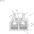
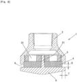
- Fig.1 is showing the first embodiment of the injection head for liquid fire extinguishing agent of the present invention.
- This injection head for liquid fire extinguishing agent 1 is, in a fire extinguishing equipment using liquid fire extinguishing agent, arranged for releasing a liquid fire extinguishing agent to a fire extinguishing area;
- the injection head 1 is comprising of an injection head body 2 connecting with a pipe (not shown) providing the liquid fire extinguishing agent, an orifice plate 3 arranged in the injection head body 2 and formed with an orifice 31 through which flowing the liquid fire extinguishing agent and, a porous member 4 having a block shape arranged in an exiting part of the orifice 31 and, a baffle plate 5 arranged contacting with an end surface of the porous member 4 opposite side of the exiting part of the orifice 31, and the baffle plate 5 covers at least a projected area of a circumscribed circle 31c of the orifice 31 of the end surface of the porous member 4 and, the liquid fire extinguishing agent is released via a gap 6 formed between the injection head body 2 and
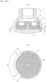
- the injection head1 is formed in a round shape having rotational symmetry around a central axis.
- a female thread (or a male thread) for connecting the pipe is formed in the injection head body 2 for connecting the pipe providing the liquid fire extinguishing agent.
- the orifice plate 3 has a disk shape that is formed by placing one or more orifices 31 (6 pieces in the present embodiment.) in equiangular spacing in the center, the orifice plate 3 is detachable arranged on a step part 21 formed in an interior space of the injection head body 2, for example, via threads formed on peripheral surfaces of the step part 21 and the orifice plate 3.
- the orifice plate 3 formed with a plurality of types of orifices 31 can be selected according to the conditions such as installation location.
- the porous member 4 having a block shape is composed of an integrated structure, as well as, as the present embodiment, the porous member 4 can be composed of a divided structure, laminated a plurality of porous members 41, 42.
- the porous member 4 having block shape it can be preferably used materials having high shape retention performance, that is inorganic materials (metal, metal oxide, metal hydroxide etc.) no deformation by a release pressure of the liquid fire extinguishing agent, and can be used more preferably porous metal material (Cermet (Registered tradename), made by Sumitomo Electric Industries) comprising 3 dimensional reticulated structure.
- inorganic materials metal, metal oxide, metal hydroxide etc.
- porous metal material Cermet (Registered tradename), made by Sumitomo Electric Industries
- the pore diameter of pores in the porous material 4 composes the whole body with homogeneous material, as well as the whole body can be composed of material that a pore diameter of pores changed gradually smaller in the flowing direction of the liquid fire extinguishing agent, for example, in the present embodiment, it can be composed of material smaller in a pore diameter of pores in a porous member 42 of downstream side of the liquid fire extinguishing agent member than a pore diameter of pores in a porous member 41 of upstream side.
- the liquid fire extinguishing agent flowing in the porous member having block shape can be uniformly diffused.
- the porous member 4 is arranged on an exiting part of the orifice 31.
- the baffle plate 5 is arranged in contact with an end face of another side of the porous member 4, that is an end face of the opposite side of the exiting part of the orifice 31 of the porous member 4.
- the orifice plate 3 and the porous member 4 have one-step structure, but like a modified embodiment shown in Fig.2 , they can be 2 step structure (or a multistage structure comprising 3 or more steps) by arranging an orifice plate 3A, formed with an orifice 31A, and a porous member 4A in the upstream sides of the orifice plate 3 and the porous member 4.
- the orifice plate3 A is composed detachably in the injection head body 2 via an opening of a connection side of the injection head body 2 for connecting to the pipe (The orifice plates 3 of embodiments shown in Fig.6 , Fig.9 , Fig.11 , Fig.14 and Fig.15 are the same.).
- the porous member 4 is assembled to the injection head body 2 and is preserved as stock, and when shipping it, the orifice plate 3A (The orifice plate 3) corresponding to the flow rate of the liquid fire extinguishing agent released from the injection head can be mounted to the injection head body 2 via the opening of the connection side of the injection head body 2 for that connecting to the pipe.
- the injection heads of these embodiments that become upsizing comparing to general injection heads are easy to preserve as stock and, while solving problems that are restrictions of storage locations, cost increasing etc., the shipment of the injection head can be speedily performed.
- the thread part 51 is formed integrating to the baffle plate 5, and as well as, like a modified embodiment shown in Fig.3 , it can be composed of another members (The thread members 8). Also, when the thread part 51 is composed of the thread member 8, 1 or more thread members 8 can be used.) penetrating a central part of the porous member 4 to the orifice plate 3 (or the thread part 51 is composed of a bold and a nut and is fastened to the orifice plate 3), the baffle plate 5 is fixed to the injection head body 2.
- the baffle plate 5 by contacting the baffle plate 5 with the end surface of another side of the porous member 4, it covers at least a projected area of a circumscribed circle 31c of the end surface of the porous member4 (In the present embodiment, 6 pieces of the common circumscribed circles 31c of the orifice 31), and hence the liquid fire extinguishing agent does not release from this part and, the liquid fire extinguishing agent is released via the gap 6 formed between the injection head body 2 and the baffle plate 5.
- the gap 6 formed between the injection head body 2 and the baffle plate 5 is composed of slits having torus shape with an outlet side slightly expanded, and hence release form of the liquid fire extinguishing agent can be a cylindrical shape in the same direction as the axial direction of the orifice 31 (The axial direction of the central axis of the injection head body 2).
- the width dimension D of the gap 6 comprising slits having torus shapes can be properly set according to the capacity of the injection head for liquid fire extinguishing agent 1 or a liquid fire extinguishing agent that is a subject, but it is set preferably 30 mm or less, more preferably 1 mm to about 10 mm and, is set as being the ratio of a inner diameter to a outer diameter of the gap 6 0.70 or more.
- a dimension T in the thickness direction of the gap 6 comprising of slits having torus shapes can be arranged preferably 30 mm or less, more preferably 1 mm to 10 mm, so as to be able limiting the releasing direction of the liquid fire extinguishing agent in a specific direction.
- the diffusion characteristic in the same direction as the axial direction (An axial direction of the central axis of the injection head body 2) of the orifice 31 of the liquid fire extinguishing agent can be improved.
- the liquid fire extinguishing agent provided through the orifice 31 diffuses while flowing inside the porous member 4 having block shape without short path and, release direction of the liquid fire extinguishing agent is limited in a specific direction by the baffle plate 5, and hence diffusion characteristics and vaporization characteristics of the liquid fire extinguishing agent are improved and, the liquid fire extinguishing agent can be sprayed and vaporized in a wide scope. As a result, the fire extinguishing scope that can cover by one injection head 1 can be enlarged.
- liquid fire extinguishing agent is diffusing while flowing inside the porous member 4 having block shape without shot path and released, a noise generated during releasing the liquid fire extinguishing agent can be reduced.
- the gap 6 formed between the injection head body 2 and the baffle plate 5 is composed of slits having torus shapes with slightly expanded outlet side, but a shape of the gap 6, not limited, is composed of slits having torus shapes having a straight outlet side that is without expanded, and hence diffusion characteristics in the direction as the same as the axial direction of the orifice 31 of the liquid fire extinguishing agent (The axial direction of the central axis of the injection head body 2) are improved and, the liquid fire extinguishing agent can be sprayed and vaporized in more wide scope.
- the baffle plate 5 side is composed of slits having torus shapes that largely expanded than the first embodiment, and hence the diffusion characteristics to the center direction of the liquid fire extinguishing agent releasing in torus shape can be improved.
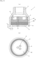
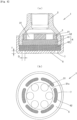
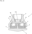
- the baffle plate 5 is fastened to the injection head body 2 by screwing the thread part 51 penetrating the central part of the porous member 4 to the orifice plate 3, but like modified embodiments shown in Fig.5 and Fig.6 , the baffle plate 5 has a cap structure having a rising part 52 and, can be fastened by screwing to the injection head body 2.
- the through hole 7 is comprising of oblong holes (a modified embodiment shown in Fig.5 ) or round holes (a modified embodiment shown in Fig.6 ) that are arranged in torus shape, and hence release form of the liquid fire extinguishing agent can be a cylindrical shape in the same direction as the axial direction of the orifice 31 (The axial direction of the central axis of the injection head body 2).
- the width dimension D and a formation interval of the through hole 7 can be properly set according to the capacity of the injection head for liquid fire extinguishing agent 1 or the liquid fire extinguishing agent which is the subject, but the dimension D of the through hole 7 is set preferably 30 mm or less, more preferably 1 mm to about 10 mm and, it is set as being the ratio of a diameter of the small-diameter circle 71 to a diameter of the large-diameter circle 72 contacting commonly with a plurality of through holes 7 0.70 or more.
- the dimension T in the thickness direction of the through hole 7 can be set preferably 30 mm or less, more preferably 1 mm to about 10 mm, so as to be able limiting the releasing direction of the liquid fire extinguishing agent in a specific direction.
- the diffusion characteristic in the same direction as the axial direction (An axial direction of the central axis of the injection head body 2) of the orifice 31 of the liquid fire extinguishing agent can be improved.
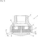
- the release form of the liquid fire extinguishing agent is the cylindrical shape in the same direction as the axial direction of the orifice 31 (The axial direction of the center direction of the injection head body 2), but for example, like the second embodiment of the injection head for liquid fire extinguishing agent not according to the present invention shown in Fig.7 , not limited, notches 22, 53 are formed by cutting conically the injection head body 2 and the baffle plate 5 that are located in the gap 6, and hence a release form of the liquid fire extinguishing agent has conical shape having predetermined angle to the axial direction of the orifice 31(In the present embodiment, it sets about 65°, but this angle can be set arbitrary angle of 0 to 90°).
- the width dimension of the gap 6 comprising slits having torus shapes can be properly set according to the capacity of the injection head for liquid fire extinguishing agent 1 or the liquid fire extinguishing agent which is the subject, but it is set preferably 30mm or less, more preferably 1 mm to about 10 mm.
- the diffusion characteristics in the same direction as the axial direction of the orifice 31 of the liquid fire extinguishing agent can be improved, and further, by providing a diffusion characteristics in the directional component orthogonal to the axial direction of the orifice31 of the liquid fire extinguishing agent, the liquid fire extinguishing agent can be sprayed and vaporized in more wide scope.
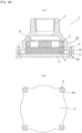
- the release form of the liquid fire extinguishing agent like the third embodiment of the injection head for liquid fire extinguishing agent not according to the present invention shown in Fig.8 , by arranging the gap 6 in a lower end side of the injection head body 2, the release form of the liquid fire extinguishing agent can be having a disk shape in the direction orthogonal to the axial direction of the orifice 31.
- the width dimension of the gap 6 comprising slits having torus shapes can be properly set according to the capacity of the injection head for liquid fire extinguishing agent 1 or the liquid fire extinguishing agent which is the subject, but it is set preferably 30mm or less, more preferably 1 mm to about 10 mm.
- a dimension T in the thickness direction of the gap 6 comprising of slits having torus shapes can be arranged preferably 30 mm or less, more preferably 1 mm to about 10 mm, so as to be able limiting the releasing direction of the liquid fire extinguishing agent in a specific direction.
- the liquid fire extinguishing agent can be sprayed and vaporized in more wide scope.
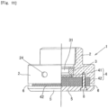
- the orifice plate 3 and the porous member4 have one-step structure, but like a modified embodiment shown in Fig.9 , they can be 2 step structure (or a multistage structure comprising 3 or more steps) by arranging an orifice plate 3A, formed with an orifice 31A, and a porous member 4A in the upstream sides of the orifice plate 3 and the porous member 4.
- the baffle plate5 is screwed to the orifice plate 3 by the thread part 51 penetrating the center part of the porous member 4, but instead of this, the injection head body 2 and the baffle plate 5 can be fastened by using thread member 8.
- bulging parts 23, 54 protruding partially are formed in outer peripheral sides of the injection head body 2 and the baffle plate 5, the injection head body 2 and the baffle plate 5 can be fastened by using the thread member 8 on the location of these bulging parts 23, 54.
- an operation hole 24 is formed in the outer peripheral surface of the injection head body 2 for mounting a fastening tool (not shown).
- the release form of the liquid fire extinguishing agent has a fan shape having a predetermined angle a in the direction orthogonal to the axial direction of the orifice 31.
- This release form of the liquid fire extinguishing agent can be easy obtained by closing a part of the gap 6 by a closing member 62 in which the gap 6 is formed between the injection head body 2 and the baffle plate 5 and comprising slits having a torus shape releasing the liquid fire extinguishing agent.
- the angle a can be set at an arbitrary angle (For example, in a scope of 30° to 330°) according to such as an arranging form of the injection head 1.
- the liquid fire extinguishing agent can be sprayed in a specific direction and vaporized, and hence for example, it can be preferably used for the injection head 1 arranged in an internal corner part of a room constituting a fire extinguishing area.
- the orifice 31 that arranged in equiangular spacing can be arranged in nonuniform distribution.
- a partition wall (An end surface 62a of a closing member 62) for making a release form of the liquid fire extinguishing agent a fan shape and that forms both ends of the gap 6 formed between the injection head body 2 and the baffle plate 5 is arranged on an inclined surface facing to the opposite side (Deep side) of the gap 6 and, the gap 6 having a wedge shape is formed between this inclined surface (The end surface 62a of the closing member 62) and the outer peripheral surface of the porous member 4.
- the inclined surface (The end surface 62a of the closing member 62) is formed preferably in a shape circumscribing an outer peripheral surface of the porous member 4.
- a shape of the inclined surface (The end surface 62a of the closing member 62) is no limited to plane shapes of the modified embodiments shown in Fig.13-1 and Fig.13-2 , and can be curved shapes, like modified embodiments shown in Fig.13-2(b) to (e) .
- the end surface 62a of the closing member 62 is processed so as to that in Fig.13-2(b) illustrated a semicircular opening as open, in Fig.13-2(c) illustrated a semicircular opening smaller than the beforementioned semicircular opening as open, in Fig.13-2(d) illustrated a 1 ⁇ 4 circular opening as open, in Fig.13-2(e) a circular opening as open.
- the end surface 62a of the closing member 62 is processed so as that a semicircular opening illustrated in Fig.13-2(b) as open, a semicircular opening smaller than the beforementioned semicircular opening illustrated in Fig.13-2(c) as open, a 1 ⁇ 4 circular opening illustrated in Fig.13-2(d) as open and, a circular opening illustrated in Fig.13-2(e) as open.
- the liquid fire extinguishing agent can be released via the through hole 7 formed outside of the projected area of the circumscribed circle of the orifice 31 (In the present embodiment, 6 pieces of the common circumscriber circles of orifice 31).
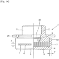
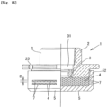
- the through hole 7 has oblong holes, like a modified embodiment shown in Fig.14 , arranged in torus shape on the rising part 52 of the baffle plate 5 that is a cap structure having the rising part 52; long holes, like a modified embodiment shown in Fig.15 , arranged a plurality of steps in torus shape in the rising part 52 of the baffle plate 5 that is a cap structure having a rising part 52 (In the embodiment shown, 2 steps.
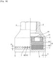
- round holes like a modified embodiment shown in Fig.16 , arranged in torus shape formed in a lower part of the injection head body 2 (A part arranged in the downward and facing the outer peripheral surface of the porous member 42.).
- the width dimension D and the formation interval of the through hole 7 can be properly set according to the capacity of the injection head for liquid fire extinguishing agent 1 or the liquid fire extinguishing agent which is the subject, but the dimension D of the through hole 7 is set preferably 30 mm or less, more preferably 1 mm to about 10 mm.
- the dimension T in the thickness direction of the through hole 7 (The rising part 52 of the baffle plate 5 or the injection head body 2) can be set preferably 30 mm or less, more preferably 1 mm to about 10 mm, so as to be able limiting the releasing direction of the liquid fire extinguishing agent in a specific direction.
- the liquid fire extinguishing agent can be sprayed and vaporized in more wide scope.
- a direction to release the liquid fire extinguishing agent is set in one direction, but by combination of each above mentioned embodiment, it can be made two direction to release the liquid fire extinguishing agent.
- the liquid fire extinguishing agent is released in cylindrical shape in the same direction as the axial direction of the orifice 31 (The axial direction of the central axis of the injection head body 2) from the gap 6 formed between the injection head body 2 and the baffle plate 5, and as well as is released in disk shape in the direction orthogonal to the axial direction of the orifice 31 from the through hole 7 composing of around holes arranged in torus shape arranged in the lower part of the injection head body 2 (A part arranged in the downward and facing the outer peripheral surface of the porous member 42.).
- the diffusion characteristics in the direction as the same direction or orthogonal to the axial direction of the orifice 31 of the liquid fire extinguishing agent is improved and, the liquid fire extinguishing agent can be sprayed and vaporized in more wide scope.
- the injection head for liquid fire extinguishing agent of the present invention has good diffusion characteristics and vaporization characteristics of liquid fire extinguishing agent, can be enlarge the fire extinguishing scope covering by one injection head and, can enhance reduction efficiency of noise; and hence in the fire extinguishing equipment using liquid fire extinguishing agent, it can be used in wide in the injection head set for releasing liquid fire extinguishing agent into a fire extinguishing area, the object for application is not limited fire extinguishing equipments newly set, but it can be applied to existing fire extinguishing equipments by exchanging only injection heads.
Landscapes
- Business, Economics & Management (AREA)
- Emergency Management (AREA)
- Health & Medical Sciences (AREA)
- Public Health (AREA)
- Nozzles (AREA)
- Fire-Extinguishing By Fire Departments, And Fire-Extinguishing Equipment And Control Thereof (AREA)
- Chemical & Material Sciences (AREA)
- Chemical Kinetics & Catalysis (AREA)
- General Chemical & Material Sciences (AREA)
- Fire-Extinguishing Compositions (AREA)
Priority Applications (1)
| Application Number | Priority Date | Filing Date | Title |
|---|---|---|---|
| EP23158146.3A EP4205818B1 (en) | 2018-10-02 | 2019-09-30 | Injection head for liquid fire extinguishing agent |
Applications Claiming Priority (2)
| Application Number | Priority Date | Filing Date | Title |
|---|---|---|---|
| JP2018187665 | 2018-10-02 | ||
| PCT/JP2019/038588 WO2020071329A1 (ja) | 2018-10-02 | 2019-09-30 | 液化消火剤用噴射ヘッド |
Related Child Applications (2)
| Application Number | Title | Priority Date | Filing Date |
|---|---|---|---|
| EP23158146.3A Division-Into EP4205818B1 (en) | 2018-10-02 | 2019-09-30 | Injection head for liquid fire extinguishing agent |
| EP23158146.3A Division EP4205818B1 (en) | 2018-10-02 | 2019-09-30 | Injection head for liquid fire extinguishing agent |
Publications (4)
| Publication Number | Publication Date |
|---|---|
| EP3815752A1 EP3815752A1 (en) | 2021-05-05 |
| EP3815752A4 EP3815752A4 (en) | 2022-02-09 |
| EP3815752B1 true EP3815752B1 (en) | 2023-06-07 |
| EP3815752C0 EP3815752C0 (en) | 2023-06-07 |
Family
ID=70055552
Family Applications (2)
| Application Number | Title | Priority Date | Filing Date |
|---|---|---|---|
| EP19869477.0A Active EP3815752B1 (en) | 2018-10-02 | 2019-09-30 | Injection head for liquid fire extinguishing agent |
| EP23158146.3A Active EP4205818B1 (en) | 2018-10-02 | 2019-09-30 | Injection head for liquid fire extinguishing agent |
Family Applications After (1)
| Application Number | Title | Priority Date | Filing Date |
|---|---|---|---|
| EP23158146.3A Active EP4205818B1 (en) | 2018-10-02 | 2019-09-30 | Injection head for liquid fire extinguishing agent |
Country Status (11)
| Country | Link |
|---|---|
| US (1) | US11369978B2 (enExample) |
| EP (2) | EP3815752B1 (enExample) |
| JP (1) | JP7299629B2 (enExample) |
| KR (1) | KR102755691B1 (enExample) |
| CN (1) | CN112312975B (enExample) |
| ES (2) | ES2973997T3 (enExample) |
| MY (1) | MY205571A (enExample) |
| PH (1) | PH12020552242A1 (enExample) |
| SG (1) | SG11202012389XA (enExample) |
| TW (1) | TWI799647B (enExample) |
| WO (1) | WO2020071329A1 (enExample) |
Families Citing this family (6)
| Publication number | Priority date | Publication date | Assignee | Title |
|---|---|---|---|---|
| US11060460B1 (en) * | 2019-04-01 | 2021-07-13 | Marine Turbine Technologies, LLC | Fuel distribution system for gas turbine engine |
| EP4096797B1 (en) * | 2020-01-31 | 2024-10-30 | Kidde-Fenwal, LLC | Low noise discharge nozzle |
| CN112206448A (zh) * | 2020-09-23 | 2021-01-12 | 诸佳枫 | 一种在喷水时可最大程度减少噪音的喷水枪头 |
| US20230293921A1 (en) * | 2022-03-21 | 2023-09-21 | Carrier Corporation | Low noise nozzle assembly for fire suppression system |
| WO2024257508A1 (ja) * | 2023-06-13 | 2024-12-19 | 株式会社コーアツ | ガス系消火設備用の消音手段を備えた噴射ヘッド |
| US20250303208A1 (en) * | 2024-03-29 | 2025-10-02 | The Reliable Automatic Sprinkler Co. Inc. | Foam-water fire sprinkler |
Family Cites Families (20)
| Publication number | Priority date | Publication date | Assignee | Title |
|---|---|---|---|---|
| US3022014A (en) * | 1958-11-12 | 1962-02-20 | Stephen A Young | Shower head |
| JPS543036Y2 (enExample) * | 1976-06-07 | 1979-02-09 | ||
| US5404957A (en) * | 1993-10-18 | 1995-04-11 | Mccormack; Pat | Fire retardant foam generator |
| IT1317475B1 (it) * | 2000-05-05 | 2003-07-09 | Vesta S R L | Ugello silenziato per la scarica di gas estinguenti. |
| US6763894B2 (en) * | 2001-08-01 | 2004-07-20 | Kidde-Fenwal, Inc. | Clean agent fire suppression system and rapid atomizing nozzle in the same |
| US20050001065A1 (en) * | 2001-08-01 | 2005-01-06 | Kidde-Fenwal, Inc. | Nozzle apparatus and method for atomizing fluids |
| CN200951280Y (zh) * | 2006-09-06 | 2007-09-26 | 南京消防器材股份有限公司 | 低压二氧化碳灭火系统专用喷头 |
| GB2478104B (en) * | 2008-12-18 | 2012-10-03 | Utc Fire & Security Corp | Atomizing nozzle for a fire suppression system |
| CN102413878B (zh) * | 2009-04-27 | 2013-07-24 | 报知机股份有限公司 | 防火设备 |
| JP5276630B2 (ja) * | 2009-10-23 | 2013-08-28 | エア・ウォーター防災株式会社 | ガス消火設備 |
| JP5972518B2 (ja) * | 2009-11-02 | 2016-08-17 | 株式会社コーアツ | ガス系消火設備用の消音機能を有する噴射ヘッド |
| JP5452193B2 (ja) * | 2009-12-02 | 2014-03-26 | 株式会社Nttファシリティーズ | 整流筒及びこれを備えたガス消火システム |
| TWI566804B (zh) * | 2012-02-21 | 2017-01-21 | 高壓股份有限公司 | 氣體系滅火設備用的具有消音功能的噴射頭 |
| JP5276730B1 (ja) * | 2012-03-21 | 2013-08-28 | 株式会社コーアツ | ガス系消火設備用の消音機能を有する噴射ヘッド |
| US9597537B2 (en) * | 2012-05-03 | 2017-03-21 | Koatsu Co., Ltd. | Injection head having silencing function for gas type fire extinguisher |
| JP6196955B2 (ja) * | 2013-10-02 | 2017-09-13 | エア・ウォーター防災株式会社 | 消火ガス噴射装置およびそれを備えたガス消火装置 |
| CN107847776A (zh) * | 2015-12-04 | 2018-03-27 | 泰科消防产品有限合伙公司 | 用于惰性气体排出系统的低压降声抑制器喷嘴 |
| US20200353300A1 (en) * | 2016-12-26 | 2020-11-12 | Koatsu Co., Ltd. | Injection head having silencing function for gas-type fire extinguisher and method for storing and assembling thereof |
| CN106861101A (zh) * | 2017-04-11 | 2017-06-20 | 广州广消阀门有限公司 | 一种氟化酮气体灭火装置 |
| KR102624816B1 (ko) * | 2017-05-19 | 2024-01-15 | 가부시키가이샤 고아츠 | 액화 소화제용 분사 헤드 |
-
2019
- 2019-09-20 TW TW108133940A patent/TWI799647B/zh active
- 2019-09-30 JP JP2020550429A patent/JP7299629B2/ja active Active
- 2019-09-30 US US17/251,540 patent/US11369978B2/en active Active
- 2019-09-30 WO PCT/JP2019/038588 patent/WO2020071329A1/ja not_active Ceased
- 2019-09-30 EP EP19869477.0A patent/EP3815752B1/en active Active
- 2019-09-30 ES ES23158146T patent/ES2973997T3/es active Active
- 2019-09-30 CN CN201980042481.3A patent/CN112312975B/zh active Active
- 2019-09-30 EP EP23158146.3A patent/EP4205818B1/en active Active
- 2019-09-30 KR KR1020207035922A patent/KR102755691B1/ko active Active
- 2019-09-30 SG SG11202012389XA patent/SG11202012389XA/en unknown
- 2019-09-30 ES ES19869477T patent/ES2947441T3/es active Active
- 2019-09-30 MY MYPI2020006578A patent/MY205571A/en unknown
-
2020
- 2020-12-21 PH PH12020552242A patent/PH12020552242A1/en unknown
Also Published As
| Publication number | Publication date |
|---|---|
| EP4205818C0 (en) | 2024-02-14 |
| CN112312975A (zh) | 2021-02-02 |
| ES2973997T3 (es) | 2024-06-25 |
| CA3104466A1 (en) | 2020-04-09 |
| KR102755691B1 (ko) | 2025-01-20 |
| CN112312975B (zh) | 2022-10-18 |
| WO2020071329A1 (ja) | 2020-04-09 |
| US11369978B2 (en) | 2022-06-28 |
| EP3815752C0 (en) | 2023-06-07 |
| MY205571A (en) | 2024-10-26 |
| EP3815752A1 (en) | 2021-05-05 |
| EP4205818B1 (en) | 2024-02-14 |
| PH12020552242A1 (en) | 2021-06-28 |
| TW202026040A (zh) | 2020-07-16 |
| KR20210063278A (ko) | 2021-06-01 |
| SG11202012389XA (en) | 2021-01-28 |
| JP7299629B2 (ja) | 2023-06-28 |
| EP4205818A1 (en) | 2023-07-05 |
| TWI799647B (zh) | 2023-04-21 |
| JPWO2020071329A1 (ja) | 2021-09-16 |
| ES2947441T3 (es) | 2023-08-09 |
| US20210252530A1 (en) | 2021-08-19 |
| EP3815752A4 (en) | 2022-02-09 |
Similar Documents
| Publication | Publication Date | Title |
|---|---|---|
| EP3815752B1 (en) | Injection head for liquid fire extinguishing agent | |
| JP6363318B1 (ja) | ガス系消火設備用の消音機能を有する噴射ヘッド及びその保管・組立方法 | |
| CN217773041U (zh) | 水平侧壁窗口喷洒器和用于保护窗装置的窗口喷洒器系统 | |
| KR20170026443A (ko) | 미분무수 화재 진압 디바이스 및 제조 방법 | |
| JPWO2020071329A5 (enExample) | ||
| CA3104466C (en) | Injection head for liquid fire extinguishing agent | |
| JP7031829B2 (ja) | 液化消火剤用噴射ヘッド | |
| CA3029714A1 (en) | End cap agent nozzle | |
| KR102196055B1 (ko) | 노즐 및 격리판 | |
| RU2786611C2 (ru) | Распылительная головка для жидкого огнетушащего вещества | |
| JP7669013B1 (ja) | ガス系消火設備用の消音手段を備えた噴射ヘッド | |
| EP4010088A1 (en) | Fire suppression nozzles and systems | |
| JPH0716530B2 (ja) | 消火用泡ヘッド | |
| EP3740290B1 (en) | Silenced head for fire extinguishing gas discharge |
Legal Events
| Date | Code | Title | Description |
|---|---|---|---|
| STAA | Information on the status of an ep patent application or granted ep patent |
Free format text: STATUS: THE INTERNATIONAL PUBLICATION HAS BEEN MADE |
|
| PUAI | Public reference made under article 153(3) epc to a published international application that has entered the european phase |
Free format text: ORIGINAL CODE: 0009012 |
|
| STAA | Information on the status of an ep patent application or granted ep patent |
Free format text: STATUS: REQUEST FOR EXAMINATION WAS MADE |
|
| 17P | Request for examination filed |
Effective date: 20201202 |
|
| AK | Designated contracting states |
Kind code of ref document: A1 Designated state(s): AL AT BE BG CH CY CZ DE DK EE ES FI FR GB GR HR HU IE IS IT LI LT LU LV MC MK MT NL NO PL PT RO RS SE SI SK SM TR |
|
| DAV | Request for validation of the european patent (deleted) | ||
| DAX | Request for extension of the european patent (deleted) | ||
| A4 | Supplementary search report drawn up and despatched |
Effective date: 20220110 |
|
| RIC1 | Information provided on ipc code assigned before grant |
Ipc: B05B 1/26 20060101ALN20220103BHEP Ipc: A62C 99/00 20100101ALN20220103BHEP Ipc: B05B 1/14 20060101ALI20220103BHEP Ipc: A62C 31/05 20060101ALI20220103BHEP Ipc: B05B 1/00 20060101ALI20220103BHEP Ipc: A62C 31/02 20060101AFI20220103BHEP |
|
| GRAP | Despatch of communication of intention to grant a patent |
Free format text: ORIGINAL CODE: EPIDOSNIGR1 |
|
| STAA | Information on the status of an ep patent application or granted ep patent |
Free format text: STATUS: GRANT OF PATENT IS INTENDED |
|
| RIC1 | Information provided on ipc code assigned before grant |
Ipc: B05B 1/26 20060101ALN20221221BHEP Ipc: A62C 99/00 20100101ALN20221221BHEP Ipc: B05B 1/14 20060101ALI20221221BHEP Ipc: A62C 31/05 20060101ALI20221221BHEP Ipc: B05B 1/00 20060101ALI20221221BHEP Ipc: A62C 31/02 20060101AFI20221221BHEP |
|
| INTG | Intention to grant announced |
Effective date: 20230112 |
|
| GRAS | Grant fee paid |
Free format text: ORIGINAL CODE: EPIDOSNIGR3 |
|
| GRAA | (expected) grant |
Free format text: ORIGINAL CODE: 0009210 |
|
| STAA | Information on the status of an ep patent application or granted ep patent |
Free format text: STATUS: THE PATENT HAS BEEN GRANTED |
|
| AK | Designated contracting states |
Kind code of ref document: B1 Designated state(s): AL AT BE BG CH CY CZ DE DK EE ES FI FR GB GR HR HU IE IS IT LI LT LU LV MC MK MT NL NO PL PT RO RS SE SI SK SM TR |
|
| REG | Reference to a national code |
Ref country code: GB Ref legal event code: FG4D |
|
| REG | Reference to a national code |
Ref country code: CH Ref legal event code: EP Ref country code: AT Ref legal event code: REF Ref document number: 1573188 Country of ref document: AT Kind code of ref document: T Effective date: 20230615 |
|
| REG | Reference to a national code |
Ref country code: DE Ref legal event code: R096 Ref document number: 602019030770 Country of ref document: DE |
|
| U01 | Request for unitary effect filed |
Effective date: 20230626 |
|
| U07 | Unitary effect registered |
Designated state(s): AT BE BG DE DK EE FI FR IT LT LU LV MT NL PT SE SI Effective date: 20230630 |
|
| REG | Reference to a national code |
Ref country code: ES Ref legal event code: FG2A Ref document number: 2947441 Country of ref document: ES Kind code of ref document: T3 Effective date: 20230809 |
|
| REG | Reference to a national code |
Ref country code: LT Ref legal event code: MG9D |
|
| U20 | Renewal fee for the european patent with unitary effect paid |
Year of fee payment: 5 Effective date: 20230830 |
|
| PG25 | Lapsed in a contracting state [announced via postgrant information from national office to epo] |
Ref country code: NO Free format text: LAPSE BECAUSE OF FAILURE TO SUBMIT A TRANSLATION OF THE DESCRIPTION OR TO PAY THE FEE WITHIN THE PRESCRIBED TIME-LIMIT Effective date: 20230907 |
|
| PG25 | Lapsed in a contracting state [announced via postgrant information from national office to epo] |
Ref country code: RS Free format text: LAPSE BECAUSE OF FAILURE TO SUBMIT A TRANSLATION OF THE DESCRIPTION OR TO PAY THE FEE WITHIN THE PRESCRIBED TIME-LIMIT Effective date: 20230607 Ref country code: HR Free format text: LAPSE BECAUSE OF FAILURE TO SUBMIT A TRANSLATION OF THE DESCRIPTION OR TO PAY THE FEE WITHIN THE PRESCRIBED TIME-LIMIT Effective date: 20230607 Ref country code: GR Free format text: LAPSE BECAUSE OF FAILURE TO SUBMIT A TRANSLATION OF THE DESCRIPTION OR TO PAY THE FEE WITHIN THE PRESCRIBED TIME-LIMIT Effective date: 20230908 |
|
| PG25 | Lapsed in a contracting state [announced via postgrant information from national office to epo] |
Ref country code: SK Free format text: LAPSE BECAUSE OF FAILURE TO SUBMIT A TRANSLATION OF THE DESCRIPTION OR TO PAY THE FEE WITHIN THE PRESCRIBED TIME-LIMIT Effective date: 20230607 |
|
| PG25 | Lapsed in a contracting state [announced via postgrant information from national office to epo] |
Ref country code: IS Free format text: LAPSE BECAUSE OF FAILURE TO SUBMIT A TRANSLATION OF THE DESCRIPTION OR TO PAY THE FEE WITHIN THE PRESCRIBED TIME-LIMIT Effective date: 20231007 |
|
| PG25 | Lapsed in a contracting state [announced via postgrant information from national office to epo] |
Ref country code: SM Free format text: LAPSE BECAUSE OF FAILURE TO SUBMIT A TRANSLATION OF THE DESCRIPTION OR TO PAY THE FEE WITHIN THE PRESCRIBED TIME-LIMIT Effective date: 20230607 Ref country code: SK Free format text: LAPSE BECAUSE OF FAILURE TO SUBMIT A TRANSLATION OF THE DESCRIPTION OR TO PAY THE FEE WITHIN THE PRESCRIBED TIME-LIMIT Effective date: 20230607 Ref country code: RO Free format text: LAPSE BECAUSE OF FAILURE TO SUBMIT A TRANSLATION OF THE DESCRIPTION OR TO PAY THE FEE WITHIN THE PRESCRIBED TIME-LIMIT Effective date: 20230607 Ref country code: IS Free format text: LAPSE BECAUSE OF FAILURE TO SUBMIT A TRANSLATION OF THE DESCRIPTION OR TO PAY THE FEE WITHIN THE PRESCRIBED TIME-LIMIT Effective date: 20231007 Ref country code: CZ Free format text: LAPSE BECAUSE OF FAILURE TO SUBMIT A TRANSLATION OF THE DESCRIPTION OR TO PAY THE FEE WITHIN THE PRESCRIBED TIME-LIMIT Effective date: 20230607 |
|
| PG25 | Lapsed in a contracting state [announced via postgrant information from national office to epo] |
Ref country code: PL Free format text: LAPSE BECAUSE OF FAILURE TO SUBMIT A TRANSLATION OF THE DESCRIPTION OR TO PAY THE FEE WITHIN THE PRESCRIBED TIME-LIMIT Effective date: 20230607 |
|
| REG | Reference to a national code |
Ref country code: DE Ref legal event code: R097 Ref document number: 602019030770 Country of ref document: DE |
|
| PLBE | No opposition filed within time limit |
Free format text: ORIGINAL CODE: 0009261 |
|
| STAA | Information on the status of an ep patent application or granted ep patent |
Free format text: STATUS: NO OPPOSITION FILED WITHIN TIME LIMIT |
|
| 26N | No opposition filed |
Effective date: 20240308 |
|
| PG25 | Lapsed in a contracting state [announced via postgrant information from national office to epo] |
Ref country code: MC Free format text: LAPSE BECAUSE OF FAILURE TO SUBMIT A TRANSLATION OF THE DESCRIPTION OR TO PAY THE FEE WITHIN THE PRESCRIBED TIME-LIMIT Effective date: 20230607 |
|
| U20 | Renewal fee for the european patent with unitary effect paid |
Year of fee payment: 6 Effective date: 20240903 |
|
| PGFP | Annual fee paid to national office [announced via postgrant information from national office to epo] |
Ref country code: ES Payment date: 20241001 Year of fee payment: 6 |
|
| PGFP | Annual fee paid to national office [announced via postgrant information from national office to epo] |
Ref country code: CH Payment date: 20241001 Year of fee payment: 6 |
|
| PG25 | Lapsed in a contracting state [announced via postgrant information from national office to epo] |
Ref country code: CY Free format text: LAPSE BECAUSE OF FAILURE TO SUBMIT A TRANSLATION OF THE DESCRIPTION OR TO PAY THE FEE WITHIN THE PRESCRIBED TIME-LIMIT; INVALID AB INITIO Effective date: 20190930 |
|
| PG25 | Lapsed in a contracting state [announced via postgrant information from national office to epo] |
Ref country code: HU Free format text: LAPSE BECAUSE OF FAILURE TO SUBMIT A TRANSLATION OF THE DESCRIPTION OR TO PAY THE FEE WITHIN THE PRESCRIBED TIME-LIMIT; INVALID AB INITIO Effective date: 20190930 |
|
| REG | Reference to a national code |
Ref country code: CH Ref legal event code: U11 Free format text: ST27 STATUS EVENT CODE: U-0-0-U10-U11 (AS PROVIDED BY THE NATIONAL OFFICE) Effective date: 20251001 |
|
| U20 | Renewal fee for the european patent with unitary effect paid |
Year of fee payment: 7 Effective date: 20250828 |
|
| PGFP | Annual fee paid to national office [announced via postgrant information from national office to epo] |
Ref country code: TR Payment date: 20250829 Year of fee payment: 7 |
|
| PGFP | Annual fee paid to national office [announced via postgrant information from national office to epo] |
Ref country code: GB Payment date: 20250828 Year of fee payment: 7 |
|
| PGFP | Annual fee paid to national office [announced via postgrant information from national office to epo] |
Ref country code: IE Payment date: 20250923 Year of fee payment: 7 |