WO2020071329A1 - 液化消火剤用噴射ヘッド - Google Patents
液化消火剤用噴射ヘッドInfo
- Publication number
- WO2020071329A1 WO2020071329A1 PCT/JP2019/038588 JP2019038588W WO2020071329A1 WO 2020071329 A1 WO2020071329 A1 WO 2020071329A1 JP 2019038588 W JP2019038588 W JP 2019038588W WO 2020071329 A1 WO2020071329 A1 WO 2020071329A1
- Authority
- WO
- WIPO (PCT)
- Prior art keywords
- fire extinguishing
- extinguishing agent
- liquefied fire
- liquefied
- orifice
- Prior art date
- Legal status (The legal status is an assumption and is not a legal conclusion. Google has not performed a legal analysis and makes no representation as to the accuracy of the status listed.)
- Ceased
Links
Images


Classifications
-
- A—HUMAN NECESSITIES
- A62—LIFE-SAVING; FIRE-FIGHTING
- A62C—FIRE-FIGHTING
- A62C31/00—Delivery of fire-extinguishing material
- A62C31/02—Nozzles specially adapted for fire-extinguishing
- A62C31/05—Nozzles specially adapted for fire-extinguishing with two or more outlets
-
- B—PERFORMING OPERATIONS; TRANSPORTING
- B05—SPRAYING OR ATOMISING IN GENERAL; APPLYING FLUENT MATERIALS TO SURFACES, IN GENERAL
- B05B—SPRAYING APPARATUS; ATOMISING APPARATUS; NOZZLES
- B05B1/00—Nozzles, spray heads or other outlets, with or without auxiliary devices such as valves, heating means
- B05B1/34—Nozzles, spray heads or other outlets, with or without auxiliary devices such as valves, heating means designed to influence the nature of flow of the liquid or other fluent material, e.g. to produce swirl
-
- A—HUMAN NECESSITIES
- A62—LIFE-SAVING; FIRE-FIGHTING
- A62C—FIRE-FIGHTING
- A62C31/00—Delivery of fire-extinguishing material
- A62C31/02—Nozzles specially adapted for fire-extinguishing
-
- A—HUMAN NECESSITIES
- A62—LIFE-SAVING; FIRE-FIGHTING
- A62C—FIRE-FIGHTING
- A62C35/00—Permanently-installed equipment
- A62C35/58—Pipe-line systems
- A62C35/68—Details, e.g. of pipes or valve systems
-
- B—PERFORMING OPERATIONS; TRANSPORTING
- B05—SPRAYING OR ATOMISING IN GENERAL; APPLYING FLUENT MATERIALS TO SURFACES, IN GENERAL
- B05B—SPRAYING APPARATUS; ATOMISING APPARATUS; NOZZLES
- B05B1/00—Nozzles, spray heads or other outlets, with or without auxiliary devices such as valves, heating means
- B05B1/002—Nozzles, spray heads or other outlets, with or without auxiliary devices such as valves, heating means designed to reduce the generation or the transmission of noise or to produce a particular sound; associated with noise monitoring means
-
- B—PERFORMING OPERATIONS; TRANSPORTING
- B05—SPRAYING OR ATOMISING IN GENERAL; APPLYING FLUENT MATERIALS TO SURFACES, IN GENERAL
- B05B—SPRAYING APPARATUS; ATOMISING APPARATUS; NOZZLES
- B05B1/00—Nozzles, spray heads or other outlets, with or without auxiliary devices such as valves, heating means
- B05B1/02—Nozzles, spray heads or other outlets, with or without auxiliary devices such as valves, heating means designed to produce a jet, spray, or other discharge of particular shape or nature, e.g. in single drops, or having an outlet of particular shape
- B05B1/04—Nozzles, spray heads or other outlets, with or without auxiliary devices such as valves, heating means designed to produce a jet, spray, or other discharge of particular shape or nature, e.g. in single drops, or having an outlet of particular shape in flat form, e.g. fan-like, sheet-like
- B05B1/044—Slits, e.g. narrow openings defined by two straight and parallel lips; Elongated outlets for producing very wide discharges, e.g. fluid curtains
-
- B—PERFORMING OPERATIONS; TRANSPORTING
- B05—SPRAYING OR ATOMISING IN GENERAL; APPLYING FLUENT MATERIALS TO SURFACES, IN GENERAL
- B05B—SPRAYING APPARATUS; ATOMISING APPARATUS; NOZZLES
- B05B1/00—Nozzles, spray heads or other outlets, with or without auxiliary devices such as valves, heating means
- B05B1/02—Nozzles, spray heads or other outlets, with or without auxiliary devices such as valves, heating means designed to produce a jet, spray, or other discharge of particular shape or nature, e.g. in single drops, or having an outlet of particular shape
- B05B1/04—Nozzles, spray heads or other outlets, with or without auxiliary devices such as valves, heating means designed to produce a jet, spray, or other discharge of particular shape or nature, e.g. in single drops, or having an outlet of particular shape in flat form, e.g. fan-like, sheet-like
- B05B1/046—Outlets formed, e.g. cut, in the circumference of tubular or spherical elements
-
- B—PERFORMING OPERATIONS; TRANSPORTING
- B05—SPRAYING OR ATOMISING IN GENERAL; APPLYING FLUENT MATERIALS TO SURFACES, IN GENERAL
- B05B—SPRAYING APPARATUS; ATOMISING APPARATUS; NOZZLES
- B05B1/00—Nozzles, spray heads or other outlets, with or without auxiliary devices such as valves, heating means
- B05B1/14—Nozzles, spray heads or other outlets, with or without auxiliary devices such as valves, heating means with multiple outlet openings; with strainers in or outside the outlet opening
-
- B—PERFORMING OPERATIONS; TRANSPORTING
- B05—SPRAYING OR ATOMISING IN GENERAL; APPLYING FLUENT MATERIALS TO SURFACES, IN GENERAL
- B05B—SPRAYING APPARATUS; ATOMISING APPARATUS; NOZZLES
- B05B15/00—Details of spraying plant or spraying apparatus not otherwise provided for; Accessories
- B05B15/40—Filters located upstream of the spraying outlets
-
- A—HUMAN NECESSITIES
- A62—LIFE-SAVING; FIRE-FIGHTING
- A62C—FIRE-FIGHTING
- A62C99/00—Subject matter not provided for in other groups of this subclass
- A62C99/0009—Methods of extinguishing or preventing the spread of fire by cooling down or suffocating the flames
- A62C99/0018—Methods of extinguishing or preventing the spread of fire by cooling down or suffocating the flames using gases or vapours that do not support combustion, e.g. steam, carbon dioxide
-
- A—HUMAN NECESSITIES
- A62—LIFE-SAVING; FIRE-FIGHTING
- A62D—CHEMICAL MEANS FOR EXTINGUISHING FIRES OR FOR COMBATING OR PROTECTING AGAINST HARMFUL CHEMICAL AGENTS; CHEMICAL MATERIALS FOR USE IN BREATHING APPARATUS
- A62D1/00—Fire-extinguishing compositions; Use of chemical substances in extinguishing fires
- A62D1/0028—Liquid extinguishing substances
- A62D1/0057—Polyhaloalkanes
-
- B—PERFORMING OPERATIONS; TRANSPORTING
- B05—SPRAYING OR ATOMISING IN GENERAL; APPLYING FLUENT MATERIALS TO SURFACES, IN GENERAL
- B05B—SPRAYING APPARATUS; ATOMISING APPARATUS; NOZZLES
- B05B1/00—Nozzles, spray heads or other outlets, with or without auxiliary devices such as valves, heating means
- B05B1/26—Nozzles, spray heads or other outlets, with or without auxiliary devices such as valves, heating means with means for mechanically breaking-up or deflecting the jet after discharge, e.g. with fixed deflectors; Breaking-up the discharged liquid or other fluent material by impinging jets
- B05B1/262—Nozzles, spray heads or other outlets, with or without auxiliary devices such as valves, heating means with means for mechanically breaking-up or deflecting the jet after discharge, e.g. with fixed deflectors; Breaking-up the discharged liquid or other fluent material by impinging jets with fixed deflectors
- B05B1/265—Nozzles, spray heads or other outlets, with or without auxiliary devices such as valves, heating means with means for mechanically breaking-up or deflecting the jet after discharge, e.g. with fixed deflectors; Breaking-up the discharged liquid or other fluent material by impinging jets with fixed deflectors the liquid or other fluent material being symmetrically deflected about the axis of the nozzle
Definitions
- the present invention relates to an injection head for a liquefied fire extinguishing agent having a high boiling point such as a halide.
- a liquefied fire extinguishing agent having a high boiling point such as a halide, for example, dodecafluoro-2-methylpentan-3-one (CF 3 CF 2 C (O) CF (CF 3 ) 2 , boiling point 49) is used as a fire extinguishing agent.
- a halide for example, dodecafluoro-2-methylpentan-3-one
- FK-5-1-12 When using 2 ° C., NFPA / ISO registered name “FK-5-1-12”), use a spray head that sprays the liquefied fire extinguisher in a mist to discharge the liquefied fire extinguisher to the fire extinguishing target compartment. Like that.
- the spray head that sprays the liquefied fire extinguishing agent in the form of a mist has a problem that the diffusion characteristics and the vaporization characteristics of the liquefied fire extinguishing agent are poor, particularly the diffusion characteristics in the radiation axis direction, and the fire extinguishing target range that can be covered by one spray head is small.
- An object of the present invention is to provide a liquefied fire extinguisher jet head that can increase the range of fire extinguishing targets that can be covered by one jet head and can increase the noise reduction rate.
- a liquefied fire extinguishing agent jet head of the present invention is a jet head installed for discharging a liquefied fire extinguishing agent to a fire extinguishing target section in a fire extinguishing facility using a liquefied fire extinguishing agent,
- An injection head body to which a pipe for supplying the agent is connected an orifice plate formed on the injection head body, and having an orifice through which the liquefied fire extinguishing agent passes, and a block-shaped orifice disposed at the outlet of the orifice.
- the liquefied fire extinguishing agent can be discharged in a cylindrical shape in the same direction as the orifice.
- the liquefied fire extinguishing agent may be discharged in a conical shape having a predetermined angle with respect to the axial direction of the orifice.
- the discharge form of the liquefied fire extinguishing agent may be a disk shape in a direction perpendicular to the axial direction of the orifice.
- the liquefied fire extinguishing agent may be discharged in a fan shape having a predetermined angle in a direction perpendicular to the axial direction of the orifice.
- partition walls forming both ends of the gap formed between the injection head body and the baffle plate for making the discharge form of the liquefied fire extinguisher fan-shaped are formed on an inclined surface facing the opposite side of the gap.
- a wedge-shaped gap may be formed between the inclined surface and the porous member.
- the width dimension of the gap and / or the through hole is preferably 30 mm or less, more preferably 1 mm to 10 mm, or the ratio of the inner diameter to the outer diameter of the gap and / or The ratio of the diameter of the small diameter circle and the diameter of the large diameter circle that are in common contact can be set to 0.70 or more.
- the liquefied fire extinguishing agent supplied through the orifice diffuses while flowing through the block-shaped porous member without being short-passed, and is liquefied by the baffle plate.
- the diffusion characteristics and vaporization characteristics of the liquefied fire extinguishing agent can be improved, and the liquefied fire extinguishing agent can be diffused and vaporized over a wide range.
- the fire extinguishing target range that can be covered by one ejection head can be increased.
- the liquefied fire extinguishing agent flows and diffuses in the block-shaped porous member without being short-passed and is discharged, the noise generated when the liquefied fire extinguishing agent is discharged can be reduced.
- the diffusion characteristics of the liquefied fire extinguishing agent in the same direction as the axial direction of the orifice are improved, and Can be diffused and vaporized over a wider range.
- the diffusion characteristics of the liquefied fire extinguishing agent in the same direction as the axial direction of the orifice are improved.
- the liquefied fire extinguishing agent can be diffused and vaporized over a wider range by providing a diffusion characteristic of a component orthogonal to the axial direction of the orifice of the liquefied fire extinguishing agent.
- the diffusion characteristics of the liquefied fire extinguishing agent in the direction orthogonal to the axial direction of the orifice are improved, and The fire extinguisher can be diffused and vaporized over a wider range.
- the discharge form of the liquefied fire extinguishing agent fan-shaped having a predetermined angle in the direction orthogonal to the axial direction of the orifice, the diffusion characteristics of the liquefied fire extinguishing agent in the direction orthogonal to the axial direction of the orifice are improved.
- the liquefied fire extinguishing agent can be diffused and vaporized in a specific direction.
- partition walls forming both ends of the gap formed between the injection head body and the baffle plate for making the discharge form of the liquefied fire extinguisher fan-shaped are formed on an inclined surface facing the opposite side of the gap.
- the width dimension of the gap and / or the through hole is preferably 30 mm or less, more preferably 1 mm to 10 mm, or the ratio of the inner diameter to the outer diameter of the gap and / or The ratio of the diameter of the small diameter circle and the diameter of the large diameter circle that are in common contact can be set to 0.70 or more.
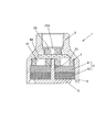
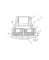
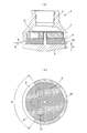
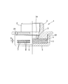
- FIG. 1 shows a first embodiment of a liquefied fire extinguishing agent jet head according to the present invention, wherein (a) is a front sectional view and (b) is a bottom view.
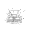
- FIG. 3 is a front sectional view showing a modified example of the first embodiment of the liquefied fire extinguishing agent jet head of the present invention.
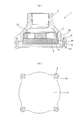
- the modified example of the first embodiment of the liquefied fire extinguishing agent jet head of the present invention is shown, wherein (a) is a front sectional view and (b) is a bottom view.
- FIG. 3 is a front sectional view showing a modified example of the first embodiment of the liquefied fire extinguishing agent jet head of the present invention.
- 3 shows a modified example of the first embodiment of the liquefied fire extinguishing agent jet head of the present invention, wherein (a) is a front sectional view and (b) is a bottom sectional view.
- 3 shows a modified example of the first embodiment of the liquefied fire extinguishing agent jet head of the present invention, wherein (a) is a front sectional view and (b) is a bottom sectional view. It is sectional drawing which shows 2nd Example of the injection head for liquefied fire extinguishing agents of this invention. It is sectional drawing which shows 3rd Example of the injection head for liquefied fire extinguishing agents of this invention.
- FIGS. 7A and 7B show a modified example of the third embodiment of the liquefied fire extinguishing agent jet head of the present invention, wherein FIG. 7A is a front sectional view, and FIG.
- FIGS. 7A and 7B show a modified example of the third embodiment of the liquefied fire extinguishing agent jet head of the present invention, wherein FIG. 7A is a front sectional view, and FIG. 7B is a sectional view taken along line AA of FIG.
- FIGS. 7A and 7B show a modified example of the third embodiment of the liquefied fire extinguishing agent jet head of the present invention, wherein FIG. 7A is a front sectional view, and FIG. 7B is a sectional view taken along line AA of FIG. FIGS.
- FIG. 13A and 13B show a modified example of the third embodiment of the liquefied fire extinguishing agent jet head according to the present invention, in which FIG. 13A is a sectional view taken along line BB of FIG. Sectional views corresponding to (a) of the modified embodiment, and (c) to (e) are explanatory views of closing members having different shapes. It is a front view (partial sectional view) showing the modification of the 3rd example of the jet head for liquefied fire extinguishing agents of the present invention. It is a front view (partial sectional view) showing the modification of the 3rd example of the jet head for liquefied fire extinguishing agents of the present invention.
- FIG. 4A is a front sectional view
- FIG. 4B is a front sectional view
- FIG. 1 shows a first embodiment of a liquefied fire extinguishing agent ejection head according to the present invention.
- the liquefied fire extinguishing agent injection head 1 is an injection head 1 that is installed in a fire extinguishing facility that uses liquefied fire extinguishing agent to discharge the liquefied fire extinguishing agent to a fire extinguishing target section. (Omitted), an orifice plate 3 provided with an orifice 31 through which the liquefied fire extinguisher passes, and a block shape provided at an outlet of the orifice 31. And a baffle plate 5 disposed in contact with an end face of the porous member 4 on the side opposite to the outlet of the orifice 31.
- the baffle plate 5 includes at least the porous member 4.
- the liquefied fire extinguishing agent passes through the gap 6 formed between the ejection head main body 2 and the baffle plate 5 while covering the projected area of the circumscribed circle 31c of the orifice 31 on the end face. So that release.
- the ejection head 1 is formed in a circular shape whose center axis is rotationally symmetric (the same applies to the following embodiments). Further, a female screw (or a male screw) for connecting the pipe is formed in the ejection head main body 2 to which the pipe for supplying the liquefied fire extinguishing agent is connected.
- the liquefied fire extinguishing agent targeted by the liquefied fire extinguishing agent jet head 1 includes the following fire extinguishing agents (1) to (3).
- dodecafluoro-2-methylpentan-3-one CF 3 CF 2 C (O) CF (CF 3 ) 2 , boiling point 49.2 ° C., NFPA / ISO Registered name "FK-5-1-12").
- the orifice plate 3 has a disk shape in which one or a plurality (six in the present embodiment) of orifices 31 are formed at equal angular intervals at the center.
- the step 21 is detachably disposed, for example, via a screw formed on the step 21 and the peripheral surface of the orifice plate 3.
- the orifice plate 3 having the plurality of types of orifices 31 formed therein can be selected according to conditions such as an installation location.
- the block-shaped porous member 4 may be formed of an integral structure, or may be formed of a divided structure in which a plurality of porous members 41 and 42 are stacked as shown in this embodiment.
- the block-shaped porous member 4 is preferably made of an inorganic material (metal, metal oxide, metal hydroxide, or the like) having high shape retention performance, that is, not causing deformation or the like due to the discharge pressure of the liquefied fire extinguisher.
- the porous metal material (“Celmet” (registered trademark) manufactured by Sumitomo Electric Industries, Ltd.) composed of a three-dimensional network can be more preferably used.
- the pore diameter of the voids of the porous member 4 is made of a homogeneous material, and the material is varied along the flow direction of the liquefied fire extinguishing agent. More specifically, the pore diameter of the voids is changed in the flow direction of the liquefied fire extinguishing agent. For example, in the present embodiment, the pore diameter of the pores of the porous member 41 on the upstream side in the flow direction of the liquefied fire extinguishing agent is smaller than that of the porous member 42 on the downstream side. It can be made of a material that reduces the pore size of the void.
- the liquefied fire extinguishing agent flowing in the block-shaped porous member can be uniformly diffused. Can be.
- one end face of the porous member 4 has the ejection head main body 2 (including the orifice plate 3 in the present embodiment. The same applies to the embodiment.), So that it is disposed at the outlet of the orifice 31.
- the baffle plate 5 is configured to abut on the other end surface of the porous member 4, that is, the end surface of the porous member 4 opposite to the outlet of the orifice 31.
- the orifice plate 3 and the porous member 4 have a single-stage structure.
- a two-stage structure or a multi-stage structure of three or more stages
- the orifice plate 3A is configured to be detachable from the ejection head main body 2 through an opening on the connection portion side of the ejection head main body 2 with the pipe (see later-described drawing). 6, 9, 11, 14, and 15).
- the porous member 4 is stored in stock in a state where the porous member 4 is assembled to the ejection head main body 2, and the orifice plate 3A (orifice plate 3) corresponding to the flow rate of the liquefied fire extinguishing agent discharged from the ejection head at the time of shipment.
- the baffle plate 5 is provided with a screw part 51 penetrating through the center of the porous member 4 (the screw part 51 is formed integrally with the baffle plate 5 and, as in the modified embodiment shown in FIG. In the case where the screw portion 51 is formed of the screw member 8, one or a plurality of screw members 8 can be used.)
- the screw portion 51 is formed of a bolt and a nut and fastened to the orifice plate 3) so as to be fixed to the ejection head main body 2.
- the baffle plate 5 is in contact with the other end face of the porous member 4 so that at least the circumscribed circle 31c of the orifice 31 on the end face of the porous member 4 (in this embodiment, the common circle 31c of the six orifices 31).
- the projection area of the circumscribed circle 31c) is covered so that the liquefied fire extinguishing agent is not released from the projected area, and the liquefied fire extinguishing agent is discharged through the gap 6 formed between the ejection head main body 2 and the baffle plate 5. I am trying to do it.
- the gap 6 formed between the ejection head main body 2 and the baffle plate 5 is constituted by an annular slit whose outlet side is slightly widened, whereby the discharge form of the liquefied fire extinguishing agent is reduced.
- the orifice 31 has a cylindrical shape in the same direction as the axial direction (the axial direction of the central axis of the ejection head body 2).
- the width dimension D of the gap 6 formed by the annular slit can be appropriately set depending on the capacity of the liquefied fire extinguishing agent jet head 1 and the target liquefied fire extinguishing agent, but is preferably 30 mm or less, and more preferably 30 mm or less.
- the dimension T in the thickness direction of the gap 6 (baffle plate 5) formed by the annular slit is preferably 30 mm or less, and more preferably 30 mm or less so that the discharge direction of the liquefied fire extinguishing agent can be regulated in a specific direction.
- the liquefied fire extinguishing agent jet head 1 the liquefied fire extinguishing agent supplied via the orifice 31 diffuses while flowing through the block-shaped porous member 4 without making a short path, and the baffle plate 5
- the diffusion characteristics and vaporization characteristics of the liquefied fire extinguishing agent can be improved, and the liquefied fire extinguishing agent can be diffused and vaporized over a wide range.
- the fire extinguishing target range that can be covered by one ejection head 1 can be increased.
- the liquefied fire extinguishing agent flows and diffuses and is discharged in the block-shaped porous member 4 without causing a short path, noise generated when the liquefied fire extinguishing agent is discharged can be reduced.
- the gap 6 formed between the ejection head main body 2 and the baffle plate 5 is constituted by an annular slit whose outlet side is slightly widened.
- the axial direction of the orifice 31 of the liquefied fire extinguishing agent (the axial direction of the center axis of the injection head body 2) is not limited to this, and is constituted by a straight annular slit whose outlet side does not expand.
- the liquefied fire extinguishing agent can be diffused and vaporized over a wider range by improving the diffusion characteristics in the same direction.
- the ejection head main body 2 side is formed in a straight shape, and the baffle plate 5 side is formed as an annular slit which is wider than that of the first embodiment.
- the diffusion characteristics of the discharged liquefied fire extinguishing agent toward the center can be improved.
- the baffle plate 5 is fixed to the ejection head main body 2 by screwing the baffle plate 5 to the orifice plate 3 with the screw portion 51 penetrating the center of the porous member 4.
- the baffle plate 5 may have a cap structure having a rising portion 52 and may be screwed and fixed to the ejection head main body 2.
- the baffle plate 5 abuts on the other end face of the porous member 4, so that at least the circumscribed circle 31 c of the orifice 31 on the end face of the porous member 4 is formed.
- the projected area of the common circumscribed circle 31c) of the six orifices 31 is covered so that the liquefied fire extinguishing agent is not discharged from the projected area, and the circumscribed circle 31c of the orifice 31 of the baffle plate 5 ( In the present embodiment, the liquefied fire extinguishing agent is discharged through the through-hole 7 formed outside the projected area of the common circumscribed circle 31c) of the six orifices 31.
- the through-hole 7 is constituted by a long hole (a modified embodiment shown in FIG. 5) or a circular hole (a modified embodiment shown in FIG. 6) arranged in an annular shape. 31 is formed in a columnar shape in the same direction as the axial direction (axial direction of the central axis of the ejection head main body 2).
- the width dimension D and the formation interval of the through hole 7 can be appropriately set depending on the capacity of the liquefied fire extinguishing agent jet head 1 and the target liquefied fire extinguishing agent, but the width dimension D of the through hole 7 is preferable.
- the dimension T in the thickness direction of the through-hole 7 (baffle plate 5) is preferably 30 mm or less, more preferably 1 mm to 10 mm, so that the discharge direction of the liquefied fire extinguishing agent can be regulated in a specific direction. Set to about. Thereby, the diffusion characteristics of the liquefied fire extinguishing agent in the same direction as the axial direction of the orifice 31 (axial direction of the central axis of the ejection head main body 2) can be improved.
- the liquefied fire extinguishing agent is discharged in a cylindrical shape in the same direction as the axial direction of the orifice 31 (axial direction of the central axis of the ejection head main body 2).
- the discharge mode is not limited to this.
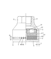
- the jet head body 2 and the baffle plate 5 located in the gap 6 are formed in a conical shape.
- the discharge form of the liquefied fire extinguishing agent is set to a predetermined angle with respect to the axial direction of the orifice 31 (in this embodiment, about 65 °, , Can be set to any angle from 0 to 90 °).
- the width dimension D of the gap 6 formed by the annular slit can be appropriately set depending on the capacity of the liquefied fire extinguishing agent jet head 1 and the target liquefied fire extinguishing agent, but is preferably 30 mm or less, and more preferably 30 mm or less. Is set to about 1 mm to 10 mm.
- the diffusion characteristics of the liquefied fire extinguishing agent in the same direction as the axial direction of the orifice 31 are improved, and further, the liquefied fire extinguishing agent is provided with a diffusion characteristic of a component perpendicular to the axial direction of the orifice 31, thereby achieving liquefaction extinguishing.
- the agent can be diffused and vaporized over a wider range.
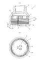
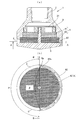
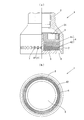
- the gap 6 is formed at the lower end side of the ejection head main body 2.
- the discharge form of the liquefied fire extinguishing agent can be made to be a disk shape in a direction orthogonal to the axial direction of the orifice 31.
- the width dimension D of the gap 6 formed by the annular slit can be appropriately set depending on the capacity of the liquefied fire extinguishing agent jet head 1 and the target liquefied fire extinguishing agent, but is preferably 30 mm or less, and more preferably 30 mm or less. Is set to about 1 mm to 10 mm.
- the dimension T in the thickness direction of the gap 6 formed by the annular slit is preferably 30 mm or less, more preferably 1 mm to 10 mm so that the discharge direction of the liquefied fire extinguishing agent can be regulated in a specific direction. Set to about.
- the diffusion characteristics of the liquefied fire extinguishing agent in the direction orthogonal to the axial direction of the orifice 31 can be improved, and the liquefied fire extinguishing agent can be diffused and vaporized over a wider range.
- the orifice plate 3 and the porous member 4 have a single-stage structure.
- a two-stage structure or a multi-stage structure of three or more stages
- the uniform diffusion characteristics of the liquefied fire extinguishing agent inside the ejection head main body 2 can be improved.
- the baffle plate 5 is screwed to the orifice plate 3 by a screw portion 51 penetrating through the center of the porous member 4.
- the baffle plate 5 may be fastened.
- bulging portions 23 and 54 that partially protrude to the outer peripheral side are formed on the ejection head main body 2 and the baffle plate 5, and the bulging portions 23 and 54 are formed.
- the ejection head main body 2 and the baffle plate 5 can be fastened using the screw member 8.
- a spacer 81 can be interposed at the position of the screw member 8 as necessary.
- the ejection head main body 2 and the baffle plate 5 can be fastened by using a screw member 8 penetrating the porous member 4.
- an operation hole for attaching a fastener (not shown) when connecting the ejection head body 2 to a pipe (not shown) for supplying a liquefied fire extinguishing agent is provided on the outer peripheral surface of the ejection head body 2. 24 are formed.
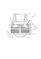
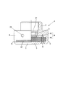
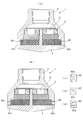
- the discharged form of the liquefied fire extinguishing agent has a fan shape having a predetermined angle ⁇ in a direction orthogonal to the axial direction of the orifice 31. You can also do so.
- the liquefied fire extinguishing agent is released by closing a part of the gap 6 formed between the ejection head main body 2 and the baffle plate 5 and formed of an annular slit for discharging the liquefied fire extinguishing agent by the closing member 62. Can be easily obtained.
- the angle ⁇ can be set to an arbitrary angle (for example, in the range of 30 ° to 330 °) according to the installation form of the ejection head 1 and the like. This improves the diffusion characteristics of the liquefied fire extinguishing agent in the direction perpendicular to the axial direction of the orifice 31, and allows the liquefied fire extinguishing agent to diffuse and vaporize in a specific direction. It can be suitably used for the ejection head 1 installed in the corner of the room to be used. In this case, as in the modified embodiment shown in FIG. 12-2, the orifices 31 formed at equal angular intervals (six at 60 ° intervals in the modified embodiment shown in FIG.
- the liquefied fire extinguishing agent is formed between the injection head main body 2 and the baffle plate 5 for making the discharge form fan-shaped.
- the partition wall surface (the end surface 62a of the closing member 62) forming both ends of the gap 6 is formed on an inclined surface facing the opposite side (back side) of the gap 6, and the inclined surface (the end surface 62a of the closing member 62) and the porous surface are formed.
- a wedge-shaped gap 6a can be formed between the outer peripheral surface of the member 4 and the member 4.
- the inclined surface (the end surface 62 a of the closing member 62) be formed in a shape that circumscribes the outer peripheral surface of the porous member 4.
- the flow of the liquefied fire extinguishing agent (vaporized state) is generated from the wedge-shaped gap 6a along the inclined surface (the end surface 62a of the closing member 62), and the radial direction of the liquefied fire extinguishing agent (vaporized state) is changed.
- the open area of the porous member 4 to the atmosphere can be increased (the standard of the open area of the porous member 4 to the atmosphere is larger than the angle ⁇ with respect to the angle ⁇ that limits the discharge angle of the liquefied fire extinguishing agent).
- the angle ⁇ can be used as a reference.
- the diffusion characteristics of the liquefied fire extinguishing agent in the direction orthogonal to the axial direction of the orifice can be further improved.
- the shape of the inclined surface (the end surface 62a of the closing member 62) is not limited to the planar shape of the modified example shown in FIGS. 13-1 and 13-2 (a).
- FIG. 13-2 (b) shows a case where a semi-circular opening is opened
- FIG. 13-2 (c) shows a case where a smaller semi-circular opening is opened. 13) processes the end face 62a of the closing member 62 so that the opening of a quarter circle is opened
- the circumcircle circle of the orifice 31 (in this embodiment, the common circumscribed circle of the six orifices 31) is formed outside the projected area. It is also possible to discharge the liquefied fire extinguishing agent through the through hole 7 formed.
- the through holes 7 are, as in the modification shown in FIG. 14, formed in a ring-shaped elongated hole formed in the rising portion 52 of the baffle plate 5 having a cap structure having a rising portion 52, or the deformation shown in FIG. 15.
- a plurality of annular stages (two stages in the illustrated example; two stages in the illustrated example) formed in the rising portion 52 of the baffle plate 5 having a cap structure having the rising portion 52 are preferable. It is possible to increase the area of the porous member 4 open to the atmosphere while maintaining a proper gap width.) As shown in a modified embodiment shown in FIG. (A portion where the outer peripheral surface of the arranged porous member 42 faces).
- the width dimension D and the formation interval of the through hole 7 can be appropriately set depending on the capacity of the liquefied fire extinguishing agent jet head 1 and the target liquefied fire extinguishing agent, but the width dimension D of the through hole 7 is preferable.
- the dimension T in the thickness direction of the through hole 7 is preferably 30 mm so that the discharge direction of the liquefied fire extinguishing agent can be regulated in a specific direction.
- it is set to about 1 mm to 10 mm.
- the direction of discharging the liquefied fire extinguishing agent is set to one direction.
- the direction of discharging the liquefied fire extinguishing agent can be set to two directions. it can.
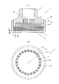
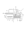
- the fourth embodiment of the liquefied fire extinguishing agent jet head of the present invention shown in FIG. 17 the first embodiment shown in FIG. 1 and the modified embodiment of the third embodiment shown in FIG.
- the liquefied fire extinguishing agent is formed into a cylindrical shape in the same direction as the axial direction of the orifice 31 (the axial direction of the central axis of the ejection head body 2) from the gap 6 formed between the ejection head body 2 and the baffle plate 5. From the through-holes 7 formed in an annular array formed in the lower part of the ejection head main body 2 (the part facing the outer peripheral surface of the porous member 42 disposed below). The orifice 31 is discharged in a disk shape in a direction perpendicular to the axial direction.
- the diffusion characteristics of the liquefied fire extinguishing agent in the same direction and the direction orthogonal to the axial direction of the orifice 31 can be improved, and the liquefied fire extinguishing agent can be diffused and vaporized in a wider range.
- the liquefied fire extinguishing agent ejection head of the present invention has been described based on a plurality of embodiments, but the present invention is not limited to the configuration described in the above embodiment, and the configuration described in each embodiment is not limited to the configuration described in each embodiment.
- the configuration can be appropriately changed within a range that does not deviate from the purpose, such as an appropriate combination.
- the liquefied fire extinguishing agent jet head of the present invention has excellent diffusion characteristics and vaporization characteristics of the liquefied fire extinguishing agent, can increase the range of fire extinguishing targets that can be covered by one jet head, and can increase the noise reduction rate. Therefore, it can be widely used for injection heads installed for discharging liquefied fire extinguisher to fire extinguishing equipment in fire extinguishing equipment using liquefied fire extinguishing agent, the application target is not limited to newly installed fire extinguishing equipment, injection head It can be applied to existing fire extinguishing equipment only by replacing
Landscapes
- Business, Economics & Management (AREA)
- Emergency Management (AREA)
- Health & Medical Sciences (AREA)
- Public Health (AREA)
- Nozzles (AREA)
- Fire-Extinguishing By Fire Departments, And Fire-Extinguishing Equipment And Control Thereof (AREA)
- Chemical & Material Sciences (AREA)
- Chemical Kinetics & Catalysis (AREA)
- General Chemical & Material Sciences (AREA)
- Fire-Extinguishing Compositions (AREA)
Priority Applications (11)
| Application Number | Priority Date | Filing Date | Title |
|---|---|---|---|
| JP2020550429A JP7299629B2 (ja) | 2018-10-02 | 2019-09-30 | 液化消火剤用噴射ヘッド |
| EP23158146.3A EP4205818B1 (en) | 2018-10-02 | 2019-09-30 | Injection head for liquid fire extinguishing agent |
| CN201980042481.3A CN112312975B (zh) | 2018-10-02 | 2019-09-30 | 液化灭火剂用喷射头 |
| CA3104466A CA3104466C (en) | 2018-10-02 | 2019-09-30 | Injection head for liquid fire extinguishing agent |
| EP19869477.0A EP3815752B1 (en) | 2018-10-02 | 2019-09-30 | Injection head for liquid fire extinguishing agent |
| US17/251,540 US11369978B2 (en) | 2018-10-02 | 2019-09-30 | Injection head for liquid fire extinguishing agent |
| SG11202012389XA SG11202012389XA (en) | 2018-10-02 | 2019-09-30 | Spray head for liquefied fire-extinguishing agent |
| KR1020207035922A KR102755691B1 (ko) | 2018-10-02 | 2019-09-30 | 액화 소화제용 분사 헤드 |
| ES19869477T ES2947441T3 (es) | 2018-10-02 | 2019-09-30 | Cabezal de inyección para agente líquido de extinción de incendios |
| MYPI2020006578A MY205571A (en) | 2018-10-02 | 2019-09-30 | Injection head for liquid fire extinguishing agent |
| PH12020552242A PH12020552242A1 (en) | 2018-10-02 | 2020-12-21 | Spray head for liquefied fire-extinguishing agent |
Applications Claiming Priority (2)
| Application Number | Priority Date | Filing Date | Title |
|---|---|---|---|
| JP2018187665 | 2018-10-02 | ||
| JP2018-187665 | 2018-10-02 |
Publications (1)
| Publication Number | Publication Date |
|---|---|
| WO2020071329A1 true WO2020071329A1 (ja) | 2020-04-09 |
Family
ID=70055552
Family Applications (1)
| Application Number | Title | Priority Date | Filing Date |
|---|---|---|---|
| PCT/JP2019/038588 Ceased WO2020071329A1 (ja) | 2018-10-02 | 2019-09-30 | 液化消火剤用噴射ヘッド |
Country Status (11)
| Country | Link |
|---|---|
| US (1) | US11369978B2 (enExample) |
| EP (2) | EP4205818B1 (enExample) |
| JP (1) | JP7299629B2 (enExample) |
| KR (1) | KR102755691B1 (enExample) |
| CN (1) | CN112312975B (enExample) |
| ES (2) | ES2947441T3 (enExample) |
| MY (1) | MY205571A (enExample) |
| PH (1) | PH12020552242A1 (enExample) |
| SG (1) | SG11202012389XA (enExample) |
| TW (1) | TWI799647B (enExample) |
| WO (1) | WO2020071329A1 (enExample) |
Cited By (2)
| Publication number | Priority date | Publication date | Assignee | Title |
|---|---|---|---|---|
| CN112206448A (zh) * | 2020-09-23 | 2021-01-12 | 诸佳枫 | 一种在喷水时可最大程度减少噪音的喷水枪头 |
| WO2024257508A1 (ja) * | 2023-06-13 | 2024-12-19 | 株式会社コーアツ | ガス系消火設備用の消音手段を備えた噴射ヘッド |
Families Citing this family (4)
| Publication number | Priority date | Publication date | Assignee | Title |
|---|---|---|---|---|
| US11060460B1 (en) * | 2019-04-01 | 2021-07-13 | Marine Turbine Technologies, LLC | Fuel distribution system for gas turbine engine |
| WO2021154287A1 (en) * | 2020-01-31 | 2021-08-05 | Carrier Corporation | Low noise discharge nozzle |
| US20230293921A1 (en) * | 2022-03-21 | 2023-09-21 | Carrier Corporation | Low noise nozzle assembly for fire suppression system |
| US20250303208A1 (en) * | 2024-03-29 | 2025-10-02 | The Reliable Automatic Sprinkler Co. Inc. | Foam-water fire sprinkler |
Citations (5)
| Publication number | Priority date | Publication date | Assignee | Title |
|---|---|---|---|---|
| JPS52163995U (enExample) * | 1976-06-07 | 1977-12-12 | ||
| EP1151800A2 (en) * | 2000-05-05 | 2001-11-07 | Vesta Srl | Silenced nozzle for discharge of extinguishing gas |
| JP2011125673A (ja) * | 2009-11-02 | 2011-06-30 | Koatsu Co Ltd | ガス系消火設備用の消音機能を有する噴射ヘッド |
| JP2011255152A (ja) * | 2009-10-23 | 2011-12-22 | Air Water Safety Service Inc | ガス消火設備 |
| JP5276730B1 (ja) * | 2012-03-21 | 2013-08-28 | 株式会社コーアツ | ガス系消火設備用の消音機能を有する噴射ヘッド |
Family Cites Families (15)
| Publication number | Priority date | Publication date | Assignee | Title |
|---|---|---|---|---|
| US3022014A (en) * | 1958-11-12 | 1962-02-20 | Stephen A Young | Shower head |
| US5404957A (en) * | 1993-10-18 | 1995-04-11 | Mccormack; Pat | Fire retardant foam generator |
| US6763894B2 (en) * | 2001-08-01 | 2004-07-20 | Kidde-Fenwal, Inc. | Clean agent fire suppression system and rapid atomizing nozzle in the same |
| US20050001065A1 (en) * | 2001-08-01 | 2005-01-06 | Kidde-Fenwal, Inc. | Nozzle apparatus and method for atomizing fluids |
| CN200951280Y (zh) * | 2006-09-06 | 2007-09-26 | 南京消防器材股份有限公司 | 低压二氧化碳灭火系统专用喷头 |
| WO2010071622A1 (en) * | 2008-12-18 | 2010-06-24 | Utc Fire & Security Corporation | Atomizing nozzle for a fire suppression system |
| EP2425877B1 (en) * | 2009-04-27 | 2017-09-06 | Hochiki Corporation | Fire prevention equipment |
| JP5452193B2 (ja) * | 2009-12-02 | 2014-03-26 | 株式会社Nttファシリティーズ | 整流筒及びこれを備えたガス消火システム |
| TWI566804B (zh) * | 2012-02-21 | 2017-01-21 | 高壓股份有限公司 | 氣體系滅火設備用的具有消音功能的噴射頭 |
| US9597537B2 (en) * | 2012-05-03 | 2017-03-21 | Koatsu Co., Ltd. | Injection head having silencing function for gas type fire extinguisher |
| JP6196955B2 (ja) * | 2013-10-02 | 2017-09-13 | エア・ウォーター防災株式会社 | 消火ガス噴射装置およびそれを備えたガス消火装置 |
| CN107847776A (zh) * | 2015-12-04 | 2018-03-27 | 泰科消防产品有限合伙公司 | 用于惰性气体排出系统的低压降声抑制器喷嘴 |
| WO2018123656A1 (ja) * | 2016-12-26 | 2018-07-05 | 株式会社コーアツ | ガス系消火設備用の消音機能を有する噴射ヘッド及びその保管・組立方法 |
| CN106861101A (zh) * | 2017-04-11 | 2017-06-20 | 广州广消阀门有限公司 | 一种氟化酮气体灭火装置 |
| US11130010B2 (en) * | 2017-05-19 | 2021-09-28 | Koatsu Co., Ltd. | Injection head for liquefied fire-extinguishing agent |
-
2019
- 2019-09-20 TW TW108133940A patent/TWI799647B/zh active
- 2019-09-30 EP EP23158146.3A patent/EP4205818B1/en active Active
- 2019-09-30 SG SG11202012389XA patent/SG11202012389XA/en unknown
- 2019-09-30 MY MYPI2020006578A patent/MY205571A/en unknown
- 2019-09-30 US US17/251,540 patent/US11369978B2/en active Active
- 2019-09-30 CN CN201980042481.3A patent/CN112312975B/zh active Active
- 2019-09-30 WO PCT/JP2019/038588 patent/WO2020071329A1/ja not_active Ceased
- 2019-09-30 EP EP19869477.0A patent/EP3815752B1/en active Active
- 2019-09-30 JP JP2020550429A patent/JP7299629B2/ja active Active
- 2019-09-30 ES ES19869477T patent/ES2947441T3/es active Active
- 2019-09-30 ES ES23158146T patent/ES2973997T3/es active Active
- 2019-09-30 KR KR1020207035922A patent/KR102755691B1/ko active Active
-
2020
- 2020-12-21 PH PH12020552242A patent/PH12020552242A1/en unknown
Patent Citations (5)
| Publication number | Priority date | Publication date | Assignee | Title |
|---|---|---|---|---|
| JPS52163995U (enExample) * | 1976-06-07 | 1977-12-12 | ||
| EP1151800A2 (en) * | 2000-05-05 | 2001-11-07 | Vesta Srl | Silenced nozzle for discharge of extinguishing gas |
| JP2011255152A (ja) * | 2009-10-23 | 2011-12-22 | Air Water Safety Service Inc | ガス消火設備 |
| JP2011125673A (ja) * | 2009-11-02 | 2011-06-30 | Koatsu Co Ltd | ガス系消火設備用の消音機能を有する噴射ヘッド |
| JP5276730B1 (ja) * | 2012-03-21 | 2013-08-28 | 株式会社コーアツ | ガス系消火設備用の消音機能を有する噴射ヘッド |
Non-Patent Citations (1)
| Title |
|---|
| See also references of EP3815752A4 * |
Cited By (3)
| Publication number | Priority date | Publication date | Assignee | Title |
|---|---|---|---|---|
| CN112206448A (zh) * | 2020-09-23 | 2021-01-12 | 诸佳枫 | 一种在喷水时可最大程度减少噪音的喷水枪头 |
| WO2024257508A1 (ja) * | 2023-06-13 | 2024-12-19 | 株式会社コーアツ | ガス系消火設備用の消音手段を備えた噴射ヘッド |
| JP7669013B1 (ja) * | 2023-06-13 | 2025-04-28 | 株式会社コーアツ | ガス系消火設備用の消音手段を備えた噴射ヘッド |
Also Published As
| Publication number | Publication date |
|---|---|
| EP3815752A1 (en) | 2021-05-05 |
| KR102755691B1 (ko) | 2025-01-20 |
| CA3104466A1 (en) | 2020-04-09 |
| US20210252530A1 (en) | 2021-08-19 |
| EP4205818B1 (en) | 2024-02-14 |
| PH12020552242A1 (en) | 2021-06-28 |
| JPWO2020071329A1 (ja) | 2021-09-16 |
| TWI799647B (zh) | 2023-04-21 |
| SG11202012389XA (en) | 2021-01-28 |
| JP7299629B2 (ja) | 2023-06-28 |
| ES2973997T3 (es) | 2024-06-25 |
| EP3815752C0 (en) | 2023-06-07 |
| CN112312975A (zh) | 2021-02-02 |
| EP3815752B1 (en) | 2023-06-07 |
| KR20210063278A (ko) | 2021-06-01 |
| EP4205818A1 (en) | 2023-07-05 |
| TW202026040A (zh) | 2020-07-16 |
| MY205571A (en) | 2024-10-26 |
| EP3815752A4 (en) | 2022-02-09 |
| US11369978B2 (en) | 2022-06-28 |
| EP4205818C0 (en) | 2024-02-14 |
| CN112312975B (zh) | 2022-10-18 |
| ES2947441T3 (es) | 2023-08-09 |
Similar Documents
| Publication | Publication Date | Title |
|---|---|---|
| JP7299629B2 (ja) | 液化消火剤用噴射ヘッド | |
| ES2972592T3 (es) | Cabezal de inyección con función silenciadora para extintor de incendios de gas y método de almacenamiento y ensamblaje del mismo | |
| JP7031829B2 (ja) | 液化消火剤用噴射ヘッド | |
| JPWO2020071329A5 (enExample) | ||
| CA3029714C (en) | End cap agent nozzle | |
| CA3104466C (en) | Injection head for liquid fire extinguishing agent | |
| RU2786611C2 (ru) | Распылительная головка для жидкого огнетушащего вещества | |
| JP7669013B1 (ja) | ガス系消火設備用の消音手段を備えた噴射ヘッド | |
| HK40014712A (en) | Spray head for liquefied fire-extinguishing agent | |
| CA3048359C (en) | Injection head having silencing function for gas-type fire extinguisher and method for storing and assembling thereof |
Legal Events
| Date | Code | Title | Description |
|---|---|---|---|
| 121 | Ep: the epo has been informed by wipo that ep was designated in this application |
Ref document number: 19869477 Country of ref document: EP Kind code of ref document: A1 |
|
| ENP | Entry into the national phase |
Ref document number: 2020550429 Country of ref document: JP Kind code of ref document: A |
|
| ENP | Entry into the national phase |
Ref document number: 2019869477 Country of ref document: EP Effective date: 20201202 Ref document number: 3104466 Country of ref document: CA |
|
| WWE | Wipo information: entry into national phase |
Ref document number: 2101001707 Country of ref document: TH |
|
| NENP | Non-entry into the national phase |
Ref country code: DE |
|
| WWE | Wipo information: entry into national phase |
Ref document number: 2021112366 Country of ref document: RU |