WO2020071329A1 - Spray head for liquefied fire-extinguishing agent - Google Patents
Spray head for liquefied fire-extinguishing agentInfo
- Publication number
- WO2020071329A1 WO2020071329A1 PCT/JP2019/038588 JP2019038588W WO2020071329A1 WO 2020071329 A1 WO2020071329 A1 WO 2020071329A1 JP 2019038588 W JP2019038588 W JP 2019038588W WO 2020071329 A1 WO2020071329 A1 WO 2020071329A1
- Authority
- WO
- WIPO (PCT)
- Prior art keywords
- fire extinguishing
- extinguishing agent
- liquefied fire
- liquefied
- orifice
- Prior art date
Links
Images


Classifications
-
- A—HUMAN NECESSITIES
- A62—LIFE-SAVING; FIRE-FIGHTING
- A62C—FIRE-FIGHTING
- A62C31/00—Delivery of fire-extinguishing material
- A62C31/02—Nozzles specially adapted for fire-extinguishing
- A62C31/05—Nozzles specially adapted for fire-extinguishing with two or more outlets
-
- B—PERFORMING OPERATIONS; TRANSPORTING
- B05—SPRAYING OR ATOMISING IN GENERAL; APPLYING FLUENT MATERIALS TO SURFACES, IN GENERAL
- B05B—SPRAYING APPARATUS; ATOMISING APPARATUS; NOZZLES
- B05B1/00—Nozzles, spray heads or other outlets, with or without auxiliary devices such as valves, heating means
- B05B1/34—Nozzles, spray heads or other outlets, with or without auxiliary devices such as valves, heating means designed to influence the nature of flow of the liquid or other fluent material, e.g. to produce swirl
-
- A—HUMAN NECESSITIES
- A62—LIFE-SAVING; FIRE-FIGHTING
- A62C—FIRE-FIGHTING
- A62C31/00—Delivery of fire-extinguishing material
- A62C31/02—Nozzles specially adapted for fire-extinguishing
-
- A—HUMAN NECESSITIES
- A62—LIFE-SAVING; FIRE-FIGHTING
- A62C—FIRE-FIGHTING
- A62C35/00—Permanently-installed equipment
- A62C35/58—Pipe-line systems
- A62C35/68—Details, e.g. of pipes or valve systems
-
- B—PERFORMING OPERATIONS; TRANSPORTING
- B05—SPRAYING OR ATOMISING IN GENERAL; APPLYING FLUENT MATERIALS TO SURFACES, IN GENERAL
- B05B—SPRAYING APPARATUS; ATOMISING APPARATUS; NOZZLES
- B05B1/00—Nozzles, spray heads or other outlets, with or without auxiliary devices such as valves, heating means
- B05B1/002—Nozzles, spray heads or other outlets, with or without auxiliary devices such as valves, heating means designed to reduce the generation or the transmission of noise or to produce a particular sound; associated with noise monitoring means
-
- B—PERFORMING OPERATIONS; TRANSPORTING
- B05—SPRAYING OR ATOMISING IN GENERAL; APPLYING FLUENT MATERIALS TO SURFACES, IN GENERAL
- B05B—SPRAYING APPARATUS; ATOMISING APPARATUS; NOZZLES
- B05B1/00—Nozzles, spray heads or other outlets, with or without auxiliary devices such as valves, heating means
- B05B1/02—Nozzles, spray heads or other outlets, with or without auxiliary devices such as valves, heating means designed to produce a jet, spray, or other discharge of particular shape or nature, e.g. in single drops, or having an outlet of particular shape
- B05B1/04—Nozzles, spray heads or other outlets, with or without auxiliary devices such as valves, heating means designed to produce a jet, spray, or other discharge of particular shape or nature, e.g. in single drops, or having an outlet of particular shape in flat form, e.g. fan-like, sheet-like
- B05B1/044—Slits, i.e. narrow openings defined by two straight and parallel lips; Elongated outlets for producing very wide discharges, e.g. fluid curtains
-
- B—PERFORMING OPERATIONS; TRANSPORTING
- B05—SPRAYING OR ATOMISING IN GENERAL; APPLYING FLUENT MATERIALS TO SURFACES, IN GENERAL
- B05B—SPRAYING APPARATUS; ATOMISING APPARATUS; NOZZLES
- B05B1/00—Nozzles, spray heads or other outlets, with or without auxiliary devices such as valves, heating means
- B05B1/02—Nozzles, spray heads or other outlets, with or without auxiliary devices such as valves, heating means designed to produce a jet, spray, or other discharge of particular shape or nature, e.g. in single drops, or having an outlet of particular shape
- B05B1/04—Nozzles, spray heads or other outlets, with or without auxiliary devices such as valves, heating means designed to produce a jet, spray, or other discharge of particular shape or nature, e.g. in single drops, or having an outlet of particular shape in flat form, e.g. fan-like, sheet-like
- B05B1/046—Outlets formed, e.g. cut, in the circumference of tubular or spherical elements
-
- B—PERFORMING OPERATIONS; TRANSPORTING
- B05—SPRAYING OR ATOMISING IN GENERAL; APPLYING FLUENT MATERIALS TO SURFACES, IN GENERAL
- B05B—SPRAYING APPARATUS; ATOMISING APPARATUS; NOZZLES
- B05B1/00—Nozzles, spray heads or other outlets, with or without auxiliary devices such as valves, heating means
- B05B1/14—Nozzles, spray heads or other outlets, with or without auxiliary devices such as valves, heating means with multiple outlet openings; with strainers in or outside the outlet opening
-
- B—PERFORMING OPERATIONS; TRANSPORTING
- B05—SPRAYING OR ATOMISING IN GENERAL; APPLYING FLUENT MATERIALS TO SURFACES, IN GENERAL
- B05B—SPRAYING APPARATUS; ATOMISING APPARATUS; NOZZLES
- B05B15/00—Details of spraying plant or spraying apparatus not otherwise provided for; Accessories
- B05B15/40—Filters located upstream of the spraying outlets
-
- A—HUMAN NECESSITIES
- A62—LIFE-SAVING; FIRE-FIGHTING
- A62C—FIRE-FIGHTING
- A62C99/00—Subject matter not provided for in other groups of this subclass
- A62C99/0009—Methods of extinguishing or preventing the spread of fire by cooling down or suffocating the flames
- A62C99/0018—Methods of extinguishing or preventing the spread of fire by cooling down or suffocating the flames using gases or vapours that do not support combustion, e.g. steam, carbon dioxide
-
- A—HUMAN NECESSITIES
- A62—LIFE-SAVING; FIRE-FIGHTING
- A62D—CHEMICAL MEANS FOR EXTINGUISHING FIRES OR FOR COMBATING OR PROTECTING AGAINST HARMFUL CHEMICAL AGENTS; CHEMICAL MATERIALS FOR USE IN BREATHING APPARATUS
- A62D1/00—Fire-extinguishing compositions; Use of chemical substances in extinguishing fires
- A62D1/0028—Liquid extinguishing substances
- A62D1/0057—Polyhaloalkanes
-
- B—PERFORMING OPERATIONS; TRANSPORTING
- B05—SPRAYING OR ATOMISING IN GENERAL; APPLYING FLUENT MATERIALS TO SURFACES, IN GENERAL
- B05B—SPRAYING APPARATUS; ATOMISING APPARATUS; NOZZLES
- B05B1/00—Nozzles, spray heads or other outlets, with or without auxiliary devices such as valves, heating means
- B05B1/26—Nozzles, spray heads or other outlets, with or without auxiliary devices such as valves, heating means with means for mechanically breaking-up or deflecting the jet after discharge, e.g. with fixed deflectors; Breaking-up the discharged liquid or other fluent material by impinging jets
- B05B1/262—Nozzles, spray heads or other outlets, with or without auxiliary devices such as valves, heating means with means for mechanically breaking-up or deflecting the jet after discharge, e.g. with fixed deflectors; Breaking-up the discharged liquid or other fluent material by impinging jets with fixed deflectors
- B05B1/265—Nozzles, spray heads or other outlets, with or without auxiliary devices such as valves, heating means with means for mechanically breaking-up or deflecting the jet after discharge, e.g. with fixed deflectors; Breaking-up the discharged liquid or other fluent material by impinging jets with fixed deflectors the liquid or other fluent material being symmetrically deflected about the axis of the nozzle
Definitions
- the present invention relates to an injection head for a liquefied fire extinguishing agent having a high boiling point such as a halide.
- a liquefied fire extinguishing agent having a high boiling point such as a halide, for example, dodecafluoro-2-methylpentan-3-one (CF 3 CF 2 C (O) CF (CF 3 ) 2 , boiling point 49) is used as a fire extinguishing agent.
- a halide for example, dodecafluoro-2-methylpentan-3-one
- FK-5-1-12 When using 2 ° C., NFPA / ISO registered name “FK-5-1-12”), use a spray head that sprays the liquefied fire extinguisher in a mist to discharge the liquefied fire extinguisher to the fire extinguishing target compartment. Like that.
- the spray head that sprays the liquefied fire extinguishing agent in the form of a mist has a problem that the diffusion characteristics and the vaporization characteristics of the liquefied fire extinguishing agent are poor, particularly the diffusion characteristics in the radiation axis direction, and the fire extinguishing target range that can be covered by one spray head is small.
- An object of the present invention is to provide a liquefied fire extinguisher jet head that can increase the range of fire extinguishing targets that can be covered by one jet head and can increase the noise reduction rate.
- a liquefied fire extinguishing agent jet head of the present invention is a jet head installed for discharging a liquefied fire extinguishing agent to a fire extinguishing target section in a fire extinguishing facility using a liquefied fire extinguishing agent,
- An injection head body to which a pipe for supplying the agent is connected an orifice plate formed on the injection head body, and having an orifice through which the liquefied fire extinguishing agent passes, and a block-shaped orifice disposed at the outlet of the orifice.
- the liquefied fire extinguishing agent can be discharged in a cylindrical shape in the same direction as the orifice.
- the liquefied fire extinguishing agent may be discharged in a conical shape having a predetermined angle with respect to the axial direction of the orifice.
- the discharge form of the liquefied fire extinguishing agent may be a disk shape in a direction perpendicular to the axial direction of the orifice.
- the liquefied fire extinguishing agent may be discharged in a fan shape having a predetermined angle in a direction perpendicular to the axial direction of the orifice.
- partition walls forming both ends of the gap formed between the injection head body and the baffle plate for making the discharge form of the liquefied fire extinguisher fan-shaped are formed on an inclined surface facing the opposite side of the gap.
- a wedge-shaped gap may be formed between the inclined surface and the porous member.
- the width dimension of the gap and / or the through hole is preferably 30 mm or less, more preferably 1 mm to 10 mm, or the ratio of the inner diameter to the outer diameter of the gap and / or The ratio of the diameter of the small diameter circle and the diameter of the large diameter circle that are in common contact can be set to 0.70 or more.
- the liquefied fire extinguishing agent supplied through the orifice diffuses while flowing through the block-shaped porous member without being short-passed, and is liquefied by the baffle plate.
- the diffusion characteristics and vaporization characteristics of the liquefied fire extinguishing agent can be improved, and the liquefied fire extinguishing agent can be diffused and vaporized over a wide range.
- the fire extinguishing target range that can be covered by one ejection head can be increased.
- the liquefied fire extinguishing agent flows and diffuses in the block-shaped porous member without being short-passed and is discharged, the noise generated when the liquefied fire extinguishing agent is discharged can be reduced.
- the diffusion characteristics of the liquefied fire extinguishing agent in the same direction as the axial direction of the orifice are improved, and Can be diffused and vaporized over a wider range.
- the diffusion characteristics of the liquefied fire extinguishing agent in the same direction as the axial direction of the orifice are improved.
- the liquefied fire extinguishing agent can be diffused and vaporized over a wider range by providing a diffusion characteristic of a component orthogonal to the axial direction of the orifice of the liquefied fire extinguishing agent.
- the diffusion characteristics of the liquefied fire extinguishing agent in the direction orthogonal to the axial direction of the orifice are improved, and The fire extinguisher can be diffused and vaporized over a wider range.
- the discharge form of the liquefied fire extinguishing agent fan-shaped having a predetermined angle in the direction orthogonal to the axial direction of the orifice, the diffusion characteristics of the liquefied fire extinguishing agent in the direction orthogonal to the axial direction of the orifice are improved.
- the liquefied fire extinguishing agent can be diffused and vaporized in a specific direction.
- partition walls forming both ends of the gap formed between the injection head body and the baffle plate for making the discharge form of the liquefied fire extinguisher fan-shaped are formed on an inclined surface facing the opposite side of the gap.
- the width dimension of the gap and / or the through hole is preferably 30 mm or less, more preferably 1 mm to 10 mm, or the ratio of the inner diameter to the outer diameter of the gap and / or The ratio of the diameter of the small diameter circle and the diameter of the large diameter circle that are in common contact can be set to 0.70 or more.
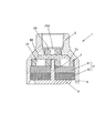
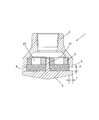
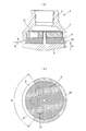
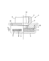
- FIG. 1 shows a first embodiment of a liquefied fire extinguishing agent jet head according to the present invention, wherein (a) is a front sectional view and (b) is a bottom view.
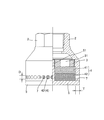
- FIG. 3 is a front sectional view showing a modified example of the first embodiment of the liquefied fire extinguishing agent jet head of the present invention.
- the modified example of the first embodiment of the liquefied fire extinguishing agent jet head of the present invention is shown, wherein (a) is a front sectional view and (b) is a bottom view.
- FIG. 3 is a front sectional view showing a modified example of the first embodiment of the liquefied fire extinguishing agent jet head of the present invention.
- 3 shows a modified example of the first embodiment of the liquefied fire extinguishing agent jet head of the present invention, wherein (a) is a front sectional view and (b) is a bottom sectional view.
- 3 shows a modified example of the first embodiment of the liquefied fire extinguishing agent jet head of the present invention, wherein (a) is a front sectional view and (b) is a bottom sectional view. It is sectional drawing which shows 2nd Example of the injection head for liquefied fire extinguishing agents of this invention. It is sectional drawing which shows 3rd Example of the injection head for liquefied fire extinguishing agents of this invention.
- FIGS. 7A and 7B show a modified example of the third embodiment of the liquefied fire extinguishing agent jet head of the present invention, wherein FIG. 7A is a front sectional view, and FIG.
- FIGS. 7A and 7B show a modified example of the third embodiment of the liquefied fire extinguishing agent jet head of the present invention, wherein FIG. 7A is a front sectional view, and FIG. 7B is a sectional view taken along line AA of FIG.
- FIGS. 7A and 7B show a modified example of the third embodiment of the liquefied fire extinguishing agent jet head of the present invention, wherein FIG. 7A is a front sectional view, and FIG. 7B is a sectional view taken along line AA of FIG. FIGS.
- FIG. 13A and 13B show a modified example of the third embodiment of the liquefied fire extinguishing agent jet head according to the present invention, in which FIG. 13A is a sectional view taken along line BB of FIG. Sectional views corresponding to (a) of the modified embodiment, and (c) to (e) are explanatory views of closing members having different shapes. It is a front view (partial sectional view) showing the modification of the 3rd example of the jet head for liquefied fire extinguishing agents of the present invention. It is a front view (partial sectional view) showing the modification of the 3rd example of the jet head for liquefied fire extinguishing agents of the present invention.
- FIG. 4A is a front sectional view
- FIG. 4B is a front sectional view
- FIG. 1 shows a first embodiment of a liquefied fire extinguishing agent ejection head according to the present invention.
- the liquefied fire extinguishing agent injection head 1 is an injection head 1 that is installed in a fire extinguishing facility that uses liquefied fire extinguishing agent to discharge the liquefied fire extinguishing agent to a fire extinguishing target section. (Omitted), an orifice plate 3 provided with an orifice 31 through which the liquefied fire extinguisher passes, and a block shape provided at an outlet of the orifice 31. And a baffle plate 5 disposed in contact with an end face of the porous member 4 on the side opposite to the outlet of the orifice 31.
- the baffle plate 5 includes at least the porous member 4.
- the liquefied fire extinguishing agent passes through the gap 6 formed between the ejection head main body 2 and the baffle plate 5 while covering the projected area of the circumscribed circle 31c of the orifice 31 on the end face. So that release.
- the ejection head 1 is formed in a circular shape whose center axis is rotationally symmetric (the same applies to the following embodiments). Further, a female screw (or a male screw) for connecting the pipe is formed in the ejection head main body 2 to which the pipe for supplying the liquefied fire extinguishing agent is connected.
- the liquefied fire extinguishing agent targeted by the liquefied fire extinguishing agent jet head 1 includes the following fire extinguishing agents (1) to (3).
- dodecafluoro-2-methylpentan-3-one CF 3 CF 2 C (O) CF (CF 3 ) 2 , boiling point 49.2 ° C., NFPA / ISO Registered name "FK-5-1-12").
- the orifice plate 3 has a disk shape in which one or a plurality (six in the present embodiment) of orifices 31 are formed at equal angular intervals at the center.
- the step 21 is detachably disposed, for example, via a screw formed on the step 21 and the peripheral surface of the orifice plate 3.
- the orifice plate 3 having the plurality of types of orifices 31 formed therein can be selected according to conditions such as an installation location.
- the block-shaped porous member 4 may be formed of an integral structure, or may be formed of a divided structure in which a plurality of porous members 41 and 42 are stacked as shown in this embodiment.
- the block-shaped porous member 4 is preferably made of an inorganic material (metal, metal oxide, metal hydroxide, or the like) having high shape retention performance, that is, not causing deformation or the like due to the discharge pressure of the liquefied fire extinguisher.
- the porous metal material (“Celmet” (registered trademark) manufactured by Sumitomo Electric Industries, Ltd.) composed of a three-dimensional network can be more preferably used.
- the pore diameter of the voids of the porous member 4 is made of a homogeneous material, and the material is varied along the flow direction of the liquefied fire extinguishing agent. More specifically, the pore diameter of the voids is changed in the flow direction of the liquefied fire extinguishing agent. For example, in the present embodiment, the pore diameter of the pores of the porous member 41 on the upstream side in the flow direction of the liquefied fire extinguishing agent is smaller than that of the porous member 42 on the downstream side. It can be made of a material that reduces the pore size of the void.
- the liquefied fire extinguishing agent flowing in the block-shaped porous member can be uniformly diffused. Can be.
- one end face of the porous member 4 has the ejection head main body 2 (including the orifice plate 3 in the present embodiment. The same applies to the embodiment.), So that it is disposed at the outlet of the orifice 31.
- the baffle plate 5 is configured to abut on the other end surface of the porous member 4, that is, the end surface of the porous member 4 opposite to the outlet of the orifice 31.
- the orifice plate 3 and the porous member 4 have a single-stage structure.
- a two-stage structure or a multi-stage structure of three or more stages
- the orifice plate 3A is configured to be detachable from the ejection head main body 2 through an opening on the connection portion side of the ejection head main body 2 with the pipe (see later-described drawing). 6, 9, 11, 14, and 15).
- the porous member 4 is stored in stock in a state where the porous member 4 is assembled to the ejection head main body 2, and the orifice plate 3A (orifice plate 3) corresponding to the flow rate of the liquefied fire extinguishing agent discharged from the ejection head at the time of shipment.
- the baffle plate 5 is provided with a screw part 51 penetrating through the center of the porous member 4 (the screw part 51 is formed integrally with the baffle plate 5 and, as in the modified embodiment shown in FIG. In the case where the screw portion 51 is formed of the screw member 8, one or a plurality of screw members 8 can be used.)
- the screw portion 51 is formed of a bolt and a nut and fastened to the orifice plate 3) so as to be fixed to the ejection head main body 2.
- the baffle plate 5 is in contact with the other end face of the porous member 4 so that at least the circumscribed circle 31c of the orifice 31 on the end face of the porous member 4 (in this embodiment, the common circle 31c of the six orifices 31).
- the projection area of the circumscribed circle 31c) is covered so that the liquefied fire extinguishing agent is not released from the projected area, and the liquefied fire extinguishing agent is discharged through the gap 6 formed between the ejection head main body 2 and the baffle plate 5. I am trying to do it.
- the gap 6 formed between the ejection head main body 2 and the baffle plate 5 is constituted by an annular slit whose outlet side is slightly widened, whereby the discharge form of the liquefied fire extinguishing agent is reduced.
- the orifice 31 has a cylindrical shape in the same direction as the axial direction (the axial direction of the central axis of the ejection head body 2).
- the width dimension D of the gap 6 formed by the annular slit can be appropriately set depending on the capacity of the liquefied fire extinguishing agent jet head 1 and the target liquefied fire extinguishing agent, but is preferably 30 mm or less, and more preferably 30 mm or less.
- the dimension T in the thickness direction of the gap 6 (baffle plate 5) formed by the annular slit is preferably 30 mm or less, and more preferably 30 mm or less so that the discharge direction of the liquefied fire extinguishing agent can be regulated in a specific direction.
- the liquefied fire extinguishing agent jet head 1 the liquefied fire extinguishing agent supplied via the orifice 31 diffuses while flowing through the block-shaped porous member 4 without making a short path, and the baffle plate 5
- the diffusion characteristics and vaporization characteristics of the liquefied fire extinguishing agent can be improved, and the liquefied fire extinguishing agent can be diffused and vaporized over a wide range.
- the fire extinguishing target range that can be covered by one ejection head 1 can be increased.
- the liquefied fire extinguishing agent flows and diffuses and is discharged in the block-shaped porous member 4 without causing a short path, noise generated when the liquefied fire extinguishing agent is discharged can be reduced.
- the gap 6 formed between the ejection head main body 2 and the baffle plate 5 is constituted by an annular slit whose outlet side is slightly widened.
- the axial direction of the orifice 31 of the liquefied fire extinguishing agent (the axial direction of the center axis of the injection head body 2) is not limited to this, and is constituted by a straight annular slit whose outlet side does not expand.
- the liquefied fire extinguishing agent can be diffused and vaporized over a wider range by improving the diffusion characteristics in the same direction.
- the ejection head main body 2 side is formed in a straight shape, and the baffle plate 5 side is formed as an annular slit which is wider than that of the first embodiment.
- the diffusion characteristics of the discharged liquefied fire extinguishing agent toward the center can be improved.
- the baffle plate 5 is fixed to the ejection head main body 2 by screwing the baffle plate 5 to the orifice plate 3 with the screw portion 51 penetrating the center of the porous member 4.
- the baffle plate 5 may have a cap structure having a rising portion 52 and may be screwed and fixed to the ejection head main body 2.
- the baffle plate 5 abuts on the other end face of the porous member 4, so that at least the circumscribed circle 31 c of the orifice 31 on the end face of the porous member 4 is formed.
- the projected area of the common circumscribed circle 31c) of the six orifices 31 is covered so that the liquefied fire extinguishing agent is not discharged from the projected area, and the circumscribed circle 31c of the orifice 31 of the baffle plate 5 ( In the present embodiment, the liquefied fire extinguishing agent is discharged through the through-hole 7 formed outside the projected area of the common circumscribed circle 31c) of the six orifices 31.
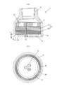
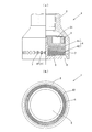
- the through-hole 7 is constituted by a long hole (a modified embodiment shown in FIG. 5) or a circular hole (a modified embodiment shown in FIG. 6) arranged in an annular shape. 31 is formed in a columnar shape in the same direction as the axial direction (axial direction of the central axis of the ejection head main body 2).
- the width dimension D and the formation interval of the through hole 7 can be appropriately set depending on the capacity of the liquefied fire extinguishing agent jet head 1 and the target liquefied fire extinguishing agent, but the width dimension D of the through hole 7 is preferable.
- the dimension T in the thickness direction of the through-hole 7 (baffle plate 5) is preferably 30 mm or less, more preferably 1 mm to 10 mm, so that the discharge direction of the liquefied fire extinguishing agent can be regulated in a specific direction. Set to about. Thereby, the diffusion characteristics of the liquefied fire extinguishing agent in the same direction as the axial direction of the orifice 31 (axial direction of the central axis of the ejection head main body 2) can be improved.
- the liquefied fire extinguishing agent is discharged in a cylindrical shape in the same direction as the axial direction of the orifice 31 (axial direction of the central axis of the ejection head main body 2).
- the discharge mode is not limited to this.
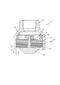
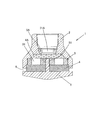
- the jet head body 2 and the baffle plate 5 located in the gap 6 are formed in a conical shape.
- the discharge form of the liquefied fire extinguishing agent is set to a predetermined angle with respect to the axial direction of the orifice 31 (in this embodiment, about 65 °, , Can be set to any angle from 0 to 90 °).
- the width dimension D of the gap 6 formed by the annular slit can be appropriately set depending on the capacity of the liquefied fire extinguishing agent jet head 1 and the target liquefied fire extinguishing agent, but is preferably 30 mm or less, and more preferably 30 mm or less. Is set to about 1 mm to 10 mm.
- the diffusion characteristics of the liquefied fire extinguishing agent in the same direction as the axial direction of the orifice 31 are improved, and further, the liquefied fire extinguishing agent is provided with a diffusion characteristic of a component perpendicular to the axial direction of the orifice 31, thereby achieving liquefaction extinguishing.
- the agent can be diffused and vaporized over a wider range.
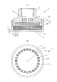
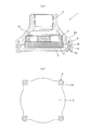
- the gap 6 is formed at the lower end side of the ejection head main body 2.
- the discharge form of the liquefied fire extinguishing agent can be made to be a disk shape in a direction orthogonal to the axial direction of the orifice 31.
- the width dimension D of the gap 6 formed by the annular slit can be appropriately set depending on the capacity of the liquefied fire extinguishing agent jet head 1 and the target liquefied fire extinguishing agent, but is preferably 30 mm or less, and more preferably 30 mm or less. Is set to about 1 mm to 10 mm.
- the dimension T in the thickness direction of the gap 6 formed by the annular slit is preferably 30 mm or less, more preferably 1 mm to 10 mm so that the discharge direction of the liquefied fire extinguishing agent can be regulated in a specific direction. Set to about.
- the diffusion characteristics of the liquefied fire extinguishing agent in the direction orthogonal to the axial direction of the orifice 31 can be improved, and the liquefied fire extinguishing agent can be diffused and vaporized over a wider range.
- the orifice plate 3 and the porous member 4 have a single-stage structure.
- a two-stage structure or a multi-stage structure of three or more stages
- the uniform diffusion characteristics of the liquefied fire extinguishing agent inside the ejection head main body 2 can be improved.
- the baffle plate 5 is screwed to the orifice plate 3 by a screw portion 51 penetrating through the center of the porous member 4.
- the baffle plate 5 may be fastened.
- bulging portions 23 and 54 that partially protrude to the outer peripheral side are formed on the ejection head main body 2 and the baffle plate 5, and the bulging portions 23 and 54 are formed.
- the ejection head main body 2 and the baffle plate 5 can be fastened using the screw member 8.
- a spacer 81 can be interposed at the position of the screw member 8 as necessary.
- the ejection head main body 2 and the baffle plate 5 can be fastened by using a screw member 8 penetrating the porous member 4.
- an operation hole for attaching a fastener (not shown) when connecting the ejection head body 2 to a pipe (not shown) for supplying a liquefied fire extinguishing agent is provided on the outer peripheral surface of the ejection head body 2. 24 are formed.
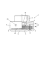
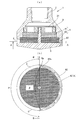
- the discharged form of the liquefied fire extinguishing agent has a fan shape having a predetermined angle ⁇ in a direction orthogonal to the axial direction of the orifice 31. You can also do so.
- the liquefied fire extinguishing agent is released by closing a part of the gap 6 formed between the ejection head main body 2 and the baffle plate 5 and formed of an annular slit for discharging the liquefied fire extinguishing agent by the closing member 62. Can be easily obtained.
- the angle ⁇ can be set to an arbitrary angle (for example, in the range of 30 ° to 330 °) according to the installation form of the ejection head 1 and the like. This improves the diffusion characteristics of the liquefied fire extinguishing agent in the direction perpendicular to the axial direction of the orifice 31, and allows the liquefied fire extinguishing agent to diffuse and vaporize in a specific direction. It can be suitably used for the ejection head 1 installed in the corner of the room to be used. In this case, as in the modified embodiment shown in FIG. 12-2, the orifices 31 formed at equal angular intervals (six at 60 ° intervals in the modified embodiment shown in FIG.
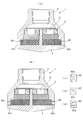
- the liquefied fire extinguishing agent is formed between the injection head main body 2 and the baffle plate 5 for making the discharge form fan-shaped.
- the partition wall surface (the end surface 62a of the closing member 62) forming both ends of the gap 6 is formed on an inclined surface facing the opposite side (back side) of the gap 6, and the inclined surface (the end surface 62a of the closing member 62) and the porous surface are formed.
- a wedge-shaped gap 6a can be formed between the outer peripheral surface of the member 4 and the member 4.
- the inclined surface (the end surface 62 a of the closing member 62) be formed in a shape that circumscribes the outer peripheral surface of the porous member 4.
- the flow of the liquefied fire extinguishing agent (vaporized state) is generated from the wedge-shaped gap 6a along the inclined surface (the end surface 62a of the closing member 62), and the radial direction of the liquefied fire extinguishing agent (vaporized state) is changed.
- the open area of the porous member 4 to the atmosphere can be increased (the standard of the open area of the porous member 4 to the atmosphere is larger than the angle ⁇ with respect to the angle ⁇ that limits the discharge angle of the liquefied fire extinguishing agent).
- the angle ⁇ can be used as a reference.
- the diffusion characteristics of the liquefied fire extinguishing agent in the direction orthogonal to the axial direction of the orifice can be further improved.
- the shape of the inclined surface (the end surface 62a of the closing member 62) is not limited to the planar shape of the modified example shown in FIGS. 13-1 and 13-2 (a).
- FIG. 13-2 (b) shows a case where a semi-circular opening is opened
- FIG. 13-2 (c) shows a case where a smaller semi-circular opening is opened. 13) processes the end face 62a of the closing member 62 so that the opening of a quarter circle is opened
- the circumcircle circle of the orifice 31 (in this embodiment, the common circumscribed circle of the six orifices 31) is formed outside the projected area. It is also possible to discharge the liquefied fire extinguishing agent through the through hole 7 formed.
- the through holes 7 are, as in the modification shown in FIG. 14, formed in a ring-shaped elongated hole formed in the rising portion 52 of the baffle plate 5 having a cap structure having a rising portion 52, or the deformation shown in FIG. 15.
- a plurality of annular stages (two stages in the illustrated example; two stages in the illustrated example) formed in the rising portion 52 of the baffle plate 5 having a cap structure having the rising portion 52 are preferable. It is possible to increase the area of the porous member 4 open to the atmosphere while maintaining a proper gap width.) As shown in a modified embodiment shown in FIG. (A portion where the outer peripheral surface of the arranged porous member 42 faces).
- the width dimension D and the formation interval of the through hole 7 can be appropriately set depending on the capacity of the liquefied fire extinguishing agent jet head 1 and the target liquefied fire extinguishing agent, but the width dimension D of the through hole 7 is preferable.
- the dimension T in the thickness direction of the through hole 7 is preferably 30 mm so that the discharge direction of the liquefied fire extinguishing agent can be regulated in a specific direction.
- it is set to about 1 mm to 10 mm.
- the direction of discharging the liquefied fire extinguishing agent is set to one direction.
- the direction of discharging the liquefied fire extinguishing agent can be set to two directions. it can.
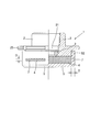
- the fourth embodiment of the liquefied fire extinguishing agent jet head of the present invention shown in FIG. 17 the first embodiment shown in FIG. 1 and the modified embodiment of the third embodiment shown in FIG.
- the liquefied fire extinguishing agent is formed into a cylindrical shape in the same direction as the axial direction of the orifice 31 (the axial direction of the central axis of the ejection head body 2) from the gap 6 formed between the ejection head body 2 and the baffle plate 5. From the through-holes 7 formed in an annular array formed in the lower part of the ejection head main body 2 (the part facing the outer peripheral surface of the porous member 42 disposed below). The orifice 31 is discharged in a disk shape in a direction perpendicular to the axial direction.
- the diffusion characteristics of the liquefied fire extinguishing agent in the same direction and the direction orthogonal to the axial direction of the orifice 31 can be improved, and the liquefied fire extinguishing agent can be diffused and vaporized in a wider range.
- the liquefied fire extinguishing agent ejection head of the present invention has been described based on a plurality of embodiments, but the present invention is not limited to the configuration described in the above embodiment, and the configuration described in each embodiment is not limited to the configuration described in each embodiment.
- the configuration can be appropriately changed within a range that does not deviate from the purpose, such as an appropriate combination.
- the liquefied fire extinguishing agent jet head of the present invention has excellent diffusion characteristics and vaporization characteristics of the liquefied fire extinguishing agent, can increase the range of fire extinguishing targets that can be covered by one jet head, and can increase the noise reduction rate. Therefore, it can be widely used for injection heads installed for discharging liquefied fire extinguisher to fire extinguishing equipment in fire extinguishing equipment using liquefied fire extinguishing agent, the application target is not limited to newly installed fire extinguishing equipment, injection head It can be applied to existing fire extinguishing equipment only by replacing
Abstract
Description
この場合、前記液化消火剤の放出形態を扇状にするための噴射ヘッド本体とバッフルプレートとの間に形成された隙間の両端を形成する区画壁面を、隙間の反対側に向かう傾斜面に形成し、傾斜面と多孔質部材との間に楔形の隙間が形成されるようにしてなるようにすることができる。 Further, the liquefied fire extinguishing agent may be discharged in a fan shape having a predetermined angle in a direction perpendicular to the axial direction of the orifice.
In this case, partition walls forming both ends of the gap formed between the injection head body and the baffle plate for making the discharge form of the liquefied fire extinguisher fan-shaped are formed on an inclined surface facing the opposite side of the gap. A wedge-shaped gap may be formed between the inclined surface and the porous member.
また、液化消火剤が、ブロック形状の多孔質部材内をショートパスすることなく流動しながら拡散して放出されるため、液化消火剤の放出時に発生する騒音を低減することができる。 According to the jet head for liquefied fire extinguishing agent of the present invention, the liquefied fire extinguishing agent supplied through the orifice diffuses while flowing through the block-shaped porous member without being short-passed, and is liquefied by the baffle plate. By regulating the discharge direction of the fire extinguishing agent to a specific direction, the diffusion characteristics and vaporization characteristics of the liquefied fire extinguishing agent can be improved, and the liquefied fire extinguishing agent can be diffused and vaporized over a wide range. Thus, the fire extinguishing target range that can be covered by one ejection head can be increased.
Further, since the liquefied fire extinguishing agent flows and diffuses in the block-shaped porous member without being short-passed and is discharged, the noise generated when the liquefied fire extinguishing agent is discharged can be reduced.
この場合、前記液化消火剤の放出形態を扇状にするための噴射ヘッド本体とバッフルプレートとの間に形成された隙間の両端を形成する区画壁面を、隙間の反対側に向かう傾斜面に形成し、傾斜面と多孔質部材との間に楔形の隙間が形成されるようにすることにより、多孔質部材の大気開放面積を増加させることができる。 Further, by making the discharge form of the liquefied fire extinguishing agent fan-shaped having a predetermined angle in the direction orthogonal to the axial direction of the orifice, the diffusion characteristics of the liquefied fire extinguishing agent in the direction orthogonal to the axial direction of the orifice are improved. Thus, the liquefied fire extinguishing agent can be diffused and vaporized in a specific direction.
In this case, partition walls forming both ends of the gap formed between the injection head body and the baffle plate for making the discharge form of the liquefied fire extinguisher fan-shaped are formed on an inclined surface facing the opposite side of the gap. By forming a wedge-shaped gap between the inclined surface and the porous member, the open area of the porous member to the atmosphere can be increased.
この液化消火剤用噴射ヘッド1は、液化消火剤を使用する消火設備において消火対象区画に液化消火剤を放出するために設置される噴射ヘッド1であって、液化消火剤を供給する配管(図示省略)が接続される噴射ヘッド本体2と、噴射ヘッド本体2に配設された、液化消火剤が通過するオリフィス31を形成したオリフィス板3と、オリフィス31の出口部に配設されたブロック形状の多孔質部材4と、多孔質部材4のオリフィス31の出口部の反対側の端面に当接して配設されたバッフルプレート5とを備えてなり、バッフルプレート5が、少なくとも多孔質部材4の端面のオリフィス31の外接円31cの投影面積部分を覆うようにするとともに、噴射ヘッド本体2とバッフルプレート5との間に形成された隙間6を通して液化消火剤を放出するようにしている。
ここで、噴射ヘッド1は、中心軸を回転対称とした円形に形成されている(以下の実施例も同様。)。
また、液化消火剤を供給する配管が接続される噴射ヘッド本体2には、配管を接続するための雌ねじ(又は雄ねじ)を形成するようにしている。 FIG. 1 shows a first embodiment of a liquefied fire extinguishing agent ejection head according to the present invention.
The liquefied fire extinguishing
Here, the
Further, a female screw (or a male screw) for connecting the pipe is formed in the ejection head
(1)一般的な保存状態で貯蔵容器に液体で保持される消火剤、例えば、ハロン1301等のハロゲン化物消火剤。
(2)噴射ヘッドから噴射される際に、噴射ヘッド直前の配管内で液体の状態の消火剤、例えば、HFC-227ea等。
(3)沸点が0℃以上の消火剤、例えば、ドデカフルオロ-2-メチルペンタン-3-オン(CF3CF2C(O)CF(CF3)2、沸点49.2℃、NFPA/ISO登録名「FK-5-1-12」)等。 Here, the liquefied fire extinguishing agent targeted by the liquefied fire extinguishing
(1) A fire extinguisher held in a storage container in a liquid state in a general storage state, for example, a halide extinguisher such as Halon 1301.
(2) A fire extinguisher in a liquid state, for example, HFC-227ea in a pipe immediately before the ejection head when ejected from the ejection head.
(3) Fire extinguisher having a boiling point of 0 ° C. or higher, for example, dodecafluoro-2-methylpentan-3-one (CF 3 CF 2 C (O) CF (CF 3 ) 2 , boiling point 49.2 ° C., NFPA / ISO Registered name "FK-5-1-12").
このように、多孔質部材4の空隙の孔径を、液化消火剤の流動方向に沿って小さくなるようにすることにより、ブロック形状の多孔質部材内を流動する液化消火剤を均一に拡散させることができる。 The pore diameter of the voids of the
As described above, by making the pore diameter of the voids of the
また、多孔質部材4の他方側の端面、すなわち、多孔質部材4のオリフィス31の出口部の反対側の端面には、バッフルプレート5が当接するようにしている。 In either case of the
The
これにより、噴射ヘッド本体2の内部での液化消火剤の均一な拡散特性を改善することができる。
また、図2に示す変形実施例においては、オリフィス板3Aを、噴射ヘッド本体2の配管との接続部側の開口を通して、噴射ヘッド本体2に着脱可能に構成するようにしている(後述の図6、図9、図11、図14及び図15に示す実施例のオリフィス板3も同様。)。
これにより、噴射ヘッド本体2に多孔質部材4を組み付けた状態で在庫として保管しておき、出荷時に、噴射ヘッドから放出される液化消火剤消火剤の流量に対応したオリフィス板3A(オリフィス板3)を、噴射ヘッド本体2の配管との接続部側の開口を介して、噴射ヘッド本体2に装着するようにすることができる。そして、これにより、一般的な噴射ヘッドと比べて大型化するこれら実施例の噴射ヘッドを在庫として保管しやすくすることによって、保管場所の制約やコスト上昇の問題を解消しながら、噴射ヘッドの出荷を迅速に行うことができるようにすることができる。 In the present embodiment, the
Thereby, the uniform diffusion characteristics of the liquefied fire extinguishing agent inside the ejection head
Further, in the modified embodiment shown in FIG. 2, the
As a result, the
そして、バッフルプレート5は、多孔質部材4の他方側の端面に当接することで、少なくとも多孔質部材4の端面のオリフィス31の外接円31c(本実施例においては、6個のオリフィス31の共通外接円31c)の投影面積部分を覆うようにし、当該部分から液化消火剤が放出されないようにするとともに、噴射ヘッド本体2とバッフルプレート5との間に形成された隙間6を通して液化消火剤を放出するようにしている。 The
The
ここで、円環状のスリットからなる隙間6の幅寸法Dは、液化消火剤用噴射ヘッド1の能力や対象とする液化消火剤によって適宜設定することができるが、好ましくは、30mm以下、より好ましくは、1mm~10mm程度で、隙間6の内径と外径の比が0.70以上になるように設定するようにする。
また、円環状のスリットからなる隙間6(バッフルプレート5)の厚さ方向の寸法Tは、液化消火剤の放出方向が特定方向に規制することができるように、好ましくは、30mm以下、より好ましくは、1mm~10mm程度に設定するようにする。
これにより、液化消火剤のオリフィス31の軸方向(噴射ヘッド本体2の中心軸の軸方向)と同方向の拡散特性を改善することができる。 In the present embodiment, the
Here, the width dimension D of the
The dimension T in the thickness direction of the gap 6 (baffle plate 5) formed by the annular slit is preferably 30 mm or less, and more preferably 30 mm or less so that the discharge direction of the liquefied fire extinguishing agent can be regulated in a specific direction. Is set to about 1 mm to 10 mm.
Thereby, the diffusion characteristics of the liquefied fire extinguishing agent in the same direction as the axial direction of the orifice 31 (axial direction of the central axis of the ejection head main body 2) can be improved.
また、液化消火剤が、ブロック形状の多孔質部材4内をショートパスすることなく流動しながら拡散して放出されるため、液化消火剤の放出時に発生する騒音を低減することができる。 According to the liquefied fire extinguishing
In addition, since the liquefied fire extinguishing agent flows and diffuses and is discharged in the block-shaped
そして、図5及び図6に示す変形実施例において、バッフルプレート5は、多孔質部材4の他方側の端面に当接することで、少なくとも多孔質部材4の端面のオリフィス31の外接円31c(本実施例においては、6個のオリフィス31の共通外接円31c)の投影面積部分を覆うようにし、当該部分から液化消火剤が放出されないようにするとともに、バッフルプレート5のオリフィス31の外接円31c(本実施例においては、6個のオリフィス31の共通外接円31c)の投影面積部分の外側に形成された透孔7を通して液化消火剤を放出するようにしている。 Further, in the first embodiment, the
In the modified embodiment shown in FIGS. 5 and 6, the
ここで、透孔7の幅寸法Dや形成間隔は、液化消火剤用噴射ヘッド1の能力や対象とする液化消火剤によって適宜設定することができるが、透孔7の幅寸法Dは、好ましくは、30mm以下、より好ましくは、1mm~10mm程度で、複数の透孔7に共通に接する小径円71の径と大径円72の径の比が0.70以上になるように設定するようにする。
また、透孔7(バッフルプレート5)の厚さ方向の寸法Tは、液化消火剤の放出方向が特定方向に規制することができるように、好ましくは、30mm以下、より好ましくは、1mm~10mm程度に設定するようにする。
これにより、液化消火剤のオリフィス31の軸方向(噴射ヘッド本体2の中心軸の軸方向)と同方向の拡散特性を改善することができる。 The through-
Here, the width dimension D and the formation interval of the through
The dimension T in the thickness direction of the through-hole 7 (baffle plate 5) is preferably 30 mm or less, more preferably 1 mm to 10 mm, so that the discharge direction of the liquefied fire extinguishing agent can be regulated in a specific direction. Set to about.
Thereby, the diffusion characteristics of the liquefied fire extinguishing agent in the same direction as the axial direction of the orifice 31 (axial direction of the central axis of the ejection head main body 2) can be improved.
ここで、円環状のスリットからなる隙間6の幅寸法Dは、液化消火剤用噴射ヘッド1の能力や対象とする液化消火剤によって適宜設定することができるが、好ましくは、30mm以下、より好ましくは、1mm~10mm程度に設定するようにする。
これにより、液化消火剤のオリフィス31の軸方向と同方向の拡散特性を改善するとともに、さらに、液化消火剤のオリフィス31の軸方向と直交する方向成分の拡散特性を持たせることによって、液化消火剤をより広い範囲に拡散、気化させることができる。 In the above embodiments, the liquefied fire extinguishing agent is discharged in a cylindrical shape in the same direction as the axial direction of the orifice 31 (axial direction of the central axis of the ejection head main body 2). The discharge mode is not limited to this. For example, as in the second embodiment of the liquefied fire extinguishing agent jet head of the present invention shown in FIG. 7, the
Here, the width dimension D of the
As a result, the diffusion characteristics of the liquefied fire extinguishing agent in the same direction as the axial direction of the
ここで、円環状のスリットからなる隙間6の幅寸法Dは、液化消火剤用噴射ヘッド1の能力や対象とする液化消火剤によって適宜設定することができるが、好ましくは、30mm以下、より好ましくは、1mm~10mm程度に設定するようにする。
また、円環状のスリットからなる隙間6の厚さ方向の寸法Tは、液化消火剤の放出方向が特定方向に規制することができるように、好ましくは、30mm以下、より好ましくは、1mm~10mm程度に設定するようにする。
これにより、液化消火剤のオリフィス31の軸方向と直交する方向の拡散特性を改善して、液化消火剤をより広い範囲に拡散、気化させることができる。 In addition, as a discharge form of the liquefied fire extinguishing agent, for example, as in the third embodiment of the liquefied fire extinguishing agent ejection head of the present invention shown in FIG. 8, the
Here, the width dimension D of the
The dimension T in the thickness direction of the
Thereby, the diffusion characteristics of the liquefied fire extinguishing agent in the direction orthogonal to the axial direction of the
これにより、噴射ヘッド本体2の内部での液化消火剤の均一な拡散特性を改善することができる。 In the present embodiment, the
Thereby, the uniform diffusion characteristics of the liquefied fire extinguishing agent inside the ejection head
具体的には、図10に示す変形実施例のように、噴射ヘッド本体2及びバッフルプレート5に外周側に部分的に突出する膨出部23、54を形成し、この膨出部23、54の位置でねじ部材8を用いて噴射ヘッド本体2とバッフルプレート5とを締結するようにすることができる。
ここで、ねじ部材8の位置には、必要に応じて、スペーサ81を介在させることができる。
また、図11に示す変形実施例のように、多孔質部材4を貫通するねじ部材8を用いて、噴射ヘッド本体2とバッフルプレート5とを締結するようにすることができる。
ここで、噴射ヘッド本体2の外周面には、液化消火剤を供給する配管(図示省略)に噴射ヘッド本体2を接続する際に、締付具(図示省略)を装着するための操作用穴24を形成するようにしている。 Further, the
Specifically, as in a modified embodiment shown in FIG. 10, bulging
Here, a spacer 81 can be interposed at the position of the
Further, as in a modified embodiment shown in FIG. 11, the ejection head
Here, an operation hole for attaching a fastener (not shown) when connecting the
この液化消火剤の放出形態は、噴射ヘッド本体2とバッフルプレート5との間に形成された液化消火剤を放出する円環状のスリットからなる隙間6の一部を閉鎖部材62によって閉鎖することによって容易に得ることができる。
角度αは、噴射ヘッド1の設置形態等に合わせて任意の角度(例えば、30°~330°の範囲)に設定することができる。
これにより、液化消火剤のオリフィス31の軸方向と直交する方向の拡散特性を改善して、液化消火剤を特定の方向に拡散、気化させることができるようになるため、例えば、消火区画を構成する部屋の入り隅部に設置される噴射ヘッド1に好適に使用することができる。
この場合、図12-2に示す変形実施例のように、等角度間隔に形成(図12-1に示す変形実施例においては、60°間隔で6個形成。)していたオリフィス31を、偏在するように形成(例えば、隙間6を形成した側のみ60°間隔で3個形成。)することができる。
これにより、簡単に液化消火剤の放出特性を種々に変化、調整することができる。 By the way, as for the release form of the liquefied fire extinguishing agent, as shown in a modified embodiment shown in FIG. 12A, the discharged form of the liquefied fire extinguishing agent has a fan shape having a predetermined angle α in a direction orthogonal to the axial direction of the
The liquefied fire extinguishing agent is released by closing a part of the
The angle α can be set to an arbitrary angle (for example, in the range of 30 ° to 330 °) according to the installation form of the
This improves the diffusion characteristics of the liquefied fire extinguishing agent in the direction perpendicular to the axial direction of the
In this case, as in the modified embodiment shown in FIG. 12-2, the
This makes it possible to easily change and adjust the release characteristics of the liquefied fire extinguisher in various ways.
この場合、傾斜面(閉鎖部材62の端面62a)は、多孔質部材4の外周面に外接する形状に形成することが望ましい。
これにより、楔形の隙間6aから傾斜面(閉鎖部材62の端面62a)に沿った液化消火剤(気化状態)の流れを発生させ、液化消火剤(気化状態)の半径方向の流れの方向を変更させることで、多孔質部材4の大気開放面積を増大させることができ(液化消火剤の放出角度を制限する角度βに対して、多孔質部材4の大気開放面積の基準は、角度βより大きな角度αを基準とすることができる。)、液化消火剤のオリフィスの軸方向と直交する方向の拡散特性を一層改善することができる。
この場合、傾斜面(閉鎖部材62の端面62a)の形状は、図13-1及び図13-2(a)に示す変形実施例の平面形状に限定されず、図13-2(b)~(e)に示す変形実施例のような、曲面形状にすることもできる。
ここで、図13-2(b)は、半円形状の開口が開くように、図13-2(c)は、それより小さい半円形状の開口が開くように、図13-2(d)は、1/4円形状の開口が開くように、図13-2(e)は、円形状の開口が開くように、閉鎖部材62の端面62aを加工するようにしている。
このように、傾斜面(閉鎖部材62の端面62a)の形状を変えることにより、開口の形状や面積を変化させることができ、これにより、本体形状を大きく変更させることなく、液化消火剤の放出特性を種々に変化、調整することができる。 Further, as shown in a modified embodiment shown in FIGS. 13A and 13B, the liquefied fire extinguishing agent is formed between the injection head
In this case, it is desirable that the inclined surface (the
Thereby, the flow of the liquefied fire extinguishing agent (vaporized state) is generated from the wedge-shaped
In this case, the shape of the inclined surface (the
Here, FIG. 13-2 (b) shows a case where a semi-circular opening is opened, and FIG. 13-2 (c) shows a case where a smaller semi-circular opening is opened. 13) processes the
In this way, by changing the shape of the inclined surface (the
透孔7は、図14に示す変形実施例のように、立ち上がり部52を備えたキャップ構造としたバッフルプレート5の立ち上がり部52に形成した円環状に配列した長孔や、図15に示す変形実施例のように、立ち上がり部52を備えたキャップ構造としたバッフルプレート5の立ち上がり部52に形成した円環状に複数段(図示の例では、2段。このように多段とすることで、好適な隙間幅を保ちつつ、多孔質部材4の大気開放面積を増大させることができる。)に配列した長孔や、図16に示す変形実施例のように、噴射ヘッド本体2の下部(下方に配設した多孔質部材42の外周面が面する部分。)に形成した円環状に配列した円孔で構成することができる。
ここで、透孔7の幅寸法Dや形成間隔は、液化消火剤用噴射ヘッド1の能力や対象とする液化消火剤によって適宜設定することができるが、透孔7の幅寸法Dは、好ましくは、30mm以下、より好ましくは、1mm~10mm程度に設定するようにする。
また、透孔7(バッフルプレート5の立ち上がり部52や噴射ヘッド本体2)の厚さ方向の寸法Tは、液化消火剤の放出方向が特定方向に規制することができるように、好ましくは、30mm以下、より好ましくは、1mm~10mm程度に設定するようにする。
これにより、液化消火剤のオリフィス31の軸方向と直交する方向の拡散特性を改善して、液化消火剤をより広い範囲に拡散、気化させることができる。 Further, instead of the
The through
Here, the width dimension D and the formation interval of the through
The dimension T in the thickness direction of the through hole 7 (the rising
Thereby, the diffusion characteristics of the liquefied fire extinguishing agent in the direction orthogonal to the axial direction of the
例えば、図17に示す本発明の液化消火剤用噴射ヘッドの第4実施例のように、図1に記載した第1実施例と、図16に記載した第3実施例の変形実施例とを組み合わせることによって、液化消火剤を、噴射ヘッド本体2とバッフルプレート5との間に形成する隙間6から、オリフィス31の軸方向(噴射ヘッド本体2の中心軸の軸方向)と同方向の円柱状となるように放出するとともに、噴射ヘッド本体2の下部(下方に配設した多孔質部材42の外周面が面する部分。)に形成した円環状に配列した円孔で構成した透孔7から、オリフィス31の軸方向と直交する方向の円盤状となるように放出するようにしている。
これにより、液化消火剤のオリフィス31の軸方向と同方向及び直交する方向の拡散特性を改善して、液化消火剤をより広い範囲に拡散、気化させることができる。 By the way, in each of the above embodiments, the direction of discharging the liquefied fire extinguishing agent is set to one direction. However, by combining the above embodiments, the direction of discharging the liquefied fire extinguishing agent can be set to two directions. it can.
For example, like the fourth embodiment of the liquefied fire extinguishing agent jet head of the present invention shown in FIG. 17, the first embodiment shown in FIG. 1 and the modified embodiment of the third embodiment shown in FIG. By combining, the liquefied fire extinguishing agent is formed into a cylindrical shape in the same direction as the axial direction of the orifice 31 (the axial direction of the central axis of the ejection head body 2) from the
Thereby, the diffusion characteristics of the liquefied fire extinguishing agent in the same direction and the direction orthogonal to the axial direction of the
2 噴射ヘッド本体
21 段部
22 切欠部
23 膨出部
24 操作用穴
3 オリフィス板
31 オリフィス
4 多孔質部材
41 多孔質部材
42 多孔質部材
5 バッフルプレート
51 ねじ部
52 立ち上がり部
53 切欠部
54 膨出部
6 隙間
7 透孔
8 ねじ部材
81 スペーサ DESCRIPTION OF
Claims (9)
- 液化消火剤を使用する消火設備において消火対象区画に液化消火剤を放出するために設置される噴射ヘッドであって、液化消火剤を供給する配管が接続される噴射ヘッド本体と、噴射ヘッド本体に配設された、液化消火剤が通過するオリフィスを形成したオリフィス板と、該オリフィスの出口部に配設されたブロック形状の多孔質部材と、該多孔質部材のオリフィスの出口部の反対側の端面に当接して配設されたバッフルプレートとを備えてなり、該バッフルプレートが、少なくとも多孔質部材の端面のオリフィスの外接円の投影面積部分を覆うようにするとともに、噴射ヘッド本体とバッフルプレートとの間に形成された隙間、及び/又は、バッフルプレート及び/又は噴射ヘッド本体のオリフィスの外接円の投影面積部分の外側に形成された透孔を通して液化消火剤を放出するようにしてなることを特徴とする液化消火剤用噴射ヘッド。 In a fire extinguishing system that uses a liquefied fire extinguishing agent, an injection head installed to discharge the liquefied fire extinguishing agent to a fire extinguishing target section, and a jet head main body to which a pipe for supplying the liquefied fire extinguishing agent is connected, and an injection head main body. The orifice plate provided with an orifice through which the liquefied fire extinguisher passes, a block-shaped porous member provided at the outlet of the orifice, and the orifice of the porous member opposite the outlet of the orifice. A baffle plate disposed in contact with the end face, the baffle plate covering at least a projected area of a circumscribed circle of the orifice on the end face of the porous member, and a jet head body and a baffle plate And / or formed outside the projected area of the circumcircle of the orifice of the baffle plate and / or the ejection head body Liquefied extinguishant for jet head characterized by comprising so as to release the liquefied extinguishant through the hole.
- 前記液化消火剤の放出形態がオリフィスの軸方向と同方向の円柱状であることを特徴とする請求項1に記載の液化消火剤用噴射ヘッド。 The injection head for liquefied fire extinguishing agent according to claim 1, wherein the discharge form of the liquefied fire extinguishing agent is a columnar shape in the same direction as the axial direction of the orifice.
- 前記液化消火剤の放出形態がオリフィスの軸方向と所定の角度を有する円錐状であることを特徴とする請求項1に記載の液化消火剤用噴射ヘッド。 The injection head for liquefied fire extinguisher according to claim 1, wherein the liquefied fire extinguishing agent is discharged in a conical shape having a predetermined angle with respect to the axial direction of the orifice.
- 前記液化消火剤の放出形態がオリフィスの軸方向と直交する方向の円盤状であることを特徴とする請求項1に記載の液化消火剤用噴射ヘッド。 The injection head for liquefied fire extinguisher according to claim 1, wherein the discharge form of the liquefied fire extinguishing agent is a disk shape in a direction orthogonal to the axial direction of the orifice.
- 前記液化消火剤の放出形態がオリフィスの軸方向と直交する方向の所定の角度を有する扇状であることを特徴とする請求項1に記載の液化消火剤用噴射ヘッド。 The liquefied fire extinguishing agent injection head according to claim 1, wherein the liquefied fire extinguishing agent is discharged in a fan shape having a predetermined angle in a direction perpendicular to the axial direction of the orifice.
- 前記液化消火剤の放出形態を扇状にするための噴射ヘッド本体とバッフルプレートとの間に形成された隙間の両端を形成する区画壁面を、隙間の反対側に向かう傾斜面に形成し、傾斜面と多孔質部材との間に楔形の隙間が形成されるようにしてなることを特徴とする請求項5に記載の液化消火剤用噴射ヘッド。 A partition wall forming both ends of a gap formed between the injection head body and the baffle plate for making the discharge form of the liquefied fire extinguisher into a fan shape is formed on an inclined surface facing the opposite side of the gap, and the inclined surface is formed. 6. The liquefied fire extinguishing agent ejection head according to claim 5, wherein a wedge-shaped gap is formed between the porous member and the porous member.
- 前記隙間及び/又は透孔の幅寸法が、30mm以下であることを特徴とする請求項1~6のいずれか1項に記載の液化消火剤用噴射ヘッド。 7. The jet head for liquefied fire extinguishing agent according to claim 1, wherein the width dimension of the gap and / or the through hole is 30 mm or less.
- 前記隙間及び/又は透孔の幅寸法が、1mm~10mmであることを特徴とする請求項7に記載の液化消火剤用噴射ヘッド。 The jet head for liquefied fire extinguishing agent according to claim 7, wherein the width dimension of the gap and / or the through hole is 1 mm to 10 mm.
- 前記隙間の内径と外径の比及び/又は複数の透孔に共通に接する小径円の径と大径円の径の比が0.70以上であることを特徴とする請求項1~8のいずれか1項に記載の液化消火剤用噴射ヘッド。 9. The method according to claim 1, wherein a ratio of an inner diameter to an outer diameter of the gap and / or a ratio of a diameter of a small diameter circle to a diameter of a large diameter circle that is in common contact with a plurality of through holes is 0.70 or more. The liquefied fire extinguishing agent injection head according to any one of claims 1 to 7.
Priority Applications (10)
| Application Number | Priority Date | Filing Date | Title |
|---|---|---|---|
| EP19869477.0A EP3815752B1 (en) | 2018-10-02 | 2019-09-30 | Injection head for liquid fire extinguishing agent |
| CA3104466A CA3104466A1 (en) | 2018-10-02 | 2019-09-30 | Injection head for liquid fire extinguishing agent |
| CN201980042481.3A CN112312975B (en) | 2018-10-02 | 2019-09-30 | Spray head for liquefied fire extinguishing agent |
| SG11202012389XA SG11202012389XA (en) | 2018-10-02 | 2019-09-30 | Spray head for liquefied fire-extinguishing agent |
| US17/251,540 US11369978B2 (en) | 2018-10-02 | 2019-09-30 | Injection head for liquid fire extinguishing agent |
| EP23158146.3A EP4205818B1 (en) | 2018-10-02 | 2019-09-30 | Injection head for liquid fire extinguishing agent |
| ES19869477T ES2947441T3 (en) | 2018-10-02 | 2019-09-30 | Injection head for liquid fire extinguishing agent |
| KR1020207035922A KR20210063278A (en) | 2018-10-02 | 2019-09-30 | Spray head for liquid extinguishing agent |
| JP2020550429A JP7299629B2 (en) | 2018-10-02 | 2019-09-30 | Injection head for liquefied extinguishing agent |
| PH12020552242A PH12020552242A1 (en) | 2018-10-02 | 2020-12-21 | Spray head for liquefied fire-extinguishing agent |
Applications Claiming Priority (2)
| Application Number | Priority Date | Filing Date | Title |
|---|---|---|---|
| JP2018-187665 | 2018-10-02 | ||
| JP2018187665 | 2018-10-02 |
Publications (1)
| Publication Number | Publication Date |
|---|---|
| WO2020071329A1 true WO2020071329A1 (en) | 2020-04-09 |
Family
ID=70055552
Family Applications (1)
| Application Number | Title | Priority Date | Filing Date |
|---|---|---|---|
| PCT/JP2019/038588 WO2020071329A1 (en) | 2018-10-02 | 2019-09-30 | Spray head for liquefied fire-extinguishing agent |
Country Status (11)
| Country | Link |
|---|---|
| US (1) | US11369978B2 (en) |
| EP (2) | EP3815752B1 (en) |
| JP (1) | JP7299629B2 (en) |
| KR (1) | KR20210063278A (en) |
| CN (1) | CN112312975B (en) |
| CA (1) | CA3104466A1 (en) |
| ES (1) | ES2947441T3 (en) |
| PH (1) | PH12020552242A1 (en) |
| SG (1) | SG11202012389XA (en) |
| TW (1) | TWI799647B (en) |
| WO (1) | WO2020071329A1 (en) |
Cited By (1)
| Publication number | Priority date | Publication date | Assignee | Title |
|---|---|---|---|---|
| CN112206448A (en) * | 2020-09-23 | 2021-01-12 | 诸佳枫 | Water spraying gun head capable of reducing noise to the maximum extent during water spraying |
Families Citing this family (1)
| Publication number | Priority date | Publication date | Assignee | Title |
|---|---|---|---|---|
| US11060460B1 (en) * | 2019-04-01 | 2021-07-13 | Marine Turbine Technologies, LLC | Fuel distribution system for gas turbine engine |
Citations (5)
| Publication number | Priority date | Publication date | Assignee | Title |
|---|---|---|---|---|
| JPS52163995U (en) * | 1976-06-07 | 1977-12-12 | ||
| EP1151800A2 (en) * | 2000-05-05 | 2001-11-07 | Vesta Srl | Silenced nozzle for discharge of extinguishing gas |
| JP2011125673A (en) * | 2009-11-02 | 2011-06-30 | Koatsu Co Ltd | Jet head having silencing function for gas-based fire extinguishing system |
| JP2011255152A (en) * | 2009-10-23 | 2011-12-22 | Air Water Safety Service Inc | Gas fire-extinguishing facility |
| JP5276730B1 (en) * | 2012-03-21 | 2013-08-28 | 株式会社コーアツ | Ejection head with a sound deadening function for gas fire extinguishing equipment |
Family Cites Families (13)
| Publication number | Priority date | Publication date | Assignee | Title |
|---|---|---|---|---|
| US3022014A (en) * | 1958-11-12 | 1962-02-20 | Stephen A Young | Shower head |
| US5404957A (en) * | 1993-10-18 | 1995-04-11 | Mccormack; Pat | Fire retardant foam generator |
| US20050001065A1 (en) * | 2001-08-01 | 2005-01-06 | Kidde-Fenwal, Inc. | Nozzle apparatus and method for atomizing fluids |
| US6763894B2 (en) * | 2001-08-01 | 2004-07-20 | Kidde-Fenwal, Inc. | Clean agent fire suppression system and rapid atomizing nozzle in the same |
| CN200951280Y (en) * | 2006-09-06 | 2007-09-26 | 南京消防器材股份有限公司 | Nozzle used specially for low pressure carbon dioxide fire fighting system |
| GB2478104B (en) * | 2008-12-18 | 2012-10-03 | Utc Fire & Security Corp | Atomizing nozzle for a fire suppression system |
| WO2010125627A1 (en) * | 2009-04-27 | 2010-11-04 | ホーチキ株式会社 | Fire prevention equipment |
| TWI566804B (en) * | 2012-02-21 | 2017-01-21 | 高壓股份有限公司 | Injection head having silencing function for gas-type fire extinguisher |
| US9597537B2 (en) * | 2012-05-03 | 2017-03-21 | Koatsu Co., Ltd. | Injection head having silencing function for gas type fire extinguisher |
| WO2017096261A1 (en) * | 2015-12-04 | 2017-06-08 | Tyco Fire Products Lp | Low pressure drop acoustic suppressor nozzle for inert gas discharge system |
| EP3560557B1 (en) * | 2016-12-26 | 2024-02-28 | Koatsu Co., Ltd. | Jet head having silencing function for gas-based fire extinguishing equipment, and method for storing and assembling same |
| CN106861101A (en) * | 2017-04-11 | 2017-06-20 | 广州广消阀门有限公司 | A kind of fluorinated ketone fire-smothering gear |
| CN113413566A (en) * | 2017-05-19 | 2021-09-21 | 株式会社高压 | Spray head for liquefied fire extinguishing agent |
-
2019
- 2019-09-20 TW TW108133940A patent/TWI799647B/en active
- 2019-09-30 EP EP19869477.0A patent/EP3815752B1/en active Active
- 2019-09-30 EP EP23158146.3A patent/EP4205818B1/en active Active
- 2019-09-30 CA CA3104466A patent/CA3104466A1/en active Pending
- 2019-09-30 WO PCT/JP2019/038588 patent/WO2020071329A1/en active Application Filing
- 2019-09-30 JP JP2020550429A patent/JP7299629B2/en active Active
- 2019-09-30 SG SG11202012389XA patent/SG11202012389XA/en unknown
- 2019-09-30 KR KR1020207035922A patent/KR20210063278A/en unknown
- 2019-09-30 CN CN201980042481.3A patent/CN112312975B/en active Active
- 2019-09-30 US US17/251,540 patent/US11369978B2/en active Active
- 2019-09-30 ES ES19869477T patent/ES2947441T3/en active Active
-
2020
- 2020-12-21 PH PH12020552242A patent/PH12020552242A1/en unknown
Patent Citations (5)
| Publication number | Priority date | Publication date | Assignee | Title |
|---|---|---|---|---|
| JPS52163995U (en) * | 1976-06-07 | 1977-12-12 | ||
| EP1151800A2 (en) * | 2000-05-05 | 2001-11-07 | Vesta Srl | Silenced nozzle for discharge of extinguishing gas |
| JP2011255152A (en) * | 2009-10-23 | 2011-12-22 | Air Water Safety Service Inc | Gas fire-extinguishing facility |
| JP2011125673A (en) * | 2009-11-02 | 2011-06-30 | Koatsu Co Ltd | Jet head having silencing function for gas-based fire extinguishing system |
| JP5276730B1 (en) * | 2012-03-21 | 2013-08-28 | 株式会社コーアツ | Ejection head with a sound deadening function for gas fire extinguishing equipment |
Non-Patent Citations (1)
| Title |
|---|
| See also references of EP3815752A4 * |
Cited By (1)
| Publication number | Priority date | Publication date | Assignee | Title |
|---|---|---|---|---|
| CN112206448A (en) * | 2020-09-23 | 2021-01-12 | 诸佳枫 | Water spraying gun head capable of reducing noise to the maximum extent during water spraying |
Also Published As
| Publication number | Publication date |
|---|---|
| PH12020552242A1 (en) | 2021-06-28 |
| EP3815752A1 (en) | 2021-05-05 |
| EP3815752A4 (en) | 2022-02-09 |
| SG11202012389XA (en) | 2021-01-28 |
| JPWO2020071329A1 (en) | 2021-09-16 |
| CA3104466A1 (en) | 2020-04-09 |
| EP4205818B1 (en) | 2024-02-14 |
| EP3815752C0 (en) | 2023-06-07 |
| EP4205818A1 (en) | 2023-07-05 |
| KR20210063278A (en) | 2021-06-01 |
| US11369978B2 (en) | 2022-06-28 |
| EP3815752B1 (en) | 2023-06-07 |
| JP7299629B2 (en) | 2023-06-28 |
| CN112312975A (en) | 2021-02-02 |
| CN112312975B (en) | 2022-10-18 |
| TW202026040A (en) | 2020-07-16 |
| TWI799647B (en) | 2023-04-21 |
| US20210252530A1 (en) | 2021-08-19 |
| ES2947441T3 (en) | 2023-08-09 |
Similar Documents
| Publication | Publication Date | Title |
|---|---|---|
| WO2020071329A1 (en) | Spray head for liquefied fire-extinguishing agent | |
| EP3560557B1 (en) | Jet head having silencing function for gas-based fire extinguishing equipment, and method for storing and assembling same | |
| WO2018212160A1 (en) | Spray head for liquefied fire-extinguishing agent | |
| JP2013192764A (en) | Spray head for gaseous fire extinguishing equipment having silencing function | |
| CA3029714C (en) | End cap agent nozzle | |
| KR20190098604A (en) | Sprinkler head for rack warehouse | |
| JPWO2020071329A5 (en) | ||
| RU2786611C2 (en) | Spraying head for liquid extinguishing agent | |
| JP3215270U (en) | Fire fighting foam head | |
| EP0701465B1 (en) | A sprinkler | |
| JP2013192960A (en) | Spray head for gaseous fire extinguishing equipment having silencing function | |
| JPH088935B2 (en) | Fire extinguishing nozzle for powder fire extinguishing equipment |
Legal Events
| Date | Code | Title | Description |
|---|---|---|---|
| 121 | Ep: the epo has been informed by wipo that ep was designated in this application |
Ref document number: 19869477 Country of ref document: EP Kind code of ref document: A1 |
|
| ENP | Entry into the national phase |
Ref document number: 2020550429 Country of ref document: JP Kind code of ref document: A |
|
| ENP | Entry into the national phase |
Ref document number: 2019869477 Country of ref document: EP Effective date: 20201202 Ref document number: 3104466 Country of ref document: CA |
|
| WWE | Wipo information: entry into national phase |
Ref document number: 2101001707 Country of ref document: TH |
|
| NENP | Non-entry into the national phase |
Ref country code: DE |
|
| WWE | Wipo information: entry into national phase |
Ref document number: 2021112366 Country of ref document: RU |