JP7299629B2 - Injection head for liquefied extinguishing agent - Google Patents
Injection head for liquefied extinguishing agent Download PDFInfo
- Publication number
- JP7299629B2 JP7299629B2 JP2020550429A JP2020550429A JP7299629B2 JP 7299629 B2 JP7299629 B2 JP 7299629B2 JP 2020550429 A JP2020550429 A JP 2020550429A JP 2020550429 A JP2020550429 A JP 2020550429A JP 7299629 B2 JP7299629 B2 JP 7299629B2
- Authority
- JP
- Japan
- Prior art keywords
- extinguishing agent
- liquefied
- fire extinguishing
- orifice
- porous member
- Prior art date
- Legal status (The legal status is an assumption and is not a legal conclusion. Google has not performed a legal analysis and makes no representation as to the accuracy of the status listed.)
- Active
Links
Images


Classifications
-
- B—PERFORMING OPERATIONS; TRANSPORTING
- B05—SPRAYING OR ATOMISING IN GENERAL; APPLYING FLUENT MATERIALS TO SURFACES, IN GENERAL
- B05B—SPRAYING APPARATUS; ATOMISING APPARATUS; NOZZLES
- B05B1/00—Nozzles, spray heads or other outlets, with or without auxiliary devices such as valves, heating means
- B05B1/34—Nozzles, spray heads or other outlets, with or without auxiliary devices such as valves, heating means designed to influence the nature of flow of the liquid or other fluent material, e.g. to produce swirl
-
- A—HUMAN NECESSITIES
- A62—LIFE-SAVING; FIRE-FIGHTING
- A62C—FIRE-FIGHTING
- A62C31/00—Delivery of fire-extinguishing material
- A62C31/02—Nozzles specially adapted for fire-extinguishing
-
- A—HUMAN NECESSITIES
- A62—LIFE-SAVING; FIRE-FIGHTING
- A62C—FIRE-FIGHTING
- A62C31/00—Delivery of fire-extinguishing material
- A62C31/02—Nozzles specially adapted for fire-extinguishing
- A62C31/05—Nozzles specially adapted for fire-extinguishing with two or more outlets
-
- A—HUMAN NECESSITIES
- A62—LIFE-SAVING; FIRE-FIGHTING
- A62C—FIRE-FIGHTING
- A62C35/00—Permanently-installed equipment
- A62C35/58—Pipe-line systems
- A62C35/68—Details, e.g. of pipes or valve systems
-
- B—PERFORMING OPERATIONS; TRANSPORTING
- B05—SPRAYING OR ATOMISING IN GENERAL; APPLYING FLUENT MATERIALS TO SURFACES, IN GENERAL
- B05B—SPRAYING APPARATUS; ATOMISING APPARATUS; NOZZLES
- B05B1/00—Nozzles, spray heads or other outlets, with or without auxiliary devices such as valves, heating means
- B05B1/002—Nozzles, spray heads or other outlets, with or without auxiliary devices such as valves, heating means designed to reduce the generation or the transmission of noise or to produce a particular sound; associated with noise monitoring means
-
- B—PERFORMING OPERATIONS; TRANSPORTING
- B05—SPRAYING OR ATOMISING IN GENERAL; APPLYING FLUENT MATERIALS TO SURFACES, IN GENERAL
- B05B—SPRAYING APPARATUS; ATOMISING APPARATUS; NOZZLES
- B05B1/00—Nozzles, spray heads or other outlets, with or without auxiliary devices such as valves, heating means
- B05B1/02—Nozzles, spray heads or other outlets, with or without auxiliary devices such as valves, heating means designed to produce a jet, spray, or other discharge of particular shape or nature, e.g. in single drops, or having an outlet of particular shape
- B05B1/04—Nozzles, spray heads or other outlets, with or without auxiliary devices such as valves, heating means designed to produce a jet, spray, or other discharge of particular shape or nature, e.g. in single drops, or having an outlet of particular shape in flat form, e.g. fan-like, sheet-like
- B05B1/044—Slits, i.e. narrow openings defined by two straight and parallel lips; Elongated outlets for producing very wide discharges, e.g. fluid curtains
-
- B—PERFORMING OPERATIONS; TRANSPORTING
- B05—SPRAYING OR ATOMISING IN GENERAL; APPLYING FLUENT MATERIALS TO SURFACES, IN GENERAL
- B05B—SPRAYING APPARATUS; ATOMISING APPARATUS; NOZZLES
- B05B1/00—Nozzles, spray heads or other outlets, with or without auxiliary devices such as valves, heating means
- B05B1/02—Nozzles, spray heads or other outlets, with or without auxiliary devices such as valves, heating means designed to produce a jet, spray, or other discharge of particular shape or nature, e.g. in single drops, or having an outlet of particular shape
- B05B1/04—Nozzles, spray heads or other outlets, with or without auxiliary devices such as valves, heating means designed to produce a jet, spray, or other discharge of particular shape or nature, e.g. in single drops, or having an outlet of particular shape in flat form, e.g. fan-like, sheet-like
- B05B1/046—Outlets formed, e.g. cut, in the circumference of tubular or spherical elements
-
- B—PERFORMING OPERATIONS; TRANSPORTING
- B05—SPRAYING OR ATOMISING IN GENERAL; APPLYING FLUENT MATERIALS TO SURFACES, IN GENERAL
- B05B—SPRAYING APPARATUS; ATOMISING APPARATUS; NOZZLES
- B05B1/00—Nozzles, spray heads or other outlets, with or without auxiliary devices such as valves, heating means
- B05B1/14—Nozzles, spray heads or other outlets, with or without auxiliary devices such as valves, heating means with multiple outlet openings; with strainers in or outside the outlet opening
-
- B—PERFORMING OPERATIONS; TRANSPORTING
- B05—SPRAYING OR ATOMISING IN GENERAL; APPLYING FLUENT MATERIALS TO SURFACES, IN GENERAL
- B05B—SPRAYING APPARATUS; ATOMISING APPARATUS; NOZZLES
- B05B15/00—Details of spraying plant or spraying apparatus not otherwise provided for; Accessories
- B05B15/40—Filters located upstream of the spraying outlets
-
- A—HUMAN NECESSITIES
- A62—LIFE-SAVING; FIRE-FIGHTING
- A62C—FIRE-FIGHTING
- A62C99/00—Subject matter not provided for in other groups of this subclass
- A62C99/0009—Methods of extinguishing or preventing the spread of fire by cooling down or suffocating the flames
- A62C99/0018—Methods of extinguishing or preventing the spread of fire by cooling down or suffocating the flames using gases or vapours that do not support combustion, e.g. steam, carbon dioxide
-
- A—HUMAN NECESSITIES
- A62—LIFE-SAVING; FIRE-FIGHTING
- A62D—CHEMICAL MEANS FOR EXTINGUISHING FIRES OR FOR COMBATING OR PROTECTING AGAINST HARMFUL CHEMICAL AGENTS; CHEMICAL MATERIALS FOR USE IN BREATHING APPARATUS
- A62D1/00—Fire-extinguishing compositions; Use of chemical substances in extinguishing fires
- A62D1/0028—Liquid extinguishing substances
- A62D1/0057—Polyhaloalkanes
-
- B—PERFORMING OPERATIONS; TRANSPORTING
- B05—SPRAYING OR ATOMISING IN GENERAL; APPLYING FLUENT MATERIALS TO SURFACES, IN GENERAL
- B05B—SPRAYING APPARATUS; ATOMISING APPARATUS; NOZZLES
- B05B1/00—Nozzles, spray heads or other outlets, with or without auxiliary devices such as valves, heating means
- B05B1/26—Nozzles, spray heads or other outlets, with or without auxiliary devices such as valves, heating means with means for mechanically breaking-up or deflecting the jet after discharge, e.g. with fixed deflectors; Breaking-up the discharged liquid or other fluent material by impinging jets
- B05B1/262—Nozzles, spray heads or other outlets, with or without auxiliary devices such as valves, heating means with means for mechanically breaking-up or deflecting the jet after discharge, e.g. with fixed deflectors; Breaking-up the discharged liquid or other fluent material by impinging jets with fixed deflectors
- B05B1/265—Nozzles, spray heads or other outlets, with or without auxiliary devices such as valves, heating means with means for mechanically breaking-up or deflecting the jet after discharge, e.g. with fixed deflectors; Breaking-up the discharged liquid or other fluent material by impinging jets with fixed deflectors the liquid or other fluent material being symmetrically deflected about the axis of the nozzle
Description
本発明は、ハロゲン化物等の沸点の高い液化消火剤用の噴射ヘッドに関するものである。 TECHNICAL FIELD The present invention relates to an injection head for liquefied fire extinguishing agents having a high boiling point such as halides.
消火設備において、消火剤として、ハロゲン化物等の沸点の高い液化消火剤、例えば、ドデカフルオロ-2-メチルペンタン-3-オン(CF3CF2C(O)CF(CF3)2、沸点49.2℃、NFPA/ISO登録名「FK-5-1-12」)を使用する場合、消火対象区画に液化消火剤を放出するために、液化消火剤を霧状に噴霧する噴射ヘッドを用いるようにしている。In fire extinguishing equipment, as a fire extinguishing agent, a liquefied extinguishing agent with a high boiling point such as a halide, such as dodecafluoro-2-methylpentan-3-one (CF 3 CF 2 C(O)CF(CF 3 ) 2 , boiling point 49 .2°C, NFPA/ISO Registered Designation "FK-5-1-12"), use a spray head that sprays the liquefied extinguishing agent in the form of a mist to release the liquefied extinguishing agent into the compartment to be extinguished. I'm trying
しかしながら、液化消火剤を霧状に噴霧する噴射ヘッドは、液化消火剤の拡散特性や気化特性、特に、放射軸方向の拡散特性が悪く、1つの噴射ヘッドでカバーできる消火対象範囲が小さいという問題に加え、噴射ヘッドから液化消火剤が放出される際に、高レベルの騒音が発生するという問題があった。 However, the jet head that sprays the liquefied fire extinguishing agent in the form of a mist has poor diffusion characteristics and vaporization characteristics of the liquefied fire extinguishing agent, especially diffusion characteristics in the direction of the radial axis, and the fire extinguishing target area that can be covered by one ejection head is small. In addition, there is the problem of high noise levels as the liquid extinguishing agent is discharged from the injection head.
本発明は、上記液化消火剤を使用する消火設備において消火対象区画に液化消火剤を放出するために設置される噴射ヘッドが有する問題点に鑑み、液化消火剤の拡散特性や気化特性が良く、1つの噴射ヘッドでカバーできる消火対象範囲を大きくすることができるとともに、騒音の低減率を高めることができるようにした液化消火剤用噴射ヘッドを提供することを目的とする。 In view of the problems of the injection head installed for discharging the liquefied fire extinguisher into the section to be extinguished in the fire extinguishing equipment using the liquefied fire extinguisher, the present invention has good diffusion characteristics and vaporization characteristics of the liquefied fire extinguisher, An object of the present invention is to provide an injection head for liquefied fire extinguishing agent capable of enlarging a fire-extinguishing object range that can be covered by one injection head and increasing a noise reduction rate.
上記目的を達成するため、本発明の液化消火剤用噴射ヘッドは、液化消火剤を使用する消火設備において消火対象区画に液化消火剤を放出するために設置される噴射ヘッドであって、液化消火剤を供給する配管が接続される噴射ヘッド本体と、噴射ヘッド本体に配設された、液化消火剤が通過するオリフィスを形成したオリフィス板と、該オリフィスの出口部に配設されたブロック形状の多孔質部材と、該多孔質部材のオリフィスの出口部の反対側の端面に当接して配設されたバッフルプレートとを備えてなり、該バッフルプレートが、少なくとも多孔質部材の端面のオリフィスの外接円の投影面積部分を覆うようにするとともに、噴射ヘッド本体とバッフルプレートとの間に形成された隙間、及び/又は、バッフルプレート及び/又は噴射ヘッド本体のオリフィスの外接円の投影面積部分の外側に形成された透孔を通して液化消火剤を放出するようにしてなることを特徴とする。 In order to achieve the above object, the liquefied fire extinguishing agent injection head of the present invention is a jet head installed to discharge the liquefied extinguishing agent to a section to be extinguished in a fire extinguishing equipment that uses a liquefied extinguishing agent. An injection head body to which a pipe for supplying a fire extinguishing agent is connected, an orifice plate provided in the injection head body forming an orifice through which the liquefied fire extinguishing agent passes, and a block-shaped block provided at the outlet of the orifice. a porous member; and a baffle plate disposed in contact with the end surface of the porous member opposite to the exit portion of the orifice, the baffle plate circumscribing at least the orifice of the end surface of the porous member. A gap formed between the ejection head main body and the baffle plate and/or outside the projected area of the circumscribed circle of the orifices of the baffle plate and/or the ejection head main body while covering the projected area of the circle. characterized in that the liquefied fire extinguishing agent is discharged through a through hole formed in the
この場合において、前記液化消火剤の放出形態がオリフィスの軸方向と同方向の円柱状となるようにすることができる。 In this case, the liquefied fire extinguishing agent can be discharged in a columnar shape in the same direction as the axial direction of the orifice.
前記液化消火剤の放出形態がオリフィスの軸方向と所定の角度を有する円錐状であるようにすることができる。 The discharge form of the liquefied fire extinguishing agent may be conical having a predetermined angle with respect to the axial direction of the orifice.
また、前記液化消火剤の放出形態がオリフィスの軸方向と直交する方向の円盤状となるようにすることができる。 Also, the liquefied fire extinguishing agent can be discharged in a disk shape in a direction orthogonal to the axial direction of the orifice.
また、前記液化消火剤の放出形態がオリフィスの軸方向と直交する方向の所定の角度を有する扇状となるようにすることができる。
この場合、前記液化消火剤の放出形態を扇状にするための噴射ヘッド本体とバッフルプレートとの間に形成された隙間の両端を形成する区画壁面を、隙間の反対側に向かう傾斜面に形成し、傾斜面と多孔質部材との間に楔形の隙間が形成されるようにしてなるようにすることができる。Further, the liquefied fire extinguishing agent can be discharged in a fan shape having a predetermined angle in a direction orthogonal to the axial direction of the orifice.
In this case, the dividing wall surfaces forming both ends of the gap formed between the injection head body and the baffle plate for making the liquefied fire extinguishing agent discharge form into a fan shape are formed on the inclined surfaces facing the opposite side of the gap. , a wedge-shaped gap may be formed between the inclined surface and the porous member.
また、前記隙間及び/又は透孔の幅寸法が、好ましくは、30mm以下、より好ましくは、1mm~10mmとなるようにしたり、前記隙間の内径と外径の比及び/又は複数の透孔に共通に接する小径円の径と大径円の径の比が0.70以上となるようにすることができる。 In addition, the width dimension of the gap and/or the through hole is preferably 30 mm or less, more preferably 1 mm to 10 mm, or the ratio of the inner diameter to the outer diameter of the gap and/or the plurality of through holes The ratio of the diameter of the small-diameter circle and the diameter of the large-diameter circle that are commonly in contact with each other can be set to 0.70 or more.
本発明の液化消火剤用噴射ヘッドによれば、オリフィスを介して供給された液化消火剤が、ブロック形状の多孔質部材内をショートパスすることなく流動しながら拡散し、かつ、バッフルプレートによって液化消火剤の放出方向が特定方向に規制することで、液化消火剤の拡散特性や気化特性を改善して、液化消火剤を広い範囲に拡散、気化させることができる。これにより、1つの噴射ヘッドでカバーできる消火対象範囲を大きくすることができる。
また、液化消火剤が、ブロック形状の多孔質部材内をショートパスすることなく流動しながら拡散して放出されるため、液化消火剤の放出時に発生する騒音を低減することができる。According to the liquefied fire extinguisher ejection head of the present invention, the liquefied fire extinguisher supplied through the orifice diffuses while flowing through the block-shaped porous member without short-passing, and is liquefied by the baffle plate. By restricting the discharge direction of the fire extinguishing agent to a specific direction, the diffusion and vaporization characteristics of the liquefied fire extinguishing agent can be improved, and the liquefied extinguishing agent can be diffused and vaporized over a wide area. As a result, a fire extinguishing target range that can be covered by one ejection head can be increased.
In addition, since the liquefied fire extinguishing agent is diffused and discharged while flowing through the block-shaped porous member without short-passing, noise generated when the liquefied fire extinguishing agent is discharged can be reduced.
また、前記液化消火剤の放出形態がオリフィスの軸方向と同方向の円柱状となるようにすることにより、液化消火剤のオリフィスの軸方向と同方向の拡散特性を改善して、液化消火剤をより広い範囲に拡散、気化させることができる。 In addition, by making the discharge form of the liquefied fire extinguishing agent a columnar shape in the same direction as the axial direction of the orifice, the diffusion characteristics of the liquefied fire extinguishing agent in the same direction as the axial direction of the orifice are improved, and the liquefied extinguishing agent can be diffused and vaporized over a wider area.
また、前記液化消火剤の放出形態がオリフィスの軸方向と所定の角度を有する円錐状となるようにすることにより、液化消火剤のオリフィスの軸方向と同方向の拡散特性を改善するとともに、さらに、液化消火剤のオリフィスの軸方向と直交する方向成分の拡散特性を持たせることによって、液化消火剤をより広い範囲に拡散、気化させることができる。 In addition, by making the discharge form of the liquefied fire extinguishing agent a conical shape having a predetermined angle with the axial direction of the orifice, the diffusion characteristics of the liquefied fire extinguishing agent in the same direction as the axial direction of the orifice are improved, and further By giving the liquefied fire extinguishing agent diffusion characteristics in the direction orthogonal to the axial direction of the orifice, the liquefied fire extinguishing agent can be diffused and vaporized over a wider range.
また、前記液化消火剤の放出形態がオリフィスの軸方向と直交する方向の円盤状となるようにすることにより、液化消火剤のオリフィスの軸方向と直交する方向の拡散特性を改善して、液化消火剤をより広い範囲に拡散、気化させることができる。 In addition, by making the discharge form of the liquefied fire extinguishing agent a disk shape in the direction perpendicular to the axial direction of the orifice, the diffusion characteristics of the liquefied fire extinguishing agent in the direction perpendicular to the axial direction of the orifice are improved, and liquefaction Fire extinguishing agent can be diffused and vaporized over a wider area.
また、前記液化消火剤の放出形態がオリフィスの軸方向と直交する方向の所定の角度を有する扇状となるようにすることにより、液化消火剤のオリフィスの軸方向と直交する方向の拡散特性を改善して、液化消火剤を特定の方向に拡散、気化させることができる。
この場合、前記液化消火剤の放出形態を扇状にするための噴射ヘッド本体とバッフルプレートとの間に形成された隙間の両端を形成する区画壁面を、隙間の反対側に向かう傾斜面に形成し、傾斜面と多孔質部材との間に楔形の隙間が形成されるようにすることにより、多孔質部材の大気開放面積を増加させることができる。Further, the liquefied fire extinguishing agent is discharged in a fan shape having a predetermined angle in the direction perpendicular to the axial direction of the orifice, thereby improving the diffusion characteristics of the liquefied fire extinguishing agent in the direction perpendicular to the axial direction of the orifice. can spread and vaporize the liquefied extinguishing agent in a specific direction.
In this case, the dividing wall surfaces forming both ends of the gap formed between the injection head body and the baffle plate for making the liquefied fire extinguishing agent discharge form into a fan shape are formed on the inclined surfaces facing the opposite side of the gap. By forming a wedge-shaped gap between the inclined surface and the porous member, the open area of the porous member to the atmosphere can be increased.
また、前記隙間及び/又は透孔の幅寸法が、好ましくは、30mm以下、より好ましくは、1mm~10mmとなるようにしたり、前記隙間の内径と外径の比及び/又は複数の透孔に共通に接する小径円の径と大径円の径の比が0.70以上となるようにすることができる。 In addition, the width dimension of the gap and/or the through hole is preferably 30 mm or less, more preferably 1 mm to 10 mm, or the ratio of the inner diameter to the outer diameter of the gap and/or the plurality of through holes The ratio of the diameter of the small-diameter circle and the diameter of the large-diameter circle that are commonly in contact with each other can be set to 0.70 or more.
以下、本発明の液化消火剤用噴射ヘッドの実施の形態を、図面に基づいて説明する。 EMBODIMENT OF THE INVENTION Hereinafter, embodiment of the injection head for liquefied fire extinguishing agents of this invention is described based on drawing.
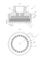
図1に、本発明の液化消火剤用噴射ヘッドの第1実施例を示す。
この液化消火剤用噴射ヘッド1は、液化消火剤を使用する消火設備において消火対象区画に液化消火剤を放出するために設置される噴射ヘッド1であって、液化消火剤を供給する配管(図示省略)が接続される噴射ヘッド本体2と、噴射ヘッド本体2に配設された、液化消火剤が通過するオリフィス31を形成したオリフィス板3と、オリフィス31の出口部に配設されたブロック形状の多孔質部材4と、多孔質部材4のオリフィス31の出口部の反対側の端面に当接して配設されたバッフルプレート5とを備えてなり、バッフルプレート5が、少なくとも多孔質部材4の端面のオリフィス31の外接円31cの投影面積部分を覆うようにするとともに、噴射ヘッド本体2とバッフルプレート5との間に形成された隙間6を通して液化消火剤を放出するようにしている。
ここで、噴射ヘッド1は、中心軸を回転対称とした円形に形成されている(以下の実施例も同様。)。
また、液化消火剤を供給する配管が接続される噴射ヘッド本体2には、配管を接続するための雌ねじ(又は雄ねじ)を形成するようにしている。FIG. 1 shows a first embodiment of the liquefied fire extinguishing agent injection head of the present invention.
This liquefied extinguishing
Here, the
Also, the injection head
ここで、この液化消火剤用噴射ヘッド1が対象とする液化消火剤には、以下(1)~(3)の消火剤が含まれる。
(1)一般的な保存状態で貯蔵容器に液体で保持される消火剤、例えば、ハロン1301等のハロゲン化物消火剤。
(2)噴射ヘッドから噴射される際に、噴射ヘッド直前の配管内で液体の状態の消火剤、例えば、HFC-227ea等。
(3)沸点が0℃以上の消火剤、例えば、ドデカフルオロ-2-メチルペンタン-3-オン(CF3CF2C(O)CF(CF3)2、沸点49.2℃、NFPA/ISO登録名「FK-5-1-12」)等。Here, the liquefied fire extinguishing agent targeted by the liquefied fire extinguishing
(1) A fire extinguishing agent that is kept liquid in a storage container under typical storage conditions, for example, a halide fire extinguishing agent such as Halon 1301;
(2) A fire extinguishing agent such as HFC-227ea that is in a liquid state in the pipe immediately before the ejection head when it is ejected from the ejection head.
(3) Extinguishing agents with a boiling point of 0°C or higher, such as dodecafluoro-2-methylpentan-3-one (CF 3 CF 2 C(O)CF(CF 3 ) 2 , boiling point 49.2°C, NFPA/ISO Registered name "FK-5-1-12"), etc.
この場合において、オリフィス板3は、中心に1個又は複数個(本実施例においては、6個。)のオリフィス31を等角度間隔に形成した円盤形状のもので、噴射ヘッド本体2の内部空間に形成した段部21に、例えば、段部21及びオリフィス板3の周面に形成したねじを介して、着脱可能に配設するようにしている。これにより、複数種類のオリフィス31を形成したオリフィス板3を設置場所等の条件に応じて選択することができるようにしている。
In this case, the
ブロック形状の多孔質部材4は、一体構造のもので構成するほか、本実施例に示すように、複数の多孔質部材41、42を積層した分割構造のもので構成することができる。
The block-shaped
ブロック形状の多孔質部材4は、形状保持性能の高い、すなわち、液化消火剤の放出圧力で変形等を起こさない無機材料(金属、金属の酸化物、金属の水酸化物等)を好適に用いることができ、3次元の網目状組織体からなる多孔質金属材料(住友電気工業社製「セルメット」(登録商標名))をより好適に用いることができる。
The block-shaped
多孔質部材4の空隙の孔径は、全体を均質な材料で構成するほか、液化消火剤の流動方向に沿って変化させた材料、より具体的には、空隙の孔径が液化消火剤の流動方向に沿って順次小さくなる材料で構成することができ、例えば、本実施例においては、液化消火剤の流動方向上流側の多孔質部材41の空隙の孔径よりも、下流側の多孔質部材42の空隙の孔径が小さくなるような材料で構成することができる。
このように、多孔質部材4の空隙の孔径を、液化消火剤の流動方向に沿って小さくなるようにすることにより、ブロック形状の多孔質部材内を流動する液化消火剤を均一に拡散させることができる。The pore diameters of the pores of the
In this way, the liquefied fire extinguishing agent flowing in the block-shaped porous member can be uniformly diffused by making the pore size of the pores of the
そして、多孔質部材4は、一体構造、分割構造のいずれの場合も、多孔質部材4の一方側の端面が噴射ヘッド本体2(本実施例においては、オリフィス板3を含む。以下の他の実施例においても同様。)に接して配設することで、オリフィス31の出口部に配設されるようにしている。
また、多孔質部材4の他方側の端面、すなわち、多孔質部材4のオリフィス31の出口部の反対側の端面には、バッフルプレート5が当接するようにしている。The
A
ところで、本実施例においては、オリフィス板3及び多孔質部材4は、1段構造としたが、図2に示す変形実施例のように、オリフィス板3及び多孔質部材4の上流側に、オリフィス31Aを形成したオリフィス板3A及び多孔質部材4Aを配設することによって、2段構造(又は3段以上の多段構造)とすることもできる。
これにより、噴射ヘッド本体2の内部での液化消火剤の均一な拡散特性を改善することができる。
また、図2に示す変形実施例においては、オリフィス板3Aを、噴射ヘッド本体2の配管との接続部側の開口を通して、噴射ヘッド本体2に着脱可能に構成するようにしている(後述の図6、図9、図11、図14及び図15に示す実施例のオリフィス板3も同様。)。
これにより、噴射ヘッド本体2に多孔質部材4を組み付けた状態で在庫として保管しておき、出荷時に、噴射ヘッドから放出される液化消火剤消火剤の流量に対応したオリフィス板3A(オリフィス板3)を、噴射ヘッド本体2の配管との接続部側の開口を介して、噴射ヘッド本体2に装着するようにすることができる。そして、これにより、一般的な噴射ヘッドと比べて大型化するこれら実施例の噴射ヘッドを在庫として保管しやすくすることによって、保管場所の制約やコスト上昇の問題を解消しながら、噴射ヘッドの出荷を迅速に行うことができるようにすることができる。By the way, in this embodiment, the
Thereby, the uniform diffusion characteristics of the liquefied fire extinguishing agent inside the
Further, in the modified embodiment shown in FIG. 2, the
As a result, the
バッフルプレート5は、多孔質部材4の中心部を貫通するねじ部51(ねじ部51は、バッフルプレート5に一体に形成するほか、図3に示す変形実施例のように、別部材(ねじ部材8)で構成することができる。また、ねじ部51をねじ部材8で構成する場合は、1本又は複数本のねじ部材8を用いることができる。)によってオリフィス板3に螺着する(又はねじ部51をボルト及びナットで構成してオリフィス板3に締結する)ことにより、噴射ヘッド本体2に固定するようにしている。
そして、バッフルプレート5は、多孔質部材4の他方側の端面に当接することで、少なくとも多孔質部材4の端面のオリフィス31の外接円31c(本実施例においては、6個のオリフィス31の共通外接円31c)の投影面積部分を覆うようにし、当該部分から液化消火剤が放出されないようにするとともに、噴射ヘッド本体2とバッフルプレート5との間に形成された隙間6を通して液化消火剤を放出するようにしている。The
The
噴射ヘッド本体2とバッフルプレート5との間に形成する隙間6は、本実施例においては、出口側が若干拡開した円環状のスリットで構成するようにし、これにより、液化消火剤の放出形態がオリフィス31の軸方向(噴射ヘッド本体2の中心軸の軸方向)と同方向の円柱状となるようにしている。
ここで、円環状のスリットからなる隙間6の幅寸法Dは、液化消火剤用噴射ヘッド1の能力や対象とする液化消火剤によって適宜設定することができるが、好ましくは、30mm以下、より好ましくは、1mm~10mm程度で、隙間6の内径と外径の比が0.70以上になるように設定するようにする。
また、円環状のスリットからなる隙間6(バッフルプレート5)の厚さ方向の寸法Tは、液化消火剤の放出方向が特定方向に規制することができるように、好ましくは、30mm以下、より好ましくは、1mm~10mm程度に設定するようにする。
これにより、液化消火剤のオリフィス31の軸方向(噴射ヘッド本体2の中心軸の軸方向)と同方向の拡散特性を改善することができる。In this embodiment, the
Here, the width dimension D of the
In addition, the dimension T in the thickness direction of the gap 6 (baffle plate 5) formed by the annular slit is preferably 30 mm or less, more preferably 30 mm or less, so that the discharge direction of the liquefied fire extinguishing agent can be regulated in a specific direction. should be set to about 1 mm to 10 mm.
As a result, the diffusion characteristics of the liquefied fire extinguishing agent in the same direction as the axial direction of the orifice 31 (the axial direction of the central axis of the ejection head body 2) can be improved.
この液化消火剤用噴射ヘッド1によれば、オリフィス31を介して供給された液化消火剤が、ブロック形状の多孔質部材4内をショートパスすることなく流動しながら拡散し、かつ、バッフルプレート5によって液化消火剤の放出方向が特定方向に規制することで、液化消火剤の拡散特性や気化特性を改善して、液化消火剤を広い範囲に拡散、気化させることができる。これにより、1つの噴射ヘッド1でカバーできる消火対象範囲を大きくすることができる。
また、液化消火剤が、ブロック形状の多孔質部材4内をショートパスすることなく流動しながら拡散して放出されるため、液化消火剤の放出時に発生する騒音を低減することができる。According to this liquefied fire
In addition, since the liquefied fire extinguishing agent is diffused while flowing through the block-shaped
ところで、上記第1実施例においては、噴射ヘッド本体2とバッフルプレート5との間に形成する隙間6を、出口側が若干拡開した円環状のスリットで構成するようにしたが、隙間6の形状は、これに限定されず、出口側が拡開しないストレート形状の円環状のスリットで構成するようにすることにより、液化消火剤のオリフィス31の軸方向(噴射ヘッド本体2の中心軸の軸方向)と同方向の拡散特性を改善して、液化消火剤をより広い範囲に拡散、気化させるようにすることができる。
By the way, in the first embodiment, the
また、図4に示す変形実施例のように、噴射ヘッド本体2側をストレート形状とし、バッフルプレート5側を第1実施例より大きく拡開した円環状のスリットで構成することにより、円柱状に放出される液化消火剤の中心方向への拡散特性を改善することができる。
Further, as in the modified embodiment shown in FIG. 4, the side of the
また、上記第1実施例においては、バッフルプレート5を、多孔質部材4の中心部を貫通するねじ部51によってオリフィス板3に螺着することにより、噴射ヘッド本体2に固定するようにしたが、図5及び図6に示す変形実施例のように、バッフルプレート5を、立ち上がり部52を備えたキャップ構造とし、噴射ヘッド本体2に螺合して固定するようにすることができる。
そして、図5及び図6に示す変形実施例において、バッフルプレート5は、多孔質部材4の他方側の端面に当接することで、少なくとも多孔質部材4の端面のオリフィス31の外接円31c(本実施例においては、6個のオリフィス31の共通外接円31c)の投影面積部分を覆うようにし、当該部分から液化消火剤が放出されないようにするとともに、バッフルプレート5のオリフィス31の外接円31c(本実施例においては、6個のオリフィス31の共通外接円31c)の投影面積部分の外側に形成された透孔7を通して液化消火剤を放出するようにしている。In addition, in the first embodiment, the
In the modified embodiment shown in FIGS. 5 and 6, the
透孔7は、円環状に配列した長孔(図5に示す変形実施例)や円孔(図6に示す変形実施例)で構成するようにし、これにより、液化消火剤の放出形態がオリフィス31の軸方向(噴射ヘッド本体2の中心軸の軸方向)と同方向の円柱状となるようにしている。
ここで、透孔7の幅寸法Dや形成間隔は、液化消火剤用噴射ヘッド1の能力や対象とする液化消火剤によって適宜設定することができるが、透孔7の幅寸法Dは、好ましくは、30mm以下、より好ましくは、1mm~10mm程度で、複数の透孔7に共通に接する小径円71の径と大径円72の径の比が0.70以上になるように設定するようにする。
また、透孔7(バッフルプレート5)の厚さ方向の寸法Tは、液化消火剤の放出方向が特定方向に規制することができるように、好ましくは、30mm以下、より好ましくは、1mm~10mm程度に設定するようにする。
これにより、液化消火剤のオリフィス31の軸方向(噴射ヘッド本体2の中心軸の軸方向)と同方向の拡散特性を改善することができる。The through-
Here, the width dimension D and the formation interval of the through
In addition, the dimension T in the thickness direction of the through hole 7 (baffle plate 5) is preferably 30 mm or less, more preferably 1 mm to 10 mm, so that the discharge direction of the liquefied fire extinguishing agent can be regulated in a specific direction. set to a certain degree.
As a result, the diffusion characteristics of the liquefied fire extinguishing agent in the same direction as the axial direction of the orifice 31 (the axial direction of the central axis of the ejection head body 2) can be improved.
ところで、上記各実施例は、液化消火剤の放出形態がオリフィス31の軸方向(噴射ヘッド本体2の中心軸の軸方向)と同方向の円柱状となるようにしているが、液化消火剤の放出形態は、これに限定されず、例えば、図7に示す本発明の液化消火剤用噴射ヘッドの第2実施例のように、隙間6に位置する噴射ヘッド本体2及びバッフルプレート5を円錐状に切除した切欠部22、53を形成することによって、液化消火剤の放出形態がオリフィス31の軸方向と所定の角度(本実施例においては、約65°に設定しているが、この角度は、0~90°の任意の角度に設定することができる。)を有する円錐状となるようにすることもできる。
ここで、円環状のスリットからなる隙間6の幅寸法Dは、液化消火剤用噴射ヘッド1の能力や対象とする液化消火剤によって適宜設定することができるが、好ましくは、30mm以下、より好ましくは、1mm~10mm程度に設定するようにする。
これにより、液化消火剤のオリフィス31の軸方向と同方向の拡散特性を改善するとともに、さらに、液化消火剤のオリフィス31の軸方向と直交する方向成分の拡散特性を持たせることによって、液化消火剤をより広い範囲に拡散、気化させることができる。By the way, in each of the above embodiments, the liquefied fire extinguishing agent is discharged in a columnar shape in the same direction as the axial direction of the orifice 31 (the axial direction of the central axis of the jet head main body 2). The ejection form is not limited to this. By forming the
Here, the width dimension D of the
As a result, the diffusion characteristics of the liquefied fire extinguishing agent in the same direction as the axial direction of the
このほか、液化消火剤の放出形態としては、例えば、図8に示す本発明の液化消火剤用噴射ヘッドの第3実施例のように、隙間6を噴射ヘッド本体2の下端側に形成することによって、液化消火剤の放出形態がオリフィス31の軸方向と直交する方向の円盤状となるようにすることもできる。
ここで、円環状のスリットからなる隙間6の幅寸法Dは、液化消火剤用噴射ヘッド1の能力や対象とする液化消火剤によって適宜設定することができるが、好ましくは、30mm以下、より好ましくは、1mm~10mm程度に設定するようにする。
また、円環状のスリットからなる隙間6の厚さ方向の寸法Tは、液化消火剤の放出方向が特定方向に規制することができるように、好ましくは、30mm以下、より好ましくは、1mm~10mm程度に設定するようにする。
これにより、液化消火剤のオリフィス31の軸方向と直交する方向の拡散特性を改善して、液化消火剤をより広い範囲に拡散、気化させることができる。In addition, as a discharge form of the liquefied fire extinguishing agent, for example, as in the third embodiment of the liquefied fire extinguishing agent ejection head of the present invention shown in FIG. , the liquefied fire extinguishing agent can be discharged in a disk-like shape in a direction orthogonal to the axial direction of the
Here, the width dimension D of the
In addition, the dimension T in the thickness direction of the
As a result, the diffusion characteristics of the liquefied fire extinguishing agent in the direction orthogonal to the axial direction of the
ところで、本実施例においては、オリフィス板3及び多孔質部材4は、1段構造としたが、図9に示す変形実施例のように、オリフィス板3及び多孔質部材4の上流側に、オリフィス31Aを形成したオリフィス板3A及び多孔質部材4Aを配設することによって、2段構造(又は3段以上の多段構造)とすることもできる。
これにより、噴射ヘッド本体2の内部での液化消火剤の均一な拡散特性を改善することができる。By the way, in this embodiment, the
Thereby, the uniform diffusion characteristics of the liquefied fire extinguishing agent inside the
また、バッフルプレート5は、多孔質部材4の中心部を貫通するねじ部51によってオリフィス板3に螺着するようにしているが、これに代えて、ねじ部材8を用いて噴射ヘッド本体2とバッフルプレート5とを締結するようにすることもできる。
具体的には、図10に示す変形実施例のように、噴射ヘッド本体2及びバッフルプレート5に外周側に部分的に突出する膨出部23、54を形成し、この膨出部23、54の位置でねじ部材8を用いて噴射ヘッド本体2とバッフルプレート5とを締結するようにすることができる。
ここで、ねじ部材8の位置には、必要に応じて、スペーサ81を介在させることができる。
また、図11に示す変形実施例のように、多孔質部材4を貫通するねじ部材8を用いて、噴射ヘッド本体2とバッフルプレート5とを締結するようにすることができる。
ここで、噴射ヘッド本体2の外周面には、液化消火剤を供給する配管(図示省略)に噴射ヘッド本体2を接続する際に、締付具(図示省略)を装着するための操作用穴24を形成するようにしている。In addition, the
Specifically, as in the modified embodiment shown in FIG. 10, the ejection head
Here, a spacer 81 can be interposed at the position of the
Further, as in a modified embodiment shown in FIG. 11, the ejecting head
Here, on the outer peripheral surface of the
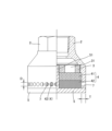
ところで、液化消火剤の放出形態としては、図12-1に示す変形実施例のように、液化消火剤の放出形態がオリフィス31の軸方向と直交する方向の所定の角度αを有する扇状となるようにすることもできる。
この液化消火剤の放出形態は、噴射ヘッド本体2とバッフルプレート5との間に形成された液化消火剤を放出する円環状のスリットからなる隙間6の一部を閉鎖部材62によって閉鎖することによって容易に得ることができる。
角度αは、噴射ヘッド1の設置形態等に合わせて任意の角度(例えば、30°~330°の範囲)に設定することができる。
これにより、液化消火剤のオリフィス31の軸方向と直交する方向の拡散特性を改善して、液化消火剤を特定の方向に拡散、気化させることができるようになるため、例えば、消火区画を構成する部屋の入り隅部に設置される噴射ヘッド1に好適に使用することができる。
この場合、図12-2に示す変形実施例のように、等角度間隔に形成(図12-1に示す変形実施例においては、60°間隔で6個形成。)していたオリフィス31を、偏在するように形成(例えば、隙間6を形成した側のみ60°間隔で3個形成。)することができる。
これにより、簡単に液化消火剤の放出特性を種々に変化、調整することができる。By the way, as for the discharge form of the liquefied fire extinguishing agent, as in the modified embodiment shown in FIG. You can also make
The liquefied fire extinguishing agent is discharged by partially closing the
The angle α can be set to any angle (for example, in the range of 30° to 330°) according to the installation form of the
As a result, the diffusion characteristics of the liquefied fire extinguishing agent in the direction orthogonal to the axial direction of the
In this case, the
This makes it possible to easily change and adjust the discharge characteristics of the liquefied fire extinguishing agent.
さらに、図13-1及び図13-2(a)に示す変形実施例のように、液化消火剤の放出形態を扇状にするための噴射ヘッド本体2とバッフルプレート5との間に形成された隙間6の両端を形成する区画壁面(閉鎖部材62の端面62a)を、隙間6の反対側(奥側)に向かう傾斜面に形成し、この傾斜面(閉鎖部材62の端面62a)と多孔質部材4の外周面との間に楔形の隙間6aが形成されるようにすることができる。
この場合、傾斜面(閉鎖部材62の端面62a)は、多孔質部材4の外周面に外接する形状に形成することが望ましい。
これにより、楔形の隙間6aから傾斜面(閉鎖部材62の端面62a)に沿った液化消火剤(気化状態)の流れを発生させ、液化消火剤(気化状態)の半径方向の流れの方向を変更させることで、多孔質部材4の大気開放面積を増大させることができ(液化消火剤の放出角度を制限する角度βに対して、多孔質部材4の大気開放面積の基準は、角度βより大きな角度αを基準とすることができる。)、液化消火剤のオリフィスの軸方向と直交する方向の拡散特性を一層改善することができる。
この場合、傾斜面(閉鎖部材62の端面62a)の形状は、図13-1及び図13-2(a)に示す変形実施例の平面形状に限定されず、図13-2(b)~(e)に示す変形実施例のような、曲面形状にすることもできる。
ここで、図13-2(b)は、半円形状の開口が開くように、図13-2(c)は、それより小さい半円形状の開口が開くように、図13-2(d)は、1/4円形状の開口が開くように、図13-2(e)は、円形状の開口が開くように、閉鎖部材62の端面62aを加工するようにしている。
このように、傾斜面(閉鎖部材62の端面62a)の形状を変えることにより、開口の形状や面積を変化させることができ、これにより、本体形状を大きく変更させることなく、液化消火剤の放出特性を種々に変化、調整することができる。Furthermore, as in the modified embodiment shown in FIGS. 13-1 and 13-2(a), a Partition wall surfaces (end surfaces 62a of the closing member 62) forming both ends of the
In this case, the inclined surface (the
As a result, the liquefied fire extinguishing agent (vaporized state) flows from the wedge-shaped
In this case, the shape of the inclined surface (the
Here, in FIG. 13-2(b), a semicircular opening is opened, in FIG. 13-2(c), a smaller semicircular opening is opened, and in FIG. ), the
Thus, by changing the shape of the inclined surface (the
また、液化消火剤を放出する円環状のスリットからなる隙間6に代えて、オリフィス31の外接円(本実施例においては、6個のオリフィス31の共通外接円)の投影面積部分の外側に形成された透孔7を通して液化消火剤を放出するようにすることもできる。
透孔7は、図14に示す変形実施例のように、立ち上がり部52を備えたキャップ構造としたバッフルプレート5の立ち上がり部52に形成した円環状に配列した長孔や、図15に示す変形実施例のように、立ち上がり部52を備えたキャップ構造としたバッフルプレート5の立ち上がり部52に形成した円環状に複数段(図示の例では、2段。このように多段とすることで、好適な隙間幅を保ちつつ、多孔質部材4の大気開放面積を増大させることができる。)に配列した長孔や、図16に示す変形実施例のように、噴射ヘッド本体2の下部(下方に配設した多孔質部材42の外周面が面する部分。)に形成した円環状に配列した円孔で構成することができる。
ここで、透孔7の幅寸法Dや形成間隔は、液化消火剤用噴射ヘッド1の能力や対象とする液化消火剤によって適宜設定することができるが、透孔7の幅寸法Dは、好ましくは、30mm以下、より好ましくは、1mm~10mm程度に設定するようにする。
また、透孔7(バッフルプレート5の立ち上がり部52や噴射ヘッド本体2)の厚さ方向の寸法Tは、液化消火剤の放出方向が特定方向に規制することができるように、好ましくは、30mm以下、より好ましくは、1mm~10mm程度に設定するようにする。
これにより、液化消火剤のオリフィス31の軸方向と直交する方向の拡散特性を改善して、液化消火剤をより広い範囲に拡散、気化させることができる。Further, instead of the
The through
Here, the width dimension D and the formation interval of the through
In addition, the dimension T in the thickness direction of the through hole 7 (the rising
As a result, the diffusion characteristics of the liquefied fire extinguishing agent in the direction orthogonal to the axial direction of the
ところで、上記各実施例においては、液化消火剤を放出する方向を1方向に設定するようにしたが、上記各実施例を組み合わせることによって、液化消火剤を放出する方向を2方向にすることができる。
例えば、図17に示す本発明の液化消火剤用噴射ヘッドの第4実施例のように、図1に記載した第1実施例と、図16に記載した第3実施例の変形実施例とを組み合わせることによって、液化消火剤を、噴射ヘッド本体2とバッフルプレート5との間に形成する隙間6から、オリフィス31の軸方向(噴射ヘッド本体2の中心軸の軸方向)と同方向の円柱状となるように放出するとともに、噴射ヘッド本体2の下部(下方に配設した多孔質部材42の外周面が面する部分。)に形成した円環状に配列した円孔で構成した透孔7から、オリフィス31の軸方向と直交する方向の円盤状となるように放出するようにしている。
これにより、液化消火剤のオリフィス31の軸方向と同方向及び直交する方向の拡散特性を改善して、液化消火剤をより広い範囲に拡散、気化させることができる。By the way, in each of the above embodiments, the direction in which the liquefied fire extinguishing agent is discharged is set to one direction. can.
For example, like the fourth embodiment of the liquefied fire extinguishing agent injection head of the present invention shown in FIG. 17, the first embodiment shown in FIG. 1 and the modified embodiment of the third embodiment shown in FIG. By combining, the liquefied fire extinguishing agent is discharged from the
As a result, the diffusion characteristics of the liquefied fire extinguishing agent in the axial direction of the
以上、本発明の液化消火剤用噴射ヘッドについて、複数の実施例に基づいて説明したが、本発明は上記実施例に記載した構成に限定されるものではなく、各実施例に記載した構成を適宜組み合わせる等、その趣旨を逸脱しない範囲において適宜その構成を変更することができるものである。 The liquefied fire extinguishing agent injection head of the present invention has been described above based on a plurality of examples. The configuration can be changed as appropriate without departing from the spirit of the invention, such as by combining them as appropriate.
本発明の液化消火剤用噴射ヘッドは、液化消火剤の拡散特性や気化特性が良く、1つの噴射ヘッドでカバーできる消火対象範囲を大きくすることができるとともに、騒音の低減率を高めることができることから、液化消火剤を使用する消火設備において消火対象区画に液化消火剤を放出するために設置される噴射ヘッドに広く用いることができ、適用対象も、新設の消火設備に限定されず、噴射ヘッドを交換するだけで、既設の消火設備にも適用することができる。 The liquefied fire extinguishing agent injection head of the present invention has good diffusion characteristics and vaporization characteristics of the liquefied fire extinguishing agent, and can increase the fire extinguishing target range that can be covered by one injection head, and can increase the noise reduction rate. Therefore, it can be widely used for the injection head installed to discharge the liquefied extinguishing agent to the fire extinguishing target section in the fire extinguishing equipment that uses the liquefied extinguishing agent, and the application target is not limited to newly installed fire extinguishing equipment. It can also be applied to existing fire extinguishing equipment by simply replacing the
1 噴射ヘッド
2 噴射ヘッド本体
21 段部
22 切欠部
23 膨出部
24 操作用穴
3 オリフィス板
31 オリフィス
4 多孔質部材
41 多孔質部材
42 多孔質部材
5 バッフルプレート
51 ねじ部
52 立ち上がり部
53 切欠部
54 膨出部
6 隙間
7 透孔
8 ねじ部材
81 スペーサREFERENCE SIGNS
Claims (5)
Applications Claiming Priority (3)
| Application Number | Priority Date | Filing Date | Title |
|---|---|---|---|
| JP2018187665 | 2018-10-02 | ||
| JP2018187665 | 2018-10-02 | ||
| PCT/JP2019/038588 WO2020071329A1 (en) | 2018-10-02 | 2019-09-30 | Spray head for liquefied fire-extinguishing agent |
Publications (3)
| Publication Number | Publication Date |
|---|---|
| JPWO2020071329A1 JPWO2020071329A1 (en) | 2021-09-16 |
| JPWO2020071329A5 JPWO2020071329A5 (en) | 2022-10-05 |
| JP7299629B2 true JP7299629B2 (en) | 2023-06-28 |
Family
ID=70055552
Family Applications (1)
| Application Number | Title | Priority Date | Filing Date |
|---|---|---|---|
| JP2020550429A Active JP7299629B2 (en) | 2018-10-02 | 2019-09-30 | Injection head for liquefied extinguishing agent |
Country Status (11)
| Country | Link |
|---|---|
| US (1) | US11369978B2 (en) |
| EP (2) | EP3815752B1 (en) |
| JP (1) | JP7299629B2 (en) |
| KR (1) | KR20210063278A (en) |
| CN (1) | CN112312975B (en) |
| CA (1) | CA3104466A1 (en) |
| ES (1) | ES2947441T3 (en) |
| PH (1) | PH12020552242A1 (en) |
| SG (1) | SG11202012389XA (en) |
| TW (1) | TWI799647B (en) |
| WO (1) | WO2020071329A1 (en) |
Families Citing this family (2)
| Publication number | Priority date | Publication date | Assignee | Title |
|---|---|---|---|---|
| US11060460B1 (en) * | 2019-04-01 | 2021-07-13 | Marine Turbine Technologies, LLC | Fuel distribution system for gas turbine engine |
| CN112206448A (en) * | 2020-09-23 | 2021-01-12 | 诸佳枫 | Water spraying gun head capable of reducing noise to the maximum extent during water spraying |
Citations (4)
| Publication number | Priority date | Publication date | Assignee | Title |
|---|---|---|---|---|
| EP1151800A2 (en) | 2000-05-05 | 2001-11-07 | Vesta Srl | Silenced nozzle for discharge of extinguishing gas |
| JP2011125673A (en) | 2009-11-02 | 2011-06-30 | Koatsu Co Ltd | Jet head having silencing function for gas-based fire extinguishing system |
| JP2011255152A (en) | 2009-10-23 | 2011-12-22 | Air Water Safety Service Inc | Gas fire-extinguishing facility |
| JP5276730B1 (en) | 2012-03-21 | 2013-08-28 | 株式会社コーアツ | Ejection head with a sound deadening function for gas fire extinguishing equipment |
Family Cites Families (14)
| Publication number | Priority date | Publication date | Assignee | Title |
|---|---|---|---|---|
| US3022014A (en) * | 1958-11-12 | 1962-02-20 | Stephen A Young | Shower head |
| JPS543036Y2 (en) * | 1976-06-07 | 1979-02-09 | ||
| US5404957A (en) * | 1993-10-18 | 1995-04-11 | Mccormack; Pat | Fire retardant foam generator |
| US20050001065A1 (en) * | 2001-08-01 | 2005-01-06 | Kidde-Fenwal, Inc. | Nozzle apparatus and method for atomizing fluids |
| US6763894B2 (en) * | 2001-08-01 | 2004-07-20 | Kidde-Fenwal, Inc. | Clean agent fire suppression system and rapid atomizing nozzle in the same |
| CN200951280Y (en) * | 2006-09-06 | 2007-09-26 | 南京消防器材股份有限公司 | Nozzle used specially for low pressure carbon dioxide fire fighting system |
| GB2478104B (en) * | 2008-12-18 | 2012-10-03 | Utc Fire & Security Corp | Atomizing nozzle for a fire suppression system |
| EP2425877B1 (en) * | 2009-04-27 | 2017-09-06 | Hochiki Corporation | Fire prevention equipment |
| TWI566804B (en) * | 2012-02-21 | 2017-01-21 | 高壓股份有限公司 | Injection head having silencing function for gas-type fire extinguisher |
| US9597537B2 (en) * | 2012-05-03 | 2017-03-21 | Koatsu Co., Ltd. | Injection head having silencing function for gas type fire extinguisher |
| US11389678B2 (en) * | 2015-12-04 | 2022-07-19 | Tyco Fire Products Lp | Low pressure drop acoustic suppressor nozzle for inert gas discharge system |
| US20200353300A1 (en) * | 2016-12-26 | 2020-11-12 | Koatsu Co., Ltd. | Injection head having silencing function for gas-type fire extinguisher and method for storing and assembling thereof |
| CN106861101A (en) * | 2017-04-11 | 2017-06-20 | 广州广消阀门有限公司 | A kind of fluorinated ketone fire-smothering gear |
| CA3064175A1 (en) * | 2017-05-19 | 2018-11-22 | Koatsu Co., Ltd. | Injection head for liquefied fire-extinguishing agent |
-
2019
- 2019-09-20 TW TW108133940A patent/TWI799647B/en active
- 2019-09-30 KR KR1020207035922A patent/KR20210063278A/en unknown
- 2019-09-30 WO PCT/JP2019/038588 patent/WO2020071329A1/en active Application Filing
- 2019-09-30 JP JP2020550429A patent/JP7299629B2/en active Active
- 2019-09-30 CA CA3104466A patent/CA3104466A1/en active Pending
- 2019-09-30 EP EP19869477.0A patent/EP3815752B1/en active Active
- 2019-09-30 US US17/251,540 patent/US11369978B2/en active Active
- 2019-09-30 ES ES19869477T patent/ES2947441T3/en active Active
- 2019-09-30 EP EP23158146.3A patent/EP4205818B1/en active Active
- 2019-09-30 CN CN201980042481.3A patent/CN112312975B/en active Active
- 2019-09-30 SG SG11202012389XA patent/SG11202012389XA/en unknown
-
2020
- 2020-12-21 PH PH12020552242A patent/PH12020552242A1/en unknown
Patent Citations (4)
| Publication number | Priority date | Publication date | Assignee | Title |
|---|---|---|---|---|
| EP1151800A2 (en) | 2000-05-05 | 2001-11-07 | Vesta Srl | Silenced nozzle for discharge of extinguishing gas |
| JP2011255152A (en) | 2009-10-23 | 2011-12-22 | Air Water Safety Service Inc | Gas fire-extinguishing facility |
| JP2011125673A (en) | 2009-11-02 | 2011-06-30 | Koatsu Co Ltd | Jet head having silencing function for gas-based fire extinguishing system |
| JP5276730B1 (en) | 2012-03-21 | 2013-08-28 | 株式会社コーアツ | Ejection head with a sound deadening function for gas fire extinguishing equipment |
Also Published As
| Publication number | Publication date |
|---|---|
| EP3815752A4 (en) | 2022-02-09 |
| TW202026040A (en) | 2020-07-16 |
| KR20210063278A (en) | 2021-06-01 |
| CN112312975B (en) | 2022-10-18 |
| EP3815752A1 (en) | 2021-05-05 |
| US20210252530A1 (en) | 2021-08-19 |
| EP3815752C0 (en) | 2023-06-07 |
| WO2020071329A1 (en) | 2020-04-09 |
| SG11202012389XA (en) | 2021-01-28 |
| EP4205818A1 (en) | 2023-07-05 |
| ES2947441T3 (en) | 2023-08-09 |
| CA3104466A1 (en) | 2020-04-09 |
| JPWO2020071329A1 (en) | 2021-09-16 |
| EP3815752B1 (en) | 2023-06-07 |
| PH12020552242A1 (en) | 2021-06-28 |
| US11369978B2 (en) | 2022-06-28 |
| EP4205818B1 (en) | 2024-02-14 |
| CN112312975A (en) | 2021-02-02 |
| TWI799647B (en) | 2023-04-21 |
Similar Documents
| Publication | Publication Date | Title |
|---|---|---|
| JP7299629B2 (en) | Injection head for liquefied extinguishing agent | |
| US20050001065A1 (en) | Nozzle apparatus and method for atomizing fluids | |
| US20020027143A1 (en) | Clean agent fire suppression system and rapid atomizing nozzle in the same | |
| TWI732078B (en) | Injection head having silencing function for gas-type fire extinguisher and storaging and assembling method of the same | |
| US10258816B2 (en) | Injection head having silencing function for gas-type fire extinguisher | |
| US6964307B1 (en) | Sprinklers | |
| WO2018212160A1 (en) | Spray head for liquefied fire-extinguishing agent | |
| JP2013192764A (en) | Spray head for gaseous fire extinguishing equipment having silencing function | |
| JPWO2020071329A5 (en) | ||
| RU2786611C2 (en) | Spraying head for liquid extinguishing agent | |
| US20210346742A1 (en) | Low noise nozzle assembly for fire suppression system | |
| JP3100870U (en) | Firefighting nozzle assembly | |
| JPH0654920A (en) | Fire fighting foam head | |
| JP2013192960A (en) | Spray head for gaseous fire extinguishing equipment having silencing function | |
| JPH088935B2 (en) | Fire extinguishing nozzle for powder fire extinguishing equipment |
Legal Events
| Date | Code | Title | Description |
|---|---|---|---|
| A521 | Request for written amendment filed |
Free format text: JAPANESE INTERMEDIATE CODE: A523 Effective date: 20220926 |
|
| A621 | Written request for application examination |
Free format text: JAPANESE INTERMEDIATE CODE: A621 Effective date: 20220926 |
|
| RD02 | Notification of acceptance of power of attorney |
Free format text: JAPANESE INTERMEDIATE CODE: A7422 Effective date: 20220926 |
|
| TRDD | Decision of grant or rejection written | ||
| A01 | Written decision to grant a patent or to grant a registration (utility model) |
Free format text: JAPANESE INTERMEDIATE CODE: A01 Effective date: 20230606 |
|
| A61 | First payment of annual fees (during grant procedure) |
Free format text: JAPANESE INTERMEDIATE CODE: A61 Effective date: 20230609 |
|
| R150 | Certificate of patent or registration of utility model |
Ref document number: 7299629 Country of ref document: JP Free format text: JAPANESE INTERMEDIATE CODE: R150 |