EP3814256B1 - Dispositif de pose de fond et procédé permettant la fabrication d'articles tubulaires pourvus au moins d'un fond - Google Patents
Dispositif de pose de fond et procédé permettant la fabrication d'articles tubulaires pourvus au moins d'un fond Download PDFInfo
- Publication number
- EP3814256B1 EP3814256B1 EP19735533.2A EP19735533A EP3814256B1 EP 3814256 B1 EP3814256 B1 EP 3814256B1 EP 19735533 A EP19735533 A EP 19735533A EP 3814256 B1 EP3814256 B1 EP 3814256B1
- Authority
- EP
- European Patent Office
- Prior art keywords
- piece
- transport
- tubing
- hose
- relative
- Prior art date
- Legal status (The legal status is an assumption and is not a legal conclusion. Google has not performed a legal analysis and makes no representation as to the accuracy of the status listed.)
- Active
Links
- 238000004519 manufacturing process Methods 0.000 title claims 2
- 238000000034 method Methods 0.000 description 7
- 230000008569 process Effects 0.000 description 3
- 230000004888 barrier function Effects 0.000 description 2
- 230000008859 change Effects 0.000 description 2
- 238000006073 displacement reaction Methods 0.000 description 2
- 239000000463 material Substances 0.000 description 2
- 230000005693 optoelectronics Effects 0.000 description 2
- 230000009471 action Effects 0.000 description 1
- 238000004026 adhesive bonding Methods 0.000 description 1
- 230000015572 biosynthetic process Effects 0.000 description 1
- 230000001419 dependent effect Effects 0.000 description 1
- 238000001514 detection method Methods 0.000 description 1
- 230000000694 effects Effects 0.000 description 1
- 230000005484 gravity Effects 0.000 description 1
- 239000002184 metal Substances 0.000 description 1
- 230000003068 static effect Effects 0.000 description 1
- 238000011144 upstream manufacturing Methods 0.000 description 1
- 239000002699 waste material Substances 0.000 description 1
Images

Classifications
-
- B—PERFORMING OPERATIONS; TRANSPORTING
- B65—CONVEYING; PACKING; STORING; HANDLING THIN OR FILAMENTARY MATERIAL
- B65H—HANDLING THIN OR FILAMENTARY MATERIAL, e.g. SHEETS, WEBS, CABLES
- B65H5/00—Feeding articles separated from piles; Feeding articles to machines
- B65H5/02—Feeding articles separated from piles; Feeding articles to machines by belts or chains, e.g. between belts or chains
- B65H5/021—Feeding articles separated from piles; Feeding articles to machines by belts or chains, e.g. between belts or chains by belts
-
- B—PERFORMING OPERATIONS; TRANSPORTING
- B31—MAKING ARTICLES OF PAPER, CARDBOARD OR MATERIAL WORKED IN A MANNER ANALOGOUS TO PAPER; WORKING PAPER, CARDBOARD OR MATERIAL WORKED IN A MANNER ANALOGOUS TO PAPER
- B31B—MAKING CONTAINERS OF PAPER, CARDBOARD OR MATERIAL WORKED IN A MANNER ANALOGOUS TO PAPER
- B31B70/00—Making flexible containers, e.g. envelopes or bags
- B31B70/02—Feeding or positioning sheets, blanks or webs
- B31B70/04—Feeding sheets or blanks
-
- B—PERFORMING OPERATIONS; TRANSPORTING
- B65—CONVEYING; PACKING; STORING; HANDLING THIN OR FILAMENTARY MATERIAL
- B65H—HANDLING THIN OR FILAMENTARY MATERIAL, e.g. SHEETS, WEBS, CABLES
- B65H9/00—Registering, e.g. orientating, articles; Devices therefor
- B65H9/06—Movable stops or gauges, e.g. rising and falling front stops
-
- B—PERFORMING OPERATIONS; TRANSPORTING
- B65—CONVEYING; PACKING; STORING; HANDLING THIN OR FILAMENTARY MATERIAL
- B65H—HANDLING THIN OR FILAMENTARY MATERIAL, e.g. SHEETS, WEBS, CABLES
- B65H9/00—Registering, e.g. orientating, articles; Devices therefor
- B65H9/16—Inclined tape, roller, or like article-forwarding side registers
- B65H9/163—Tape
-
- B—PERFORMING OPERATIONS; TRANSPORTING
- B31—MAKING ARTICLES OF PAPER, CARDBOARD OR MATERIAL WORKED IN A MANNER ANALOGOUS TO PAPER; WORKING PAPER, CARDBOARD OR MATERIAL WORKED IN A MANNER ANALOGOUS TO PAPER
- B31B—MAKING CONTAINERS OF PAPER, CARDBOARD OR MATERIAL WORKED IN A MANNER ANALOGOUS TO PAPER
- B31B2150/00—Flexible containers made from sheets or blanks, e.g. from flattened tubes
- B31B2150/001—Flexible containers made from sheets or blanks, e.g. from flattened tubes with square or cross bottom
- B31B2150/0014—Flexible containers made from sheets or blanks, e.g. from flattened tubes with square or cross bottom having their openings facing transversally to the direction of movement
-
- B—PERFORMING OPERATIONS; TRANSPORTING
- B31—MAKING ARTICLES OF PAPER, CARDBOARD OR MATERIAL WORKED IN A MANNER ANALOGOUS TO PAPER; WORKING PAPER, CARDBOARD OR MATERIAL WORKED IN A MANNER ANALOGOUS TO PAPER
- B31B—MAKING CONTAINERS OF PAPER, CARDBOARD OR MATERIAL WORKED IN A MANNER ANALOGOUS TO PAPER
- B31B2150/00—Flexible containers made from sheets or blanks, e.g. from flattened tubes
- B31B2150/003—Flexible containers made from sheets or blanks, e.g. from flattened tubes made from tubular sheets
-
- B—PERFORMING OPERATIONS; TRANSPORTING
- B31—MAKING ARTICLES OF PAPER, CARDBOARD OR MATERIAL WORKED IN A MANNER ANALOGOUS TO PAPER; WORKING PAPER, CARDBOARD OR MATERIAL WORKED IN A MANNER ANALOGOUS TO PAPER
- B31B—MAKING CONTAINERS OF PAPER, CARDBOARD OR MATERIAL WORKED IN A MANNER ANALOGOUS TO PAPER
- B31B2150/00—Flexible containers made from sheets or blanks, e.g. from flattened tubes
- B31B2150/20—Flexible containers made from sheets or blanks, e.g. from flattened tubes the longitudinal axes of the containers being perpendicular to the direction in which the sheets or blanks are fed
-
- B—PERFORMING OPERATIONS; TRANSPORTING
- B31—MAKING ARTICLES OF PAPER, CARDBOARD OR MATERIAL WORKED IN A MANNER ANALOGOUS TO PAPER; WORKING PAPER, CARDBOARD OR MATERIAL WORKED IN A MANNER ANALOGOUS TO PAPER
- B31B—MAKING CONTAINERS OF PAPER, CARDBOARD OR MATERIAL WORKED IN A MANNER ANALOGOUS TO PAPER
- B31B2160/00—Shape of flexible containers
- B31B2160/20—Shape of flexible containers with structural provision for thickness of contents
-
- B—PERFORMING OPERATIONS; TRANSPORTING
- B31—MAKING ARTICLES OF PAPER, CARDBOARD OR MATERIAL WORKED IN A MANNER ANALOGOUS TO PAPER; WORKING PAPER, CARDBOARD OR MATERIAL WORKED IN A MANNER ANALOGOUS TO PAPER
- B31B—MAKING CONTAINERS OF PAPER, CARDBOARD OR MATERIAL WORKED IN A MANNER ANALOGOUS TO PAPER
- B31B50/00—Making rigid or semi-rigid containers, e.g. boxes or cartons
- B31B50/006—Controlling; Regulating; Measuring; Improving safety
-
- B—PERFORMING OPERATIONS; TRANSPORTING
- B65—CONVEYING; PACKING; STORING; HANDLING THIN OR FILAMENTARY MATERIAL
- B65H—HANDLING THIN OR FILAMENTARY MATERIAL, e.g. SHEETS, WEBS, CABLES
- B65H2404/00—Parts for transporting or guiding the handled material
- B65H2404/20—Belts
- B65H2404/26—Particular arrangement of belt, or belts
- B65H2404/269—Particular arrangement of belt, or belts other arrangements
- B65H2404/2693—Arrangement of belts on movable frame
-
- B—PERFORMING OPERATIONS; TRANSPORTING
- B65—CONVEYING; PACKING; STORING; HANDLING THIN OR FILAMENTARY MATERIAL
- B65H—HANDLING THIN OR FILAMENTARY MATERIAL, e.g. SHEETS, WEBS, CABLES
- B65H2701/00—Handled material; Storage means
- B65H2701/10—Handled articles or webs
- B65H2701/19—Specific article or web
- B65H2701/191—Bags, sachets and pouches or the like
Definitions
- the invention relates to a floor laying device according to the preamble of patent claim 1 and a method according to the preamble of patent claim 5.
- a tube alignment table is used in known, generic devices for the individual alignment of the tube pieces, which are preferably made of paper.
- the piece of hose separated from a stack of hose pieces in a hose piece separating device is discharged to an alignment unit with which the hose pieces can be aligned.
- Such an alignment unit comprises a transport device with which the piece of hose can be transported in a transport direction at a transport speed, for example with a plurality of belts running parallel and in the transport direction.
- the belts have stops attached to the transport side.
- the stops are arranged at a distance of the machine cycle.
- At least one conveying element is arranged in the space between the belts, which can be designed as a belt and which is at an angle of inclination obliquely to the transport direction.
- These conveyor elements usually have one Speed increased compared to the transport speed, so that a difference speed to the transport speed is generated.
- the differential speed has a linear dependence on the transport speed. This applies to both the longitudinal and transverse directions, based on the piece of hose.
- a one-sided and vertically arranged conveyor belt is generally provided, which limits the lateral positions of the hose pieces. In general, it can be said that the piece of hose can be moved relative to the transport device by means of the conveying elements. In this way the piece of hose is aligned.
- an alignment about an axis of rotation means that a rotation takes place with a rotation angle of less than 20 degrees, in particular less than 10 degrees and preferably less than 5 degrees.
- the piece of hose Depending on the friction value of the piece of hose, it reaches the alignment stops sooner or later.
- the lateral alignment band is also reached early in some cases. It therefore happens that the alignment process has already been completed satisfactorily, but the piece of hose has not yet reached the end of an alignment section. Since the inclined conveying elements continue to act on the piece of hose, it continues to be pressed against the stops. It can happen that the pieces of hose are damaged, especially if they are made of very flexible material.
- US 6,352,148 B1 discloses a device or a method according to the preamble of claims 1 or 5.
- the object of the present invention is therefore to create a floor laying device for producing hose pieces provided with at least one bottom, which largely avoids damage to hose pieces during their alignment.
- the differential speed and/or the relative position of the conveying elements to the transport device can be changed, in particular controllable.
- the alignment process can be influenced in such a way that, for example, the implementation of the alignments is essentially ended when the piece of hose reaches the end of the alignment section.
- the easiest way to do this is to change or even control the differential speed.
- This allows the duration of the alignment process to be influenced so that at the end of the alignment section the load on the material is as low as possible.
- the conveying elements can be driven with their own drive or that a variably adjustable gear stage is provided between the main drive and the conveying elements. Particularly when conveying elements are arranged at an angle of inclination, despite this, The already completed alignments still have a force acting on the hose element.
- the relative position of the conveying elements to the transport direction can be changed, in particular controllable.
- This can mean, in particular, that the conveying elements can be adjusted vertically, in the transverse direction and/or with regard to the angle of inclination relative to the transport device, with the piece of hose being transported horizontally and in a direction that is essentially perpendicular to its longitudinal axis. If the vertical position can be changed, the conveying elements can be brought into a position below the transport device, so that the conveying elements come out of contact with the hose piece and the hose piece can no longer be moved relative to the transport device.
- the entire conveying elements are displaceable relative to the transport device and/or can be changed with regard to the angle of inclination.
- the transverse alignment and/or the rotational alignment can be carried out by independent movements of the conveying elements. The independence of the movements accordingly allows the alignments transverse to the transport direction and/or around the axis of rotation to be independent of the alignment distance, so that the start time and the end time of the alignments can be selected independently.
- a computing and control device is provided to which information on the actual position of the piece of hose relative to the transport device can be made available and to which the target positions of the piece of hose relative to the transport device are known, whereby in the event of deviations from the actual position to the target Position of the Hose piece with the computing and control device control commands for changing the differential speed and / or the relative position of the conveying elements can be generated.
- the actual position of each piece of hose is first recorded and this is then aligned, preferably individually, by appropriately controlling the conveying elements and/or changing their position, as already described above. After the actual position has been recorded, the size of the deviations from the target position can be determined using the computing and control device.
- control and computing device After determining the deviations, the control and computing device generates control commands that are sent to the conveying elements and/or their drives or actuators. This can be understood as controlling the alignment, whereby the control commands are generated and the conveying elements are activated in such a way that the piece of hose then assumes the desired position within tolerance limits.
- a computing and control device can be used to calculate a time at which the differential speed can be reduced to or less than zero and/or the relative position of the conveying elements to the transport device can be changed in such a way that the piece of hose rests relative to the transport device. This means that the action of the conveying elements on the piece of hose can be ended when the piece of hose should have reached the desired position within tolerance limits. In particular, the achievement of the target position is not verified, but merely calculated in advance. It is therefore not necessary to set up a complete control loop.
- the floor laying device comprises at least one sensor with which the actual position of the hose piece relative to the transport device can be detected.
- a sensor can be a light button, a light barrier, a camera or any other optoelectronic component that, for example, converts a change in contrast into an electrical signal and makes this accessible to a computing and control device.
- a camera in particular can be advantageous because it can take a picture of the... entire hose section can be recorded and the actual position of the hose section can be easily determined.
- At least one second sensor with which the actual position of the hose piece relative to the transport device can be detected at a time that is after the time at which the actual position of the hose piece relative to the transport device can be detected with a first sensor is.
- the current actual position can be checked again, for example while the alignment is being carried out, and the control commands can be adjusted again.
- the actual position can also be checked after alignment has been completed in order to detect alignment errors and, if necessary, to be able to reject the piece of hose. This means that an intact piece of hose can be fed to the floor laying device again, and incorrect formation of a floor, which would lead to waste, is avoided.
- the Figure 1 shows a piece of hose 101, which can be processed into a bag, with a bottom being formed on at least one end.
- the hose piece 101 has a longitudinal axis S, with the first open end 102 and the second open end 103 of the hose piece 101 being spaced apart from one another in the direction of the longitudinal axis S.
- the piece of hose is transported in the transport direction T through the floor laying device, whereby the Transport direction T is directed orthogonally to the longitudinal axis S. You can also say that the piece of hose is transported transversely to its longitudinal axis S.
- a first alignment direction is marked with the double arrow ⁇ Q, which represents the alignment in the transverse direction, the alignment preferably being perpendicular to the transport direction T.
- the third alignment direction is designated ⁇ R and represents the alignment that occurs through a rotation about a vertical axis 104.
- the vertical axis is the axis that is perpendicular to the plane of the hose piece or orthogonal to both the longitudinal axis S of the hose and to the transport direction T.
- the pivot point when rotating in the direction ⁇ R does not have to be at the center of gravity of the hose section, but can be at any point on the hose surface.
- FIG. 2 now shows a first embodiment of the invention.
- An alignment device 201 is shown, with which one or more pieces of hose can be transported in the transport direction T on a transport device 202 by means of conveyor belts 203 and which can be part of a floor laying device according to the invention.
- a piece of hose which is not shown in this figure, is considered to be well aligned if it rests against all cams 204 with the front edge related to the transport direction and also contacts the boundary 205 with a side edge.
- the boundary 205 can be a simple sheet metal, but is preferably also designed as a belt rotating at transport speed in order to avoid a deceleration effect when it comes into contact with the piece of hose.
- conveying elements are provided, which in the present figure are designed as belts 206 on which the piece of hose rests. These belts 206 preferably run on common rollers 207, at least one of which can be driven by its own drive, which is independent of the rest of the alignment device. The drive is not shown.
- the belts 206 run at a differential speed and at a higher absolute speed than that Conveyor belts 203 so that a piece of hose that is in contact with the belts 206 is pushed onto the cams 204.
- the prerequisite for this functionality is that the static friction between the conveying elements, here the belts 206, and the hose section is greater than the sliding friction between the transport device and the hose section. Only then is it possible to move the piece of hose relative to the transport device and thus align it.
- the belts 206 are arranged at an angle ⁇ relative to the transport direction T, so that a piece of hose is additionally pushed against the boundary 205.
- Upstream in the transport direction of the conveying elements are one or more sensors 210, which detect the current position of a piece of hose and forward position information to the computing and control unit 212 via the data line 211.
- the computing and control unit is intended and set up to compare this position information, i.e. the actual position, of a piece of hose with the target position and to generate control commands in the event of deviations.
- These control commands can be in the present exemplary embodiment Figure 2 serve to adjust the speed of the conveying elements 206 and thus adjust the differential speed between conveying elements relative to the transport device 202 if the deviations are outside tolerance limits.
- These control commands can therefore take place via a data line 213 of the drive device, not shown, which drives at least one of the rollers 207.
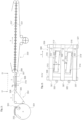
- the Figure 3 now shows a schematic representation of a floor laying device according to the invention.
- the floor laying device 300 initially comprises a separating device, which is illustrated here using the example of a so-called rotary feeder 301, with which a piece of hose 302 is removed from the stack of hose pieces 303.
- the piece of hose is peeled off from the underside of the stack of hose pieces.
- the function of such a rotary feeder is described in the publication, for example DE 32 14 342 A1 shown and explained.
- the isolated piece of hose is then handed over to a transfer conveyor 304.
- This can, for example, comprise several, in particular two, transport belts 305 that run parallel and are spaced apart in the direction of the tube's longitudinal axis and can be driven by at least one drive.
- transport speed can be varied independently of the transport speed of the floor layer, so that an alignment in the longitudinal direction can be carried out. If parallel transport belts are driven separately, they can also be driven at a differential speed so that alignment in the direction of rotation can be carried out.
- the transfer conveyor 304 is followed by an alignment device 306, which is in the Figure 4 is also shown in the top view.
- This alignment device is similar to the alignment device 201 from the Figure 2 constructed
- This alignment device 306 comprises several parallel transport elements, which can be designed as belts 307. These transport elements can contain a common drive component, here a shaft 308, with which the transport elements can be driven. Another shaft 309 can be used to deflect the belts 307.
- the piece of hose 302, not shown, can be transported on these transport elements.
- an alignment unit 310 is arranged within this transport device.
- This includes several conveying elements, which can be designed as transport belts 311, 312, which can be driven independently of one another.
- the transport belt 311 rotates endlessly on two shafts 313, 313 ', at least one of which can be driven by a drive, not shown.
- the transport belt 312 runs endlessly on the shafts 314, 314', with at least one of the shafts being drivable. All waves are stored in a frame 315. This frame can be adjusted in height direction H (represented by a double arrow in the Figure 3 ) can be moved.
- the frame is displaceable so that the transport belts 311 can protrude upwards beyond the transport elements 307. This means that the hose pieces 302 only pass through transported by the transport belts.
- the alignment unit 310 When the alignment unit 310 has completed an alignment (ie the actual position corresponds to the target position within tolerance limits), the frame can be lowered again and the piece of hose is transported further at machine speed.
- the frame To enable the rotational alignment ⁇ R, it is intended to mount the frame so that it can rotate about a vertical axis, which is indicated by the double arrow D.
- the frame can be mounted on a turntable, with a rotary drive (not shown) being provided to apply a rotational force to the frame 310.
- a rotary drive (not shown) being provided to apply a rotational force to the frame 310.
- the transport belts 311 and 312 are operated at different speeds. This means that a rotation cannot be caused or not only by a rotation of the frame 310, but also by a twisting of the hose piece on the transport belts 311, 312.
- the alignment device can, as already stated in the Figure 2 is shown, also include a limit 321, which limits the alignment movement in the transverse direction, and / or cams 322, which limit the longitudinal alignment.
- At least one sensor 320 can be arranged in or on the alignment device 306 in order to be able to determine the actual position of the hose piece.
- further sensors can be provided for the same purpose within the entire floor laying device.
- a sensor can be a light barrier, a light button, but also a camera.
- a sensor includes every optoelectronic component understand that the edges of the piece of hose are optically detected and the detection of an edge is electronically forwarded to a computing and control device.
- This computing and control device which is not shown in the figures, can now determine the actual position of the hose piece relative to the floor laying device from the sensor signals and compare it with the target position. From the deviations determined, the computing and control device now generates control signals for the drives described above.
- the Figure 3 now shows a transport system 330, which includes main transport belts 331 and 331 ', between which the hose pieces 302 are held clamped so that the latter do not move relative to the main transport belts.
- the functional components necessary for forming floors such as creasing devices, floor opening devices, gluing devices, cover sheet application devices and feeding devices, are arranged along the transport system.
- further functional components can be provided, such as an internal locking device.
- Reference symbol list 101 Piece of hose 102 First open ending 103 Second open ending 104 vertical axis 201 Alignment device 202 Transport facility 203 Conveyor belt 204 cam 205 Limitation 206 belt 210 sensor 211 Data line 212 Control unit 213 Data line 300 Floor laying equipment 301 Rotary feeder 302 Piece of hose 303 Stack of hose pieces 304 Transfer conveyor 305 Transport belt 306 Alignment device 307 belt 308 Wave 309 Wave 310 Alignment device 311 Transport belt 312 Transport belt 313 Wave 313' 314 Wave 314 ⁇ 315 Frame 320 sensor 321 Limitation 322 cam 330 Transportation system 331 Main transport belt 331' S Longitudinal axis T Transport direction H Altitude direction
Landscapes
- Engineering & Computer Science (AREA)
- Mechanical Engineering (AREA)
- Attitude Control For Articles On Conveyors (AREA)
Claims (5)
- Dispositif de pose de fond (300) pour la réalisation d'au moins des sections de tuyaux (302) munies d'un fond, comprenant un dispositif d'orientation (201, 306) pour la réalisation d'orientations de la section de tuyau- transversalement par rapport à la direction de transport (T)- dans la direction de transport et/ou- autour d'un axe de rotation (H) qui est perpendiculaire au plan du tuyau,dans lequel le dispositif d'orientation• comprend un dispositif de transport (202, 307) avec lequel la section de tuyau peut être transportée dans une direction de transport avec une vitesse de transport,• comprend des éléments de convoyage (206, 311, 312) avec lesquels il est possible d'agir sur la section de tuyau, de sorte que la section de tuyau peut être déplacée par rapport au dispositif de transport, dans lequel les éléments de convoyage peuvent être actionnés avec une vitesse différentielle par rapport à la vitesse de transport,dans lequel la vitesse différentielle et/ou la position relative des éléments de convoyage par rapport au dispositif de transport peuvent être modifiés, plus particulièrement contrôlés,caractérisé en ce queun dispositif de calcul et de commande (212) est prévu, avec lequel des informations concernant la position effective de la section de tuyau par rapport au dispositif de transport peuvent être mises à disposition et avec lequel les positions de consigne de la section de tuyau par rapport au dispositif de transport sont connues, dans lequel, lors d'écarts de la position effective par rapport à la position de consigne de la section de tuyau, avec le dispositif de calcul et de commande, des instructions de commande peuvent être générées pour la modification de la vitesse différentielle et/ou la position relative des éléments de convoyage.
- Dispositif de pose de fond selon l'une des revendications précédentes,
caractérisé en ce que
avec un dispositif de calcul et de commande (212), un moment peut être calculé, auquel la vitesse différentielle peut être réduite à zéro et/ou la position relative des éléments de convoyage (206, 311, 312) par rapport au dispositif de transport (202, 307) peut être modifiée de sorte que la section de tuyau (302) est immobile par rapport au dispositif de transport. - Dispositif de pose de fond selon l'une des revendications précédentes,
caractérisé en ce que
il comprend au moins un premier capteur (210, 320) avec lequel la position effective de la section de tuyau (302) par rapport au dispositif de transport (202, 307) peut être mesurée. - Dispositif de pose de fond selon l'une des revendications précédentes,
caractérisé en ce que
au moins un deuxième capteur est prévu, avec lequel la position effective de la section de tuyau (302) par rapport au dispositif de transport (202, 307) peut être mesurée à un moment qui se trouve après le moment auquel, avec un premier capteur (210, 320), la position effective de la section de tuyau par rapport au dispositif de transport peut être mesurée. - Procédé de fabrication d'au moins des sections de tuyaux (302) munies d'un fond,dans lequel, avec un dispositif d'orientation (201, 306), des orientations de la section de tuyau- transversalement par rapport à la direction de transport (T)- dans la direction de transport et/ou- autour d'un axe de rotation (H) qui est perpendiculaire au plan du tuyau, sont effectuéesdans lequel, avec un dispositif de transport (202, 307) du dispositif d'orientation, la section de tuyau est transportée dans une direction de transport avec une vitesse de transport,• on agit sur la section de tuyau avec des éléments de convoyage (206, 311, 312), de sorte que la section de tuyau est déplacée par rapport au dispositif de transport, dans lequel les éléments de convoyage sont actionnés avec une vitesse différentielle par rapport à la vitesse de transport,dans lequel la vitesse différentielle et/ou la position relative des éléments de convoyage par rapport au dispositif de transport sont modifiées, plus particulièrement contrôlées,caractérisé en ce queavec un dispositif de calcul et de commande (212) des informations concernant la position effective de la section de tuyau par rapport au dispositif de transport sont mises à disposition et avec lequel les positions de consigne de la section de tuyau par rapport au dispositif de transport sont connues, dans lequel, lors d'écarts de la position effective par rapport à la position de consigne de la section de tuyau, avec le dispositif de calcul et de commande, des instructions de commande peuvent être générées pour la modification de la vitesse différentielle et/ou la position relative des éléments de convoyage.
Applications Claiming Priority (2)
| Application Number | Priority Date | Filing Date | Title |
|---|---|---|---|
| DE102018210563 | 2018-06-28 | ||
| PCT/EP2019/067403 WO2020002637A1 (fr) | 2018-06-28 | 2019-06-28 | Dispositif de pose de fond et procédé permettant la fabrication d'articles tubulaires pourvus au moins d'un fond |
Publications (2)
| Publication Number | Publication Date |
|---|---|
| EP3814256A1 EP3814256A1 (fr) | 2021-05-05 |
| EP3814256B1 true EP3814256B1 (fr) | 2024-01-10 |
Family
ID=67145790
Family Applications (1)
| Application Number | Title | Priority Date | Filing Date |
|---|---|---|---|
| EP19735533.2A Active EP3814256B1 (fr) | 2018-06-28 | 2019-06-28 | Dispositif de pose de fond et procédé permettant la fabrication d'articles tubulaires pourvus au moins d'un fond |
Country Status (2)
| Country | Link |
|---|---|
| EP (1) | EP3814256B1 (fr) |
| WO (1) | WO2020002637A1 (fr) |
Family Cites Families (6)
| Publication number | Priority date | Publication date | Assignee | Title |
|---|---|---|---|---|
| DE3214342C2 (de) | 1982-04-19 | 1985-06-13 | Windmöller & Hölscher, 4540 Lengerich | Vorrichtung zum Zuführen von Saugluft zu einem Rotationsanleger |
| GB9717938D0 (en) * | 1997-08-22 | 1997-10-29 | De La Rue Thomas & Co Ltd | Document alignment system |
| DE19853026C1 (de) * | 1998-11-18 | 2000-03-30 | Icoma Fbs Gmbh Packtechnik | Vorrichtung zum Ausrichten von Schlauchabschnitten |
| EP2277812B1 (fr) * | 2009-07-21 | 2013-07-03 | Müller Martini Holding AG | Procédé d'alignement latéral de produits ayant une surface de base plane, notamment de produits d'impression, et dispositif de transport destiné à l'exécution du procédé |
| DE102010049057A1 (de) * | 2010-10-20 | 2012-04-26 | Heidelberger Druckmaschinen Ag | Bogenfalzmaschine und Verfahren zum Betreiben einer Falzmaschine |
| DE102011003381A1 (de) * | 2011-01-31 | 2012-08-02 | Windmöller & Hölscher Kg | Verfahren und System zum Abarbeiten von Aufträgen zur Herstellung von Säcken |
-
2019
- 2019-06-28 WO PCT/EP2019/067403 patent/WO2020002637A1/fr active Application Filing
- 2019-06-28 EP EP19735533.2A patent/EP3814256B1/fr active Active
Also Published As
| Publication number | Publication date |
|---|---|
| WO2020002637A1 (fr) | 2020-01-02 |
| EP3814256A1 (fr) | 2021-05-05 |
Similar Documents
| Publication | Publication Date | Title |
|---|---|---|
| EP0947455A1 (fr) | Méthode et dispositif pour alimenter un poste de traitement en articles plats exactement positionnés | |
| DE102007036020A1 (de) | Ausrichten von Lebensmittelprodukten | |
| EP1270473A2 (fr) | Dispositif pour la correction du désalignement dans une machine pour carton ondulé | |
| EP3868694A1 (fr) | Dispositif rotatif pour une installation de production de produits d'hygiène | |
| DE202016008856U1 (de) | Tiefziehverpackungsmaschine | |
| EP2323492A1 (fr) | Dispositif et procédé d'amenée automatique de poissons à une machine de traitement des poissons | |
| EP2810904A1 (fr) | Transport de pile de feuilles en vrac dans un canal de transport | |
| EP1892086A2 (fr) | Réglage de position sur un revêtement de sol doté d'un traitement d'image | |
| EP3694799B1 (fr) | Dispositif d'orientation de feuille, machine pour le traitement d'une feuille ainsi que procédé pour l'orientation d'une feuille | |
| DE8524540U1 (de) | Glastafelwaschmaschine | |
| DE19713106B4 (de) | Verfahren und Vorrichtung zum Zuführen von Werkstücken | |
| EP3896018B1 (fr) | Procédé et dispositif d'alimentation à position exacte des feuilles de tôle destinés à un processus de traitement ou une unité de traitement | |
| EP3814256B1 (fr) | Dispositif de pose de fond et procédé permettant la fabrication d'articles tubulaires pourvus au moins d'un fond | |
| EP3896017A1 (fr) | Procédé et dispositif d'alimentation à position exacte des produits plans destinés à un processus de traitement ou une unité de traitement | |
| EP3354121A1 (fr) | Procédé de détection de pièce et dispositif de détection | |
| CH690171A5 (de) | Vorrichtung zum Umsetzen von Förderteilen. | |
| DE102018222767A1 (de) | Transporteinrichtung für Behälter und Verfahren zum Transportieren von Behältern | |
| DE102007027945A1 (de) | Verfahren und Vorrichtung zur Herstellung eines gefalzten Bogens | |
| DE102021134478A1 (de) | Teigverarbeitungsvorrichtung und Verfahren | |
| DE102005045583A1 (de) | Verfahren zur Vereinzelung von gestapelten, scheibenförmigen Elementen und Vereinzelungsvorrichtung | |
| DE202006002982U1 (de) | Kaschiermaschine | |
| WO2020002638A1 (fr) | Dispositif de pose de fond et procédé de fabrication d'une pièce tubulaire dotée d'au moins un fond | |
| EP1488916B1 (fr) | Dispositif d'application de fonds de sacs | |
| EP2392213B1 (fr) | Dispositif d'introduction pour morceaux de pâte brute, notamment pour des tronçons de pâte préformés pour la fabrication de bretzels et procédé d'introduction de morceaux de pâte brute | |
| DE102022105608B3 (de) | Vorrichtung zur Vereinzelung und Einzelentnahme von Teilen und Kalibrierverfahren |
Legal Events
| Date | Code | Title | Description |
|---|---|---|---|
| STAA | Information on the status of an ep patent application or granted ep patent |
Free format text: STATUS: UNKNOWN |
|
| STAA | Information on the status of an ep patent application or granted ep patent |
Free format text: STATUS: THE INTERNATIONAL PUBLICATION HAS BEEN MADE |
|
| STAA | Information on the status of an ep patent application or granted ep patent |
Free format text: STATUS: THE INTERNATIONAL PUBLICATION HAS BEEN MADE |
|
| PUAI | Public reference made under article 153(3) epc to a published international application that has entered the european phase |
Free format text: ORIGINAL CODE: 0009012 |
|
| STAA | Information on the status of an ep patent application or granted ep patent |
Free format text: STATUS: REQUEST FOR EXAMINATION WAS MADE |
|
| 17P | Request for examination filed |
Effective date: 20210128 |
|
| AK | Designated contracting states |
Kind code of ref document: A1 Designated state(s): AL AT BE BG CH CY CZ DE DK EE ES FI FR GB GR HR HU IE IS IT LI LT LU LV MC MK MT NL NO PL PT RO RS SE SI SK SM TR |
|
| DAV | Request for validation of the european patent (deleted) | ||
| DAX | Request for extension of the european patent (deleted) | ||
| GRAP | Despatch of communication of intention to grant a patent |
Free format text: ORIGINAL CODE: EPIDOSNIGR1 |
|
| STAA | Information on the status of an ep patent application or granted ep patent |
Free format text: STATUS: GRANT OF PATENT IS INTENDED |
|
| RIC1 | Information provided on ipc code assigned before grant |
Ipc: B31B 70/04 20170101ALI20230831BHEP Ipc: B65H 9/06 20060101ALI20230831BHEP Ipc: B31B 70/00 20170101ALI20230831BHEP Ipc: B65H 9/16 20060101ALI20230831BHEP Ipc: B65H 9/00 20060101ALI20230831BHEP Ipc: B65H 5/02 20060101AFI20230831BHEP |
|
| INTG | Intention to grant announced |
Effective date: 20230920 |
|
| GRAS | Grant fee paid |
Free format text: ORIGINAL CODE: EPIDOSNIGR3 |
|
| GRAA | (expected) grant |
Free format text: ORIGINAL CODE: 0009210 |
|
| STAA | Information on the status of an ep patent application or granted ep patent |
Free format text: STATUS: THE PATENT HAS BEEN GRANTED |
|
| AK | Designated contracting states |
Kind code of ref document: B1 Designated state(s): AL AT BE BG CH CY CZ DE DK EE ES FI FR GB GR HR HU IE IS IT LI LT LU LV MC MK MT NL NO PL PT RO RS SE SI SK SM TR |
|
| REG | Reference to a national code |
Ref country code: GB Ref legal event code: FG4D Free format text: NOT ENGLISH |
|
| REG | Reference to a national code |
Ref country code: CH Ref legal event code: EP |
|
| REG | Reference to a national code |
Ref country code: DE Ref legal event code: R096 Ref document number: 502019010355 Country of ref document: DE |
|
| REG | Reference to a national code |
Ref country code: IE Ref legal event code: FG4D Free format text: LANGUAGE OF EP DOCUMENT: GERMAN |
|
| REG | Reference to a national code |
Ref country code: LT Ref legal event code: MG9D |
|
| REG | Reference to a national code |
Ref country code: NL Ref legal event code: MP Effective date: 20240110 |
|
| PG25 | Lapsed in a contracting state [announced via postgrant information from national office to epo] |
Ref country code: NL Free format text: LAPSE BECAUSE OF FAILURE TO SUBMIT A TRANSLATION OF THE DESCRIPTION OR TO PAY THE FEE WITHIN THE PRESCRIBED TIME-LIMIT Effective date: 20240110 |
|
| PG25 | Lapsed in a contracting state [announced via postgrant information from national office to epo] |
Ref country code: NL Free format text: LAPSE BECAUSE OF FAILURE TO SUBMIT A TRANSLATION OF THE DESCRIPTION OR TO PAY THE FEE WITHIN THE PRESCRIBED TIME-LIMIT Effective date: 20240110 |
|
| PG25 | Lapsed in a contracting state [announced via postgrant information from national office to epo] |
Ref country code: IS Free format text: LAPSE BECAUSE OF FAILURE TO SUBMIT A TRANSLATION OF THE DESCRIPTION OR TO PAY THE FEE WITHIN THE PRESCRIBED TIME-LIMIT Effective date: 20240510 |
|
| PG25 | Lapsed in a contracting state [announced via postgrant information from national office to epo] |
Ref country code: LT Free format text: LAPSE BECAUSE OF FAILURE TO SUBMIT A TRANSLATION OF THE DESCRIPTION OR TO PAY THE FEE WITHIN THE PRESCRIBED TIME-LIMIT Effective date: 20240110 |
|
| PGFP | Annual fee paid to national office [announced via postgrant information from national office to epo] |
Ref country code: DE Payment date: 20240630 Year of fee payment: 6 |
|
| PG25 | Lapsed in a contracting state [announced via postgrant information from national office to epo] |
Ref country code: GR Free format text: LAPSE BECAUSE OF FAILURE TO SUBMIT A TRANSLATION OF THE DESCRIPTION OR TO PAY THE FEE WITHIN THE PRESCRIBED TIME-LIMIT Effective date: 20240411 |
|
| PG25 | Lapsed in a contracting state [announced via postgrant information from national office to epo] |
Ref country code: HR Free format text: LAPSE BECAUSE OF FAILURE TO SUBMIT A TRANSLATION OF THE DESCRIPTION OR TO PAY THE FEE WITHIN THE PRESCRIBED TIME-LIMIT Effective date: 20240110 Ref country code: RS Free format text: LAPSE BECAUSE OF FAILURE TO SUBMIT A TRANSLATION OF THE DESCRIPTION OR TO PAY THE FEE WITHIN THE PRESCRIBED TIME-LIMIT Effective date: 20240410 |
|
| PG25 | Lapsed in a contracting state [announced via postgrant information from national office to epo] |
Ref country code: ES Free format text: LAPSE BECAUSE OF FAILURE TO SUBMIT A TRANSLATION OF THE DESCRIPTION OR TO PAY THE FEE WITHIN THE PRESCRIBED TIME-LIMIT Effective date: 20240110 |
|
| PGFP | Annual fee paid to national office [announced via postgrant information from national office to epo] |
Ref country code: CZ Payment date: 20240612 Year of fee payment: 6 |
|
| PG25 | Lapsed in a contracting state [announced via postgrant information from national office to epo] |
Ref country code: RS Free format text: LAPSE BECAUSE OF FAILURE TO SUBMIT A TRANSLATION OF THE DESCRIPTION OR TO PAY THE FEE WITHIN THE PRESCRIBED TIME-LIMIT Effective date: 20240410 Ref country code: NO Free format text: LAPSE BECAUSE OF FAILURE TO SUBMIT A TRANSLATION OF THE DESCRIPTION OR TO PAY THE FEE WITHIN THE PRESCRIBED TIME-LIMIT Effective date: 20240410 Ref country code: LT Free format text: LAPSE BECAUSE OF FAILURE TO SUBMIT A TRANSLATION OF THE DESCRIPTION OR TO PAY THE FEE WITHIN THE PRESCRIBED TIME-LIMIT Effective date: 20240110 Ref country code: IS Free format text: LAPSE BECAUSE OF FAILURE TO SUBMIT A TRANSLATION OF THE DESCRIPTION OR TO PAY THE FEE WITHIN THE PRESCRIBED TIME-LIMIT Effective date: 20240510 Ref country code: HR Free format text: LAPSE BECAUSE OF FAILURE TO SUBMIT A TRANSLATION OF THE DESCRIPTION OR TO PAY THE FEE WITHIN THE PRESCRIBED TIME-LIMIT Effective date: 20240110 Ref country code: GR Free format text: LAPSE BECAUSE OF FAILURE TO SUBMIT A TRANSLATION OF THE DESCRIPTION OR TO PAY THE FEE WITHIN THE PRESCRIBED TIME-LIMIT Effective date: 20240411 Ref country code: ES Free format text: LAPSE BECAUSE OF FAILURE TO SUBMIT A TRANSLATION OF THE DESCRIPTION OR TO PAY THE FEE WITHIN THE PRESCRIBED TIME-LIMIT Effective date: 20240110 Ref country code: BG Free format text: LAPSE BECAUSE OF FAILURE TO SUBMIT A TRANSLATION OF THE DESCRIPTION OR TO PAY THE FEE WITHIN THE PRESCRIBED TIME-LIMIT Effective date: 20240110 |
|
| PG25 | Lapsed in a contracting state [announced via postgrant information from national office to epo] |
Ref country code: PL Free format text: LAPSE BECAUSE OF FAILURE TO SUBMIT A TRANSLATION OF THE DESCRIPTION OR TO PAY THE FEE WITHIN THE PRESCRIBED TIME-LIMIT Effective date: 20240110 Ref country code: PT Free format text: LAPSE BECAUSE OF FAILURE TO SUBMIT A TRANSLATION OF THE DESCRIPTION OR TO PAY THE FEE WITHIN THE PRESCRIBED TIME-LIMIT Effective date: 20240510 |
|
| PG25 | Lapsed in a contracting state [announced via postgrant information from national office to epo] |
Ref country code: SE Free format text: LAPSE BECAUSE OF FAILURE TO SUBMIT A TRANSLATION OF THE DESCRIPTION OR TO PAY THE FEE WITHIN THE PRESCRIBED TIME-LIMIT Effective date: 20240110 Ref country code: PT Free format text: LAPSE BECAUSE OF FAILURE TO SUBMIT A TRANSLATION OF THE DESCRIPTION OR TO PAY THE FEE WITHIN THE PRESCRIBED TIME-LIMIT Effective date: 20240510 Ref country code: PL Free format text: LAPSE BECAUSE OF FAILURE TO SUBMIT A TRANSLATION OF THE DESCRIPTION OR TO PAY THE FEE WITHIN THE PRESCRIBED TIME-LIMIT Effective date: 20240110 Ref country code: LV Free format text: LAPSE BECAUSE OF FAILURE TO SUBMIT A TRANSLATION OF THE DESCRIPTION OR TO PAY THE FEE WITHIN THE PRESCRIBED TIME-LIMIT Effective date: 20240110 |