EP3814256B1 - Bottom-forming device and method for producing pieces of tubing provided with at least with one bottom - Google Patents
Bottom-forming device and method for producing pieces of tubing provided with at least with one bottom Download PDFInfo
- Publication number
- EP3814256B1 EP3814256B1 EP19735533.2A EP19735533A EP3814256B1 EP 3814256 B1 EP3814256 B1 EP 3814256B1 EP 19735533 A EP19735533 A EP 19735533A EP 3814256 B1 EP3814256 B1 EP 3814256B1
- Authority
- EP
- European Patent Office
- Prior art keywords
- piece
- transport
- tubing
- hose
- relative
- Prior art date
- Legal status (The legal status is an assumption and is not a legal conclusion. Google has not performed a legal analysis and makes no representation as to the accuracy of the status listed.)
- Active
Links
- 238000004519 manufacturing process Methods 0.000 title claims 2
- 238000000034 method Methods 0.000 description 7
- 230000008569 process Effects 0.000 description 3
- 230000004888 barrier function Effects 0.000 description 2
- 230000008859 change Effects 0.000 description 2
- 238000006073 displacement reaction Methods 0.000 description 2
- 239000000463 material Substances 0.000 description 2
- 230000005693 optoelectronics Effects 0.000 description 2
- 230000009471 action Effects 0.000 description 1
- 238000004026 adhesive bonding Methods 0.000 description 1
- 230000015572 biosynthetic process Effects 0.000 description 1
- 230000001419 dependent effect Effects 0.000 description 1
- 238000001514 detection method Methods 0.000 description 1
- 230000000694 effects Effects 0.000 description 1
- 230000005484 gravity Effects 0.000 description 1
- 239000002184 metal Substances 0.000 description 1
- 230000003068 static effect Effects 0.000 description 1
- 238000011144 upstream manufacturing Methods 0.000 description 1
- 239000002699 waste material Substances 0.000 description 1
Images

Classifications
-
- B—PERFORMING OPERATIONS; TRANSPORTING
- B65—CONVEYING; PACKING; STORING; HANDLING THIN OR FILAMENTARY MATERIAL
- B65H—HANDLING THIN OR FILAMENTARY MATERIAL, e.g. SHEETS, WEBS, CABLES
- B65H5/00—Feeding articles separated from piles; Feeding articles to machines
- B65H5/02—Feeding articles separated from piles; Feeding articles to machines by belts or chains, e.g. between belts or chains
- B65H5/021—Feeding articles separated from piles; Feeding articles to machines by belts or chains, e.g. between belts or chains by belts
-
- B—PERFORMING OPERATIONS; TRANSPORTING
- B31—MAKING ARTICLES OF PAPER, CARDBOARD OR MATERIAL WORKED IN A MANNER ANALOGOUS TO PAPER; WORKING PAPER, CARDBOARD OR MATERIAL WORKED IN A MANNER ANALOGOUS TO PAPER
- B31B—MAKING CONTAINERS OF PAPER, CARDBOARD OR MATERIAL WORKED IN A MANNER ANALOGOUS TO PAPER
- B31B70/00—Making flexible containers, e.g. envelopes or bags
- B31B70/02—Feeding or positioning sheets, blanks or webs
- B31B70/04—Feeding sheets or blanks
-
- B—PERFORMING OPERATIONS; TRANSPORTING
- B65—CONVEYING; PACKING; STORING; HANDLING THIN OR FILAMENTARY MATERIAL
- B65H—HANDLING THIN OR FILAMENTARY MATERIAL, e.g. SHEETS, WEBS, CABLES
- B65H9/00—Registering, e.g. orientating, articles; Devices therefor
- B65H9/06—Movable stops or gauges, e.g. rising and falling front stops
-
- B—PERFORMING OPERATIONS; TRANSPORTING
- B65—CONVEYING; PACKING; STORING; HANDLING THIN OR FILAMENTARY MATERIAL
- B65H—HANDLING THIN OR FILAMENTARY MATERIAL, e.g. SHEETS, WEBS, CABLES
- B65H9/00—Registering, e.g. orientating, articles; Devices therefor
- B65H9/16—Inclined tape, roller, or like article-forwarding side registers
- B65H9/163—Tape
-
- B—PERFORMING OPERATIONS; TRANSPORTING
- B31—MAKING ARTICLES OF PAPER, CARDBOARD OR MATERIAL WORKED IN A MANNER ANALOGOUS TO PAPER; WORKING PAPER, CARDBOARD OR MATERIAL WORKED IN A MANNER ANALOGOUS TO PAPER
- B31B—MAKING CONTAINERS OF PAPER, CARDBOARD OR MATERIAL WORKED IN A MANNER ANALOGOUS TO PAPER
- B31B2150/00—Flexible containers made from sheets or blanks, e.g. from flattened tubes
- B31B2150/001—Flexible containers made from sheets or blanks, e.g. from flattened tubes with square or cross bottom
- B31B2150/0014—Flexible containers made from sheets or blanks, e.g. from flattened tubes with square or cross bottom having their openings facing transversally to the direction of movement
-
- B—PERFORMING OPERATIONS; TRANSPORTING
- B31—MAKING ARTICLES OF PAPER, CARDBOARD OR MATERIAL WORKED IN A MANNER ANALOGOUS TO PAPER; WORKING PAPER, CARDBOARD OR MATERIAL WORKED IN A MANNER ANALOGOUS TO PAPER
- B31B—MAKING CONTAINERS OF PAPER, CARDBOARD OR MATERIAL WORKED IN A MANNER ANALOGOUS TO PAPER
- B31B2150/00—Flexible containers made from sheets or blanks, e.g. from flattened tubes
- B31B2150/003—Flexible containers made from sheets or blanks, e.g. from flattened tubes made from tubular sheets
-
- B—PERFORMING OPERATIONS; TRANSPORTING
- B31—MAKING ARTICLES OF PAPER, CARDBOARD OR MATERIAL WORKED IN A MANNER ANALOGOUS TO PAPER; WORKING PAPER, CARDBOARD OR MATERIAL WORKED IN A MANNER ANALOGOUS TO PAPER
- B31B—MAKING CONTAINERS OF PAPER, CARDBOARD OR MATERIAL WORKED IN A MANNER ANALOGOUS TO PAPER
- B31B2150/00—Flexible containers made from sheets or blanks, e.g. from flattened tubes
- B31B2150/20—Flexible containers made from sheets or blanks, e.g. from flattened tubes the longitudinal axes of the containers being perpendicular to the direction in which the sheets or blanks are fed
-
- B—PERFORMING OPERATIONS; TRANSPORTING
- B31—MAKING ARTICLES OF PAPER, CARDBOARD OR MATERIAL WORKED IN A MANNER ANALOGOUS TO PAPER; WORKING PAPER, CARDBOARD OR MATERIAL WORKED IN A MANNER ANALOGOUS TO PAPER
- B31B—MAKING CONTAINERS OF PAPER, CARDBOARD OR MATERIAL WORKED IN A MANNER ANALOGOUS TO PAPER
- B31B2160/00—Shape of flexible containers
- B31B2160/20—Shape of flexible containers with structural provision for thickness of contents
-
- B—PERFORMING OPERATIONS; TRANSPORTING
- B31—MAKING ARTICLES OF PAPER, CARDBOARD OR MATERIAL WORKED IN A MANNER ANALOGOUS TO PAPER; WORKING PAPER, CARDBOARD OR MATERIAL WORKED IN A MANNER ANALOGOUS TO PAPER
- B31B—MAKING CONTAINERS OF PAPER, CARDBOARD OR MATERIAL WORKED IN A MANNER ANALOGOUS TO PAPER
- B31B50/00—Making rigid or semi-rigid containers, e.g. boxes or cartons
- B31B50/006—Controlling; Regulating; Measuring; Improving safety
-
- B—PERFORMING OPERATIONS; TRANSPORTING
- B65—CONVEYING; PACKING; STORING; HANDLING THIN OR FILAMENTARY MATERIAL
- B65H—HANDLING THIN OR FILAMENTARY MATERIAL, e.g. SHEETS, WEBS, CABLES
- B65H2404/00—Parts for transporting or guiding the handled material
- B65H2404/20—Belts
- B65H2404/26—Particular arrangement of belt, or belts
- B65H2404/269—Particular arrangement of belt, or belts other arrangements
- B65H2404/2693—Arrangement of belts on movable frame
-
- B—PERFORMING OPERATIONS; TRANSPORTING
- B65—CONVEYING; PACKING; STORING; HANDLING THIN OR FILAMENTARY MATERIAL
- B65H—HANDLING THIN OR FILAMENTARY MATERIAL, e.g. SHEETS, WEBS, CABLES
- B65H2701/00—Handled material; Storage means
- B65H2701/10—Handled articles or webs
- B65H2701/19—Specific article or web
- B65H2701/191—Bags, sachets and pouches or the like
Definitions
- the invention relates to a floor laying device according to the preamble of patent claim 1 and a method according to the preamble of patent claim 5.
- a tube alignment table is used in known, generic devices for the individual alignment of the tube pieces, which are preferably made of paper.
- the piece of hose separated from a stack of hose pieces in a hose piece separating device is discharged to an alignment unit with which the hose pieces can be aligned.
- Such an alignment unit comprises a transport device with which the piece of hose can be transported in a transport direction at a transport speed, for example with a plurality of belts running parallel and in the transport direction.
- the belts have stops attached to the transport side.
- the stops are arranged at a distance of the machine cycle.
- At least one conveying element is arranged in the space between the belts, which can be designed as a belt and which is at an angle of inclination obliquely to the transport direction.
- These conveyor elements usually have one Speed increased compared to the transport speed, so that a difference speed to the transport speed is generated.
- the differential speed has a linear dependence on the transport speed. This applies to both the longitudinal and transverse directions, based on the piece of hose.
- a one-sided and vertically arranged conveyor belt is generally provided, which limits the lateral positions of the hose pieces. In general, it can be said that the piece of hose can be moved relative to the transport device by means of the conveying elements. In this way the piece of hose is aligned.
- an alignment about an axis of rotation means that a rotation takes place with a rotation angle of less than 20 degrees, in particular less than 10 degrees and preferably less than 5 degrees.
- the piece of hose Depending on the friction value of the piece of hose, it reaches the alignment stops sooner or later.
- the lateral alignment band is also reached early in some cases. It therefore happens that the alignment process has already been completed satisfactorily, but the piece of hose has not yet reached the end of an alignment section. Since the inclined conveying elements continue to act on the piece of hose, it continues to be pressed against the stops. It can happen that the pieces of hose are damaged, especially if they are made of very flexible material.
- US 6,352,148 B1 discloses a device or a method according to the preamble of claims 1 or 5.
- the object of the present invention is therefore to create a floor laying device for producing hose pieces provided with at least one bottom, which largely avoids damage to hose pieces during their alignment.
- the differential speed and/or the relative position of the conveying elements to the transport device can be changed, in particular controllable.
- the alignment process can be influenced in such a way that, for example, the implementation of the alignments is essentially ended when the piece of hose reaches the end of the alignment section.
- the easiest way to do this is to change or even control the differential speed.
- This allows the duration of the alignment process to be influenced so that at the end of the alignment section the load on the material is as low as possible.
- the conveying elements can be driven with their own drive or that a variably adjustable gear stage is provided between the main drive and the conveying elements. Particularly when conveying elements are arranged at an angle of inclination, despite this, The already completed alignments still have a force acting on the hose element.
- the relative position of the conveying elements to the transport direction can be changed, in particular controllable.
- This can mean, in particular, that the conveying elements can be adjusted vertically, in the transverse direction and/or with regard to the angle of inclination relative to the transport device, with the piece of hose being transported horizontally and in a direction that is essentially perpendicular to its longitudinal axis. If the vertical position can be changed, the conveying elements can be brought into a position below the transport device, so that the conveying elements come out of contact with the hose piece and the hose piece can no longer be moved relative to the transport device.
- the entire conveying elements are displaceable relative to the transport device and/or can be changed with regard to the angle of inclination.
- the transverse alignment and/or the rotational alignment can be carried out by independent movements of the conveying elements. The independence of the movements accordingly allows the alignments transverse to the transport direction and/or around the axis of rotation to be independent of the alignment distance, so that the start time and the end time of the alignments can be selected independently.
- a computing and control device is provided to which information on the actual position of the piece of hose relative to the transport device can be made available and to which the target positions of the piece of hose relative to the transport device are known, whereby in the event of deviations from the actual position to the target Position of the Hose piece with the computing and control device control commands for changing the differential speed and / or the relative position of the conveying elements can be generated.
- the actual position of each piece of hose is first recorded and this is then aligned, preferably individually, by appropriately controlling the conveying elements and/or changing their position, as already described above. After the actual position has been recorded, the size of the deviations from the target position can be determined using the computing and control device.
- control and computing device After determining the deviations, the control and computing device generates control commands that are sent to the conveying elements and/or their drives or actuators. This can be understood as controlling the alignment, whereby the control commands are generated and the conveying elements are activated in such a way that the piece of hose then assumes the desired position within tolerance limits.
- a computing and control device can be used to calculate a time at which the differential speed can be reduced to or less than zero and/or the relative position of the conveying elements to the transport device can be changed in such a way that the piece of hose rests relative to the transport device. This means that the action of the conveying elements on the piece of hose can be ended when the piece of hose should have reached the desired position within tolerance limits. In particular, the achievement of the target position is not verified, but merely calculated in advance. It is therefore not necessary to set up a complete control loop.
- the floor laying device comprises at least one sensor with which the actual position of the hose piece relative to the transport device can be detected.
- a sensor can be a light button, a light barrier, a camera or any other optoelectronic component that, for example, converts a change in contrast into an electrical signal and makes this accessible to a computing and control device.
- a camera in particular can be advantageous because it can take a picture of the... entire hose section can be recorded and the actual position of the hose section can be easily determined.
- At least one second sensor with which the actual position of the hose piece relative to the transport device can be detected at a time that is after the time at which the actual position of the hose piece relative to the transport device can be detected with a first sensor is.
- the current actual position can be checked again, for example while the alignment is being carried out, and the control commands can be adjusted again.
- the actual position can also be checked after alignment has been completed in order to detect alignment errors and, if necessary, to be able to reject the piece of hose. This means that an intact piece of hose can be fed to the floor laying device again, and incorrect formation of a floor, which would lead to waste, is avoided.
- the Figure 1 shows a piece of hose 101, which can be processed into a bag, with a bottom being formed on at least one end.
- the hose piece 101 has a longitudinal axis S, with the first open end 102 and the second open end 103 of the hose piece 101 being spaced apart from one another in the direction of the longitudinal axis S.
- the piece of hose is transported in the transport direction T through the floor laying device, whereby the Transport direction T is directed orthogonally to the longitudinal axis S. You can also say that the piece of hose is transported transversely to its longitudinal axis S.
- a first alignment direction is marked with the double arrow ⁇ Q, which represents the alignment in the transverse direction, the alignment preferably being perpendicular to the transport direction T.
- the third alignment direction is designated ⁇ R and represents the alignment that occurs through a rotation about a vertical axis 104.
- the vertical axis is the axis that is perpendicular to the plane of the hose piece or orthogonal to both the longitudinal axis S of the hose and to the transport direction T.
- the pivot point when rotating in the direction ⁇ R does not have to be at the center of gravity of the hose section, but can be at any point on the hose surface.
- FIG. 2 now shows a first embodiment of the invention.
- An alignment device 201 is shown, with which one or more pieces of hose can be transported in the transport direction T on a transport device 202 by means of conveyor belts 203 and which can be part of a floor laying device according to the invention.
- a piece of hose which is not shown in this figure, is considered to be well aligned if it rests against all cams 204 with the front edge related to the transport direction and also contacts the boundary 205 with a side edge.
- the boundary 205 can be a simple sheet metal, but is preferably also designed as a belt rotating at transport speed in order to avoid a deceleration effect when it comes into contact with the piece of hose.
- conveying elements are provided, which in the present figure are designed as belts 206 on which the piece of hose rests. These belts 206 preferably run on common rollers 207, at least one of which can be driven by its own drive, which is independent of the rest of the alignment device. The drive is not shown.
- the belts 206 run at a differential speed and at a higher absolute speed than that Conveyor belts 203 so that a piece of hose that is in contact with the belts 206 is pushed onto the cams 204.
- the prerequisite for this functionality is that the static friction between the conveying elements, here the belts 206, and the hose section is greater than the sliding friction between the transport device and the hose section. Only then is it possible to move the piece of hose relative to the transport device and thus align it.
- the belts 206 are arranged at an angle ⁇ relative to the transport direction T, so that a piece of hose is additionally pushed against the boundary 205.
- Upstream in the transport direction of the conveying elements are one or more sensors 210, which detect the current position of a piece of hose and forward position information to the computing and control unit 212 via the data line 211.
- the computing and control unit is intended and set up to compare this position information, i.e. the actual position, of a piece of hose with the target position and to generate control commands in the event of deviations.
- These control commands can be in the present exemplary embodiment Figure 2 serve to adjust the speed of the conveying elements 206 and thus adjust the differential speed between conveying elements relative to the transport device 202 if the deviations are outside tolerance limits.
- These control commands can therefore take place via a data line 213 of the drive device, not shown, which drives at least one of the rollers 207.
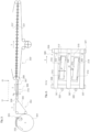
- the Figure 3 now shows a schematic representation of a floor laying device according to the invention.
- the floor laying device 300 initially comprises a separating device, which is illustrated here using the example of a so-called rotary feeder 301, with which a piece of hose 302 is removed from the stack of hose pieces 303.
- the piece of hose is peeled off from the underside of the stack of hose pieces.
- the function of such a rotary feeder is described in the publication, for example DE 32 14 342 A1 shown and explained.
- the isolated piece of hose is then handed over to a transfer conveyor 304.
- This can, for example, comprise several, in particular two, transport belts 305 that run parallel and are spaced apart in the direction of the tube's longitudinal axis and can be driven by at least one drive.
- transport speed can be varied independently of the transport speed of the floor layer, so that an alignment in the longitudinal direction can be carried out. If parallel transport belts are driven separately, they can also be driven at a differential speed so that alignment in the direction of rotation can be carried out.
- the transfer conveyor 304 is followed by an alignment device 306, which is in the Figure 4 is also shown in the top view.
- This alignment device is similar to the alignment device 201 from the Figure 2 constructed
- This alignment device 306 comprises several parallel transport elements, which can be designed as belts 307. These transport elements can contain a common drive component, here a shaft 308, with which the transport elements can be driven. Another shaft 309 can be used to deflect the belts 307.
- the piece of hose 302, not shown, can be transported on these transport elements.
- an alignment unit 310 is arranged within this transport device.
- This includes several conveying elements, which can be designed as transport belts 311, 312, which can be driven independently of one another.
- the transport belt 311 rotates endlessly on two shafts 313, 313 ', at least one of which can be driven by a drive, not shown.
- the transport belt 312 runs endlessly on the shafts 314, 314', with at least one of the shafts being drivable. All waves are stored in a frame 315. This frame can be adjusted in height direction H (represented by a double arrow in the Figure 3 ) can be moved.
- the frame is displaceable so that the transport belts 311 can protrude upwards beyond the transport elements 307. This means that the hose pieces 302 only pass through transported by the transport belts.
- the alignment unit 310 When the alignment unit 310 has completed an alignment (ie the actual position corresponds to the target position within tolerance limits), the frame can be lowered again and the piece of hose is transported further at machine speed.
- the frame To enable the rotational alignment ⁇ R, it is intended to mount the frame so that it can rotate about a vertical axis, which is indicated by the double arrow D.
- the frame can be mounted on a turntable, with a rotary drive (not shown) being provided to apply a rotational force to the frame 310.
- a rotary drive (not shown) being provided to apply a rotational force to the frame 310.
- the transport belts 311 and 312 are operated at different speeds. This means that a rotation cannot be caused or not only by a rotation of the frame 310, but also by a twisting of the hose piece on the transport belts 311, 312.
- the alignment device can, as already stated in the Figure 2 is shown, also include a limit 321, which limits the alignment movement in the transverse direction, and / or cams 322, which limit the longitudinal alignment.
- At least one sensor 320 can be arranged in or on the alignment device 306 in order to be able to determine the actual position of the hose piece.
- further sensors can be provided for the same purpose within the entire floor laying device.
- a sensor can be a light barrier, a light button, but also a camera.
- a sensor includes every optoelectronic component understand that the edges of the piece of hose are optically detected and the detection of an edge is electronically forwarded to a computing and control device.
- This computing and control device which is not shown in the figures, can now determine the actual position of the hose piece relative to the floor laying device from the sensor signals and compare it with the target position. From the deviations determined, the computing and control device now generates control signals for the drives described above.
- the Figure 3 now shows a transport system 330, which includes main transport belts 331 and 331 ', between which the hose pieces 302 are held clamped so that the latter do not move relative to the main transport belts.
- the functional components necessary for forming floors such as creasing devices, floor opening devices, gluing devices, cover sheet application devices and feeding devices, are arranged along the transport system.
- further functional components can be provided, such as an internal locking device.
- Reference symbol list 101 Piece of hose 102 First open ending 103 Second open ending 104 vertical axis 201 Alignment device 202 Transport facility 203 Conveyor belt 204 cam 205 Limitation 206 belt 210 sensor 211 Data line 212 Control unit 213 Data line 300 Floor laying equipment 301 Rotary feeder 302 Piece of hose 303 Stack of hose pieces 304 Transfer conveyor 305 Transport belt 306 Alignment device 307 belt 308 Wave 309 Wave 310 Alignment device 311 Transport belt 312 Transport belt 313 Wave 313' 314 Wave 314 ⁇ 315 Frame 320 sensor 321 Limitation 322 cam 330 Transportation system 331 Main transport belt 331' S Longitudinal axis T Transport direction H Altitude direction
Description
Die Erfindung betrifft eine Bodenlegeeinrichtung nach dem Oberbegriff des Patentanspruchs 1 sowie ein Verfahren nach dem Oberbegriff des Patentanspruchs 5.The invention relates to a floor laying device according to the preamble of patent claim 1 and a method according to the preamble of patent claim 5.
Zum Anformen von Böden an ein Schlauchstück in einer Bodenlegeeinrichtung ist es notwendig, das Schlauchstück zunächst auszurichten, bevor verschiedene Werkzeuge an das Schlauchstück zwecks Anformung von Böden angreifen. Die Schlauchstücke sind dabei mit ihrer Schlauchlängsachse quer zur Transportrichtung angeordnet. Dazu wird in bekannten, gattungsgemäßen Vorrichtungen zur einzelnen Ausrichtung der Schlauchstücke, die vorzugsweise aus Papier bestehen, ein Schlauchausrichtetisch eingesetzt. Das in einer Schlauchstückvereinzelungseinrichtung von einem Schlauchstückstapel vereinzelte Schlauchstück wird auf eine Ausrichteeinheit, mit welcher die Schlauchstücke ausrichtbar sind, ausgetragen. Eine solche Ausrichteeinheit umfasst eine Transporteinrichtung, mit welcher das Schlauchstück in einer Transportrichtung mit einer Transportgeschwindigkeit transportierbar ist, beispielsweise mit einer Mehrzahl parallel und in Transportrichtung laufender Bänder. Aus dem Stand der Technik ist es zudem bekannt, dass die Bänder die auf der Transportseite befestigten Anschläge aufweisen. Die Anschläge sind im Abstand des Maschinentaktes angeordnet. Im Raum zwischen den Bändern ist jeweils wenigstens ein Förderelement angeordnet, welches als Riemen ausgestaltet sein kann und welches unter einem Neigungswinkel schräg zur Transportrichtung steht. Diese Förderelemente haben in der Regel eine gegenüber der Transportgeschwindigkeit erhöhte Geschwindigkeit, so dass eine Differenzgeschwindigkeit zur Transportgeschwindigkeit erzeugt wird.To form floors onto a piece of hose in a floor laying device, it is necessary to first align the piece of hose before various tools attack the piece of hose to form floors. The hose pieces are arranged with their longitudinal hose axis transverse to the transport direction. For this purpose, a tube alignment table is used in known, generic devices for the individual alignment of the tube pieces, which are preferably made of paper. The piece of hose separated from a stack of hose pieces in a hose piece separating device is discharged to an alignment unit with which the hose pieces can be aligned. Such an alignment unit comprises a transport device with which the piece of hose can be transported in a transport direction at a transport speed, for example with a plurality of belts running parallel and in the transport direction. It is also known from the prior art that the belts have stops attached to the transport side. The stops are arranged at a distance of the machine cycle. At least one conveying element is arranged in the space between the belts, which can be designed as a belt and which is at an angle of inclination obliquely to the transport direction. These conveyor elements usually have one Speed increased compared to the transport speed, so that a difference speed to the transport speed is generated.
Da in der Regel die Förderelemente und die Transporteinrichtung von einem gemeinsamen Antrieb angetrieben werden, hat die Differenzgeschwindigkeit eine lineare Abhängigkeit von der Transportgeschwindigkeit. Dies betrifft sowohl die Längs- als auch die Querrichtung, bezogen auf das Schlauchstück. Ferner ist in der Regel ein einseitig und vertikal angeordnetes Transportband vorgesehen, welches die Begrenzung der seitlichen Positionen der Schlauchstücke übernimmt. Verallgemeinert kann gesagt werden, dass mittels der Förderelemente das Schlauchstück relativ zur Transporteinrichtung verschiebbar ist. Auf diese Weise wird das Schlauchstück ausgerichtet.Since the conveying elements and the transport device are usually driven by a common drive, the differential speed has a linear dependence on the transport speed. This applies to both the longitudinal and transverse directions, based on the piece of hose. Furthermore, a one-sided and vertically arranged conveyor belt is generally provided, which limits the lateral positions of the hose pieces. In general, it can be said that the piece of hose can be moved relative to the transport device by means of the conveying elements. In this way the piece of hose is aligned.
Daher wird das mit Taktgeschwindigkeit auf der Ausrichteeinrichtung aufgelegte Werkstück nun von den schräg angeordneten, in der Regel schneller laufenden Förderelementen über die entstehende Gleitreibung zwischen Bändern und Werkstück zu den vorderen Anschlägen gefördert, bis das Schlauchstück an diesen Anschlägen anliegt. Da die Anschläge auch in Querrichtung voneinander beabstandet sind, erfolgt dabei auch bei Bedarf eine Drehung des Schlauchstücks um eine Achse, die senkrecht zur Schlauchebene steht. Dabei wird, wenn das Schlauchstück bereits an einem Anschlag anliegt, dieses um diesen Anschlagpunkt gedreht, bis es auch an einem weiteren Anschlag anliegt. Zudem erfolgt gleichzeitig eine Querausrichtung, das bedeutet, dass das Schlauchstück auch gegen den seitlichen Anschlag läuft. Mit anderen Worten erfolgt auf der Ausrichteinheit die Durchführung von Ausrichtungen des Schlauchstücks
- quer zur Transportrichtung
- in Transportrichtung und/oder
- um eine Drehachse, welche senkrecht zur Schlauchebene steht.
- transverse to the transport direction
- in the transport direction and/or
- around an axis of rotation that is perpendicular to the hose plane.
Im Rahmen der vorliegenden Erfindung ist mit einer Ausrichtung um eine Drehachse gemeint, dass eine Drehung mit einem Drehwinkel von weniger als 20 Grad, insbesondere weniger als 10 Grad und vorzugsweise weniger als 5 Grad erfolgt.In the context of the present invention, an alignment about an axis of rotation means that a rotation takes place with a rotation angle of less than 20 degrees, in particular less than 10 degrees and preferably less than 5 degrees.
Je nach Reibwert des Schlauchstücks erreicht dieses die Ausrichtanschläge früher oder später. Auch das seitliche Ausrichtband wird teilweise früh erreicht. Somit kommt es vor, dass der Ausrichtvorgang bereits zufriedenstellend abgeschlossen ist, aber das Schlauchstück noch nicht am Ende einer Ausrichtstrecke angekommen ist. Da auch danach noch die schräg verlaufenden Förderelemente auf das Schlauchstück wirken, wird dieses weiterhin gegen die Anschläge gedrückt. Dabei kann es passieren, dass die Schlauchstücke beschädigt werden, insbesondere wenn sie aus sehr flexiblem Material bestehen.Depending on the friction value of the piece of hose, it reaches the alignment stops sooner or later. The lateral alignment band is also reached early in some cases. It therefore happens that the alignment process has already been completed satisfactorily, but the piece of hose has not yet reached the end of an alignment section. Since the inclined conveying elements continue to act on the piece of hose, it continues to be pressed against the stops. It can happen that the pieces of hose are damaged, especially if they are made of very flexible material.
Die Aufgabe der vorliegenden Erfindung ist es daher, eine Bodenlegeeinrichtung zur Herstellung von mit zumindest einem Boden versehenen Schlauchstücken zu schaffen, die Beschädigungen von Schlauchstücken bei deren Ausrichtung weitgehend vermeidet.The object of the present invention is therefore to create a floor laying device for producing hose pieces provided with at least one bottom, which largely avoids damage to hose pieces during their alignment.
Erfindungsgemäß wird diese Aufgabe durch sämtliche Merkmale des Anspruchs 1 gelöst. In den abhängigen Ansprüchen sind mögliche Ausgestaltungen der Erfindung angegeben.According to the invention, this object is achieved by all the features of claim 1. Possible embodiments of the invention are specified in the dependent claims.
Gemäß der vorliegenden Erfindung ist vorgesehen, dass die Differenzgeschwindigkeit und/oder die relative Lage der Förderelemente zur Transporteinrichtung veränderbar, insbesondere steuerbar, sind.According to the present invention it is provided that the differential speed and/or the relative position of the conveying elements to the transport device can be changed, in particular controllable.
Auf diese Weise kann der Ausrichtvorgang so beeinflusst werden, dass beispielsweise die Durchführung der Ausrichtungen im Wesentlichen dann beendet wird, wenn das Schlauchstück das Ende der Ausrichtstrecke erreicht. Dies kann am einfachsten dadurch erfolgen, dass die Differenzgeschwindigkeit veränderbar oder gar steuerbar ist. Damit kann die Zeitdauer des Ausrichtvorganges beeinflusst werden, so dass am Ende der Ausrichtstrecke die Belastung für das Material möglichst gering gewesen ist. Um das zu erreichen kann vorgesehen sein, dass die Förderelemente mit einem eigenen Antrieb antreibbar sind oder dass eine variabel einstellbare Getriebestufe zwischen Hauptantrieb und Förderelementen vorgesehen ist. Insbesondere bei mit einem Neigungswinkel angeordneten Förderelementen kann dennoch trotz der bereits beendeten Ausrichtungen noch eine Kraft auf das Schlauchelement wirken.In this way, the alignment process can be influenced in such a way that, for example, the implementation of the alignments is essentially ended when the piece of hose reaches the end of the alignment section. The easiest way to do this is to change or even control the differential speed. This allows the duration of the alignment process to be influenced so that at the end of the alignment section the load on the material is as low as possible. In order to achieve this, it can be provided that the conveying elements can be driven with their own drive or that a variably adjustable gear stage is provided between the main drive and the conveying elements. Particularly when conveying elements are arranged at an angle of inclination, despite this, The already completed alignments still have a force acting on the hose element.
Daher kann es alternativ oder zusätzlich vorgesehen sein, dass die relative Lage der Förderelemente zur Transportrichtung veränderbar, insbesondere steuerbar ist. Damit kann insbesondere gemeint sein, dass die Förderelemente vertikal, in Querrichtung und/oder hinsichtlich des Neigungswinkels relativ zur Transporteinrichtung anpassbar sind, wobei das Schlauchstück horizontal und in einer Richtung, die im Wesentlichen senkrecht zur seiner Schlauchlängsachse liegt, transportiert wird. Bei einer Veränderbarkeit der vertikalen Lage können die Förderelemente in eine Position unterhalb der Transporteinrichtung bringbar sein, so dass die Förderelemente außer Kontakt mit dem Schlauchstück treten und das Schlauchstück nicht weiter relativ zur Transporteinrichtung bewegbar ist. Es ist ferner denkbar, dass die gesamten Förderelemente relativ zur Transporteinrichtung verschiebbar und/oder hinsichtlich des Neigungswinkels veränderbar sind. In diesem Fall können beispielsweise die Querausrichtung und/oder die Drehausrichtung durch unabhängige Bewegungen der Förderelemente durchgeführt werden. Die Unabhängigkeit der Bewegungen lässt entsprechend zu, dass die Ausrichtungen quer zur Transportrichtung und/oder um die Drehachse unabhängig von der Ausrichtstrecke sein können, so dass der Startzeitpunkt und der Endzeitpunkt der Ausrichtungen unabhängig wählbar sind.Therefore, it can alternatively or additionally be provided that the relative position of the conveying elements to the transport direction can be changed, in particular controllable. This can mean, in particular, that the conveying elements can be adjusted vertically, in the transverse direction and/or with regard to the angle of inclination relative to the transport device, with the piece of hose being transported horizontally and in a direction that is essentially perpendicular to its longitudinal axis. If the vertical position can be changed, the conveying elements can be brought into a position below the transport device, so that the conveying elements come out of contact with the hose piece and the hose piece can no longer be moved relative to the transport device. It is also conceivable that the entire conveying elements are displaceable relative to the transport device and/or can be changed with regard to the angle of inclination. In this case, for example, the transverse alignment and/or the rotational alignment can be carried out by independent movements of the conveying elements. The independence of the movements accordingly allows the alignments transverse to the transport direction and/or around the axis of rotation to be independent of the alignment distance, so that the start time and the end time of the alignments can be selected independently.
Mit den vorgenannten Ausführungsformen ist es somit möglich, Beschädigungen von Schlauchstücken während des Ausrichtens zu reduzieren oder sogar gänzlich zu eliminieren, da die auf die Schlauchstücke wirkenden Ausrichtkräfte durch die Erfindung so weit wie möglich auf das erforderliche Maß reduzierbar sind.With the aforementioned embodiments, it is therefore possible to reduce or even completely eliminate damage to pieces of hose during alignment, since the alignment forces acting on the pieces of hose can be reduced as much as possible to the required level by the invention.
Gemäß der Erfindung ist eine Rechen- und Steuereinrichtung vorgesehen, welcher Informationen zur Ist-Position des Schlauchstücks relativ zur Transporteinrichtung zur Verfügung stellbar sind und welcher die Soll-Positionen des Schlauchstücks relativ zur Transporteinrichtung bekannt sind, wobei bei Abweichungen der Ist-Position zur Soll-Position des Schlauchstücks mit der Rechen- und Steuereinrichtung Steuerbefehle für die Änderung der Differenzgeschwindigkeit und/oder der relativen Lage der Förderelemente generierbar sind. Mit anderen Worten wird für eine beschädigungsreduzierte Ausrichtung zunächst die Ist-Position eines jeden Schlauchstücks erfasst und dieser dann, vorzugsweise individuell, ausgerichtet, indem passend die Förderelemente angesteuert und/oder hinsichtlich ihrer Position verändert werden, wie es bereits weiter oben beschrieben wurde. Nach der Erfassung der Ist-Position kann mittels der Rechen- und Steuereinrichtung die Größe der Abweichungen zur Soll-Position ermittelt werden. Nach der Ermittlung der Abweichungen generiert die Steuer- und Rechenvorrichtung Steuerbefehle, die an die Förderelemente und/oder deren Antrieb bzw. Stelltriebe geleitet werden. Dies kann als Steuerung der Ausrichtung verstanden werden, wobei Generierung der Steuerbefehle und die Ansteuerung der Förderelemente derart erfolgt, dass das Schlauchstück im Anschluss die Soll-Position innerhalb von Toleranzgrenzen eingenommen hat.According to the invention, a computing and control device is provided to which information on the actual position of the piece of hose relative to the transport device can be made available and to which the target positions of the piece of hose relative to the transport device are known, whereby in the event of deviations from the actual position to the target Position of the Hose piece with the computing and control device control commands for changing the differential speed and / or the relative position of the conveying elements can be generated. In other words, for a damage-reduced alignment, the actual position of each piece of hose is first recorded and this is then aligned, preferably individually, by appropriately controlling the conveying elements and/or changing their position, as already described above. After the actual position has been recorded, the size of the deviations from the target position can be determined using the computing and control device. After determining the deviations, the control and computing device generates control commands that are sent to the conveying elements and/or their drives or actuators. This can be understood as controlling the alignment, whereby the control commands are generated and the conveying elements are activated in such a way that the piece of hose then assumes the desired position within tolerance limits.
Weiterhin ist es vorteilhaft, wenn mit einer Rechen- und Steuereinrichtung ein Zeitpunkt berechenbar ist, zu dem die Differenzgeschwindigkeit auf oder kleiner Null reduzierbar ist und/oder die relative Lage der Förderelemente zur Transporteinrichtung derart veränderbar ist, dass das Schlauchstück relativ zur Transporteinrichtung ruht. Damit kann die Einwirkung der Förderelemente auf das Schlauchstück beendet werden, wenn das Schlauchstück die Soll-Position innerhalb von Toleranzgrenzen erreicht haben müsste. Es wird also insbesondere das Erreichen der Soll-Lage nicht verifiziert, sondern lediglich vorausberechnet. Der Aufbau einer vollständigen Regelschleife ist damit nicht notwendig.Furthermore, it is advantageous if a computing and control device can be used to calculate a time at which the differential speed can be reduced to or less than zero and/or the relative position of the conveying elements to the transport device can be changed in such a way that the piece of hose rests relative to the transport device. This means that the action of the conveying elements on the piece of hose can be ended when the piece of hose should have reached the desired position within tolerance limits. In particular, the achievement of the target position is not verified, but merely calculated in advance. It is therefore not necessary to set up a complete control loop.
Ferner ist es vorteilhaft, wenn die Bodenlegeeinrichtung wenigstens einen Sensor umfasst, mit welchem die Ist-Position des Schlauchstücks relativ zur Transporteinrichtung erfassbar ist. Ein Sensor kann dabei ein Lichttaster, eine Lichtschranke, eine Kamera oder ein beliebiges anderes optoelektronisches Bauteil sein, das beispielsweise eine Kontraständerung in ein elektrisches Signal umsetzt und dieses einer Rechen- und Steuereinrichtung zugänglich macht. Insbesondere eine Kamera kann vorteilhaft sein, da mit ihr ein Bild des kompletten Schlauchstücks aufzeichenbar und die Ist-Lage des Schlauchstücks einfach ermittelbar ist.Furthermore, it is advantageous if the floor laying device comprises at least one sensor with which the actual position of the hose piece relative to the transport device can be detected. A sensor can be a light button, a light barrier, a camera or any other optoelectronic component that, for example, converts a change in contrast into an electrical signal and makes this accessible to a computing and control device. A camera in particular can be advantageous because it can take a picture of the... entire hose section can be recorded and the actual position of the hose section can be easily determined.
Vorteilhaft ist es außerdem, wenigstens einen zweiten Sensor vorzusehen, mit welchem die Ist-Position des Schlauchstücks relativ zur Transporteinrichtung erfassbar ist zu einem Zeitpunkt, der nach dem Zeitpunkt liegt, an dem mit einem ersten Sensor die Ist-Position des Schlauchstücks relativ zur Transporteinrichtung erfassbar ist. Damit kann die aktuelle Ist-Position, beispielsweise während der Durchführung der Ausrichtung, nochmals geprüft werden und die Steuerbefehle nochmals angepasst werden. Eine Prüfung der Ist-Position kann auch nach der erfolgten Ausrichtung erfolgen, um Ausrichtfehler erkennen und notfalls das Schlauchstück ausschleusen zu können. Damit kann ein intaktes Schlauchstück nochmals der Bodenlegeeinrichtung zugeführt werden, und es wird ein fehlerhaftes Anformen eines Bodens, das zu Ausschuss führen würde, vermieden.It is also advantageous to provide at least one second sensor with which the actual position of the hose piece relative to the transport device can be detected at a time that is after the time at which the actual position of the hose piece relative to the transport device can be detected with a first sensor is. This means that the current actual position can be checked again, for example while the alignment is being carried out, and the control commands can be adjusted again. The actual position can also be checked after alignment has been completed in order to detect alignment errors and, if necessary, to be able to reject the piece of hose. This means that an intact piece of hose can be fed to the floor laying device again, and incorrect formation of a floor, which would lead to waste, is avoided.
Die oben genannte Aufgabe wird auch gelöst durch ein Verfahren gemäß Anspruch 5.The above-mentioned task is also solved by a method according to claim 5.
Damit werden die gleichen Vorteile erzielt, wie sie bereits im Zusammenhang mit einer erfindungsgemäßen Bodenlegeeinrichtung beschrieben worden sind.This achieves the same advantages as have already been described in connection with a floor laying device according to the invention.
Weitere Vorteile, Merkmale und Einzelheiten der Erfindung gehen aus der nachfolgenden Beschreibung hervor, in der unter Bezugnahme auf die Figuren verschiedene Ausführungsbeispiele im Einzelnen erläutert sind. Dabei können die in den Ansprüchen und in der Beschreibung erwähnten Merkmale jeweils einzeln für sich oder beliebige Kombinationen erwähnter Merkmale erfindungswesentlich sein. Im Rahmen der gesamten Offenbarung gelten Merkmale und Einzelheiten, die im Zusammenhang mit dem erfindungsgemäßen Verfahren beschrieben sind, selbstverständlich auch im Zusammenhang mit der erfindungsgemäßen Bodenlegeeinrichtung und jeweils umgekehrt, so dass bezüglich der Offenbarung zu den einzelnen Aspekten der Erfindung stets wechselseitig Bezug genommen wird beziehungsweise werden kann. Die einzelnen Figuren zeigen:
- Fig. 1
- Eine perspektivische Ansicht eines Schlauchstücks sowie der durchführbaren Ausrichtrichtungen
- Fig. 2
- Eine erste Ausführungsform einer Ausrichteinheit als Komponente der Erfindung
- Fig. 3
- Seitenansicht einer erfindungsgemäßen Bodenlegeeinrichtung
- Fig. 4
- Eine zweite Ausführungsform einer Ausrichteinheit als Komponente der Erfindung
- Fig. 1
- A perspective view of a piece of tubing and the possible alignment directions
- Fig. 2
- A first embodiment of an alignment unit as a component of the invention
- Fig. 3
- Side view of a floor laying device according to the invention
- Fig. 4
- A second embodiment of an alignment unit as a component of the invention
Die
Die
Um nun ein Ausrichten durchführen zu können, sind Förderelemente vorgesehen, die in der vorliegenden Figur als Riemen 206 ausgestaltet sind, auf welchen das Schlauchstück aufliegt. Diese Riemen 206 laufen vorzugsweise auf gemeinsamen Rollen 207, von denen zumindest eine durch einen eigenen, von der übrigen Ausrichteinrichtung unabhängigen Antrieb antreibbar ist. Der Antrieb ist nicht dargestellt. Die Riemen 206 laufen mit einer Differenzgeschwindigkeit und mit einer höheren Absolutgeschwindigkeit als die Transportbänder 203, so dass ein Schlauchstück, das in Kontakt mit den Riemen 206 steht, an die Nocken 204 geschoben wird. Voraussetzung für diese Funktionsweise ist, dass die Haftreibung zwischen den Förderelementen, hier also die Riemen 206, und Schlauchstück größer ist als die Gleitreibung zwischen Transporteinrichtung und Schlauchstück. Nur dann ist ein Verschieben des Schlauchstücks relativ zur Transporteinrichtung und damit eine Ausrichtung möglich.In order to be able to carry out alignment, conveying elements are provided, which in the present figure are designed as
Ferner sind die Riemen 206 in einem Winkel α relativ zur Transportrichtung T angeordnet, so dass ein Schlauchstück zusätzlich gegen die Begrenzung 205 geschoben wird.Furthermore, the
In Transportrichtung der Förderelemente vorgeordnet sind ein oder mehrere Sensoren 210, die die aktuelle Position eines Schlauchstücks detektieren und über die Datenleitung 211 Positionsinformationen an die Rechen- und Steuereinheit 212 weiterleiten. Die Rechen- und Steuereinheit ist dazu vorgesehen und eingerichtet, diese Positionsinformation, also die Ist-Position, eines Schlauchstücks mit der Soll-Position zu vergleichen und bei Abweichungen Steuerbefehle zu generieren. Diese Steuerbefehle können im vorliegenden Ausführungsbeispiel der
Die
Dem Übergabeförderer 304 schließt sich im gezeigten Ausführungsbeispiel eine Ausrichteinrichtung 306 an, die in der
Innerhalb dieser Transporteinrichtung ist im gezeigten Ausführungsbeispiel eine Ausrichteinheit 310 angeordnet. Diese umfasst mehrere Förderelemente, die als Transportriemen 311, 312 ausgestaltet sein können, welche unabhängig voneinander antreibbar sein können. Dazu ist der Transportriemen 311 auf zwei Wellen 313, 313' endlos umlaufend, von denen wenigstens eine durch einen nicht gezeigten Antrieb antreibbar ist. Auf gleiche Weise ist der Transportriemen 312 auf den Wellen 314, 314' endlos umlaufend, wobei wenigstens eine der Wellen antreibbar ist. Alle Wellen sind in einem Rahmen 315 gelagert. Dieser Rahmen kann in Höhenrichtung H (dargestellt durch einen Doppelpfeil in der
Um nun eine Querausrichtung zu ermöglichen, ist vorgesehen, dass der Rahmen 315 quer zur Transportrichtung T verschiebbar ist, was durch den Doppelpfeil P angedeutet ist. Hierzu ist eine nicht gezeigte Verschiebeeinrichtung vorgesehen. Im gezeigten Ausführungsbeispiel wäre also der Rahmen parallel zu den Wellen 308 und 309 verschiebbar. Alternativ kann die Verschieberichtung auch parallel zu einer der Wellen 313, 313', 314, 314' liegen.In order to enable transverse alignment, it is provided that the
Zur Ermöglichung der Drehausrichtung ΔR ist vorgesehen, den Rahmen um eine Hochachse drehbar zu lagern, was durch den Doppelpfeil D angedeutet ist. Dazu kann der Rahmen auf einer Drehscheibe gelagert sein, wobei zur Beaufschlagung des Rahmens 310 mit einer Drehkraft ein nicht gezeigter Drehantrieb vorgesehen ist. Zusätzlich oder alternativ kann vorgesehen sein, die Transportriemen 311 und 312 mit voneinander verschiedenen Geschwindigkeiten zu betreiben. Damit kann eine Drehung nicht oder nicht nur durch eine Drehung des Rahmens 310, sondern auch durch ein Verdrehen des Schlauchstücks auf den Transportriemen 311, 312 hervorgerufen werden.To enable the rotational alignment ΔR, it is intended to mount the frame so that it can rotate about a vertical axis, which is indicated by the double arrow D. For this purpose, the frame can be mounted on a turntable, with a rotary drive (not shown) being provided to apply a rotational force to the
Die Ausrichteinrichtung kann, wie es bereits in der
Ferner kann in oder an der Ausrichteinrichtung 306 wenigstens ein Sensor 320 angeordnet sein, um die Ist-Lage des Schlauchstücks feststellen zu können. Alternativ oder zusätzlich können weitere Sensoren zum gleichen Zweck innerhalb der gesamten Bodenlegevorrichtung vorgesehen werden. Ein Sensor kann eine Lichtschranke, ein Lichttaster, aber auch eine Kamera sein. Grundsätzlich ist unter einem Sensor jedes optoelektronische Bauteil zu verstehen, dass optisch die Kanten des Schlauchstücks erfasst und auf elektronischem Weg das Detektieren einer Kante an einer Rechen- und Steuervorrichtung weiterleitet. Diese Rechen- und Steuervorrichtung, die in den Figuren nicht gezeigt ist, kann nun aus den Sensorsignalen die Ist-Lage des Schlauchstücks relativ zur Bodenlegeeinrichtung ermitteln und mit der Soll-Lage vergleichen. Aus den ermittelten Abweichungen generiert die Rechen- und Steuervorrichtung nun Steuersignale für die oben beschriebenen Antriebe.Furthermore, at least one
Die
Es wird an dieser Stelle nochmals wiederholt, dass verschiedene Merkmale der vorstehend beschriebenen Ausführungsformen, insbesondere die der Ausführungsbeispiele der
Claims (5)
- A bottom-forming device (300) for producing pieces of tubing (302) provided with at least one bottom, comprising an aligning device (201, 306) for carrying out alignments of the piece of tubing- transverse to the transport direction (T)- in the transport direction and/or- about an axis of rotation (H), which is perpendicular to the tubing plane,wherein the aligning device• comprises a transport device (202, 307), with which the piece of tubing can be transported in a transport direction at a transport speed,• comprises conveying elements (206, 311, 312), with which the piece of tubing can be acted upon such that the piece of tubing can be moved relative to the transport direction, wherein the conveying elements can be operated with a differential speed to the transport speed, wherein the differential speed and/or the relative position of the conveying elements to the transport device can be changed, in particular can be controlled,characterized in that
a computing and control device (212) is provided, to which information regarding the actual position of the piece of tubing relative to the transport device can be made available and to which the desired positions of the piece of tubing relative to the transport device are known, wherein in the event of deviations of the actual position from the desired position of the piece of tubing, control commands for changing the differential speed and/or the relative position of the conveying elements can be generated with the computing and control device. - The bottom-forming device according to the preceding claim,
characterized in that
with a computing and control device (212), a point in time can be calculated, at which the differential speed can be reduced to zero and/or the relative position of the conveying elements (206, 311, 312) to the transport direction (202, 307) can be changed in such a way that the piece of tubing (302) rests relative to the transport device. - The bottom-forming device according to the any one of the preceding claims,
characterized in that
it comprises at least one first sensor (210, 320), with which the actual position of the piece of tubing (302) relative to the transport device (202, 307) can be detected. - The bottom-forming device according to any one of the preceding claims,
characterized in that
at least one second sensor is provided, with which the actual position of the piece of tubing (302) relative to the transport device (202, 307) can be detected at a point in time, which is after the point in time at which the position of the piece of tubing relative to the transport device can be detected with a first sensor (210, 320). - A method for producing pieces of tubing (302) provided with at least one bottom, in which alignments of the piece of tubing are carried out with an aligning device (201, 306)- transverse to the transport direction (T)- in the transport direction and/or- about an axis of rotation (H), which is perpendicular to the tubing plane, wherein• with a transport device (202, 307) of the aligning device the piece of tubing is transported in a transport direction at a transport speed• with conveying elements (206, 311, 312) the piece of tubing is acted upon, so that the piece of tubing is displaced relative to the transport device, wherein the conveying elements are operated at a differential speed to the transport speed,wherein the differential speed and/or the relative position of the conveying elements to the transport device is changed, in particular is controlled,characterized in thatwith a computing and control device (212) information is made available on the actual position of the piece of tubing relative to the transport device and to which the desired positions of the piece of tubing relative to the transport device are made known, wherein in the event of deviations of the actual position from the desired position of the piece of tubing control commands for changing the differential speed and/or the relative position of the conveying elements are generated with the computing and control device.
Applications Claiming Priority (2)
| Application Number | Priority Date | Filing Date | Title |
|---|---|---|---|
| DE102018210563 | 2018-06-28 | ||
| PCT/EP2019/067403 WO2020002637A1 (en) | 2018-06-28 | 2019-06-28 | Bottom-forming device and method for producing pieces of tubing provided with at least with one bottom |
Publications (2)
| Publication Number | Publication Date |
|---|---|
| EP3814256A1 EP3814256A1 (en) | 2021-05-05 |
| EP3814256B1 true EP3814256B1 (en) | 2024-01-10 |
Family
ID=67145790
Family Applications (1)
| Application Number | Title | Priority Date | Filing Date |
|---|---|---|---|
| EP19735533.2A Active EP3814256B1 (en) | 2018-06-28 | 2019-06-28 | Bottom-forming device and method for producing pieces of tubing provided with at least with one bottom |
Country Status (2)
| Country | Link |
|---|---|
| EP (1) | EP3814256B1 (en) |
| WO (1) | WO2020002637A1 (en) |
Family Cites Families (6)
| Publication number | Priority date | Publication date | Assignee | Title |
|---|---|---|---|---|
| DE3214342C2 (en) | 1982-04-19 | 1985-06-13 | Windmöller & Hölscher, 4540 Lengerich | Device for supplying suction air to a rotary feeder |
| GB9717938D0 (en) * | 1997-08-22 | 1997-10-29 | De La Rue Thomas & Co Ltd | Document alignment system |
| DE19853026C1 (en) * | 1998-11-18 | 2000-03-30 | Icoma Fbs Gmbh Packtechnik | Device for aligning sections of tubing e.g. multiple layers of paper cut in grades on their face side, has first conveyor belts running parallel to each other set up at a preset distance from second conveyor belts |
| EP2277812B1 (en) * | 2009-07-21 | 2013-07-03 | Müller Martini Holding AG | Method for lateral alignment of products with level base, in particular printed products and transport device for carrying out the method |
| DE102010049057A1 (en) * | 2010-10-20 | 2012-04-26 | Heidelberger Druckmaschinen Ag | Sheet folding machine and method for operating a folding machine |
| DE102011003381A1 (en) * | 2011-01-31 | 2012-08-02 | Windmöller & Hölscher Kg | Method and system for processing orders for the production of bags |
-
2019
- 2019-06-28 EP EP19735533.2A patent/EP3814256B1/en active Active
- 2019-06-28 WO PCT/EP2019/067403 patent/WO2020002637A1/en active Application Filing
Also Published As
| Publication number | Publication date |
|---|---|
| EP3814256A1 (en) | 2021-05-05 |
| WO2020002637A1 (en) | 2020-01-02 |
Similar Documents
| Publication | Publication Date | Title |
|---|---|---|
| EP0947455A1 (en) | Method and device for feeding flat articles positionally accurate to a process station | |
| DE102007036020A1 (en) | Aligning food products | |
| EP1270473A2 (en) | Skew compensation device for corrugated board machine | |
| DE202016008856U1 (en) | Thermoforming packaging machine | |
| EP1892086B1 (en) | Position regulation for a bottomer with image processing | |
| EP2810904A1 (en) | Feeding of loose stacks of sheets into a transport channel | |
| EP3868694A1 (en) | Rotary device for a sanitary product manufacturing system | |
| EP3694799B1 (en) | Sheet orientation device, machine for processing a sheet, and method for orienting a sheet | |
| EP3896018B1 (en) | Method and device for positionally accurate feeding of sheet metal plates to a machining process or a machining unit | |
| EP2323492A1 (en) | Apparatus and method for automatically supplying fish to a fish processing machine | |
| DE8524540U1 (en) | Glass board washing machine | |
| DE19713106B4 (en) | Method and device for feeding workpieces | |
| EP3814256B1 (en) | Bottom-forming device and method for producing pieces of tubing provided with at least with one bottom | |
| EP3354121A1 (en) | Method for sensing workpieces, and sensing device | |
| DE102018222767A1 (en) | Transport device for containers and method for transporting containers | |
| DE102007027945A1 (en) | Method and device for producing a folded sheet | |
| DE102021134478A1 (en) | Dough processing apparatus and method | |
| CH690171A5 (en) | Apparatus for converting conveyor parts. | |
| DE102005045583A1 (en) | Method for separating stacked, disk-shaped elements and separating device | |
| DE202006002982U1 (en) | Laminating machine with a glueing and aligning section and a laminating section, in which the aligner has a set of feed rollers with a stop rail which can be moved across the rollers and angled to align the sheets | |
| WO2020002638A1 (en) | Bottom-forming device and method for producing pieces of tubing provided with at least one bottom | |
| EP1488916B1 (en) | Device for applying bag bottoms | |
| EP2392213B1 (en) | Supply device for dough pieces, in particular for pre-formed dough strings used in the production of pretzels and method for supplying dough pieces | |
| DE102022105608B3 (en) | Device for separating and removing individual parts and calibration method | |
| EP3702157B1 (en) | Method and device for accurately laying sheets |
Legal Events
| Date | Code | Title | Description |
|---|---|---|---|
| STAA | Information on the status of an ep patent application or granted ep patent |
Free format text: STATUS: UNKNOWN |
|
| STAA | Information on the status of an ep patent application or granted ep patent |
Free format text: STATUS: THE INTERNATIONAL PUBLICATION HAS BEEN MADE |
|
| STAA | Information on the status of an ep patent application or granted ep patent |
Free format text: STATUS: THE INTERNATIONAL PUBLICATION HAS BEEN MADE |
|
| PUAI | Public reference made under article 153(3) epc to a published international application that has entered the european phase |
Free format text: ORIGINAL CODE: 0009012 |
|
| STAA | Information on the status of an ep patent application or granted ep patent |
Free format text: STATUS: REQUEST FOR EXAMINATION WAS MADE |
|
| 17P | Request for examination filed |
Effective date: 20210128 |
|
| AK | Designated contracting states |
Kind code of ref document: A1 Designated state(s): AL AT BE BG CH CY CZ DE DK EE ES FI FR GB GR HR HU IE IS IT LI LT LU LV MC MK MT NL NO PL PT RO RS SE SI SK SM TR |
|
| DAV | Request for validation of the european patent (deleted) | ||
| DAX | Request for extension of the european patent (deleted) | ||
| GRAP | Despatch of communication of intention to grant a patent |
Free format text: ORIGINAL CODE: EPIDOSNIGR1 |
|
| STAA | Information on the status of an ep patent application or granted ep patent |
Free format text: STATUS: GRANT OF PATENT IS INTENDED |
|
| RIC1 | Information provided on ipc code assigned before grant |
Ipc: B31B 70/04 20170101ALI20230831BHEP Ipc: B65H 9/06 20060101ALI20230831BHEP Ipc: B31B 70/00 20170101ALI20230831BHEP Ipc: B65H 9/16 20060101ALI20230831BHEP Ipc: B65H 9/00 20060101ALI20230831BHEP Ipc: B65H 5/02 20060101AFI20230831BHEP |
|
| INTG | Intention to grant announced |
Effective date: 20230920 |
|
| GRAS | Grant fee paid |
Free format text: ORIGINAL CODE: EPIDOSNIGR3 |
|
| GRAA | (expected) grant |
Free format text: ORIGINAL CODE: 0009210 |
|
| STAA | Information on the status of an ep patent application or granted ep patent |
Free format text: STATUS: THE PATENT HAS BEEN GRANTED |
|
| AK | Designated contracting states |
Kind code of ref document: B1 Designated state(s): AL AT BE BG CH CY CZ DE DK EE ES FI FR GB GR HR HU IE IS IT LI LT LU LV MC MK MT NL NO PL PT RO RS SE SI SK SM TR |
|
| REG | Reference to a national code |
Ref country code: GB Ref legal event code: FG4D Free format text: NOT ENGLISH |
|
| REG | Reference to a national code |
Ref country code: CH Ref legal event code: EP |
|
| REG | Reference to a national code |
Ref country code: DE Ref legal event code: R096 Ref document number: 502019010355 Country of ref document: DE |
|
| REG | Reference to a national code |
Ref country code: IE Ref legal event code: FG4D Free format text: LANGUAGE OF EP DOCUMENT: GERMAN |