EP3813210B1 - Installationsvorrichtung für stromschienen sowie installationsverfahren - Google Patents
Installationsvorrichtung für stromschienen sowie installationsverfahren Download PDFInfo
- Publication number
- EP3813210B1 EP3813210B1 EP19205053.2A EP19205053A EP3813210B1 EP 3813210 B1 EP3813210 B1 EP 3813210B1 EP 19205053 A EP19205053 A EP 19205053A EP 3813210 B1 EP3813210 B1 EP 3813210B1
- Authority
- EP
- European Patent Office
- Prior art keywords
- devices
- traction
- busbar
- mounting
- installation device
- Prior art date
- Legal status (The legal status is an assumption and is not a legal conclusion. Google has not performed a legal analysis and makes no representation as to the accuracy of the status listed.)
- Active
Links
- 238000009434 installation Methods 0.000 title claims description 59
- 238000000034 method Methods 0.000 title claims description 12
- 230000000284 resting effect Effects 0.000 claims 1
- 239000004020 conductor Substances 0.000 description 39
- 239000000463 material Substances 0.000 description 5
- 238000010276 construction Methods 0.000 description 3
- 239000002184 metal Substances 0.000 description 3
- 230000005540 biological transmission Effects 0.000 description 2
- 230000000903 blocking effect Effects 0.000 description 2
- 238000011900 installation process Methods 0.000 description 2
- 230000010354 integration Effects 0.000 description 2
- MJIHNNLFOKEZEW-UHFFFAOYSA-N lansoprazole Chemical compound CC1=C(OCC(F)(F)F)C=CN=C1CS(=O)C1=NC2=CC=CC=C2N1 MJIHNNLFOKEZEW-UHFFFAOYSA-N 0.000 description 2
- 238000004519 manufacturing process Methods 0.000 description 2
- 238000005266 casting Methods 0.000 description 1
- 239000003795 chemical substances by application Substances 0.000 description 1
- 150000001875 compounds Chemical class 0.000 description 1
- 238000009826 distribution Methods 0.000 description 1
- 230000005611 electricity Effects 0.000 description 1
- 229920006333 epoxy cement Polymers 0.000 description 1
- 238000007373 indentation Methods 0.000 description 1
- 239000002986 polymer concrete Substances 0.000 description 1
- 229920005989 resin Polymers 0.000 description 1
- 239000011347 resin Substances 0.000 description 1
- 230000001360 synchronised effect Effects 0.000 description 1
- 238000005303 weighing Methods 0.000 description 1
- 238000004804 winding Methods 0.000 description 1
Images


Classifications
-
- H—ELECTRICITY
- H02—GENERATION; CONVERSION OR DISTRIBUTION OF ELECTRIC POWER
- H02G—INSTALLATION OF ELECTRIC CABLES OR LINES, OR OF COMBINED OPTICAL AND ELECTRIC CABLES OR LINES
- H02G3/00—Installations of electric cables or lines or protective tubing therefor in or on buildings, equivalent structures or vehicles
- H02G3/26—Installations of cables, lines, or separate protective tubing therefor directly on or in walls, ceilings, or floors
- H02G3/263—Installation, e.g. suspension, of conduit channels or other supports
-
- H—ELECTRICITY
- H02—GENERATION; CONVERSION OR DISTRIBUTION OF ELECTRIC POWER
- H02G—INSTALLATION OF ELECTRIC CABLES OR LINES, OR OF COMBINED OPTICAL AND ELECTRIC CABLES OR LINES
- H02G1/00—Methods or apparatus specially adapted for installing, maintaining, repairing or dismantling electric cables or lines
-
- H—ELECTRICITY
- H02—GENERATION; CONVERSION OR DISTRIBUTION OF ELECTRIC POWER
- H02G—INSTALLATION OF ELECTRIC CABLES OR LINES, OR OF COMBINED OPTICAL AND ELECTRIC CABLES OR LINES
- H02G5/00—Installations of bus-bars
Definitions
- the invention relates to an installation device for busbars and an installation method for installing busbars using this installation device.
- busbars are used as transmission lines between transformers, main and sub-distribution boards in factory buildings, commercial and administrative buildings, or as risers in high-rise buildings.
- Busbars and the installation devices provided for them are known e.g.
- Other mounting devices are known from the product catalog "LANZ the modern cable guide” from LANZ OENSINGEN AG from October 2015.
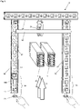
- the mounting device 9 shown and a lifting device 4 with two supporting devices 41A, 41B, which are used for the installation of busbars 1 in the ceiling 8 of a building.
- the mounting device 9 comprises a horizontal profile 91 mounted on the ceiling 8 and two designed as threaded rods Vertical profiles 92, between which the busbars 1 can be raised by means of the support devices 41A, 41B and associated traction cables 44A, 44B.
- a mounting profile 99 is used above the horizontal profile 91 to fasten the traction cables 44A, 44B.
- the traction cables 44A, 44B run via a first deflection roller 95, which is held at a first end of the mounting profile 99, further over two deflection rollers 45A, 45B on the support devices 41A, 41B and further to the second end of the mounting profile 99.
- the busbars 1 are held on the front side by the first support device 41A and on the rear side by the second support device 41B.
- the two threaded rods 92 can be connected to an inserted support profile 93 by means of first nuts 921 and second nuts 922, onto which the conductor rails 1 raised against the horizontal profile 91 are lowered.
- This lifting device 4 has various disadvantages. Before the busbars 1 can be pulled up, a considerable amount of installation work is required. First the mounting profile 99 has to be mounted on the ceiling 8. In the embodiment shown, this is inserted above the horizontal profile 91 where it takes up space. Then the carrying devices 41A, 41B are to be provided and the traction cables 44A, 44B to be assembled.
- the heavy conductor rails 1 have to be lifted and placed on the carrying devices 41A, 41B. Only now can the carrying devices 41A, 41B be raised with the conductor rails 1. Now, however, it should be noted that lifting the carrying devices 41A, 41B by strong personnel is extremely dangerous. In the event of a mishap, for example if a traction cable is accidentally released or if the carrying devices 41A, 41B are pulled up unevenly, the conductor rails 1 could fall from the carrying devices 41A, 41B and injure people on the one hand and be destroyed by the impact on the other.
- the carrying devices 41A, 41B which are held by the traction cables 44A, 44B by means of the deflection rollers 45A, 45B, do not tilt to one side or the other.
- the carrying devices 41A, 41B are therefore to be kept in a horizontal alignment for safety reasons, e.g. by additional ropes.
- EP1589627B1 also proposed to provide each of the support devices 41A, 41B with two drive units.
- this solution is still significantly more complex than the solution without entrained drive units.
- the supporting devices 41A, 41B take up space and have a considerable weight. With regard to the support devices 41A, 41B, it should also be noted that they cannot be raised all the way to the ceiling 8, which is why more space is required for the installation of the conductor rails 1.
- the mounting devices must be mounted on the ceiling.
- the conductor rails have to be lifted and the assembly devices have to be operated. Ie, the support profile must removed before raising the busbars and reinserted after raising the busbars.
- An assembly group is therefore to be provided for the installation of the assembly devices and another assembly group is responsible for lifting the conductor rails, while at least one other person standing on a ladder operates the assembly device or the support profile.
- the installation of the busbars with the known device is therefore labor-intensive and associated with risks.
- Another installation device for attaching power rails to a ceiling is also in EP1905723A1 disclosed.
- the present invention is therefore based on the object of specifying an improved device for installing busbars and an improved installation method by means of which busbars can be mounted in a mounting device.
- the installation device should have a simple design and cause only a small amount of material and costs. Furthermore, the installation device should be quick and easy to use.
- Auxiliary devices that are already present on a construction site should be able to be used advantageously without new devices having to be created.
- the installation material required for the installation should take up hardly any space and be easy to transport to the installation site. By avoiding voluminous parts of the device, it should be possible to pull the busbars up to the ceiling at most.
- the conductor rails should be installable without safety risks.
- the conductor rails should always be secured, even in the event of incorrect manipulation.
- busbars should also be able to be raised mechanically with simple means, so that installation is possible without any effort.
- the process of raising the busbars and the process of installing and operating the fixtures intended to hold the busbars on a ceiling should be able to be combined with each other, so that the entire installation process is simplified and less manpower is required.
- the installation device provided for the assembly of at least one conductor rail comprises assembly devices that are mounted on a building ceiling, two lifting devices that each have a traction device and each have a deflection roller connected to the associated assembly device.
- At least one working platform is provided with a working platform and, if necessary, a railing, on which in the area of the working platform for each of the lifting devices a pulling device is attached by connecting means, by means of which the associated pulling means, which is guided over the associated deflection roller and which is connected to an end piece with the at least one busbar can be connected, can be pulled in order to pull the at least one busbar up into the mounting devices in which it can be fixed.
- the towing devices are secured and fixed by connecting the towing devices to the work platform.
- Detachable connecting means such as snap hooks, are preferably provided, which are connected to the structure, possibly the railing of the working platform.
- the pulling devices can therefore be used to install the conductor rails and then removed again as required.
- the work platform which has a relatively large dead weight, forms the counterweight to the raised power rails. If necessary, the weight of the work platform is increased by ballast. According to the invention, the work platform is thus functionally combined with the traction devices, so that the essential problem of fixing and securing the traction devices is solved.
- the work platform preferably has casters or wheels so that it can be easily driven to an installation site or moved as needed.
- the installation device according to the invention or with the installation method according to the invention only a small number of personnel are required.
- the installation of the conductor rails could be carried out by a single person. This is particularly the case when a control device is present which allows the traction devices or their drive devices to be activated synchronously.
- the drive devices are wired or wirelessly each connected or connectable to a control unit connected by wire or wirelessly to a common control unit, by means of which the drive devices can be operated synchronously and, if necessary, also asynchronously.
- the traction devices can comprise a manually operable drive device or a drive device with an electric motor.
- the drive device can be integrated into the traction device or can be coupled to this construction. For example, it is possible to couple a drill or a drive device for a screwdriver with the pulling device.
- the traction device or cable winch has a safety device that prevents the traction device or traction cable from slipping back under the load of the power rail.
- the traction mechanism is, for example, wrapped around a roller several times and clamped in it. In this way, the traction means is clamped even more tightly with increasing load and can no longer retreat.
- the traction means is preferably released after passing through the traction device and is not wound up on a roll. By doing without a winding roller, the weight and dimensions of the pulling device can be reduced to a minimum.
- the towing devices that can be connected to the work platform can thus be of simple design and themselves have only a very low weight. Since work platforms are already in place during the construction phase of a project for various works, the personnel responsible for installing the busbars need to bring very little and very light installation material to the installation site. A voluminous and relatively heavy carrying device, as is known from the prior art, is avoided. The installation material to be carried by the installation personnel fits into a case that can be conveniently carried to the installation site.
- the reliable securing of the installation device completely eliminates risks for the personnel.
- the conductor rails can also be easily installed without any effort.
- the end pieces of the traction means facing the busbars can preferably be connected by a hook to a preferably band-shaped loop, which is used to hold the busbar.
- the conductor rails are provided with mounting elements that can be coupled to the traction mechanism.
- the mounting devices have a horizontal profile that can be mounted or is mounted on the building ceiling, which is connected to two vertical profiles spaced apart from one another, on which a support profile is mounted that carries the conductor rail and that can be removed to pull up the conductor rail and after the conductor rail has been pulled up can be used again.
- the assembly devices preferably have adjusting devices, by means of which the height, position and alignment of the installed busbars can be adjusted, so that adjacent busbars can be aligned axially with one another and connected to one another precisely.
- the deflection rollers required for the pulling devices or the pulling means are each detachably connected to the associated horizontal profile or are each integrated into the associated horizontal profile.
- the integration of a deflection roller in a horizontal profile which can be implemented at low cost, leads to a further simplification of the installation process.
- the integration of the pulley in the horizontal profiles also has the advantage that the conductor rails can be pulled up to the horizontal profiles.
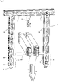
- FIG. 2a shows an exploded view of a mounting device 9 according to the invention, which has a horizontal profile 91 and two vertical profiles 92 connected thereto, as well as two adjusting devices 94 and a support profile 93.
- the horizontal profile 91 and the vertical profiles 92 are cut from a uniform metal profile.
- the metal profile comprises three side plates with round and rectangular openings 98, 99 arranged alternately in a grid. At the ends of the side plates, which are aligned parallel to one another, end strips 97 which are rotated in relation to one another and have teeth are provided.
- a C-profile is formed by the side plates and the end strips 97, which encloses a receiving channel 90 which is open on one side and has an at least approximately rectangular cross section.
- the two vertical profiles 92 arranged perpendicularly to the horizontal profile 91 are aligned in such a way that their receiving channels 90 face each other, so that the ends of the support profile 93 can be inserted into them on both sides and coupled to the adjusting device 94 .
- the in Figure 2b shown connecting device 7 which has a first and a second anchor element 72, 73 with threaded bores which can be connected to one another by a connecting screw 71.
- a connecting screw 71 Possible is also the use of two identical anchor elements 73.
- the anchor elements 72 or 73 are inserted into openings 99 in the horizontal profile 91 and a vertical profile 92 and pulled against one another by the connecting screw 71.
- the horizontal profile 91 and the vertical profiles 92 can therefore be stably connected to one another in a simple manner.
- Adjusting devices 94 are preferably arranged in the vertical profiles 92 or the receiving channels 90 provided therein, each of which comprises an anchor element 73 connected to the associated vertical profile 92, an adjusting screw 71 held rotatably in a threaded bore in the anchor element 73 and a bearing element 940, which is supported by the adjusting screw 71 can be slidably held within the receiving channel 90.
- the bearing element 941 comprises a receiving sleeve 941 which serves to receive the shank of the adjusting screw 71 and which is connected to a U-profile element 942 which is open at the top and serves to receive the support element 93 .
- the bearing element 940 which is aligned coaxially with the adjusting screw 71 , is designed in the shape of a fork and can accommodate an end piece of the support element 93 .
- the adjusting screw 71 By turning the adjusting screw 71, the held end piece of the support element 93 can be adjusted in height.
- the support profile 93 can be adjusted in height and inclination.
- the horizontal profile 91 is connected to a deflection roller 54 which has a running wheel 541 and a mounting part 542 .
- the deflection roller 54 is shown enlarged.
- the deflection roller 54 or the running wheel 541 can advantageously also be integrated into the horizontal profile 91 .
- the running wheel 541 is inserted into the receiving channel 90 of the horizontal profile 91 and fixed by the wheel axle 543, which is guided through adjacent openings 98. This results in the manufacture of the horizontal profile 91, a small additional effort, which is caused by the corresponding relief in the installation work is more than compensated.
- FIG. 3 shows the mounting device 9 mounted on a building ceiling Figure 2a during the adjustment of the support element 93.
- the left vertical profile 92 is shown in a sectional view, so that the adjustment device 94 mounted in the receiving channel 90 is visible. It shows that the shank of the adjusting screw 71 is aligned parallel to the axis of the associated vertical profile 92 and protrudes downwards so that the screw head can be gripped and rotated.
- FIG 4 shows the assembly device 9 of FIG 3 after inserting the support element 93 and lowering the two conductor rails 1.
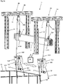
- Figure 5a shows an installation device 5 according to the invention with two assembly devices 9A, 9B mounted on the building ceiling and a working platform 51 which comprises a frame 512, a working platform 511 and a railing 513. Personnel can move on the working platform 511 in order to assemble the assembly devices 9A, 9B and then pull up one or more conductor rails.
- the working platform 51 is preferably adjustable in height and can preferably be moved on wheels or rollers.
- Two lifting devices 5A, 5B according to the invention are provided for pulling up the conductor rail 1, each of which has a pulling device or cable pulling device 52A; 52B with a traction means or traction cable 53A; 53B.
- the pulling devices 52A; 52B are detachably fastened to the working platform 51 in the area of the working platform 511 or to the railing 513 by means of connecting means 523, 524.
- the traction means 53A; 53B is not rolled up, but is held and carried away downwards during operation of the pulling devices 52A, 52B.
- the pulling devices 52A, 52B comprise a drive unit 521, typically an electric motor or as symbolically shown, a crank that is manually operable. Suitable traction devices that are used in the field of mountain rescue, for example, from the EP0624387A1 or the EP3212297B1 known.
- the traction means 53A; 53B are each guided to a conductor rail 1 via a deflection roller 54A, 54B, which is mounted on the associated mounting device 9A, 9B or is integrated therein.
- the ends 531A, 531B of the traction means 53A, 53B are designed as loops which enclose the conductor rail 1.
- a blocking unit prevents the drive shafts of the drive units 521 from being able to turn back.
- the drive shafts are preferably coupled to a gear wheel on which a rotatably mounted locking lever rests, which is raised by each tooth of the gear wheel when the train is tightened and then falls back between two teeth.
- the blocking lever engages between two teeth of the gear wheel and prevents further rotation of the drive shaft. If an electric motor fails or the manual operation of the drive crank is interrupted, the drive shaft is blocked immediately.
- the support profile 93 is then inserted into the vertical profiles 92. If the deflection rollers 54A, 54B are integrated into the horizontal profiles 91, the conductor rail 1 can be pulled all the way up to the stop on the horizontal profiles 91.
- Figure 5b shows the end of a traction device 53, which is connected by eyelets 5311 and hooks 5312 to a mounting loop 531'.
- the mounting loop 531' can be placed around the conductor rail 1, after which the hook 5312 can be inserted into the eyelets 5311 is introduced.
- One or more conductor rails 1 can therefore be connected to the traction means 53 quickly and safely.
- the conductor rail 1 preferably has a marking or indentation at the relevant assembly points, which serves to accommodate the cable by means of 53 or the assembly loop 531'.
- Figure 5c shows the installation device 5 in an enlarged view.
- the pulling devices 52A, 52B are shown to be detachably connected to the railing 513 of the work platform 51 by connecting parts or connecting rods 523 and snap hooks 524 .
- the drive devices 521 which are represented symbolically with a crank, include electric motors that are controlled synchronously or asynchronously by means of a control unit 50. Both pulling devices 52A, 52B can therefore be controlled by one person, preferably remotely.
- the other ends 531 are provided with a snap hook 524, by means of which the loop 531B or 531B, which is guided around the conductor rail 1, is closed.
- the traction means 53A or 53B is therefore guided around the conductor rail 1, after which the snap hook 524 is hooked into the traction means 53A or 53B.
- the connection to the busbar 1 can therefore be completed in a few simple steps.
- the conductor rods of high-quality busbars are e.g. cast in cast resin or epoxy cement or polymer concrete and thus achieve protection class IP68. Corresponding shaped elements can therefore be molded into the casting compound. In the case of busbars with a metal housing, this can be provided with the appropriate mounting elements.
Landscapes
- Engineering & Computer Science (AREA)
- Architecture (AREA)
- Civil Engineering (AREA)
- Structural Engineering (AREA)
- Conveying And Assembling Of Building Elements In Situ (AREA)
Description
- Die Erfindung betrifft eine Installationsvorrichtung für Stromschienen und ein Installationsverfahren zur Montage von Stromschienen mit dieser Installationsvorrichtung.
- Für die Übertragung von Strom mit hoher Leistung und Zuverlässigkeit werden Stromschienen als Übertragungsleitungen zwischen Transformatoren, Haupt- und Unterverteilern in Fabrikhallen, Gewerbe- und Verwaltungsgebäuden, oder auch als Steigleitungen in Hochbauten eingesetzt. Stromschienen und dafür vorgesehene Installationsvorrichtungen sind z.B. aus dem Produktkatalog "Niederspannungs-Schienenverteiler LANZ HE 2.5.2" der LANZ OENSINGEN AG vom Januar 2013 bekannt. Weitere Montagevorrichtungen sind aus dem Produktkatalog "LANZ die moderne Kabelführung" der LANZ OENSINGEN AG vom Oktober 2015 bekannt.
- Die Installation von Leitungen, Einrichtungen und Geräten am und im Baukörper wird traditionellerweise von Monteuren ausgeführt, die nicht auf die Installation von Stromschienen spezialisiert sind und die fallweise die benötigten Befestigungs- und Montagemittel beschaffen. Zum Anheben von schweren Stromschienen mit einem Gewicht von über 50 kg werden Hebevorrichtungen verwendet.
- Die
EP1589627B1 offenbart die nachstehend inFig. 1 gezeigte Montagevorrichtung 9 und eine Hebevorrichtung 4 mit zwei Tragvorrichtungen 41A, 41B, die der Installation von Stromschienen 1 im Bereich der Decke 8 eines Gebäudes dienen. Die Montagevorrichtung 9 umfasst ein an der Decke 8 montiertes Horizontalprofil 91 und zwei als Gewindestangen ausgebildete Vertikalprofile 92, zwischen die die Stromschienen 1 mittels der Tragvorrichtungen 41A, 41B und zugehörigen Zugseilen 44A, 44B hochgefahren werden können. - Zur Befestigung der Zugseile 44A, 44B ist oberhalb des Horizontalprofils 91 ein Montageprofil 99 eingesetzt. Die Zugseile 44A, 44B verlaufen über eine erste Umlenkrolle 95, die an einem ersten Ende des Montageprofils 99 gehalten ist, weiter über zwei Umlenkrollen 45A, 45B an den Tragvorrichtungen 41A, 41B und weiter zum zweiten Ende des Montageprofils 99.
- Die Stromschienen 1 sind auf der Frontseite von der ersten Tragvorrichtung 41A und auf der Rückseite von der zweiten Tragvorrichtung 41B gehalten.
- Die beiden Gewindestangen 92 sind nach dem Einführen der Stromschienen 1 mittels ersten Schraubenmuttern 921 und zweiten Schraubenmuttern 922 mit einem eingesetzten Tragprofil 93 verbindbar, auf das die gegen das Horizontalprofil 91 hochgefahrenen Stromschienen 1 heruntergefahren werden.
- Diese Hebevorrichtung 4 weist verschiedene Nachteile auf. Bevor die Stromschienen 1 hochgezogen werden können, ist ein erheblicher Installationsaufwand erforderlich. Zuerst ist das Montageprofil 99 an der Decke 8 zu montieren. In der gezeigten Ausführung ist dieses oberhalb des Horizontalprofils 91 eingesetzt, wo es Raum in Anspruch nimmt. Anschliessend sind die Tragvorrichtungen 41A, 41B bereitzustellen und die Zugseile 44A, 44B zu montieren.
- In der Folge müssen die schweren Stromschienen 1 angehoben und auf die Tragvorrichtungen 41A, 41B abgelegt werden. Erst jetzt können die Tragvorrichtungen 41A, 41B mit den Stromschienen 1 angehoben werden. Nun ist aber zu beachten, dass ein Anheben der Tragvorrichtungen 41A, 41B durch kräftiges Personal äusserst gefährlich ist. Bei einem Missgeschick, z.B. bei einem versehentlichen Loslassen eines Zugseils oder bei einem ungleichmässigen Hochziehen der Tragvorrichtungen 41A, 41B könnten die Stromschienen 1 von den Tragvorrichtungen 41A, 41B fallen und einerseits Personen verletzen und andererseits durch den Aufprall zerstört werden.
- Zu beachten ist ferner, dass die Tragvorrichtungen 41A, 41B, die mittels der Umlenkrollen 45A, 45B von den Zugseilen 44A, 44B gehalten sind, nicht auf die eine oder andere Seite abkippen. Die Tragvorrichtungen 41A, 41B sind daher sicherheitshalber z.B. durch weitere Seile in horizontaler Ausrichtung zu halten.
- Um diese Probleme zu vermeiden wurde in der
EP1589627B1 auch vorgeschlagen, jede der Tragvorrichtungen 41A, 41B mit zwei Antriebsaggregaten zu versehen. Diese Lösung ist jedoch noch wesentliche aufwendiger als die Lösung ohne mitgeführte Antriebsaggregate. - Nebst dem Herstellungsaufwand, Kostenaufwand, und Bedienungsaufwand für die Hebevorrichtung 4 gemäss der
EP1589627B1 ergibt sich zudem ein entsprechender Transportaufwand. Die Tragvorrichtungen 41A, 41B nehmen Raum in Anspruch und weisen ein erhebliches Gewicht auf. Hinsichtlich der Tragvorrichtungen 41A, 41B ist ferner zu beachten, dass diese nicht ganz bis zur Decke 8 angehoben werden können, weshalb mehr Raum für die Installation der Stromschienen 1 beansprucht wird. - Hinsichtlich der Installation der Stromschienen ist weiter zu beachten, dass zwei Arbeitsprozesse vorliegen. Einerseits müssen die Montagevorrichtungen an der Decke montiert werden. Andererseits müssen die Stromschienen angehoben werden und die Montagevorrichtungen bedient werden. D.h., das Tragprofil muss vor dem Hochziehen der Stromschienen entfernt und nach dem Hochziehen der Stromschienen wieder eingesetzt werden. Eine Montagegruppe ist daher für die Installation der Montagevorrichtungen vorzusehen und eine weitere Montagegruppe ist für das Anheben der Stromschienen besorgt, während zumindest eine weitere Person, auf einer Leiter stehend, die Montagevorrichtung bzw. das Tragprofil betätigt. Die Installation der Stromschienen mit der bekannten Vorrichtung ist daher arbeitsintensiv und mit Risiken verbunden. Eine weitere Installationsvorrichtung für die Befestigung von Stromschienen an einer Decke ist auch in
EP1905723A1 offenbart. - Der vorliegenden Erfindung liegt daher die Aufgabe zugrunde, eine verbesserte Vorrichtung für die Installation von Stromschienen und ein verbessertes Installationsverfahren anzugeben, mittels dessen Stromschienen in einer Montagevorrichtung montierbar sind.
- Die Installationsvorrichtung soll einfach ausgestaltet sein und nur einen geringen Materialaufwand und Kostenaufwand verursachen. Ferner soll die Installationsvorrichtung rasch und bequem einsetzbar sein.
- Es sollen an einer Baustelle bereits vorhandene Hilfsvorrichtungen vorteilhaft einsetzbar sein, ohne dass neue Vorrichtungen geschaffen werden müssen. Das für die Installation benötigte Installationsmaterial soll kaum Raum in Anspruch nehmen und bequem zum Installationsort transportierbar sein. Durch Vermeidung voluminöser Vorrichtungsteile soll es möglich sein, die Stromschienen maximal bis zur Decke hochzuziehen.
- Die Stromschienen sollen ohne Sicherheitsrisiken installierbar sein. Auch bei Fehlmanipulationen sollen die Stromschienen stets gesichert sein.
- Die Stromschienen sollen zudem mit einfachen Mitteln maschinell hochgefahren werden können, sodass eine Installation ohne Kraftaufwand möglich ist.
- Der Prozess des Hochfahrens der Stromschienen und der Prozess der Installation und Bedienung der Montagevorrichtungen, die zum Halten der Stromschienen an einer Decke vorgesehen sind, sollen miteinander kombinierbar sein, sodass sich der gesamte Installationsprozess vereinfacht und weniger Personal benötigt wird.
- Diese Aufgabe wird mit einer Installationsvorrichtung und einem Installationsverfahren gelöst, welche die in Anspruch 1 bzw. 12 angegebenen Merkmale aufweisen. Vorteilhafte Ausgestaltungen der Erfindung sind in weiteren Ansprüchen angegeben.
- Die für die Montage wenigstens einer Stromschiene vorgesehene Installationsvorrichtung umfasst Montagevorrichtungen, die an einer Gebäudedecke montiert sind, zwei Hebevorrichtungen, die je ein Zugmittel und je eine mit der zugehörigen Montagevorrichtung verbundene Umlenkrolle aufweisen.
- Erfindungsgemäss ist wenigstens eine Arbeitsbühne mit einer Arbeitsplattform und gegebenenfalls einem Geländer vorgesehen, an der im Bereich der Arbeitsplattform für jede der Hebevorrichtungen durch Verbindungsmittel eine Zugvorrichtung befestigt ist, mittels der das zugehörige Zugmittel, das über die zugehörige Umlenkrolle geführt ist und das mit einem Endstück mit der wenigstens einen Stromschiene verbindbar ist, anziehbar ist, um die wenigstens eine Stromschiene in die Montagevorrichtungen hochzuziehen, in denen sie fixierbar ist.
- Mit der erfindungsgemässen Installationsvorrichtung können schwere Stromschienen rasch und sicher installiert werden. Mittels der Hebebühne können die Montagevorrichtungen an der Gebäudedecke montiert, anschliessend die Stromschienen hochgefahren werden und weiter die notwendigen Manipulationen an den Montagevorrichtungen vorgenommen werden.
- Durch Verbindung der Zugvorrichtungen mit der Arbeitsbühne werden die Zugvorrichtungen gesichert und fixiert. Vorzugsweise werden lösbare Verbindungsmittel, wie Karabinerhaken, vorgesehen, die mit der Struktur, gegebenenfalls dem Geländer der Arbeitsbühne verbunden werden. Die Zugvorrichtungen können daher bedarfsweise für die Installation der Stromschienen eingesetzt und anschliessend wieder entfernt werden.
- Die Arbeitsbühne, die ein relativ grosses Eigengewicht aufweist, bildet das Gegengewicht zu den hochgezogenen Stromschienen. Sofern erforderlich, wird das Gewicht der Arbeitsbühne durch Ballast erhöht. Erfindungsgemäss wird die Arbeitsbühne somit funktional mit den Zugvorrichtungen kombiniert, sodass das wesentliche Problem der Fixierung und Sicherung der Zugvorrichtungen gelöst ist. Die Arbeitsbühne weist vorzugsweise Rollen oder Räder auf, sodass sie leicht an einen Installationsstandort gefahren oder bedarfsweise verschoben werden kann.
- Besonders vorteilhaft ist ferner, dass mit der erfindungsgemässen Installationsvorrichtung bzw. mit dem erfindungsgemässen Installationsverfahren nur wenig Personal benötigt wird. Grundsätzlich könnte die Installation der Stromschienen von einer einzigen Person ausgeführt werden. Dies insbesondere dann, wenn eine Steuervorrichtung vorhanden ist, welche es erlaubt, die Zugvorrichtungen bzw. deren Antriebsvorrichtungen synchron anzusteuern.
- Die Antriebsvorrichtungen sind drahtgebunden oder drahtlos je mit einer Steuereinheit verbunden oder verbindbar oder drahtgebunden oder drahtlos mit einer gemeinsamen Steuereinheit verbunden, mittels der die Antriebsvorrichtungen synchron und soweit erforderlich auch asynchron betreibbar sind.
- Die Zugvorrichtungen können eine manuell betätigbare Antriebsvorrichtung oder eine Antriebsvorrichtung mit einem Elektromotor umfassen. Die Antriebsvorrichtung kann in die Zugvorrichtung integriert oder mit dieser Bauweise koppelbar sein. Beispielsweise ist es möglich, eine Bohrmaschine oder eine Antriebsvorrichtung für einen Schraubendreher mit der Zugvorrichtung zu koppeln.
- Die Zugvorrichtung oder Seilwinde weist eine Sicherungsvorrichtung auf, die verhindert, dass das Zugmittel bzw. Zugseil unter der Last der Stromschiene zurückrutschen kann. Das Zugmittel wird beispielsweise mehrfach um eine Rolle gewickelt und in dieser festgeklemmt. Auf diese Weise wird das Zugmittel mit ansteigender Last nur noch stärker fest geklemmt und kann nicht mehr zurückweichen. Das Zugmittel wird nach Durchlaufen der Zugvorrichtung vorzugsweise freigegeben und nicht auf einer Rolle aufgewickelt. Durch Verzicht auf eine Wickelrolle können das Gewicht und die Dimensionen der Zugvorrichtung auf ein Minimum reduziert werden.
- Die mit der Arbeitsbühne verbindbaren Zugvorrichtungen können somit einfach ausgestaltet sein und selbst nur ein sehr geringes Gewicht aufweisen. Da Arbeitsbühnen in der Bauphase eines Projekts für verschiedene Arbeiten bereits vorhanden sind, muss das für die Installation der Stromschienen verantwortliche Personal nur sehr wenig und sehr leichtes Installationsmaterial zum Installationsort bringen. Eine voluminöse und relativ schwere Tragvorrichtung, wie sie aus dem Stand der Technik bekannt ist, wird vermieden. Das vom Installationspersonal mitzuführende Installationsmaterial passt in einen Koffer, der bequem zum Installationsort getragen werden kann.
- Durch die zuverlässige Sicherung der Installationsvorrichtung werden Risiken für das Personal vollständig ausgeschlossen. Beim Einsatz von Elektromotoren können die Stromschienen ferner ohne Kraftaufwand bequem installiert werden.
- Die den Stromschienen zugewandten Endstücke der Zugmittel sind vorzugsweise durch einen Haken mit einer vorzugsweise bandförmigen Schlaufe verbindbar, die dem Halten der Stromschiene dient. In bevorzugten Ausgestaltungen sind die Stromschienen mit Montageelementen versehen, die mit dem Zugmittel koppelbar sind.
- In vorzugsweisen Ausgestaltungen weisen die Montagevorrichtungen ein an der Gebäudedecke montierbares bzw. montiertes Horizontalprofil auf, das mit zwei voneinander beanstandeten Vertikalprofilen verbunden ist, an denen ein Tragprofil montiert ist, das die Stromschiene trägt und das zum Hochziehen der Stromschiene entfernbar und nach dem Hochziehen der Stromschiene wieder einsetzbar ist.
- Die Montagevorrichtungen weisen vorzugsweise Justiervorrichtungen auf, mittels denen Höhe, Lage und Ausrichtung der installierten Stromschienen justierbar sind, sodass benachbarte Stromschienen axial zueinander ausgerichtet und präzise miteinander verbunden werden können.
- Die für die Zugvorrichtungen bzw. die Zugmittel erforderlichen Umlenkrollen werden je mit dem zugehörigen Horizontalprofil lösbar verbunden oder sind je in das zugehörige Horizontalprofil integriert. Die Integration einer Umlenkrolle in ein Horizontalprofil, die mit geringem Kostenaufwand realisiert werden kann, führt zu einer weiteren Vereinfachung des Installationsverfahrens. Die Integration der Umlenkrolle in die Horizontalprofile hat ferner den Vorteil, dass die Stromschienen bis zu den Horizontalprofilen hochgezogen werden können.
- Das Installationsverfahren umfasst daher die folgenden Verfahrensschritte, von denen einige untereinander austauschbar sind. Insbesondere sind die Schritte zwei bis fünf beliebig untereinander austauschbar.
- Eine Arbeitsbühne, die eine Arbeitsplattform und gegebenenfalls ein Geländer umfasst, wird bereitgestellt.
- Durch vorzugsweise lösbare Verbindungsmittel werden zwei Zugvorrichtungen, die je mit einem Zugmittel versehen sind oder versehen werden, im Bereich der Arbeitsplattform mit der Arbeitsbühne verbunden.
- Wenigstens zwei Montagevorrichtungen, die der Installation der Stromschiene dienen und die dazu je ein Tragprofil aufweisen, werden an der Gebäudedecke montiert.
- Die Montagevorrichtungen werden an der Position, an der die Stromschiene hochzuziehen ist, je mit einer Umlenkrolle versehen.
- Die Zugmittel werden in die Umlenkrollen eingelegt und mit der zu installierenden Stromschiene verbunden.
- Die Zugvorrichtungen werden betätigt, um die Stromschiene hochzuziehen.
- Abschliessend wird die Stromschiene in den Montagevorrichtungen fixiert und gegebenenfalls in der Höhe, Lage und Ausrichtung justiert.
- Nachfolgend wird die Erfindung anhand von Zeichnungen näher erläutert. Dabei zeigt:
- Fig. 1
- die aus der
EP1589627B1 bekannte Montagevorrichtung 9, die eingangs beschrieben wurde; - Fig. 2a
- eine Explosionsdarstellung einer erfindungsgemässen Montagevorrichtung 9, die ein Horizontalprofil 91 und zwei damit verbundene Vertikalprofile 92 sowie ein Tragprofil 93 und zwei Justiervorrichtungen 94 aufweist;
- Fig. 2b
- eine Verbindungsvorrichtung 7 mit einem ersten und einem zweiten Ankerelement 72, 73, die in Öffnungen 99 im Horizontalprofil 91 und den Vertikalprofilen 92 verankerbar und durch eine Verbindungsschraube 71 miteinander verbindbar sind, um das Horizontalprofil 91 und die Vertikalprofile 92 der Montagevorrichtung 9 von
Fig. 2 gegenseitig zu fixieren; - Fig. 3
- die Montagevorrichtung 9 von
Fig. 2a , mit dem linken Vertikalprofil 92 in Schnittdarstellung gezeigt, und zwei angehobene Stromschienen 1 während der Justierung des Tragelements 93; - Fig. 4
- die Montagevorrichtung 9 von
Fig. 3 nach dem Einsetzen des Tragelements 93 und dem Absenken der beiden Stromschienen 1; - Fig. 5a
- eine erfindungsgemässe Installationsvorrichtung 5 mit zwei an der Gebäudedecke befestigten Montagevorrichtungen 9A, 9B und zwei Hebevorrichtungen 5A, 5B, die je eine auf einer Arbeitsbühne 51 befestigte Zugvorrichtung 52A; 52B mit einem Zugmittel 53A, 53B umfassen, das über eine Umlenkrolle 54A; 54B an der zugehörigen Montagevorrichtung 9A, 9B zu einer Stromschiene 1 geführt ist;
- Fig. 5b
- das Ende eines Zugmittels 53, welches durch Ösen 5311 und Haken 5312 mit einer Montageschlaufe 531' verbunden ist; und
- Fig. 5c
- die Installationsvorrichtung 5 von
Fig. 5a in vergrösserter Darstellung. -
Fig. 1 zeigt die eingangs beschriebene Installationsvorrichtung, die aus derEP1589627B1 bekannt ist. -
Fig. 2a zeigt eine Explosionsdarstellung einer erfindungsgemässen Montagevorrichtung 9, die ein Horizontalprofil 91 und zwei damit verbundene Vertikalprofile 92 sowie zwei Justiervorrichtungen 94 und ein Tragprofil 93 aufweist. - Das Horizontalprofil 91 und die Vertikalprofile 92 sind von einem einheitlichen Metallprofil geschnitten. Das Metallprofil umfasst drei Seitenplatten mit runden und rechteckigen Öffnungen 98, 99, die alternierend in einem Raster angeordnet sind. An den Enden der parallel zueinander ausgerichteten Seitenplatten sind gegeneinander gedrehte Abschlussleisten 97 vorgesehen, die eine Verzahnung aufweisen. Durch die Seitenplatten und die Abschlussleisten 97 wird ein C-Profil gebildet, das einen einseitig geöffneten Aufnahmekanal 90 umschliesst, der einen zumindest annähernd rechteckförmigen Querschnitt aufweist. Die beiden senkrecht zum Horizontalprofil 91 angeordneten Vertikalprofile 92 sind derart ausgerichtet, dass deren Aufnahmekanäle 90 einander zugewandt sind, so dass das Tragprofil 93 mit seinen Enden beidseits in diese einführbar und mit der Justiervorrichtung 94 koppelbar ist.
- Zur Verbindung der Vertikalprofile 92 mit dem Horizontalprofil 91 ist die in
Fig. 2b gezeigte Verbindungsvorrichtung 7 vorgesehen, die ein erstes und ein zweites Ankerelement 72, 73 mit Gewindebohrungen aufweist, die durch eine Verbindungsschraube 71 miteinander verbindbar sind. Möglich ist auch die Verwendung von zwei gleichen Ankerelementen 73. Die Ankerelemente 72 oder 73 werden in Öffnungen 99 des Horizontalprofils 91 und eines Vertikalprofils 92 eingesetzt und durch die Verbindungsschraube 71 gegeneinander gezogen. Das Horizontalprofil 91 und die Vertikalprofile 92 können daher in einfacher Weise stabil miteinander verbunden werden. - In den Vertikalprofilen 92 bzw. den darin vorgesehenen Aufnahmekanälen 90 sind vorzugsweise Justiervorrichtungen 94 angeordnet, die je ein mit dem zugehörigen Vertikalprofile 92 verbundenes Ankerelement 73, eine in einer Gewindebohrung im Ankerelement 73 drehbar gehaltene Justierschraube 71 und ein Lagerelement 940 umfassen, das von der Justierschraube 71 innerhalb des Aufnahmekanals 90 verschiebbar gehalten werden kann.
- Das Lagerelement 941 umfasst eine Aufnahmehülse 941, die der Aufnahme des Schafts der Justierschraube 71 dient und die mit einem U-Profil-Element 942 verbunden ist, welches nach oben geöffnet ist und der Aufnahme des Tragelements 93 dient. Das koaxial zur Justierschraube 71 ausgerichtete Lagerelement 940 ist gabelförmig ausgebildet und kann ein Endstück des Tragelements 93 aufnehmen. Durch Drehen der Justierschraube 71 kann das gehaltene Endstück des Tragelements 93 in der Höhe verstellt werden. Durch Drehen der Justierschrauben 71 bei beiden Vertikalprofilen 92 kann das Tragprofil 93 in der Höhe und der Neigung verstellt werden.
- Etwa in der Mitte wird das Horizontalprofil 91 mit einer Umlenkrolle 54 verbunden, die ein Laufrad 541 und ein Montageteil 542 aufweist. Die Umlenkrolle 54 ist vergrössert dargestellt. Die Umlenkrolle 54 bzw. das Laufrad 541 kann vorteilhaft auch in das Horizontalprofil 91 integriert werden. Beispielsweise wird das Laufrad 541 in den Aufnahmekanal 90 des Horizontalprofils 91 eingesetzt und durch die Radachse 543, die durch benachbarte Öffnungen 98 hindurch geführt wird, fixiert. Dadurch resultiert bei der Herstellung des Horizontalprofils 91 ein geringer Mehraufwand, der durch die entsprechende Erleichterung bei den Installationsarbeiten mehr als kompensiert wird.
-
Fig. 3 zeigt die an einer Gebäudedecke montierte Montagevorrichtung 9 vonFig. 2a während der Justierung des Tragelements 93. Das linke Vertikalprofil 92 ist in Schnittdarstellung gezeigt, sodass die im Aufnahmekanal 90 montierte Justiervorrichtung 94 sichtbar ist. Es ist gezeigt, dass der Schaft der Justierschraube 71 achsparallel zum zugehörigen Vertikalprofil 92 ausgerichtet ist und diesen nach unten überragt, sodass der Schraubenkopf erfasst und gedreht werden kann. -
Fig. 4 zeigt die Montagevorrichtung 9 vonFig. 3 nach dem Einsetzen des Tragelements 93 und dem Absenken der beiden Stromschienen 1. -
Fig. 5a zeigt eine erfindungsgemässe Installationsvorrichtung 5 mit zwei an der Gebäudedecke montierten Montagevorrichtungen 9A, 9B und einer Arbeitsbühne 51, die ein Gestell 512, eine Arbeitsplattform 511 und ein Geländer 513 umfasst. Auf der Arbeitsplattform 511 kann sich Personal bewegen, um die Montagevorrichtungen 9A, 9B zu montieren und anschliessend eine oder mehrere Stromschienen hochzuziehen. Die Arbeitsbühne 51 ist vorzugsweise in der Höhe verstellbar und vorzugsweise auf Rädern oder Rollen verfahrbar. Zum Hochziehen der Stromschiene 1 sind zwei erfindungsgemässe Hebevorrichtungen 5A, 5B vorgesehen, die je eine Zugvorrichtung bzw. Seilzugvorrichtung 52A; 52B mit einem Zugmittel bzw. Zugseil 53A; 53B umfassen. - Die Zugvorrichtungen 52A; 52B sind an der Arbeitsbühne 51 ist im Bereich der Arbeitsplattform 511 bzw. am Geländer 513 durch Verbindungsmittel 523, 524 lösbar befestigt. Das Zugmittel 53A; 53B wird nicht aufgerollt, sondern festgehalten und beim Betrieb der Zugvorrichtungen 52A, 52B nach unten weggeführt. Die Zugvorrichtungen 52A, 52B umfassen eine Antriebseinheit 521, typischerweise einen Elektromotor oder, wie symbolisch gezeigt, eine Kurbel, die manuell bedienbar ist. Geeignete Zugvorrichtungen, die im Bereich der Bergrettung eingesetzt werden, sind z.B. aus der
EP0624387A1 oder derEP3212297B1 bekannt. - Die Zugmittel 53A; 53B sind je über eine Umlenkrolle 54A, 54B, die an der zugehörigen Montagevorrichtung 9A, 9B montiert oder darin integriert ist, zu einer Stromschiene 1 geführt. Die Enden 531A, 531B der Zugmittel 53A, 53B sind als Schlaufen ausgebildet, welche die Stromschiene 1 umschliessen.
- Durch synchronen Betrieb der Zugvorrichtungen 52A, 52B kann die Stromschiene 1 horizontal ausgerichtet nach oben gefahren werden. Durch eine Blockiereinheit wird verhindert, dass die Antriebswellen der Antriebseinheiten 521 zurückdrehen können. Die Antriebswellen sind vorzugsweise mit einem Zahnrad gekoppelt, an dem ein drehbar gelagerter Blockierhebel anliegt, der beim Anziehen des Zug mittels durch jeden Zahn des Zahnrades angehoben wird und dann zurück zwischen zwei Zähne fällt. Sobald die Antriebswelle zurückdreht, verrastet der Blockierhebel zwischen zwei Zähnen des Zahnrads und verhindert dadurch eine weitere Drehung der Antriebswelle. Sollte ein Elektromotor ausfallen oder die manuelle Bedienung der Antriebskurbel unterbrochen werden, so wird die Antriebswelle sofort blockiert.
- Wie dies gezeigt ist, wird die Stromschiene 1 nach Betätigung der Zugvorrichtungen 52A; 52B bis zu den Umlenkrollen 54A, 54B nach oben gezogen werden. Wie
Fig. 4 zeigt, wird anschliessend das Tragprofil 93 in die Vertikalprofile 92 eingesetzt. Sofern die Umlenkrollen 54A, 54B in die Horizontalprofile 91 integriert werden, kann die Stromschiene 1 bis ganz nach oben bis zum Anschlag an den Horizontalprofilen 91 gezogen werden. -
Fig. 5b zeigt das Ende eines Zugmittels 53, welches durch Ösen 5311 und Haken 5312 mit einer Montageschlaufe 531' verbunden ist. Die Montageschlaufe 531' kann um die Stromschiene 1 gelegt werden, wonach der Haken 5312 in die Ösen 5311 eingeführt wird. Eine oder mehrere Stromschiene 1 können daher rasch und sicher mit den Zugmitteln 53 verbunden werden. Die Stromschiene 1 weist an den betreffenden Montagestellen vorzugsweise eine Markierung oder Einformung auf, die der Aufnahme des Zug mittels 53 oder der Montageschlaufe 531' dient. -
Fig. 5c zeigt die Installationsvorrichtung 5 in vergrösserter Darstellung. Es ist gezeigt, dass die Zugvorrichtungen 52A, 52B durch Verbindungsteile oder Verbindungsstäbe 523 und Karabinerhaken 524 lösbar mit dem Geländer 513 der Arbeitsbühne 51 verbunden sind. Die Antriebsvorrichtungen 521, die symbolisch mit einer Kurbel dargestellt sind, umfassen Elektromotoren, die mittels einer Steuereinheit 50 synchron oder asynchron angesteuert werden. Beide Zugvorrichtungen 52A, 52B können daher von einer Person gesteuert, vorzugsweise ferngesteuert werden. - Es ist gezeigt, dass beim Hochziehen der Stromschiene 1 die Enden 532A, 532B der Zugmittel 53A, 53B nach unten weggeführt werden.
- Die anderen Enden 531 sind mit einem Karabinerhaken 524 versehen, mittels dessen die um die Stromschiene 1 herumgeführt Schlaufe 531B bzw. 531B abgeschlossen ist. Das Zugmittel 53A bzw. 53B wird daher um die Stromschiene 1 herumgeführt, wonach der Karabinerhaken 524 in das Zugmittel 53A bzw. 53B eingehängt wird. Die Verbindung mit der Stromschiene 1 kann daher mit wenigen Handgriffen vollzogen werden.
- Strichpunktiert ist ferner gezeigt, dass die Enden 531A, 531B der Zugmittel 53A, 53B oder gegebenenfalls Schlaufen gemäss
Fig. 5b , durch Montageelemente 10 im Körper der Stromschiene 1, wie Montageringe, Montageöffnungen, Montagehaken oder dergleichen, hindurch geführt oder darin eingehängt werden können. - Die Leitungsstäbe qualitativ hochwertiger Stromschienen sind z.B. in Giessharz oder Epoxyzement bzw. Polymerbeton eingegossen und erreichen dadurch den Schutzgrad IP68. In die Gussmasse können daher entsprechende Formelemente eingeformt werden. Bei Stromschienen mit einem Metallgehäuse, kann dieses mit entsprechenden Montageelementen versehen werden.
Claims (15)
- Installationsvorrichtung (5) für die Montage wenigstens einer Stromschiene (1) mit Montagevorrichtungen (9A, 9B), die an einer Gebäudedecke (8) montierbar sind, mit zwei Hebevorrichtungen (5A, 5B), die je ein Zugmittel (53A, 53B) und je eine mit der zugehörigen Montagevorrichtung (9A; 9B) verbundene Umlenkrolle (54A; 54B) aufweisen, dadurch gekennzeichnet, dass wenigstens eine Arbeitsbühne (51) mit einer Arbeitsplattform (511) und gegebenenfalls einem Geländer (513) vorgesehen ist, an der im Bereich der Arbeitsplattform (511) für jede der Hebevorrichtungen (5A, 5B) durch Verbindungsmittel (523, 524) eine Zugvorrichtung (52A; 52B) befestigt ist, mittels der das zugehörige Zugmittel (53A; 53B), das über die zugehörige Umlenkrolle (54A; 54B) geführt ist und das mit einem Endstück (531A; 531B) mit der wenigstens einen Stromschiene (1) verbindbar ist, anziehbar ist, um die wenigstens eine Stromschiene (1) in die Montagevorrichtungen (9A, 9B) hochzuziehen, in denen sie fixierbar ist.
- Installationsvorrichtung (5) nach Anspruch 1, dadurch gekennzeichnet, dass die Zugvorrichtungen (52A; 52B) je eine Antriebsvorrichtung (521) für den motorischen oder manuellen Antrieb umfassen.
- Installationsvorrichtung (5) nach Anspruch 2, dadurch gekennzeichnet, dass die Antriebsvorrichtungen (521) drahtgebunden oder drahtlos je mit einer Steuereinheit (50) verbunden oder verbindbar sind oder dass die Antriebsvorrichtungen (521) drahtgebunden oder drahtlos mit einer gemeinsamen Steuereinheit (50) verbunden sind, mittels derer die Antriebsvorrichtungen (521) synchron betreibbar sind.
- Installationsvorrichtung (5) nach Anspruch 1, 2 oder 3, dadurch gekennzeichnet, dass die Zugvorrichtungen (52A; 52B) das Zugmittel (53A; 53B) mit einer Rolle halten oder dass das von den Zugvorrichtungen (52A; 52B) gehaltene Zugmittel (53A; 53B), gegebenenfalls eine Zugrolle einfach oder mehrfach umschliessend, die Zugvorrichtungen (52A; 52B) durchläuft.
- Installationsvorrichtung (5) nach einem der Ansprüche 1 - 4, dadurch gekennzeichnet, dass die Zugvorrichtungen (52A; 52B) durch lösbare Verbindungsmittel, wie Karabinerhaken (524) mit der Struktur, gegebenenfalls einem Geländer (513), der Arbeitsbühne (51) verbunden sind.
- Installationsvorrichtung (5) nach einem der Ansprüche 1 - 5, dadurch gekennzeichnet, dass die Zugmittel (53A; 53B) Seile und die Zugvorrichtungen (52A; 52B) Seilwinden sind.
- Installationsvorrichtung (5) nach einem der Ansprüche 1 - 6, dadurch gekennzeichnet, dass die Arbeitsbühne auf Rädern verfahrbar ist.
- Installationsvorrichtung (5) nach einem der Ansprüche 1 - 7, dadurch gekennzeichnet, dass die den Stromschienen (1) zugewandten Endstücke (531A, 531B) der Zugmittel (53A; 53B) durch einen Haken (5312) mit einer vorzugsweise bandförmigen Schlaufe (531') verbindbar sind, die dem Halten der Stromschiene (1) dient oder dass die den Stromschienen (1) zugewandten Endstücke (531A, 531B) der Zugmittel (53A; 53B) mit Montageelementen (10) der Stromschiene (1) verbindbar sind.
- Installationsvorrichtung (5) nach einem der Ansprüche 1 - 8, dadurch gekennzeichnet, dass die Montagevorrichtungen (9A; 9b) ein an der Gebäudedecke (8) montierbares Horizontalprofil (91) aufweisen, das mit zwei voneinander beanstandeten Vertikalprofilen (92) verbunden ist, an denen ein Tragprofil (93) montiert ist, das die Stromschiene (1) trägt und das zum Hochziehen der Stromschiene (1) entfernbar und nach dem Hochziehen der Stromschiene (1) wieder einsetzbar ist.
- Installationsvorrichtung (5) nach einem der Ansprüche 1 - 9, dadurch gekennzeichnet, dass die Montagevorrichtungen (9A; 9b) Justiervorrichtungen (94) aufweisen, mittels denen Höhe, Lage und Ausrichtung der installierten Stromschienen (1) justierbar sind.
- Installationsvorrichtung (5) nach einem der Ansprüche 1 - 10, dadurch gekennzeichnet, dass die Umlenkrollen (54A, 54B) je mit dem zugehörigen Horizontalprofil (91) lösbar verbunden sind oder dass die Umlenkrollen (54A, 54B) je in das zugehörige Horizontalprofil (91) integriert sind.
- Verfahren zur Installation einer Stromschiene (1) mit einer Installationsvorrichtung (5) nach einem der Ansprüche 1 - 11, dadurch gekennzeichnet,- dass eine Arbeitsbühne (51) mit einer Arbeitsplattform (511) und gegebenenfalls einem Geländer (513) bereitgestellt wird;- dass durch vorzugsweise lösbare Verbindungsmittel (523, 524) zwei Zugvorrichtungen (52A, 52B), die je mit einem Zugmittel (53A; 53B) versehen sind oder versehen werden, im Bereich der Arbeitsplattform (511) mit der Arbeitsbühne (51) verbunden werden;- dass wenigstens zwei Montagevorrichtungen (9A, 9b), die der Installation der Stromschiene (1) dienen und die dazu je ein Tragprofil (93) aufweisen, an der Gebäudedecke (8) montiert werden;- dass die Montagevorrichtungen (9A, 9b) an der Position, an der die Stromschiene (1) hochzuziehen ist, je mit einer Umlenkrolle (54A; 54B) versehen werden;- dass die Zugmittel (53A; 53B) in die Umlenkrollen (54A; 54B) eingelegt und mit der zu installierenden Stromschiene (1) verbunden werden;- dass die Zugvorrichtungen (52A, 52B) betätigt werden, um die Stromschiene (1) hochzuziehen; und- dass die Stromschiene (1) in den Montagevorrichtungen (9A, 9b) fixiert wird.
- Installationsverfahren (5) nach Anspruch 12, dadurch gekennzeichnet, dass die Montagevorrichtungen (9A, 9b), je ein Horizontalprofil (91), zwei damit verbundene Vertikalprofile (92) sowie ein mit den Vertikalprofilen (92) verbindbares Tragprofil (93) umfassen und dass die Horizontalprofile (91) an der Gebäudedecke (8) montiert und vorzugsweise in der Mitte mit der Umlenkrolle (54A, 54B) versehen werden oder dass die bereits mit den Umlenkrollen (54 A, 54 B) versehen Horizontalprofile (91) an der Gebäudedecke (8) montiert werden.
- Installationsverfahren (5) nach Anspruch 12 oder 13, dadurch gekennzeichnet, dass die Zugvorrichtungen (52A, 52B) je mit einer elektrisch betriebenen Antriebsvorrichtung (521) versehen sind, die je von einer individuell vorgesehenen Steuereinheit (50) oder gemeinsam genutzten Steuereinheit (50) gesteuert werden, um die Stromschiene (1) hochzuziehen.
- Installationsverfahren (5) nach Anspruch 12, 13 oder 14, dadurch gekennzeichnet, dass die Tragprofile (93) vor dem Hochziehen der Stromschiene (1) entfernt und nach dem Hochziehen der Stromschiene (1) in die Montagevorrichtungen (9A, 9B) eingesetzt wird und dass die Montagevorrichtungen (9A; 9b) Justiervorrichtungen (94) aufweisen, mittels denen Höhe, Lage und Ausrichtung der auf den Tragprofile ruhenden Stromschiene (1) bedarfsweise justiert werden.
Priority Applications (1)
| Application Number | Priority Date | Filing Date | Title |
|---|---|---|---|
| EP19205053.2A EP3813210B1 (de) | 2019-10-24 | 2019-10-24 | Installationsvorrichtung für stromschienen sowie installationsverfahren |
Applications Claiming Priority (1)
| Application Number | Priority Date | Filing Date | Title |
|---|---|---|---|
| EP19205053.2A EP3813210B1 (de) | 2019-10-24 | 2019-10-24 | Installationsvorrichtung für stromschienen sowie installationsverfahren |
Publications (2)
| Publication Number | Publication Date |
|---|---|
| EP3813210A1 EP3813210A1 (de) | 2021-04-28 |
| EP3813210B1 true EP3813210B1 (de) | 2022-09-21 |
Family
ID=68342776
Family Applications (1)
| Application Number | Title | Priority Date | Filing Date |
|---|---|---|---|
| EP19205053.2A Active EP3813210B1 (de) | 2019-10-24 | 2019-10-24 | Installationsvorrichtung für stromschienen sowie installationsverfahren |
Country Status (1)
| Country | Link |
|---|---|
| EP (1) | EP3813210B1 (de) |
Family Cites Families (4)
| Publication number | Priority date | Publication date | Assignee | Title |
|---|---|---|---|---|
| DE4315952C2 (de) | 1993-05-12 | 1997-05-07 | Anton Staltmeir | Abseil- und Aufseilgerät |
| ATE357764T1 (de) | 2004-04-20 | 2007-04-15 | Zurecon Ag | Befestigungs- und hebevorrichtung für stromschienen |
| ATE533724T1 (de) * | 2006-09-30 | 2011-12-15 | Zurecon Ag | Hebevorrichtung für die montage von stromschienen |
| DE202015001685U1 (de) | 2015-03-05 | 2015-03-23 | Mittelmann Sicherheitstechnik Gmbh & Co. Kg | Abseilgerät |
-
2019
- 2019-10-24 EP EP19205053.2A patent/EP3813210B1/de active Active
Also Published As
| Publication number | Publication date |
|---|---|
| EP3813210A1 (de) | 2021-04-28 |
Similar Documents
| Publication | Publication Date | Title |
|---|---|---|
| EP2556008B1 (de) | Vorrichtung und verfahren zum errichten eines turms einer windenergieanlage | |
| WO2004067954A1 (de) | Verfahren zur kranlosen montage eines rotorblattes einer windenergieanlage | |
| DE102010031208A1 (de) | Vorrichtung und Verfahren zur Aufstiegssicherung | |
| WO2006097505A1 (de) | Arbeitsbühne | |
| EP1905723B1 (de) | Hebevorrichtung für die Montage von Stromschienen | |
| AT510762B1 (de) | Seilzugeinrichtung, insbesondere prospektzuganlage für eine bühne oder dgl. | |
| WO2018019877A1 (de) | Befestigungselement | |
| EP3813210B1 (de) | Installationsvorrichtung für stromschienen sowie installationsverfahren | |
| DE102017124233A1 (de) | Schelleneinheit für Hydraulikleitungen | |
| EP1589627B1 (de) | Befestigungs- und Hebevorrichtung für Stromschienen | |
| DE102017128143B3 (de) | Wartungsplattform zur Wartung von Einbauten in einem Turm für eine Windenergieanlage und Anordnung einer Wartungsplattform | |
| DE102017009291A1 (de) | Windenmontagerahmen und Windenanordnung | |
| WO2017174490A1 (de) | Befestigungselement für wanschalungen | |
| DE10243356A1 (de) | Zerlegbares Gerüst | |
| DE202017107205U1 (de) | Befestigungsvorrichtung für Stromschienen | |
| DE102012004144B4 (de) | Vorrichtung zum Einbau von mindestens einem Seil, insbesondere im Bereich des Gerüstbaus, und Verfahren für den Einbau von Seilen | |
| DE102015101788B4 (de) | Sicherheitssystem für den Hochbau und dessen Verwendung | |
| WO2005045160A1 (de) | Deckentisch einer betonschalung und vorrichtung zum versetzen des deckentischs | |
| EP2482130A1 (de) | Flexibles Zugsystem für Bildwandsysteme und Verfahren zur Montage von Bildwandsystemen | |
| DE4430759C2 (de) | Verfahren und Vorrichtung zum Auswechseln eines Mastkopfes eines Winkeltragmastes einer Hochspannungsfreileitung | |
| EP2458107A2 (de) | Markise mit Abstützung und magnetischer Fixierung | |
| WO2020094735A1 (de) | Hebezeugbefestigung und hebezeug für windkraftturbinen | |
| DE102009032426B3 (de) | Vorrichtung zur Montage und/oder Demontage von Ballast an einem Kran und Turmdrehkran mit einer derartigen Vorrichtung | |
| EP3133706A1 (de) | Verfahren zur installation von stromschienen | |
| DE3215328A1 (de) | Sicherungsvorrichtung fuer absturzgefaehrdete personen |
Legal Events
| Date | Code | Title | Description |
|---|---|---|---|
| PUAI | Public reference made under article 153(3) epc to a published international application that has entered the european phase |
Free format text: ORIGINAL CODE: 0009012 |
|
| STAA | Information on the status of an ep patent application or granted ep patent |
Free format text: STATUS: THE APPLICATION HAS BEEN PUBLISHED |
|
| AK | Designated contracting states |
Kind code of ref document: A1 Designated state(s): AL AT BE BG CH CY CZ DE DK EE ES FI FR GB GR HR HU IE IS IT LI LT LU LV MC MK MT NL NO PL PT RO RS SE SI SK SM TR |
|
| AX | Request for extension of the european patent |
Extension state: BA ME |
|
| STAA | Information on the status of an ep patent application or granted ep patent |
Free format text: STATUS: REQUEST FOR EXAMINATION WAS MADE |
|
| 17P | Request for examination filed |
Effective date: 20211028 |
|
| RBV | Designated contracting states (corrected) |
Designated state(s): AL AT BE BG CH CY CZ DE DK EE ES FI FR GB GR HR HU IE IS IT LI LT LU LV MC MK MT NL NO PL PT RO RS SE SI SK SM TR |
|
| GRAP | Despatch of communication of intention to grant a patent |
Free format text: ORIGINAL CODE: EPIDOSNIGR1 |
|
| STAA | Information on the status of an ep patent application or granted ep patent |
Free format text: STATUS: GRANT OF PATENT IS INTENDED |
|
| RIC1 | Information provided on ipc code assigned before grant |
Ipc: H02G 5/00 20060101ALN20220318BHEP Ipc: H02G 3/00 20060101ALI20220318BHEP Ipc: H02G 1/00 20060101AFI20220318BHEP |
|
| INTG | Intention to grant announced |
Effective date: 20220406 |
|
| GRAS | Grant fee paid |
Free format text: ORIGINAL CODE: EPIDOSNIGR3 |
|
| GRAA | (expected) grant |
Free format text: ORIGINAL CODE: 0009210 |
|
| STAA | Information on the status of an ep patent application or granted ep patent |
Free format text: STATUS: THE PATENT HAS BEEN GRANTED |
|
| AK | Designated contracting states |
Kind code of ref document: B1 Designated state(s): AL AT BE BG CH CY CZ DE DK EE ES FI FR GB GR HR HU IE IS IT LI LT LU LV MC MK MT NL NO PL PT RO RS SE SI SK SM TR |
|
| REG | Reference to a national code |
Ref country code: GB Ref legal event code: FG4D Free format text: NOT ENGLISH |
|
| REG | Reference to a national code |
Ref country code: CH Ref legal event code: EP |
|
| REG | Reference to a national code |
Ref country code: DE Ref legal event code: R096 Ref document number: 502019005702 Country of ref document: DE |
|
| REG | Reference to a national code |
Ref country code: IE Ref legal event code: FG4D Free format text: LANGUAGE OF EP DOCUMENT: GERMAN |
|
| REG | Reference to a national code |
Ref country code: AT Ref legal event code: REF Ref document number: 1520441 Country of ref document: AT Kind code of ref document: T Effective date: 20221015 |
|
| REG | Reference to a national code |
Ref country code: LT Ref legal event code: MG9D |
|
| REG | Reference to a national code |
Ref country code: NL Ref legal event code: MP Effective date: 20220921 |
|
| PG25 | Lapsed in a contracting state [announced via postgrant information from national office to epo] |
Ref country code: SE Free format text: LAPSE BECAUSE OF FAILURE TO SUBMIT A TRANSLATION OF THE DESCRIPTION OR TO PAY THE FEE WITHIN THE PRESCRIBED TIME-LIMIT Effective date: 20220921 Ref country code: RS Free format text: LAPSE BECAUSE OF FAILURE TO SUBMIT A TRANSLATION OF THE DESCRIPTION OR TO PAY THE FEE WITHIN THE PRESCRIBED TIME-LIMIT Effective date: 20220921 Ref country code: NO Free format text: LAPSE BECAUSE OF FAILURE TO SUBMIT A TRANSLATION OF THE DESCRIPTION OR TO PAY THE FEE WITHIN THE PRESCRIBED TIME-LIMIT Effective date: 20221221 Ref country code: LV Free format text: LAPSE BECAUSE OF FAILURE TO SUBMIT A TRANSLATION OF THE DESCRIPTION OR TO PAY THE FEE WITHIN THE PRESCRIBED TIME-LIMIT Effective date: 20220921 Ref country code: LT Free format text: LAPSE BECAUSE OF FAILURE TO SUBMIT A TRANSLATION OF THE DESCRIPTION OR TO PAY THE FEE WITHIN THE PRESCRIBED TIME-LIMIT Effective date: 20220921 Ref country code: FI Free format text: LAPSE BECAUSE OF FAILURE TO SUBMIT A TRANSLATION OF THE DESCRIPTION OR TO PAY THE FEE WITHIN THE PRESCRIBED TIME-LIMIT Effective date: 20220921 |
|
| PG25 | Lapsed in a contracting state [announced via postgrant information from national office to epo] |
Ref country code: HR Free format text: LAPSE BECAUSE OF FAILURE TO SUBMIT A TRANSLATION OF THE DESCRIPTION OR TO PAY THE FEE WITHIN THE PRESCRIBED TIME-LIMIT Effective date: 20220921 Ref country code: GR Free format text: LAPSE BECAUSE OF FAILURE TO SUBMIT A TRANSLATION OF THE DESCRIPTION OR TO PAY THE FEE WITHIN THE PRESCRIBED TIME-LIMIT Effective date: 20221222 |
|
| PG25 | Lapsed in a contracting state [announced via postgrant information from national office to epo] |
Ref country code: SM Free format text: LAPSE BECAUSE OF FAILURE TO SUBMIT A TRANSLATION OF THE DESCRIPTION OR TO PAY THE FEE WITHIN THE PRESCRIBED TIME-LIMIT Effective date: 20220921 Ref country code: RO Free format text: LAPSE BECAUSE OF FAILURE TO SUBMIT A TRANSLATION OF THE DESCRIPTION OR TO PAY THE FEE WITHIN THE PRESCRIBED TIME-LIMIT Effective date: 20220921 Ref country code: PT Free format text: LAPSE BECAUSE OF FAILURE TO SUBMIT A TRANSLATION OF THE DESCRIPTION OR TO PAY THE FEE WITHIN THE PRESCRIBED TIME-LIMIT Effective date: 20230123 Ref country code: ES Free format text: LAPSE BECAUSE OF FAILURE TO SUBMIT A TRANSLATION OF THE DESCRIPTION OR TO PAY THE FEE WITHIN THE PRESCRIBED TIME-LIMIT Effective date: 20220921 Ref country code: CZ Free format text: LAPSE BECAUSE OF FAILURE TO SUBMIT A TRANSLATION OF THE DESCRIPTION OR TO PAY THE FEE WITHIN THE PRESCRIBED TIME-LIMIT Effective date: 20220921 |
|
| PG25 | Lapsed in a contracting state [announced via postgrant information from national office to epo] |
Ref country code: SK Free format text: LAPSE BECAUSE OF FAILURE TO SUBMIT A TRANSLATION OF THE DESCRIPTION OR TO PAY THE FEE WITHIN THE PRESCRIBED TIME-LIMIT Effective date: 20220921 Ref country code: PL Free format text: LAPSE BECAUSE OF FAILURE TO SUBMIT A TRANSLATION OF THE DESCRIPTION OR TO PAY THE FEE WITHIN THE PRESCRIBED TIME-LIMIT Effective date: 20220921 Ref country code: IS Free format text: LAPSE BECAUSE OF FAILURE TO SUBMIT A TRANSLATION OF THE DESCRIPTION OR TO PAY THE FEE WITHIN THE PRESCRIBED TIME-LIMIT Effective date: 20230121 Ref country code: EE Free format text: LAPSE BECAUSE OF FAILURE TO SUBMIT A TRANSLATION OF THE DESCRIPTION OR TO PAY THE FEE WITHIN THE PRESCRIBED TIME-LIMIT Effective date: 20220921 |
|
| REG | Reference to a national code |
Ref country code: DE Ref legal event code: R097 Ref document number: 502019005702 Country of ref document: DE |
|
| REG | Reference to a national code |
Ref country code: BE Ref legal event code: MM Effective date: 20221031 |
|
| PG25 | Lapsed in a contracting state [announced via postgrant information from national office to epo] |
Ref country code: NL Free format text: LAPSE BECAUSE OF FAILURE TO SUBMIT A TRANSLATION OF THE DESCRIPTION OR TO PAY THE FEE WITHIN THE PRESCRIBED TIME-LIMIT Effective date: 20220921 Ref country code: MC Free format text: LAPSE BECAUSE OF FAILURE TO SUBMIT A TRANSLATION OF THE DESCRIPTION OR TO PAY THE FEE WITHIN THE PRESCRIBED TIME-LIMIT Effective date: 20220921 Ref country code: LU Free format text: LAPSE BECAUSE OF NON-PAYMENT OF DUE FEES Effective date: 20221024 Ref country code: AL Free format text: LAPSE BECAUSE OF FAILURE TO SUBMIT A TRANSLATION OF THE DESCRIPTION OR TO PAY THE FEE WITHIN THE PRESCRIBED TIME-LIMIT Effective date: 20220921 |
|
| P01 | Opt-out of the competence of the unified patent court (upc) registered |
Effective date: 20230529 |
|
| PLBE | No opposition filed within time limit |
Free format text: ORIGINAL CODE: 0009261 |
|
| STAA | Information on the status of an ep patent application or granted ep patent |
Free format text: STATUS: NO OPPOSITION FILED WITHIN TIME LIMIT |
|
| PG25 | Lapsed in a contracting state [announced via postgrant information from national office to epo] |
Ref country code: DK Free format text: LAPSE BECAUSE OF FAILURE TO SUBMIT A TRANSLATION OF THE DESCRIPTION OR TO PAY THE FEE WITHIN THE PRESCRIBED TIME-LIMIT Effective date: 20220921 |
|
| 26N | No opposition filed |
Effective date: 20230622 |
|
| PG25 | Lapsed in a contracting state [announced via postgrant information from national office to epo] |
Ref country code: SI Free format text: LAPSE BECAUSE OF FAILURE TO SUBMIT A TRANSLATION OF THE DESCRIPTION OR TO PAY THE FEE WITHIN THE PRESCRIBED TIME-LIMIT Effective date: 20220921 |
|
| PG25 | Lapsed in a contracting state [announced via postgrant information from national office to epo] |
Ref country code: BE Free format text: LAPSE BECAUSE OF NON-PAYMENT OF DUE FEES Effective date: 20221031 |
|
| PG25 | Lapsed in a contracting state [announced via postgrant information from national office to epo] |
Ref country code: IE Free format text: LAPSE BECAUSE OF NON-PAYMENT OF DUE FEES Effective date: 20221024 |
|
| PGFP | Annual fee paid to national office [announced via postgrant information from national office to epo] |
Ref country code: FR Payment date: 20231026 Year of fee payment: 5 Ref country code: DE Payment date: 20231020 Year of fee payment: 5 Ref country code: CH Payment date: 20231102 Year of fee payment: 5 |
|
| PG25 | Lapsed in a contracting state [announced via postgrant information from national office to epo] |
Ref country code: CY Free format text: LAPSE BECAUSE OF FAILURE TO SUBMIT A TRANSLATION OF THE DESCRIPTION OR TO PAY THE FEE WITHIN THE PRESCRIBED TIME-LIMIT Effective date: 20220921 |