EP3812064A1 - Metallpulver für 3d-drucker, formartikel und verfahren zur herstellung des formartikels - Google Patents
Metallpulver für 3d-drucker, formartikel und verfahren zur herstellung des formartikels Download PDFInfo
- Publication number
- EP3812064A1 EP3812064A1 EP19811569.3A EP19811569A EP3812064A1 EP 3812064 A1 EP3812064 A1 EP 3812064A1 EP 19811569 A EP19811569 A EP 19811569A EP 3812064 A1 EP3812064 A1 EP 3812064A1
- Authority
- EP
- European Patent Office
- Prior art keywords
- metal
- metal powder
- particle
- metal particles
- powder
- Prior art date
- Legal status (The legal status is an assumption and is not a legal conclusion. Google has not performed a legal analysis and makes no representation as to the accuracy of the status listed.)
- Pending
Links
- 239000000843 powder Substances 0.000 title claims abstract description 146
- 229910052751 metal Inorganic materials 0.000 title claims abstract description 133
- 239000002184 metal Substances 0.000 title claims abstract description 133
- 238000004519 manufacturing process Methods 0.000 title claims description 13
- 239000002923 metal particle Substances 0.000 claims abstract description 106
- 239000002245 particle Substances 0.000 claims abstract description 84
- 238000009826 distribution Methods 0.000 claims abstract description 36
- 238000000034 method Methods 0.000 claims description 57
- WFKWXMTUELFFGS-UHFFFAOYSA-N tungsten Chemical compound [W] WFKWXMTUELFFGS-UHFFFAOYSA-N 0.000 claims description 17
- ZOKXTWBITQBERF-UHFFFAOYSA-N Molybdenum Chemical compound [Mo] ZOKXTWBITQBERF-UHFFFAOYSA-N 0.000 claims description 16
- 229910052721 tungsten Inorganic materials 0.000 claims description 15
- 239000010937 tungsten Substances 0.000 claims description 15
- 229910052750 molybdenum Inorganic materials 0.000 claims description 14
- 239000011733 molybdenum Substances 0.000 claims description 14
- 238000000465 moulding Methods 0.000 claims description 14
- 230000001186 cumulative effect Effects 0.000 claims description 11
- 239000010955 niobium Substances 0.000 claims description 7
- GUCVJGMIXFAOAE-UHFFFAOYSA-N niobium atom Chemical compound [Nb] GUCVJGMIXFAOAE-UHFFFAOYSA-N 0.000 claims description 7
- WUAPFZMCVAUBPE-UHFFFAOYSA-N rhenium atom Chemical compound [Re] WUAPFZMCVAUBPE-UHFFFAOYSA-N 0.000 claims description 7
- GUVRBAGPIYLISA-UHFFFAOYSA-N tantalum atom Chemical compound [Ta] GUVRBAGPIYLISA-UHFFFAOYSA-N 0.000 claims description 7
- 229910052758 niobium Inorganic materials 0.000 claims description 6
- 239000011164 primary particle Substances 0.000 claims description 6
- 229910052702 rhenium Inorganic materials 0.000 claims description 6
- 229910052715 tantalum Inorganic materials 0.000 claims description 6
- 239000011651 chromium Substances 0.000 claims description 5
- VYZAMTAEIAYCRO-UHFFFAOYSA-N Chromium Chemical compound [Cr] VYZAMTAEIAYCRO-UHFFFAOYSA-N 0.000 claims description 4
- 229910052804 chromium Inorganic materials 0.000 claims description 4
- 229910052720 vanadium Inorganic materials 0.000 claims description 3
- LEONUFNNVUYDNQ-UHFFFAOYSA-N vanadium atom Chemical compound [V] LEONUFNNVUYDNQ-UHFFFAOYSA-N 0.000 claims description 2
- 238000009825 accumulation Methods 0.000 abstract 2
- 238000007493 shaping process Methods 0.000 description 34
- 238000002844 melting Methods 0.000 description 32
- 230000008018 melting Effects 0.000 description 32
- 238000010146 3D printing Methods 0.000 description 30
- 238000012545 processing Methods 0.000 description 16
- 230000000052 comparative effect Effects 0.000 description 12
- 239000000463 material Substances 0.000 description 12
- 238000000227 grinding Methods 0.000 description 11
- 238000000110 selective laser sintering Methods 0.000 description 10
- 238000010894 electron beam technology Methods 0.000 description 9
- 238000000889 atomisation Methods 0.000 description 5
- 239000000470 constituent Substances 0.000 description 5
- 238000005259 measurement Methods 0.000 description 5
- 238000011049 filling Methods 0.000 description 4
- 230000004927 fusion Effects 0.000 description 4
- 239000010935 stainless steel Substances 0.000 description 4
- 229910001220 stainless steel Inorganic materials 0.000 description 4
- 239000011230 binding agent Substances 0.000 description 3
- 238000005469 granulation Methods 0.000 description 3
- 230000003179 granulation Effects 0.000 description 3
- 230000005484 gravity Effects 0.000 description 3
- 238000010438 heat treatment Methods 0.000 description 3
- 239000011347 resin Substances 0.000 description 3
- 229920005989 resin Polymers 0.000 description 3
- 238000007088 Archimedes method Methods 0.000 description 2
- CURLTUGMZLYLDI-UHFFFAOYSA-N Carbon dioxide Chemical compound O=C=O CURLTUGMZLYLDI-UHFFFAOYSA-N 0.000 description 2
- PXHVJJICTQNCMI-UHFFFAOYSA-N Nickel Chemical compound [Ni] PXHVJJICTQNCMI-UHFFFAOYSA-N 0.000 description 2
- 230000000694 effects Effects 0.000 description 2
- WHJFNYXPKGDKBB-UHFFFAOYSA-N hafnium;methane Chemical compound C.[Hf] WHJFNYXPKGDKBB-UHFFFAOYSA-N 0.000 description 2
- 230000001678 irradiating effect Effects 0.000 description 2
- 239000007788 liquid Substances 0.000 description 2
- 239000007769 metal material Substances 0.000 description 2
- 239000010936 titanium Substances 0.000 description 2
- GPPXJZIENCGNKB-UHFFFAOYSA-N vanadium Chemical compound [V]#[V] GPPXJZIENCGNKB-UHFFFAOYSA-N 0.000 description 2
- RYGMFSIKBFXOCR-UHFFFAOYSA-N Copper Chemical compound [Cu] RYGMFSIKBFXOCR-UHFFFAOYSA-N 0.000 description 1
- 229910001182 Mo alloy Inorganic materials 0.000 description 1
- RTAQQCXQSZGOHL-UHFFFAOYSA-N Titanium Chemical compound [Ti] RTAQQCXQSZGOHL-UHFFFAOYSA-N 0.000 description 1
- 229910001080 W alloy Inorganic materials 0.000 description 1
- 229910052769 Ytterbium Inorganic materials 0.000 description 1
- 229910045601 alloy Inorganic materials 0.000 description 1
- 239000000956 alloy Substances 0.000 description 1
- 229910052782 aluminium Inorganic materials 0.000 description 1
- XAGFODPZIPBFFR-UHFFFAOYSA-N aluminium Chemical compound [Al] XAGFODPZIPBFFR-UHFFFAOYSA-N 0.000 description 1
- 238000000149 argon plasma sintering Methods 0.000 description 1
- 230000015572 biosynthetic process Effects 0.000 description 1
- 229910002092 carbon dioxide Inorganic materials 0.000 description 1
- 239000001569 carbon dioxide Substances 0.000 description 1
- 238000009690 centrifugal atomisation Methods 0.000 description 1
- 150000001875 compounds Chemical class 0.000 description 1
- 229910052802 copper Inorganic materials 0.000 description 1
- 239000010949 copper Substances 0.000 description 1
- 238000005520 cutting process Methods 0.000 description 1
- 238000009689 gas atomisation Methods 0.000 description 1
- 238000007561 laser diffraction method Methods 0.000 description 1
- 239000000155 melt Substances 0.000 description 1
- 239000011812 mixed powder Substances 0.000 description 1
- 238000002156 mixing Methods 0.000 description 1
- 239000000203 mixture Substances 0.000 description 1
- 238000012986 modification Methods 0.000 description 1
- 230000004048 modification Effects 0.000 description 1
- 229910052759 nickel Inorganic materials 0.000 description 1
- 239000011148 porous material Substances 0.000 description 1
- 238000005245 sintering Methods 0.000 description 1
- 239000007787 solid Substances 0.000 description 1
- 238000006467 substitution reaction Methods 0.000 description 1
- 239000002344 surface layer Substances 0.000 description 1
- 238000010998 test method Methods 0.000 description 1
- 238000012360 testing method Methods 0.000 description 1
- 229910052719 titanium Inorganic materials 0.000 description 1
- XLYOFNOQVPJJNP-UHFFFAOYSA-N water Substances O XLYOFNOQVPJJNP-UHFFFAOYSA-N 0.000 description 1
- 238000009692 water atomization Methods 0.000 description 1
- NAWDYIZEMPQZHO-UHFFFAOYSA-N ytterbium Chemical compound [Yb] NAWDYIZEMPQZHO-UHFFFAOYSA-N 0.000 description 1
Images

Classifications
-
- B—PERFORMING OPERATIONS; TRANSPORTING
- B22—CASTING; POWDER METALLURGY
- B22F—WORKING METALLIC POWDER; MANUFACTURE OF ARTICLES FROM METALLIC POWDER; MAKING METALLIC POWDER; APPARATUS OR DEVICES SPECIALLY ADAPTED FOR METALLIC POWDER
- B22F1/00—Metallic powder; Treatment of metallic powder, e.g. to facilitate working or to improve properties
- B22F1/05—Metallic powder characterised by the size or surface area of the particles
- B22F1/052—Metallic powder characterised by the size or surface area of the particles characterised by a mixture of particles of different sizes or by the particle size distribution
-
- B—PERFORMING OPERATIONS; TRANSPORTING
- B22—CASTING; POWDER METALLURGY
- B22F—WORKING METALLIC POWDER; MANUFACTURE OF ARTICLES FROM METALLIC POWDER; MAKING METALLIC POWDER; APPARATUS OR DEVICES SPECIALLY ADAPTED FOR METALLIC POWDER
- B22F1/00—Metallic powder; Treatment of metallic powder, e.g. to facilitate working or to improve properties
- B22F1/06—Metallic powder characterised by the shape of the particles
- B22F1/065—Spherical particles
-
- B—PERFORMING OPERATIONS; TRANSPORTING
- B22—CASTING; POWDER METALLURGY
- B22F—WORKING METALLIC POWDER; MANUFACTURE OF ARTICLES FROM METALLIC POWDER; MAKING METALLIC POWDER; APPARATUS OR DEVICES SPECIALLY ADAPTED FOR METALLIC POWDER
- B22F9/00—Making metallic powder or suspensions thereof
- B22F9/02—Making metallic powder or suspensions thereof using physical processes
- B22F9/14—Making metallic powder or suspensions thereof using physical processes using electric discharge
-
- B—PERFORMING OPERATIONS; TRANSPORTING
- B33—ADDITIVE MANUFACTURING TECHNOLOGY
- B33Y—ADDITIVE MANUFACTURING, i.e. MANUFACTURING OF THREE-DIMENSIONAL [3-D] OBJECTS BY ADDITIVE DEPOSITION, ADDITIVE AGGLOMERATION OR ADDITIVE LAYERING, e.g. BY 3-D PRINTING, STEREOLITHOGRAPHY OR SELECTIVE LASER SINTERING
- B33Y10/00—Processes of additive manufacturing
-
- B—PERFORMING OPERATIONS; TRANSPORTING
- B33—ADDITIVE MANUFACTURING TECHNOLOGY
- B33Y—ADDITIVE MANUFACTURING, i.e. MANUFACTURING OF THREE-DIMENSIONAL [3-D] OBJECTS BY ADDITIVE DEPOSITION, ADDITIVE AGGLOMERATION OR ADDITIVE LAYERING, e.g. BY 3-D PRINTING, STEREOLITHOGRAPHY OR SELECTIVE LASER SINTERING
- B33Y70/00—Materials specially adapted for additive manufacturing
-
- B—PERFORMING OPERATIONS; TRANSPORTING
- B33—ADDITIVE MANUFACTURING TECHNOLOGY
- B33Y—ADDITIVE MANUFACTURING, i.e. MANUFACTURING OF THREE-DIMENSIONAL [3-D] OBJECTS BY ADDITIVE DEPOSITION, ADDITIVE AGGLOMERATION OR ADDITIVE LAYERING, e.g. BY 3-D PRINTING, STEREOLITHOGRAPHY OR SELECTIVE LASER SINTERING
- B33Y80/00—Products made by additive manufacturing
-
- C—CHEMISTRY; METALLURGY
- C22—METALLURGY; FERROUS OR NON-FERROUS ALLOYS; TREATMENT OF ALLOYS OR NON-FERROUS METALS
- C22C—ALLOYS
- C22C1/00—Making non-ferrous alloys
- C22C1/04—Making non-ferrous alloys by powder metallurgy
- C22C1/045—Alloys based on refractory metals
-
- B—PERFORMING OPERATIONS; TRANSPORTING
- B22—CASTING; POWDER METALLURGY
- B22F—WORKING METALLIC POWDER; MANUFACTURE OF ARTICLES FROM METALLIC POWDER; MAKING METALLIC POWDER; APPARATUS OR DEVICES SPECIALLY ADAPTED FOR METALLIC POWDER
- B22F10/00—Additive manufacturing of workpieces or articles from metallic powder
- B22F10/20—Direct sintering or melting
- B22F10/28—Powder bed fusion, e.g. selective laser melting [SLM] or electron beam melting [EBM]
-
- B—PERFORMING OPERATIONS; TRANSPORTING
- B22—CASTING; POWDER METALLURGY
- B22F—WORKING METALLIC POWDER; MANUFACTURE OF ARTICLES FROM METALLIC POWDER; MAKING METALLIC POWDER; APPARATUS OR DEVICES SPECIALLY ADAPTED FOR METALLIC POWDER
- B22F10/00—Additive manufacturing of workpieces or articles from metallic powder
- B22F10/30—Process control
- B22F10/36—Process control of energy beam parameters
-
- B—PERFORMING OPERATIONS; TRANSPORTING
- B22—CASTING; POWDER METALLURGY
- B22F—WORKING METALLIC POWDER; MANUFACTURE OF ARTICLES FROM METALLIC POWDER; MAKING METALLIC POWDER; APPARATUS OR DEVICES SPECIALLY ADAPTED FOR METALLIC POWDER
- B22F2301/00—Metallic composition of the powder or its coating
- B22F2301/20—Refractory metals
-
- B—PERFORMING OPERATIONS; TRANSPORTING
- B22—CASTING; POWDER METALLURGY
- B22F—WORKING METALLIC POWDER; MANUFACTURE OF ARTICLES FROM METALLIC POWDER; MAKING METALLIC POWDER; APPARATUS OR DEVICES SPECIALLY ADAPTED FOR METALLIC POWDER
- B22F2301/00—Metallic composition of the powder or its coating
- B22F2301/25—Noble metals, i.e. Ag Au, Ir, Os, Pd, Pt, Rh, Ru
-
- B—PERFORMING OPERATIONS; TRANSPORTING
- B22—CASTING; POWDER METALLURGY
- B22F—WORKING METALLIC POWDER; MANUFACTURE OF ARTICLES FROM METALLIC POWDER; MAKING METALLIC POWDER; APPARATUS OR DEVICES SPECIALLY ADAPTED FOR METALLIC POWDER
- B22F9/00—Making metallic powder or suspensions thereof
- B22F9/02—Making metallic powder or suspensions thereof using physical processes
- B22F9/06—Making metallic powder or suspensions thereof using physical processes starting from liquid material
- B22F9/08—Making metallic powder or suspensions thereof using physical processes starting from liquid material by casting, e.g. through sieves or in water, by atomising or spraying
- B22F9/082—Making metallic powder or suspensions thereof using physical processes starting from liquid material by casting, e.g. through sieves or in water, by atomising or spraying atomising using a fluid
-
- Y—GENERAL TAGGING OF NEW TECHNOLOGICAL DEVELOPMENTS; GENERAL TAGGING OF CROSS-SECTIONAL TECHNOLOGIES SPANNING OVER SEVERAL SECTIONS OF THE IPC; TECHNICAL SUBJECTS COVERED BY FORMER USPC CROSS-REFERENCE ART COLLECTIONS [XRACs] AND DIGESTS
- Y02—TECHNOLOGIES OR APPLICATIONS FOR MITIGATION OR ADAPTATION AGAINST CLIMATE CHANGE
- Y02P—CLIMATE CHANGE MITIGATION TECHNOLOGIES IN THE PRODUCTION OR PROCESSING OF GOODS
- Y02P10/00—Technologies related to metal processing
- Y02P10/25—Process efficiency
Definitions
- Embodiments relate to a metal powder for 3D printer, and a shaped article.
- the 3D printing is a technique in which a three-dimensional solid model is used to directly shape a three-dimensional molding.
- Examples of the 3D printing processes a molded resin using laser beam.
- the molded resin can be melted by laser beam, and thus is a material with which a three-dimensional structure is easily formed.
- the 3D printing using the metal powder for 3D printer is a method in which the metal powder for 3D printer is laid tightly, and irradiated with laser beam or electron beam to be solidified.
- Examples of the metal powder for 3D printer includes a stainless steel powder.
- the stainless steel powder can be adjusted in accordance with its average particle diameter.
- a melting point of the stainless steel is 1400°C or more and 1500°C or less. This melting point enables to manufacture a shaped article through the 3D printing.
- the shaping property is not always sufficient.
- a metal powder for 3D printer includes a plurality of metal particles.
- a particle size distribution of the plurality of metal particles has a maximum peak within particle diameters of 1 ⁇ m to 200 ⁇ m.
- the particle size distribution gives a difference D 90 - D 10 of 10 ⁇ m or more between D 90 and D 10 , D 90 denoting a particle diameter in which a cumulative percentage is 90% in volume proportion, and D 10 denoting a particle diameter in which a cumulative percentage is 10% in volume proportion.
- a metal powder for 3D printer is a metal powder for manufacturing a shaped article by using a 3D printer.
- the metal powder includes a plurality of metal particles.
- the metal powder preferably contains, as its major constituent, at least one element selected from the group consisting of tungsten (W), molybdenum (Mo), rhenium (Re), niobium (Nb), tantalum (Ta), chromium (Cr), and vanadium (V).
- the major constituent is an element whose content is the largest among constituent elements of the metal powder, and the element being the major constituent accounts for 50 atom% or more of the total, for example.
- a melting point of tungsten is 3400°C
- a melting point of molybdenum is 2620°C
- a melting point of rhenium is 3180°C
- a melting point of niobium is 2470°C
- a melting point of tantalum is 2990°C
- a melting point of chromium is 1905°C
- a melting point of vanadium is 1890°C.
- the high melting point metal has a high melting point, and thus requires uniformity in a molten state of metal particles melted by laser beam irradiation. In order to achieve this, it is preferable to control a maximum peak of a particle size distribution and to control a variation in particle size. The control is required more as the melting point becomes higher such that when it is 1800°C or more and further when it is 2400°C or more, in particular.
- FIG. 1 illustrates an example of a particle size distribution of a metal powder (metal particles).
- a horizontal axis in FIG. 1 indicates a volume average diameter ( ⁇ m)
- a vertical axis on the left side indicates a frequency (%)
- a vertical axis on the right side indicates a cumulative percentage (%).
- a scale on the horizontal axis is a logarithmic scale.
- a graph whose vertical axis indicates a frequency is called a frequency graph.
- a graph whose vertical axis indicates a cumulative percentage is called a cumulative graph.
- the particle size distribution is measured by a laser diffraction method.
- An amount of metal powder used for one time of measurement is an amount recommended for a measuring device. Generally, an amount of 0.02 g is recommended. Further, a minimum amount is set to 0.01 g, and a maximum amount is set to 0.03 g. Further, a measurement sample is sufficiently stirred and then weighed before the measurement.
- a particle size distribution of the metal powder of the embodiment has a maximum peak within a range of particle diameters of 1 ⁇ m to 200 ⁇ m, and gives a difference D 90 - D 10 between D 90 and D 10 of 10 ⁇ m or more, D 90 denoting a particle diameter in which an cumulative percentage is 90% in volume proportion, D 10 denoting a particle diameter in which the cumulative percentage is 10% in volume proportion.
- the maximum peak within 1 ⁇ m to 200 ⁇ m improves flowability of the metal powder. If the maximum peak is less than 1 ⁇ m, metal particles are excessively small, and they are likely to agglomerate. If the metal particles agglomerate, a variation in the flowability of the metal powder occurs. If the particle size distribution has a maximum peak within a range of a particle diameter exceeding 200 ⁇ m, it becomes difficult to manufacture a shaped article using the 3D printing. The maximum peak of the particle size distribution is more preferably within a range of particle diameters of 10 ⁇ m to 150 ⁇ m.
- the particle size distribution preferably has one peak within the range of particle diameters of 1 ⁇ m to 200 ⁇ m. Although the number of peaks may be two or more, this may cause the adjustment of D 90 - D 10 to be difficult.
- the peak means a vertex of the particle size distribution. A value of the particle size distribution rises to reach the vertex, and then falls. The value rises and falls to form the peak. If the value does not fall, but rises and an inclination thereof changes in the middle thereof, the peak is not formed.
- the particle size distribution is preferably within a range of particle diameters of 0.1 ⁇ m to 300 ⁇ m. This indicates that the metal powder has no metal particle with a particle diameter of less than 0.1 ⁇ m or a particle diameter of larger than 300 ⁇ m, when the particle size distribution is determined.
- the shaping property obtained by the 3D printing may vary.
- the 3D printing is a technique of performing shaping while irradiating the metal powder with laser beam. Accordingly, if the metal particles have different sizes, the metal particles has a difference of melting conditions of surfaces of the metal particles to be melted by laser beam.
- the particle diameter D 90 and the particle diameter D 10 can be determined by using the cumulative graph.
- the maximum peak of the particle size distribution can be determined by using the frequency graph. When the frequency of the particle size distribution is 0%, this means that the metal powder has no metal particle having a corresponding particle diameter.
- D 90 - D 10 of 10 ⁇ m or more is expressed by a equation D 90 - D 10 ⁇ 10 ⁇ m.
- a use of the cumulative percentage enables to grasp the total particle diameter distribution.
- D 90 - D 10 ⁇ 10 ⁇ m In order to obtain a shaped article with high density, there is required a structure in which small metal particles enter a gap between large metal particles.
- the satisfaction of D 90 - D 10 ⁇ 10 ⁇ m achieves a configuration in which large metal particles and small metal particles exist.
- D 90 - D 10 of less than 10 ⁇ m means that the peak of the particle size distribution is sharp. If the particle diameters are excessively uniform, a gap is likely to be formed between particles, which reduces the shaping property obtained by the 3D printing.
- D 90 - D 10 of 10 ⁇ m or more enter small metal particles into a gap between large metal particles to improve the shaping property of the 3D printing. This enables to form a fine shaped article. Concretely, this enables to form a shaped article with density of 90% or more. The density is measured by the Archimedes method.
- D 90 - D 10 is not particularly limited, it is preferably 150 ⁇ m or less. If D 90 - D 10 exceeds 150 ⁇ m, it is difficult to adjust the particle size distribution.
- D 90 - D 10 is preferably 10 ⁇ m or more and 150 ⁇ m or less, and more preferably 10 ⁇ m or more and 100 ⁇ m or less. Further, it is still more preferable to satisfy 70 ⁇ m ⁇ D 90 - D 10 ⁇ 10 ⁇ m.
- the metal powder preferably includes at least one metal particle having a sphericity of 90% or more.
- FIG. 2 illustrates an example of a metal particle with high sphericity.
- FIG. 2 illustrates a metal powder 1 for 3D printer, a metal particle 2 with high sphericity, and a metal particle 3 with low sphericity.
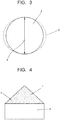
- FIG. 3 is a schematic view for explaining the sphericity.
- FIG. 3 illustrates the metal particle 2 with high sphericity, a virtual circle 4, and a maximum diameter 5.
- the sphericity is determined by using a macrophotograph.
- the macrophotograph is a photograph of a scanning electron microscope (SEM) at 100 magnifications or more and 1000 magnifications or less.
- a contour of the metal particle 2 with high sphericity is photographed in a circular shape in the SEM photograph. This shows that the metal particle 3 is seen with the shape closer to the perfect circle as the sphericity is higher.
- the external appearance of the metal particle 3 is seen as a sphere.
- the metal particle 3 with low sphericity is seen to have an angular surface in the SEM photograph. This shows that the metal particle 3 with low sphericity is seen to have a polygonal contour.
- the metal particles preferably include at least one metal particle having the sphericity of 90% or more.
- the metal powder for 3D printer includes metal particles 2 with high sphericity of 90% or more and metal particles 3 with low sphericity of less than 90%.
- the metal particles with the sphericity of 90% or more improve the flowability of the metal powder.
- a supply amount of the metal powder during the shaping through the 3D printing can be controlled constant.
- An upper limit of the sphericity is 100%.
- the contour may be angular as long as the sphericity is 90% or more.
- the contour of the metal particle 2 with high sphericity preferably has a circular shape. The metal particles with high sphericity are difficult to become an agglomerate.
- At least one metal particle being a primary particle and having a maximum diameter of 1 ⁇ m or more preferably has an aspect ratio within a range of 1.0 or more and 1.5 or less.
- the primary particle indicates a particle which does not agglomerate.
- the metal particle being the primary particle and having the maximum diameter of 1 ⁇ m or more indicates at least one metal particle which does not agglomerate and which has a maximum diameter of 1 ⁇ m or more.
- Such a metal particle preferably has the aspect ratio within the range of 1.0 or more and 1.5 or less. Control of the aspect ratio of the metal particle whose maximum diameter is large to be 1 ⁇ m or more, to 1.5 or less, reduces a gap formed around large metal particles. Since it is possible to achieve a structure in which small metal particles enter this gap, the shaping property is improved.
- a measuring method of the aspect ratio uses the SEM photograph, which is used when determining the sphericity.
- a maximum diameter of the primary particle photographed in the SEM photograph is set to a long diameter.
- a length of the metal particle in a direction perpendicular to the long diameter from a center of the long diameter is set to a short diameter.
- the long diameter / the short diameter is set to the aspect ratio. This operation is performed with respect to 50 particles, and an average value thereof is set to an average aspect ratio.
- a mass ratio of metal particles each having the maximum diameter of 1 ⁇ m or more and the sphericity of 90% or more is preferably within a range of 0.5 g or more per 10 g of the metal particles. Mixture of 0.5 g or more of metal particles with high sphericity per 10 g of the metal particles, improves their flowability. If the mass ratio is less than 0.5 g per 10 g of the metal particles, the effect of improving the flowability is small.
- An average particle diameter D 90 is preferably 60 ⁇ m or less. Even when the sphericity is high, if the particle diameter is excessively large, there is a possibility that a gap around large metal particles becomes large, and the shaping property is reduced.
- An upper limit of the proportion of the metal particles each having the maximum diameter of 1 ⁇ m or more and the sphericity of 90% or more is preferably 5 g or less per 10 g. It is also possible that the metal powder is formed only of the metal particles each having the maximum diameter of 1 ⁇ m or more and the sphericity of 90% or more. On the other hand, if the number of spherical metal particles is excessively large, a gap between the metal particles may become large.
- the mass ratio of the metal particles each having the maximum diameter of 1 ⁇ m or more and 60 ⁇ m or less and the sphericity of 90% or more and 100% or less is preferably within a range of 0.5 g or more and 5 g or less per 10 g.
- the increase in the mass ratio of the metal particles with high sphericity leads to an increase in cost.
- Method examples of adjusting the mass ratio of the metal particles each having the maximum diameter of 1 ⁇ m or more and the sphericity of 90% or more include a method in which a metal powder including metal particles with high sphericity and a metal powder including metal particles with low sphericity are separately produced, and then mixed.
- a method of arbitrarily extracting a metal powder of 10 g and performing SEM observation is also effective.
- SEM observation an area ratio between the powder with high sphericity and the powder with low sphericity is determined. The area ratio can be converted into a mass ratio by being multiplied by a specific gravity of the metal particle.
- a ratio of a bulk density to a true density is preferably 15% or more.
- the ratio of the bulk density to the true density is also referred to as a relative density.
- the relative density can express a filling density of the metal powder. The relative density is determined by an equation: (bulk density / true density) ⁇ 100 (%).
- the true density is a value obtained by dividing a volume of a metal powder itself after pores on a surface or inside thereof are removed, by a mass of the metal powder.
- the true density becomes the same as the specific gravity.
- the true density of tungsten is 19.3 g/cm 3
- the true density of molybdenum is 10.2 g/cm 3
- the true density of rhenium is 21.0 g/cm 3
- the true density of niobium is 8.6 g/cm 3
- the true density of tantalum is 16.7 g/cm 3 .
- the true density of an alloy can also be calculated from the specific gravity of each of components.
- the bulk density is a density measured by putting a metal powder into a measuring container, in which a gap in the measuring container is also regarded as a volume.
- the bulk density is also referred to as an apparent density.
- a density measured by further filling the metal powder in a gap formed by applying vibration to the measuring container containing the metal powder, is referred to as a tap density.
- the tap density is also one kind of the bulk density.
- the apparent density is employed as the bulk density.
- the apparent density is measured based on ASTM-B329-98 (Apparent Density of Metal Powder and Compounds Using the Scott Volumeter) being one of standards of American Society for Testing and Materials (ASTM). Further, as the measuring container in which the metal powder is put, a container with a diameter of 28 mm and a height of 20 mm is used.
- the relative density is 15% or more, this means that the metal powder for 3D printer has a predetermined filling density without being subjected to application of vibration.
- the metal powder has the predetermined filling density, it is possible to stabilize the existing proportion of the metal powder in the 3D printing.
- an upper limit of the relative density is not particularly limited, it is preferably 80% or less. When the relative density exceeds 80%, the density is excessively high, which may reduce the flowability.
- the relative density is preferably 15% or more and 80% or less, and more preferably 30% or more and 80% or less.
- the metal powder for 3D printer as described above is excellent in the flowability and the shaping property. Consequently, the metal powder for 3D printer is suitable for shaping a shaped article with the use of the 3D printing.
- the flowability can be evaluated by measuring a repose angle.
- the repose angle is preferably 65 degrees or less.
- the repose angle is measured by using a Scott volumeter according to TMIAS0101 (powder property test method: 2010).
- An example of the Scott volumeter is illustrated in FIG. 4 .
- the TMIAS0101 is an industry standard issued by Japan Tungsten & Molybdenum Industries Association.
- As the Scott volumeter it is also possible to use a volumeter based on ASTM-B329-98 described above.
- FIG. 4 is a schematic view for explaining the repose angle.
- FIG. 4 illustrates a metal powder 1 for 3D printer, a cup 6, and a repose angle 7.
- the repose angle 7 is measured by using the Scott volumeter.
- the metal powder 1 for 3D printer is poured into a large funnel of the Scott volumeter.
- the metal powder 1 for 3D printer is poured until when it fills the cup 6 and overflows to the periphery of the cup 6.
- the repose angle 7 made by an upper surface of the cup and each of both ends of a pile of the metal powder 1 for 3D printer is measured, and an average angle thereof is set to a repose angle.
- the metal powder 1 for 3D printer does not fall naturally to the cup 6, the metal powder on a wire mesh is lightly stirred with a brush to be poured into the cup 6.
- the cup 6 is a cup with a diameter of 28 mm and a height of 20 mm.
- the samples when measuring the repose angle the same sample may be used, or respectively new samples may also be used.
- the repose angle of 65 degrees or less indicates good flowability. When the flowability is good, it is possible to uniformly supply the powder onto a stage of the 3D printer. For this reason, the repose angle is preferably 65 degrees or less, and more preferably 60 degrees or less. The repose angle is still more preferably 50 degrees or less.
- a variation in the repose angle is preferably 5 degrees or less.
- the variation in the repose angle is determined by
- 3 degrees, or
- 3 degrees.
- a lower limit value of the repose angle is not particularly limited, it is 30 degrees or more.
- the repose angle is smaller than 30 degrees, the flowability becomes excessively high, resulting in that the variation in the repose angle is likely to be increased.
- the method for manufacturing the metal powder for 3D printer according to the embodiment is not particularly limited as long as the metal powder has the aforementioned configuration, but, as a method of obtaining the metal powder with good yield, the following method can be cited.
- the metal powder preferably contains, as its major constituent, at least one element selected from the group consisting of tungsten, molybdenum, rhenium, niobium, tantalum, chromium, and vanadium.
- the particle size D 90 is adjusted.
- the particle size D 10 is adjusted at intervals of 10 ⁇ m or more and 50 ⁇ m or less. It is also possible to cite a method in which metal particles within the predetermined particle size range are mixed, to thereby control the particle size distribution and the like.
- For controlling the particle size distribution there is also a method of utilizing airflow classification. It is also possible to combine both the method using the sieves and the airflow classification.
- the method it is preferable to employ the method in which the metal powders whose particle sizes are adjusted at intervals of 10 ⁇ m or more and 50 ⁇ m or less are mixed, to thereby control the particle size distribution.
- agglomerate powder By grinding the agglomerate powder, it becomes easy to control the particle size distribution based on the particle diameter of the primary particle.
- the grinder include a ball mill, a rod mill, a Semi-Autogenous Grinding (SAG) mill, and a jet mill.
- the metal powder with the sphericity of 90% or more is prepared, and a required amount thereof is added. It is also possible that the metal powder for 3D printer is formed only of the metal powder with the sphericity of 90% or more. A method in which the metal powder with the sphericity of 90% or more is classified, and a required amount thereof is added, is also effective.
- Method examples for manufacturing the metal powder with the sphericity of 90% or more include atomization processing, grinding processing, and granulation processing.
- the atomization processing is a method in which molten metal is jetted from a hole, and a flowed-out molten metal flow is blown by a high-pressure water or gas, to be scattered and solidified. Since the melted metal is solidified while being scattered, it is possible to produce a metal particle having a smooth surface and high sphericity.
- Examples of the atomization processing include a method in which metal particles are jetted, and are melted and solidified through high-frequency heating.
- Examples of the atomization processing include a gas atomization method, a water atomization method, and a centrifugal atomization method.
- Examples of the grinding processing include a method of grinding a metal ingot.
- the method of grinding the metal ingot is a method of performing grinding by using a grinder such as a ball mill.
- a grinder such as a ball mill.
- the grinding processing using the grinder forms a powder which is rounded and thus has high sphericity.
- the grinding processing using the grinder also has an effect of grinding the agglomerate powder.
- the grinding processing also effectively use a rotating electrode process (REP).
- a rotating electrode is melted by high-temperature plasma, and scattered as liquid drops by centrifugal force.
- the rotating electrode process is a method in which the liquid drops are ground by gas jet to be finely powdered.
- Method examples of increasing the sphericity include a method of using the granulation processing.
- the granulation processing is processing in which fine powders are solidified into a spherical shape.
- Examples of the processing include a method in which the metal powder is mixed with a resin binder to be turned into a spherical shape.
- examples of the processing include a method of using a low melting point metal as a binder.
- Examples of the low melting point metal preferably has a melting point of 1500°C or less. Examples of such metal include copper (whose melting point is 1085°C), aluminum (whose melting point is 660°C), and nickel (whose melting point is 1455°C).
- the granulated powder uses the binder. For this reason, the granulated powder can be distinguished from a simple agglomerate powder.
- the metal powder for 3D printer in which the particle size distribution has the maximum peak within the range of the particle diameters of 1 ⁇ m to 200 ⁇ m, and D 90 - D 10 is 10 ⁇ m or more.
- a use of the 3D printing using the metal powder for 3D printer of the embodiment enables to manufacture a shaped article having a molding made from the metal powder.
- the shaped article can be applied to one having various structures. Examples of the structure include a fin structure, a lattice structure, a plate structure, a bar structure, a column structure, a honeycomb structure, a hollow structure, and a spring structure.
- the metal powder of the embodiment even if the metal powder is the high melting point metal, it is possible to achieve the 3D printing excellent in the flowability and the shaping property.
- the high melting point metal is a material that is difficult to be sintered, so that by heating a molding at a high temperature, a sintered compact is formed.
- the sintered compact is subjected to cutting or the like to form a complicated shape, so that formation thereof is difficult.
- the shaped article according to the embodiment can be shaped using the 3D printing, so that the shaped article can be easily formed in a complicated shape.
- Examples of the 3D printing include a method of using laser beam or electron beam.
- the 3D printing using laser beam is called selective laser sintering (SLS).
- Examples of the selective laser sintering include direct metal laser sintering (DMLS).
- the SLS is a method in which a powder material is laid tightly on a shaping stage and is irradiated with laser beam. The irradiation of laser beam melts the powder material, and when it is cooled thereafter, the shaping is performed.
- the SLS is a method in which a process of newly supplying the powder material and performing the laser beam irradiation after the shaping, is repeatedly performed.
- the DMLS is the selective laser sintering with increased laser output power.
- the SLS uses carbon dioxide gas laser.
- the DMLS uses ytterbium laser.
- the SLS and the DMLS are methods of sintering the powder material using the laser beam.
- a method of using the laser beam there can also be cited selective laser melting (SLM).
- SLM is a method in which the powder material is melted by laser beam irradiation, to thereby perform shaping.
- the 3D printing using the electron beam is called electron beam melting (EBM).
- the electron beam is a beam of irradiating electrons emitted as a result of heating a filament in vacuum.
- the electron beam is characterized in that it has high output power and high speed when compared to the laser beam.
- the EBM is a technique in which a powder material is melted to be shaped.
- the EBM also includes a method of performing shaping by using a metal wire.
- the SLM or the EBM is a method of melting metal particles. The melting of metal particles makes it easier to obtain a shaped article with high density.
- the SLS (including the DMLS) preferably has laser output power of 100 W or more.
- the SLM preferably has laser output power of 100 W or more.
- the EBM preferably has output power of electron beam of 2000 W or more.
- the SLS, the SLM, or the EBM preferably has a shaping speed of 100 mm/s or more.
- the shaping speed is a speed of scanning laser beam or electron beam.
- the shaping speed is slow and mass productivity is reduced.
- an upper limit of the shaping speed is not particularly limited, it is preferably 5000 mm/s or less.
- the shaping speed is more than 5000 mm/s, a variation occurs in a sintered state or a molten state, resulting in that it becomes difficult to obtain a shaped article with high density.
- a step of laying a metal powder and solidifying the metal powder through laser beam irradiation is performed, and a step of laying the metal powder onto the solidified metal powder, and solidifying the metal powder through laser beam irradiation, is repeatedly performed.
- a relative density or an average density of the molding is preferably 90% or more.
- particle diameters of all metal particles are preferably set to be smaller than a thickness at which the metal powder is tightly laid.
- a method of tightly laying the metal powder to perform shaping through the 3D printing there is one called powder bed fusion.
- powder bed fusion a surface layer of the tightly-laid metal powder is flattened with a coater (a jig in a flat plate shape). If the particle diameters of the metal particles are larger than the thickness at which the metal powder is tightly laid, the metal particle is caught by the coater. Accordingly, a distribution state of the metal particles is changed by the caught portion. For this reason, the particle diameters of all metal particles are preferably set to be smaller than the thickness at which the metal powder is tightly laid.
- metal powders represented in Table 1 and Table 2 were prepared.
- tungsten powder of each of examples 1 to 8 and a comparative example 1 one having purity of 99 mass% or more was used.
- a molybdenum powder of each of examples 9 to 15 and a comparative example 2 one having purity of 99 mass% or more was used.
- a rhenium powder with purity of 99 mass% or more was used.
- a niobium powder with purity of 99 mass% or more was used.
- a tantalum powder with purity of 99 mass% or more was used.
- a hafnium carbide (HfC) powder of 0.7 mass% and a tungsten powder of 99.3 mass% were mixed.
- a titanium (Ti) powder of 0.5 mass% and a molybdenum powder of 99.5 mass% were mixed.
- Metal particles each having a maximum diameter of 1 ⁇ m or more and 30 ⁇ m or less and sphericity of 90% or more and 100% or less were prepared, and mixed so that a mass ratio of the metal particles each having the maximum diameter of 1 ⁇ m or more and the sphericity of 90% or more, per 10 g, satisfied values shown in Table 1 or Table 2.
- the adjustment of the particle size distribution was performed by a method of mixing previously-sieved metal particles.
- the metal particles with the sphericity of 90% or more and 100% or less, were manufactured by the atomization processing.
- the particle size distribution of each of the metal powders according to the examples and the comparative examples, was adjusted to fall within a range of particle diameters of 0.1 ⁇ m to 300 ⁇ m.
- FIG. 1 illustrates a particle size distribution of the metal powder according to the example 1.
- the flowability of the metal powder for 3D printer according to each of the examples and the comparative examples was examined.
- the flowability was evaluated by measuring the repose angle.
- the Scott volumeter was prepared, a sample was poured into a large funnel, and poured until when it filled a cup and overflowed to the periphery of the cup.
- the metal powder on a wire mesh was lightly stirred with a brush to be poured into the cup.
- an angle made by an upper surface of the cup and the powder was measured. This operation was performed five times by using arbitrarily extracted powders, an average value thereof was determined as the repose angle, and a variation was determined. The variation corresponds to a deviation angle relative to the average value of the repose angle.
- As the Scott volumeter one based on ASTM-B329-98 was used.
- the bulk density was also examined. As the measurement of the bulk density, the apparent density based on ASTMB-329-98 was measured. The measurement of the repose angle and the bulk density was performed by using a container with a diameter of 28 mm and a height of 20 mm. Based on this, a ratio between the bulk density and the true density (relative density) was determined by (bulk density / true density) ⁇ 100 (%). Results thereof are shown in Table 3.
- Example 1 Repose angle (degree) Relative density (%) Example 1 56 33.7 Example 2 49 17.7 Example 3 47 21.5 Example 4 44 32.4 Example 5 43.5 27.4 Example 6 35 44.2 Example 7 32 46.3 Example 8 31 56.8 Comparative example 1 75 13.5 Example 9 53 36.6 Example 10 55 19.1 Example 11 40 32.7 Example 12 48 47 Example 13 50 38.2 Example 14 32 47.8 Example 15 32 50.2 Comparative example 2 74 13.5 Example 16 55 25.9 Example 17 57 55.7 Example 18 60 43.3 Example 19 54 26.1 Example 20 53 28.6
- the molding has a fin structure or a hollow structure.
- the fin structure has five projections each having a height of 2 mm and a diameter of 2 mm, on a metal plate.
- the hollow structure has an outside diameter of 10 mm, an inside diameter of 8 mm, and a height of 5 mm.
- SLM type the 3D printing was performed at laser output power of 400 W and a shaping speed of 300 mm/s.
- the 3D printing was performed through powder bed fusion. In the powder bed fusion, particle diameters of metal particles were set to be smaller than a thickness of tightly-laid metal powder.
- the 3D printing was performed at electron beam output power of 3500 W and a shaping speed of 1000 mm/s.
- a density of each of the obtained shaped articles was measured. The density was measured based on the Archimedes method. Ten shaped articles were manufactured by using each of the metal powders for 3D printer. An average value of the densities of the ten shaped articles was set to an average density. A deviation relative to the average density was set to a density variation. Results thereof are shown in Table 4.
- the shaping property of the metal powder according to each of the examples was improved.
- the high density was obtained in either of the case where the shaping was performed by the SLM method and the case where the shaping was performed by the EBM method.
- the metal powder according to each of the examples is a powder suitable for the shaping through the 3D printer.
Landscapes
- Chemical & Material Sciences (AREA)
- Engineering & Computer Science (AREA)
- Materials Engineering (AREA)
- Manufacturing & Machinery (AREA)
- Nanotechnology (AREA)
- Mechanical Engineering (AREA)
- Metallurgy (AREA)
- Organic Chemistry (AREA)
- Physics & Mathematics (AREA)
- Plasma & Fusion (AREA)
- Powder Metallurgy (AREA)
Applications Claiming Priority (2)
| Application Number | Priority Date | Filing Date | Title |
|---|---|---|---|
| JP2018103587 | 2018-05-30 | ||
| PCT/JP2019/021319 WO2019230806A1 (ja) | 2018-05-30 | 2019-05-29 | 3dプリンタ用金属粉、造形物、および造形物の製造方法 |
Publications (2)
| Publication Number | Publication Date |
|---|---|
| EP3812064A1 true EP3812064A1 (de) | 2021-04-28 |
| EP3812064A4 EP3812064A4 (de) | 2022-02-09 |
Family
ID=68698237
Family Applications (1)
| Application Number | Title | Priority Date | Filing Date |
|---|---|---|---|
| EP19811569.3A Pending EP3812064A4 (de) | 2018-05-30 | 2019-05-29 | Metallpulver für 3d-drucker, formartikel und verfahren zur herstellung des formartikels |
Country Status (5)
| Country | Link |
|---|---|
| US (2) | US20210069781A1 (de) |
| EP (1) | EP3812064A4 (de) |
| JP (1) | JP7374892B2 (de) |
| CN (2) | CN116571762A (de) |
| WO (1) | WO2019230806A1 (de) |
Families Citing this family (7)
| Publication number | Priority date | Publication date | Assignee | Title |
|---|---|---|---|---|
| AT16308U3 (de) * | 2018-11-19 | 2019-12-15 | Plansee Se | Additiv gefertigtes Refraktärmetallbauteil, additives Fertigungsverfahren und Pulver |
| AT16307U3 (de) * | 2018-11-19 | 2019-12-15 | Plansee Se | Additiv gefertigtes Refraktärmetallbauteil, additives Fertigungsverfahren und Pulver |
| WO2022219981A1 (ja) * | 2021-04-13 | 2022-10-20 | 国立大学法人東北大学 | 磁歪材料の製造方法、磁歪材料およびエネルギー変換部材の製造方法 |
| CN114850490B (zh) * | 2022-03-31 | 2024-03-26 | 芯体素(杭州)科技发展有限公司 | 基于3d打印的电子散热器制作方法 |
| WO2023204032A1 (ja) * | 2022-04-20 | 2023-10-26 | 株式会社神戸製鋼所 | 水アトマイズ粉末及び積層造形方法 |
| CN115106540A (zh) * | 2022-07-26 | 2022-09-27 | 宁夏东方智造科技有限公司 | 钽钨合金制品及其制备方法 |
| CN117600494B (zh) * | 2024-01-24 | 2024-04-02 | 安庆瑞迈特科技有限公司 | 一种提高3d打印准直器耐腐蚀性和强度的打印方法 |
Family Cites Families (9)
| Publication number | Priority date | Publication date | Assignee | Title |
|---|---|---|---|---|
| JP2009270130A (ja) * | 2008-04-30 | 2009-11-19 | Aida Kagaku Kogyo Kk | 銀粉末または銀合金粉末、銀または銀合金の造形体の製造方法並びに銀または銀合金の造形体 |
| FR3008014B1 (fr) * | 2013-07-04 | 2023-06-09 | Association Pour La Rech Et Le Developpement De Methodes Et Processus Industriels Armines | Procede de fabrication additve de pieces par fusion ou frittage de particules de poudre(s) au moyen d un faisceau de haute energie avec des poudres adaptees au couple procede/materiau vise |
| JP5723942B2 (ja) | 2013-09-18 | 2015-05-27 | 株式会社不二機販 | 粉末状金属材料の表面処理方法 |
| JP6475478B2 (ja) * | 2014-11-27 | 2019-02-27 | 山陽特殊製鋼株式会社 | 造形用金属粉末 |
| DE102015004474B4 (de) * | 2015-04-08 | 2020-05-28 | Kai Klinder | Anlage zur Herstellung von Metallpulver mit definiertem Korngrößenspektrum |
| CN105478765B (zh) * | 2015-12-12 | 2017-05-24 | 北京工业大学 | 一种基于金属3d打印球形粉末的紧密堆积的配粉方法 |
| WO2017115648A1 (ja) * | 2015-12-28 | 2017-07-06 | Jx金属株式会社 | スパッタリングターゲットの製造方法 |
| EP3216545B2 (de) * | 2016-03-07 | 2022-09-28 | Heraeus Deutschland GmbH & Co. KG | Edelmetallpulver und dessen verwendung zur herstellung von bauteilen |
| CN106112000A (zh) * | 2016-08-29 | 2016-11-16 | 四川有色金源粉冶材料有限公司 | 一种3d打印金属粉末的制备方法 |
-
2019
- 2019-05-29 CN CN202310762316.3A patent/CN116571762A/zh active Pending
- 2019-05-29 EP EP19811569.3A patent/EP3812064A4/de active Pending
- 2019-05-29 CN CN201980035725.5A patent/CN112166004B/zh active Active
- 2019-05-29 JP JP2020522251A patent/JP7374892B2/ja active Active
- 2019-05-29 WO PCT/JP2019/021319 patent/WO2019230806A1/ja unknown
-
2020
- 2020-11-18 US US16/951,304 patent/US20210069781A1/en active Pending
-
2023
- 2023-11-14 US US18/508,389 patent/US20240082909A1/en active Pending
Also Published As
| Publication number | Publication date |
|---|---|
| CN112166004B (zh) | 2023-06-13 |
| EP3812064A4 (de) | 2022-02-09 |
| JPWO2019230806A1 (ja) | 2021-07-15 |
| CN112166004A (zh) | 2021-01-01 |
| CN116571762A (zh) | 2023-08-11 |
| WO2019230806A1 (ja) | 2019-12-05 |
| JP7374892B2 (ja) | 2023-11-07 |
| US20240082909A1 (en) | 2024-03-14 |
| US20210069781A1 (en) | 2021-03-11 |
Similar Documents
| Publication | Publication Date | Title |
|---|---|---|
| US20240082909A1 (en) | Metal powder for 3d printer, shaped article, and method for manufacturing shaped article | |
| EP3266541B1 (de) | Titanpulver | |
| JP6456992B2 (ja) | 貴金属粉末及び部品の製造のためのその使用 | |
| EP3392359A1 (de) | Legierungsteil mit hoher entropie, verfahren zur herstellung eines legierungselements und produkt unter verwendung des legierungselements | |
| EP3187285A1 (de) | Pulver zur schichtweisen generativen fertigung und verfahren zur herstellung eines objekts durch schichtweise generativen fertigung | |
| KR102419052B1 (ko) | 적층 제조 프로세스에서의 사용을 위한 분말 | |
| EP3738695A1 (de) | Edelstahlpulver zum formen | |
| EP3778068A1 (de) | Pulver für eine form | |
| US10858295B2 (en) | Composite particles, composite powder, method for manufacturing composite particles, and method for manufacturing composite member | |
| JP2019112700A (ja) | 金属粉末材料の製造方法 | |
| JP7404567B2 (ja) | 積層造形用粉砕粉 | |
| CN114641357A (zh) | 用于制造三维物体的球形粉末 | |
| KR102441218B1 (ko) | 탄화텅스텐 분말 | |
| WO2020230542A1 (ja) | 炭化タングステン粉末 | |
| KR102557249B1 (ko) | 연자성 합금 분말, 압분 자심, 자성 부품 및 전자 기기 | |
| US20220062986A1 (en) | Magnetic core, magnetic component and electronic device | |
| JP7249811B2 (ja) | 金属粉末材料の製造方法 | |
| WO2020218332A1 (ja) | 軟磁性合金粉末、圧粉磁心、磁性部品および電子機器 | |
| CN116786843A (zh) | 难熔金属构件及其制备方法 |
Legal Events
| Date | Code | Title | Description |
|---|---|---|---|
| STAA | Information on the status of an ep patent application or granted ep patent |
Free format text: STATUS: THE INTERNATIONAL PUBLICATION HAS BEEN MADE |
|
| STAA | Information on the status of an ep patent application or granted ep patent |
Free format text: STATUS: THE INTERNATIONAL PUBLICATION HAS BEEN MADE |
|
| PUAI | Public reference made under article 153(3) epc to a published international application that has entered the european phase |
Free format text: ORIGINAL CODE: 0009012 |
|
| STAA | Information on the status of an ep patent application or granted ep patent |
Free format text: STATUS: REQUEST FOR EXAMINATION WAS MADE |
|
| 17P | Request for examination filed |
Effective date: 20201130 |
|
| AK | Designated contracting states |
Kind code of ref document: A1 Designated state(s): AL AT BE BG CH CY CZ DE DK EE ES FI FR GB GR HR HU IE IS IT LI LT LU LV MC MK MT NL NO PL PT RO RS SE SI SK SM TR |
|
| AX | Request for extension of the european patent |
Extension state: BA ME |
|
| DAV | Request for validation of the european patent (deleted) | ||
| DAX | Request for extension of the european patent (deleted) | ||
| A4 | Supplementary search report drawn up and despatched |
Effective date: 20220111 |
|
| RIC1 | Information provided on ipc code assigned before grant |
Ipc: B22F 9/08 20060101ALN20220104BHEP Ipc: B33Y 80/00 20150101ALI20220104BHEP Ipc: B22F 10/28 20210101ALI20220104BHEP Ipc: C22C 1/04 20060101ALI20220104BHEP Ipc: B33Y 70/00 20200101ALI20220104BHEP Ipc: B22F 10/36 20210101ALI20220104BHEP Ipc: B22F 1/00 20220101ALI20220104BHEP Ipc: B22F 3/105 20060101ALI20220104BHEP Ipc: B22F 3/16 20060101AFI20220104BHEP |