EP3808256B1 - Compliance-überwachungsmodul für einen inhalator - Google Patents
Compliance-überwachungsmodul für einen inhalator Download PDFInfo
- Publication number
- EP3808256B1 EP3808256B1 EP20211646.3A EP20211646A EP3808256B1 EP 3808256 B1 EP3808256 B1 EP 3808256B1 EP 20211646 A EP20211646 A EP 20211646A EP 3808256 B1 EP3808256 B1 EP 3808256B1
- Authority
- EP
- European Patent Office
- Prior art keywords
- inhaler
- sensor
- pressure sensor
- boot
- data
- Prior art date
- Legal status (The legal status is an assumption and is not a legal conclusion. Google has not performed a legal analysis and makes no representation as to the accuracy of the status listed.)
- Active
Links
- 238000012544 monitoring process Methods 0.000 title claims description 40
- 239000003814 drug Substances 0.000 claims description 39
- 229940079593 drug Drugs 0.000 claims description 24
- 229940112141 dry powder inhaler Drugs 0.000 claims description 13
- 239000002775 capsule Substances 0.000 claims description 11
- 238000009530 blood pressure measurement Methods 0.000 claims description 2
- 229940071648 metered dose inhaler Drugs 0.000 claims description 2
- 238000000034 method Methods 0.000 description 34
- 239000000872 buffer Substances 0.000 description 13
- 238000004891 communication Methods 0.000 description 12
- 239000000843 powder Substances 0.000 description 11
- 238000005259 measurement Methods 0.000 description 10
- 238000005516 engineering process Methods 0.000 description 9
- 210000004072 lung Anatomy 0.000 description 9
- 239000007788 liquid Substances 0.000 description 7
- 238000012545 processing Methods 0.000 description 7
- 239000000443 aerosol Substances 0.000 description 6
- 230000007613 environmental effect Effects 0.000 description 6
- 239000012530 fluid Substances 0.000 description 6
- 230000000694 effects Effects 0.000 description 5
- 239000007789 gas Substances 0.000 description 5
- 229910052751 metal Inorganic materials 0.000 description 5
- 239000002184 metal Substances 0.000 description 5
- 230000004048 modification Effects 0.000 description 5
- 238000012986 modification Methods 0.000 description 5
- 230000008569 process Effects 0.000 description 5
- 239000003380 propellant Substances 0.000 description 5
- 230000004044 response Effects 0.000 description 5
- 230000005355 Hall effect Effects 0.000 description 4
- 230000008859 change Effects 0.000 description 4
- 230000008878 coupling Effects 0.000 description 4
- 238000010168 coupling process Methods 0.000 description 4
- 238000005859 coupling reaction Methods 0.000 description 4
- 238000001514 detection method Methods 0.000 description 4
- 230000033001 locomotion Effects 0.000 description 4
- 230000007246 mechanism Effects 0.000 description 4
- 230000003287 optical effect Effects 0.000 description 4
- 208000006545 Chronic Obstructive Pulmonary Disease Diseases 0.000 description 3
- 238000013459 approach Methods 0.000 description 3
- 208000006673 asthma Diseases 0.000 description 3
- 238000013461 design Methods 0.000 description 3
- 238000012377 drug delivery Methods 0.000 description 3
- 238000009472 formulation Methods 0.000 description 3
- 238000011068 loading method Methods 0.000 description 3
- 239000000203 mixture Substances 0.000 description 3
- 238000000465 moulding Methods 0.000 description 3
- 230000029058 respiratory gaseous exchange Effects 0.000 description 3
- 230000002618 waking effect Effects 0.000 description 3
- 230000004913 activation Effects 0.000 description 2
- 230000001464 adherent effect Effects 0.000 description 2
- 230000008901 benefit Effects 0.000 description 2
- 230000005540 biological transmission Effects 0.000 description 2
- 238000004590 computer program Methods 0.000 description 2
- 238000011109 contamination Methods 0.000 description 2
- 230000001419 dependent effect Effects 0.000 description 2
- 239000000428 dust Substances 0.000 description 2
- 238000011067 equilibration Methods 0.000 description 2
- 230000006872 improvement Effects 0.000 description 2
- 239000002245 particle Substances 0.000 description 2
- 230000037452 priming Effects 0.000 description 2
- 230000000241 respiratory effect Effects 0.000 description 2
- 208000023504 respiratory system disease Diseases 0.000 description 2
- 238000007789 sealing Methods 0.000 description 2
- 230000035945 sensitivity Effects 0.000 description 2
- 238000003860 storage Methods 0.000 description 2
- 238000012546 transfer Methods 0.000 description 2
- 238000009423 ventilation Methods 0.000 description 2
- 206010014561 Emphysema Diseases 0.000 description 1
- 208000005279 Status Asthmaticus Diseases 0.000 description 1
- 241001441724 Tetraodontidae Species 0.000 description 1
- 230000002159 abnormal effect Effects 0.000 description 1
- 238000004220 aggregation Methods 0.000 description 1
- 239000004411 aluminium Substances 0.000 description 1
- 229910052782 aluminium Inorganic materials 0.000 description 1
- XAGFODPZIPBFFR-UHFFFAOYSA-N aluminium Chemical compound [Al] XAGFODPZIPBFFR-UHFFFAOYSA-N 0.000 description 1
- 238000004458 analytical method Methods 0.000 description 1
- QVGXLLKOCUKJST-UHFFFAOYSA-N atomic oxygen Chemical compound [O] QVGXLLKOCUKJST-UHFFFAOYSA-N 0.000 description 1
- 230000001580 bacterial effect Effects 0.000 description 1
- 230000000903 blocking effect Effects 0.000 description 1
- 206010006451 bronchitis Diseases 0.000 description 1
- 238000009833 condensation Methods 0.000 description 1
- 230000005494 condensation Effects 0.000 description 1
- 239000006071 cream Substances 0.000 description 1
- 230000001934 delay Effects 0.000 description 1
- 239000013583 drug formulation Substances 0.000 description 1
- 238000001704 evaporation Methods 0.000 description 1
- 230000008020 evaporation Effects 0.000 description 1
- 238000001914 filtration Methods 0.000 description 1
- 230000036541 health Effects 0.000 description 1
- 238000002955 isolation Methods 0.000 description 1
- 238000005304 joining Methods 0.000 description 1
- 230000004199 lung function Effects 0.000 description 1
- 238000004519 manufacturing process Methods 0.000 description 1
- 230000013011 mating Effects 0.000 description 1
- 238000000691 measurement method Methods 0.000 description 1
- 238000012806 monitoring device Methods 0.000 description 1
- 230000000414 obstructive effect Effects 0.000 description 1
- 239000001301 oxygen Substances 0.000 description 1
- 229910052760 oxygen Inorganic materials 0.000 description 1
- 239000000546 pharmaceutical excipient Substances 0.000 description 1
- 229920001296 polysiloxane Polymers 0.000 description 1
- 238000003825 pressing Methods 0.000 description 1
- 230000010349 pulsation Effects 0.000 description 1
- 238000005096 rolling process Methods 0.000 description 1
- 238000004062 sedimentation Methods 0.000 description 1
- 239000011540 sensing material Substances 0.000 description 1
- 230000003019 stabilising effect Effects 0.000 description 1
- 229910001220 stainless steel Inorganic materials 0.000 description 1
- 239000010935 stainless steel Substances 0.000 description 1
- 239000000126 substance Substances 0.000 description 1
- 238000012360 testing method Methods 0.000 description 1
- 210000003813 thumb Anatomy 0.000 description 1
- 230000001960 triggered effect Effects 0.000 description 1
- XLYOFNOQVPJJNP-UHFFFAOYSA-N water Substances O XLYOFNOQVPJJNP-UHFFFAOYSA-N 0.000 description 1
Images


Classifications
-
- A—HUMAN NECESSITIES
- A61—MEDICAL OR VETERINARY SCIENCE; HYGIENE
- A61B—DIAGNOSIS; SURGERY; IDENTIFICATION
- A61B5/00—Measuring for diagnostic purposes; Identification of persons
- A61B5/08—Detecting, measuring or recording devices for evaluating the respiratory organs
- A61B5/097—Devices for facilitating collection of breath or for directing breath into or through measuring devices
-
- A—HUMAN NECESSITIES
- A61—MEDICAL OR VETERINARY SCIENCE; HYGIENE
- A61B—DIAGNOSIS; SURGERY; IDENTIFICATION
- A61B5/00—Measuring for diagnostic purposes; Identification of persons
- A61B5/08—Detecting, measuring or recording devices for evaluating the respiratory organs
- A61B5/087—Measuring breath flow
-
- A—HUMAN NECESSITIES
- A61—MEDICAL OR VETERINARY SCIENCE; HYGIENE
- A61B—DIAGNOSIS; SURGERY; IDENTIFICATION
- A61B5/00—Measuring for diagnostic purposes; Identification of persons
- A61B5/48—Other medical applications
- A61B5/4833—Assessment of subject's compliance to treatment
-
- A—HUMAN NECESSITIES
- A61—MEDICAL OR VETERINARY SCIENCE; HYGIENE
- A61M—DEVICES FOR INTRODUCING MEDIA INTO, OR ONTO, THE BODY; DEVICES FOR TRANSDUCING BODY MEDIA OR FOR TAKING MEDIA FROM THE BODY; DEVICES FOR PRODUCING OR ENDING SLEEP OR STUPOR
- A61M15/00—Inhalators
- A61M15/009—Inhalators using medicine packages with incorporated spraying means, e.g. aerosol cans
-
- A—HUMAN NECESSITIES
- A61—MEDICAL OR VETERINARY SCIENCE; HYGIENE
- A61M—DEVICES FOR INTRODUCING MEDIA INTO, OR ONTO, THE BODY; DEVICES FOR TRANSDUCING BODY MEDIA OR FOR TAKING MEDIA FROM THE BODY; DEVICES FOR PRODUCING OR ENDING SLEEP OR STUPOR
- A61M16/00—Devices for influencing the respiratory system of patients by gas treatment, e.g. mouth-to-mouth respiration; Tracheal tubes
- A61M16/0051—Devices for influencing the respiratory system of patients by gas treatment, e.g. mouth-to-mouth respiration; Tracheal tubes with alarm devices
-
- A—HUMAN NECESSITIES
- A61—MEDICAL OR VETERINARY SCIENCE; HYGIENE
- A61M—DEVICES FOR INTRODUCING MEDIA INTO, OR ONTO, THE BODY; DEVICES FOR TRANSDUCING BODY MEDIA OR FOR TAKING MEDIA FROM THE BODY; DEVICES FOR PRODUCING OR ENDING SLEEP OR STUPOR
- A61M16/00—Devices for influencing the respiratory system of patients by gas treatment, e.g. mouth-to-mouth respiration; Tracheal tubes
- A61M16/021—Devices for influencing the respiratory system of patients by gas treatment, e.g. mouth-to-mouth respiration; Tracheal tubes operated by electrical means
-
- G—PHYSICS
- G16—INFORMATION AND COMMUNICATION TECHNOLOGY [ICT] SPECIALLY ADAPTED FOR SPECIFIC APPLICATION FIELDS
- G16H—HEALTHCARE INFORMATICS, i.e. INFORMATION AND COMMUNICATION TECHNOLOGY [ICT] SPECIALLY ADAPTED FOR THE HANDLING OR PROCESSING OF MEDICAL OR HEALTHCARE DATA
- G16H20/00—ICT specially adapted for therapies or health-improving plans, e.g. for handling prescriptions, for steering therapy or for monitoring patient compliance
- G16H20/10—ICT specially adapted for therapies or health-improving plans, e.g. for handling prescriptions, for steering therapy or for monitoring patient compliance relating to drugs or medications, e.g. for ensuring correct administration to patients
-
- A—HUMAN NECESSITIES
- A61—MEDICAL OR VETERINARY SCIENCE; HYGIENE
- A61B—DIAGNOSIS; SURGERY; IDENTIFICATION
- A61B2562/00—Details of sensors; Constructional details of sensor housings or probes; Accessories for sensors
- A61B2562/02—Details of sensors specially adapted for in-vivo measurements
- A61B2562/028—Microscale sensors, e.g. electromechanical sensors [MEMS]
-
- A—HUMAN NECESSITIES
- A61—MEDICAL OR VETERINARY SCIENCE; HYGIENE
- A61B—DIAGNOSIS; SURGERY; IDENTIFICATION
- A61B2562/00—Details of sensors; Constructional details of sensor housings or probes; Accessories for sensors
- A61B2562/02—Details of sensors specially adapted for in-vivo measurements
- A61B2562/0285—Nanoscale sensors
-
- A—HUMAN NECESSITIES
- A61—MEDICAL OR VETERINARY SCIENCE; HYGIENE
- A61M—DEVICES FOR INTRODUCING MEDIA INTO, OR ONTO, THE BODY; DEVICES FOR TRANSDUCING BODY MEDIA OR FOR TAKING MEDIA FROM THE BODY; DEVICES FOR PRODUCING OR ENDING SLEEP OR STUPOR
- A61M15/00—Inhalators
-
- A—HUMAN NECESSITIES
- A61—MEDICAL OR VETERINARY SCIENCE; HYGIENE
- A61M—DEVICES FOR INTRODUCING MEDIA INTO, OR ONTO, THE BODY; DEVICES FOR TRANSDUCING BODY MEDIA OR FOR TAKING MEDIA FROM THE BODY; DEVICES FOR PRODUCING OR ENDING SLEEP OR STUPOR
- A61M15/00—Inhalators
- A61M15/0091—Inhalators mechanically breath-triggered
- A61M15/0096—Hindering inhalation before activation of the dispenser
-
- A—HUMAN NECESSITIES
- A61—MEDICAL OR VETERINARY SCIENCE; HYGIENE
- A61M—DEVICES FOR INTRODUCING MEDIA INTO, OR ONTO, THE BODY; DEVICES FOR TRANSDUCING BODY MEDIA OR FOR TAKING MEDIA FROM THE BODY; DEVICES FOR PRODUCING OR ENDING SLEEP OR STUPOR
- A61M16/00—Devices for influencing the respiratory system of patients by gas treatment, e.g. mouth-to-mouth respiration; Tracheal tubes
- A61M16/0057—Pumps therefor
- A61M16/0063—Compressors
-
- A—HUMAN NECESSITIES
- A61—MEDICAL OR VETERINARY SCIENCE; HYGIENE
- A61M—DEVICES FOR INTRODUCING MEDIA INTO, OR ONTO, THE BODY; DEVICES FOR TRANSDUCING BODY MEDIA OR FOR TAKING MEDIA FROM THE BODY; DEVICES FOR PRODUCING OR ENDING SLEEP OR STUPOR
- A61M16/00—Devices for influencing the respiratory system of patients by gas treatment, e.g. mouth-to-mouth respiration; Tracheal tubes
- A61M16/0003—Accessories therefor, e.g. sensors, vibrators, negative pressure
- A61M2016/0027—Accessories therefor, e.g. sensors, vibrators, negative pressure pressure meter
-
- A—HUMAN NECESSITIES
- A61—MEDICAL OR VETERINARY SCIENCE; HYGIENE
- A61M—DEVICES FOR INTRODUCING MEDIA INTO, OR ONTO, THE BODY; DEVICES FOR TRANSDUCING BODY MEDIA OR FOR TAKING MEDIA FROM THE BODY; DEVICES FOR PRODUCING OR ENDING SLEEP OR STUPOR
- A61M2205/00—General characteristics of the apparatus
- A61M2205/50—General characteristics of the apparatus with microprocessors or computers
-
- A—HUMAN NECESSITIES
- A61—MEDICAL OR VETERINARY SCIENCE; HYGIENE
- A61M—DEVICES FOR INTRODUCING MEDIA INTO, OR ONTO, THE BODY; DEVICES FOR TRANSDUCING BODY MEDIA OR FOR TAKING MEDIA FROM THE BODY; DEVICES FOR PRODUCING OR ENDING SLEEP OR STUPOR
- A61M2205/00—General characteristics of the apparatus
- A61M2205/82—Internal energy supply devices
- A61M2205/8206—Internal energy supply devices battery-operated
-
- A—HUMAN NECESSITIES
- A61—MEDICAL OR VETERINARY SCIENCE; HYGIENE
- A61M—DEVICES FOR INTRODUCING MEDIA INTO, OR ONTO, THE BODY; DEVICES FOR TRANSDUCING BODY MEDIA OR FOR TAKING MEDIA FROM THE BODY; DEVICES FOR PRODUCING OR ENDING SLEEP OR STUPOR
- A61M2209/00—Ancillary equipment
- A61M2209/08—Supports for equipment
- A61M2209/088—Supports for equipment on the body
Definitions
- the present disclosure generally relates to monitoring of patient compliance to medicament administration via an inhaler. More particularly, the disclosure relates to the use of a miniature pressure sensor for compliance monitoring in an inhaler.
- Inhalers or puffers are used for delivering medication into the body via the lungs. They can be used, for example, in the treatment of asthma and chronic obstructive pulmonary disease (COPD).
- Types of inhalers include metered dose inhalers (MDIs), nebulisers and dry powder inhalers (DPIs).
- MDIs comprise three major components: a canister, which is normally aluminium or stainless steel, where the drug formulation resides; a metering valve, which allows a metered quantity of the formulation to be dispensed with each actuation; and an actuator (or mouthpiece) which allows the patient to operate the device and directs aerosolised drug into the patient's lungs.
- the formulation itself is made up of the drug, a liquefied gas propellant and, in many cases, stabilising excipients.
- the actuator contains a mating discharge nozzle and generally includes a dust cap to prevent contamination. To use the inhaler the patient presses down on the top of the canister, with their thumb supporting the lower portion of the actuator.
- Actuation of the device releases a single metered dose of the formulation which contains the medication either dissolved or suspended in the propellant. Breakup of the volatile propellant into droplets, followed by rapid evaporation of these droplets, results in the generation of an aerosol consisting of micrometre-sized medication particles that are then inhaled.
- Jet nebulisers also known as atomisers, are connected by tubing to a compressor that causes compressed air or oxygen to flow at high velocity through a liquid medicine to turn it into an aerosol, which is then inhaled by the patient. Jet nebulisers are commonly used for patients in hospitals who have difficulty using other inhalers, such as in serious cases of respiratory disease, or severe asthma attacks.
- DPIs deliver medication to the lungs in the form of a dry powder.
- DPIs are commonly used to treat respiratory diseases such as asthma, bronchitis, emphysema and COPD.
- DPIs may require some procedure to allow a measured dose of powder to be ready for the patient to take.
- the medication is commonly held either in a capsule for manual loading or in a hopper/reservoir inside the inhaler. Once loaded or actuated, the patient puts the mouthpiece of the inhaler into their mouth and takes a deep inhalation, holding their breath for 5 to 10 seconds.
- Adherence deals with the patient following the prescription label, for example taking the prescribed number of doses per day. If the prescription calls for two doses each day, and the patient is taking two doses a day, they are considered 100% adherent. If the patient is only taking one dose a day, they are only 50% adherent. In the latter case, the patient is not getting the treatment prescribed by their doctor.
- Compliance relates to how the patient uses their drug delivery device. If used in the manner recommended for effective treatment, they are 100% compliant. If not used properly however, they are less than 100% compliant.
- Said requirement involves 1) inhaling and then, while continuing to inhale, 2) dispensing the medicament by pressing down on the canister, followed by 3) continued inhalation, and finally 4) holding of one's breath for a brief period of time.
- This last step is important for 'sedimentation' of drug to occur within the lungs.
- the flow rate during inhalation may need to exceed some minimum threshold value for the drug to be delivered effectively.
- compliance to such a multi-step process is not easy, either because they are not familiar with the procedure or, e.g. in the case of children and the elderly, find it difficult to perform.
- a dose counter may be triggered by the press of an actuation button or the opening of a cap or cover. While this provides patients, and caregivers, objective evidence that a device has been handled, it still fails to provide any kind of compliance information. There is no means of determining whether the user has inhaled the entire dose. As such, there is a need for a product that provides not only adherence information, but compliance information as well.
- a spirometer is an apparatus for measuring the volume of air inspired and expired by a patient's lungs. Spirometers measure ventilation, the movement of air into and out of the lungs. From the traces, known as spirograms, output by spirometers, it is possible to identify abnormal (obstructive or restrictive) ventilation patterns.
- Existing spirometers use a variety of different measurement methods including pressure transducers, ultrasonic and water gauge.
- a pressure sensor In order to monitor the flows associated with breathing, a pressure sensor is most convenient because pressure information can be used to determine flow, which can then be used to determine volume.
- Pressure sensors used for breath detection generally measure the pressure difference across a section of the patient airway. This is commonly done using two connections, by tubing or other suitable conduits, to connect the sensor to the airway. It is also possible to use a single connection to the airway, with the other port open to the atmosphere. A single port gauge type sensor can also be used if the pressure within the airway is measured both before and after flow is applied, the difference in readings representing the desired pressure drops across the air path resistance. However, the uncertainty associated with the first (no flow) reading is generally high.
- thermal drift Another problem with conventional pressure sensors is thermal drift; the phenomenon by which the pressure reading can change over time with changes in local temperature. It is possible to compensate for such drift using additional circuitry, but this adds cost and volume and increases power requirements.
- additional circuitry can be located within the pressure sensor itself, but considering that the sensor is generally somewhat removed from the gas being measured, the temperature detected may not be representative of that gas.
- the temperature monitoring circuitry could be located at the patient, but this adds additional components, plus cost and complexity.
- RF radio frequency
- Other potential sources include wireless communications devices, such as Wi-Fi routers and cordless phones, and various other forms of information technology (IT) equipment such as wirelessly networked printers.
- I information technology
- US6363842 discloses an inhaler having a body in the form of a boot, a mouthpiece, and an electronics components intended for improving medication compliance.
- the electronics components are arranged in a bottom portion of the body.
- a similar type of inhaler is disclosed in US5809997 , the electronics components being in a device for attachment to the rear side of the inhaler body.
- a further example of an inhaler having a compliance monitoring device is disclosed in US 2013/008436A1 .
- the invention provides an inhaler according to claim 1.
- Optional features of the invention are set out in the dependent claims.
- a compliance monitoring module for an inhaler comprising: a miniature pressure sensor, a sensor port of said sensor being configured to be pneumatically coupled to a flow channel of said inhaler through which a user can inhale; a processor configured to: receive data from a sensing element of the pressure sensor; receive data from a mode sensor configured to detect when the inhaler changes from an inactive mode to an active mode; and based on said data from said pressure sensor sensing element and said data from said mode sensor, compile a compliance report; and a transmitter configured to issue said compliance report.
- the miniature pressure sensor could be a microelectromechanical system (MEMS) pressure sensor or a nanoelectromechanical system (NEMS) pressure sensor.
- MEMS microelectromechanical system
- NEMS nanoelectromechanical system
- Said mode sensor could be an orientation sensor.
- Said mode sensor could be a means of determining that the inhaler has been primed for use.
- Said mode sensor could be one of: an accelerometer, a gyroscope, a mechanical switch, an optical sensor, a Hall effect sensor, a microphone, a temperature sensor and a further pressure sensor.
- said processor could be further configured to determine an orientation of said inhaler using said accelerometer or gyroscope.
- the processor could be further configured to determine that a compressor of the inhaler has activated based on data received from said accelerometer.
- said processor could be further configured to determine that a compressor of the inhaler has activated based on data received from said further pressure sensor.
- the mode sensor is an accelerometer and the inhaler is a dry powder inhaler (DPI) configured to receive dry powder medicament stored in capsules
- said processor could be further configured to determine that a capsule has been opened and/or vibrated/rotated within a chamber based on data received from said accelerometer.
- DPI dry powder inhaler
- the compliance monitoring module could be configured to be located entirely within the inhaler in use.
- the compliance monitoring module could be configured to be located at least partially external to the inhaler in use.
- the compliance monitoring module could further comprise a capillary tube configured for pneumatically coupling said sensor port to said flow channel.
- Said capillary tube could comprise a seal between the sensor port and the flow channel, said seal being configured to transfer pressure from the flow channel to the sensor port.
- the inhaler could be a pressurised metred dose inhaler (pMDI).
- pMDI pressurised metred dose inhaler
- Said flow channel could be a gap between an inhaler boot and a gas canister at least partially received therein.
- the compliance monitoring module could be configured to be mounted on a vertical outside edge of the inhaler that is uppermost in use.
- the compliance monitoring module could further comprise a lip for clipping the module to the inhaler, configured such that said pneumatic coupling is via a gap between said lip and an interior surface of an outermost wall of said inhaler boot.
- the inhaler could be a jet nebuliser.
- the compliance monitoring module could be configured to be mounted on an exterior surface of the inhaler that faces substantially away from a patient in use.
- the compliance monitoring module could comprise a user interface for indicating that dosing is complete.
- the processor could be further configured to determine, from said data from said pressure sensor sensing element, a level of liquid medicament remaining in the nebuliser.
- the inhaler could be a dry powder inhaler (DPI).
- DPI dry powder inhaler
- Said DPI could be configured to receive dry powder medicament stored in capsules.
- Said processor could be further configured to determine from said data received from the miniature pressure sensor whether one or more predetermined requirements for successful dosing are met.
- Said one or more requirements could comprise one or more of: flow rate exceeding a predetermined threshold value; inhalation duration exceeding a predetermined threshold value; flow rate exceeding a predetermined threshold value for at least a predetermined threshold duration; total volume inhaled exceeding a predetermined threshold value; and peak inspired flow (PIF) exceeding a predetermined threshold value.
- the module could be configured for use with an inhaler comprising means for user-actuated priming of a dosing mechanism.
- Said transmitter could be wireless.
- any two or more of the pressure sensor, processor and transmitter could be comprised in a single integrated circuit or System on Chip (SoC).
- SoC System on Chip
- the module could further comprise said flow channel, the pressure sensor being located inside the flow channel, the pressure sensor optionally being located in a recess in an internal wall of the flow channel.
- the module could further comprise said flow channel, the pressure sensor being located external to the flow channel and said sensor port being pneumatically coupled to the flow channel via an opening in a wall of the flow channel.
- the module could further comprise a seal arranged to pneumatically couple the sensor port to said opening, at least a part of said seal optionally being sandwiched between the pressure sensor and the wall, at least a part of said seal optionally extending from an exterior surface of said wall to a surface on which the pressure sensor is mounted so as to encapsulate the pressure sensor in a pneumatic chamber adjacent the wall.
- Said wall and said seal could be formed by a two-shot moulding process.
- the module could further comprise a thermally conductive gasket sandwiched between the pressure sensor and the wall, said thermally conductive gasket optionally acting as the seal.
- the module could further comprise an air-permeable, water-impermeable filter separating said sensor port from said flow channel.
- the pressure sensor could comprise a metal housing.
- the pressure sensor could be a MEMS barometric pressure sensor.
- the sensor could be a piezo-resistive or capacitive MEMS pressure sensor.
- Said processor could be comprised in the pressure sensor.
- the module could further comprise a data buffer configured to store data received from a sensing element of the pressure sensor.
- Said data buffer could optionally be comprised in the pressure sensor.
- Said data buffer could be configured to store data corresponding to one inhalation/exhalation waveform.
- Said data buffer could be a first in, first out (FIFO) data buffer.
- the module could further comprise an additional MEMS barometric pressure sensor configured for monitoring environmental barometric activity.
- the transmitter could be comprised in a transceiver configured to communicate data from and/or to the pressure sensor.
- the transmitter could be wireless.
- Said wireless transmitter could be a Bluetooth TM subsystem, optionally a Bluetooth TM Low Energy (BLE) integrated circuit or System on Chip (SoC).
- the pressure sensor and/or the transmitter could be mounted on a printed circuit board (PCB).
- PCB printed circuit board
- the module could further comprise a battery, optionally a coin cell, arranged to power the pressure sensor.
- the pressure sensor could have a sensitivity of 20 Pascals or less.
- the pressure sensor could comprise a sensing element.
- the processor could be configured to poll said sensing element at a frequency of greater than or equal to 100Hz.
- the module could further comprise control means for switching on the pressure sensor and/or waking the pressure sensor from a low power state.
- Said control means could be a mechanical switch, an optical sensor, an accelerometer or a Hall effect sensor.
- the processor could be configured to respond to said control means switching on and/or waking up the pressure sensor by taking a tare reading from said sensing element and calibrating data received from the sensing element subsequently using said tare reading.
- the processor could be configured to determine a dynamic zero from a moving average of measurements by the pressure sensor, and dynamically calibrate the pressure sensor according to said dynamic zero.
- the processor could be configured to filter out electrical noise inherent to the pressure sensor and/or environmental anomalies in data received from a sensing element of the pressure sensor.
- the module could further comprise a temperature sensor, optionally integral with the pressure sensor.
- the processor optionally comprised in one of the pressure and temperature sensors, could be configured to apply temperature compensation determined from data received from a sensing element of the temperature sensor to data received from a sensing element of the pressure sensor.
- the inhaler could further comprise a mouthpiece, said sensor port being pneumatically coupled to a flow channel in pneumatic communication with said mouthpiece.
- an inhaler accessory comprising the module of the first aspect, configured to be connected to an inhaler such that said sensor port is pneumatically coupled to a flow channel in pneumatic communication with a mouthpiece of said inhaler.
- an inhaler comprising the compliance monitoring module of the first aspect.
- a method for monitoring compliance of use of an inhaler comprising: receiving data from a mode sensor configured to detect when the inhaler changes from an inactive mode to an active mode; receiving data from a sensing element of a miniature pressure sensor, a sensor port of said sensor being configured to be pneumatically coupled to a flow channel of said inhaler through which a user can inhale; based on said data from said pressure sensor sensing element and said data from said mode sensor, compiling a compliance report; and issuing said compliance report.
- the miniature pressure sensor could be a microelectromechanical system (MEMS) pressure sensor or a nanoelectromechanical system (NEMS) pressure sensor.
- MEMS microelectromechanical system
- NEMS nanoelectromechanical system
- the pressure sensor could be a MEMS barometric pressure sensor.
- the sensor could be a piezo-resistive or capacitive MEMS pressure sensor.
- said method could further comprise determining, from said data from said pressure sensor sensing element, a level of liquid medicament remaining in the inhaler.
- the mode sensor is an accelerometer or a gyroscope
- said method could further comprise determining an orientation of said inhaler using said accelerometer or gyroscope.
- the mode sensor is an accelerometer or a further pressure sensor and the inhaler is a jet nebuliser, said method could further comprise determining that a compressor of the inhaler has activated using said accelerometer or further pressure sensor.
- the mode sensor is an accelerometer and the inhaler is a dry powder inhaler (DPI) configured to receive dry powder medicament stored in capsules
- said method could further comprise determining that a capsule has been opened and/or vibrated/rotated within a chamber using said accelerometer.
- DPI dry powder inhaler
- Said mode sensor could be an orientation sensor.
- Said mode sensor could be a means of determining that the inhaler has been primed for use.
- Said mode sensor could be one of: an accelerometer, a gyroscope, a mechanical switch, an optical sensor, a Hall effect sensor, a microphone, and a temperature sensor.
- the method could be performed entirely by the inhaler.
- the method could be performed at least partially by apparatus external to the inhaler.
- capillary tube configured for pneumatically coupling said sensor port to said flow channel.
- Said capillary tube could comprise a seal between the sensor port and the flow channel, said seal being configured to transfer pressure from the flow channel to the sensor port.
- the inhaler could be a pressurised metered dose inhaler (pMDI).
- pMDI pressurised metered dose inhaler
- Said flow channel could be a gap between an inhaler boot and a gas canister at least partially received therein.
- the method could be performed by a module mounted on a vertical outside edge of the inhaler that is uppermost in use.
- Said module could further comprise a lip for clipping the module to the inhaler, configured such that said pneumatic coupling is via a gap between said lip and an interior surface of an outermost wall of said inhaler boot.
- the inhaler could be a jet nebuliser.
- the method could be performed by a module mounted on an exterior surface of the inhaler that faces substantially away from a patient in use.
- the method could further comprise indicating, via a user interface, that dosing is complete.
- the method could further comprise determining, from said data from said pressure sensor sensing element, a level of liquid medicament remaining in the inhaler.
- the inhaler could be a dry powder inhaler (DPI).
- DPI dry powder inhaler
- Said DPI could be configured to receive dry powder medicament stored in capsules.
- Said method could further comprise determining from said data received from said pressure sensor whether one or more predetermined requirements for successful dosing are met.
- Said one or more requirements could comprise one or more of: flow rate exceeding a predetermined threshold value; inhalation duration exceeding a predetermined threshold value; flow rate exceeding a predetermined threshold value for at least a predetermined threshold duration; total volume inhaled exceeding a predetermined threshold value; and peak inspired flow (PIF) exceeding a predetermined threshold value.
- the inhaler could comprise means for user-actuated priming of a dosing mechanism.
- Said issuing could be by means of wireless transmission.
- any two or more of the pressure sensor, a processor and a transmitter for performing the method could be comprised in a single integrated circuit or System on Chip (SoC).
- SoC System on Chip
- the pressure sensor could be located inside the flow channel, the pressure sensor optionally being located in a recess in an internal wall of the flow channel.
- the pressure sensor could be located external to the flow channel and said sensor port could be pneumatically coupled to the flow channel via an opening in a wall of the flow channel.
- a seal could be arranged to pneumatically couple the sensor port to said opening, at least a part of said seal optionally being sandwiched between the pressure sensor and the wall, at least a part of said seal optionally extending from an exterior surface of said wall to a surface on which the pressure sensor is mounted so as to encapsulate the pressure sensor in a pneumatic chamber adjacent the wall.
- Said wall and said seal could be formed by a two-shot moulding process.
- thermally conductive gasket sandwiched between the pressure sensor and the wall, said thermally conductive gasket optionally acting as the seal.
- the pressure sensor could comprise a metal housing.
- the pressure sensor could be a MEMS barometric pressure sensor.
- the sensor could be a piezo-resistive or capacitive MEMS pressure sensor.
- a processor could be comprised in the pressure sensor.
- the method could further comprise storing data received from a sensing element of the sensor in a data buffer.
- Said data could correspond to one inhalation/exhalation waveform.
- Said data buffer could optionally be comprised in the pressure sensor.
- Said data buffer could be a first in, first out (FIFO) data buffer.
- the method could further comprise: monitoring environmental barometric activity using an additional MEMS barometric pressure sensor; and calibrating said sensor having the sensor port pneumatically coupled to said flow channel against said additional sensor.
- Said issuing could be by means of wireless transmission.
- Said wireless transmitting could use a Bluetooth TM protocol, optionally the Bluetooth TM Low Energy (BLE) protocol.
- BLE Bluetooth TM Low Energy
- the issuing could be by means of a transmitter comprised in a transceiver configured to communicate data from and/or to the pressure sensor.
- the transmitter could be wireless.
- Said wireless transmitter could be a Bluetooth TM subsystem, optionally a Bluetooth TM Low Energy (BLE) integrated circuit or System on Chip (SoC).
- the pressure sensor and/or the transmitter could be mounted on a printed circuit board (PCB).
- PCB printed circuit board
- the pressure sensor could be powered by a battery, optionally a coin cell.
- the pressure sensor could have a sensitivity of 20 Pascals or less.
- the pressure sensor could comprise a sensing element.
- the method could comprise polling said sensing element at a frequency of greater than or equal to 100Hz.
- the method could further comprise using control means to switch on the pressure sensor and/or wake the pressure sensor from a low power state.
- Said control means could be a mechanical switch, an optical sensor, an accelerometer or a Hall effect sensor.
- the method could further comprise, in response to said control means switching on and/or waking up the pressure sensor, taking a tare reading from said sensing element and calibrating data received from the sensing element subsequently using said tare reading.
- the method could further comprise determining a dynamic zero from a moving average of measurements by the pressure sensor, and dynamically calibrating the pressure sensor according to said dynamic zero.
- the method could further comprise filtering out electrical noise inherent to the pressure sensor and/or environmental anomalies in data received from a sensing element of the pressure sensor.
- the method could further comprise applying temperature compensation to data received from a sensing element of the pressure sensor using data received from a sensing element of a temperature sensor.
- the inhaler could further comprise a mouthpiece, said sensor port being pneumatically coupled to a flow channel in pneumatic communication with said mouthpiece.
- the method could further comprise determining the volume of air inspired or expired by a user of the inhaler from data sensed by a sensing element of the sensor.
- a computer program product comprising instructions for execution by a computer processor to perform the method of the fourth aspect.
- a compliance monitoring module substantially as herein described with reference to the accompanying figures.
- an inhaler accessory substantially as herein described with reference to the accompanying figures.
- an inhaler substantially as herein described with reference to the accompanying figures.
- Barometric pressure sensors are referenced to vacuum. They are sometimes referred to as altimeters since altitude can be deduced from barometric pressure readings. Sensors of this type have not generally been considered for use in breath detection because of their extremely wide range (20 to 110 kPa) and low resolution. Considering how a typical breath profile may generate pressure changes of the order of only 0.2 kPa, this would require operating the sensor over an extremely narrow portion of its operating range.
- a typical MEMS barometric sensor is capable of operation from 20 kPa to 110 kPa and can detect flow rates of less than 30 Ipm (litres per minute) when pneumatically coupled to a flow path having a known flow resistance.
- Using a barometric sensor enables use of the barometric pressure as a baseline throughout the measurement cycle, thereby addressing the uncertainty of other single port approaches.
- arometric pressure sensors are already in stressed condition, having an integral reference port sealed within the device under vacuum. This means that they have low hysteresis in the region of interest.
- MEMS sensors Due to the extremely small size and mass of their sensing elements, MEMS sensors are capable of reacting to extremely small pressure changes. Some are capable of resolving pressure changes as low as 1 Pa.
- MEMS pressure sensors can include all of the requisite analogue circuitry within the sensor package. Temperature compensation and/or digital interfaces can also be integrated with the pressure sensor.
- the Freescale MPL3115A2 MEMS barometer/altimeter chip (pressure sensor) is digital, using an I 2 C interface to communicate pressure information to a host micro-computer.
- MEMS pressure sensors can be packaged in metal. This provides RF shielding and good thermal conductivity for temperature compensation.
- MEMS pressure sensors are also low cost, exhibit low power consumption and are very small. This makes them especially suitable for use in portable and/or disposable devices which may, for example, be powered by batteries such as coin cells.
- MEMS pressure sensors makes it easy to incorporate them into existing designs of inhalers. It may be easier to incorporate them in or close to a mouthpiece to more accurately measure the pressure change caused by a patient's inhalation or exhalation.
- a miniature barometric pressure sensor can be connected directly to the patient airway using only a small hole to the air path which does not require tubing of any kind. This minimizes the possibility of moisture condensation and potential bacterial growth associated with elastomeric tubing.
- An internal seal for example a gel seal, can be included to protect the sensor element from contamination.
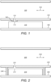
- FIG. 1 An example of this type of arrangement is shown in Figure 1 .
- a miniature barometric pressure sensor 110 is placed against the flow channel 120 through which a patient breathes. Airflow is substantially axial as indicated by arrow 130.
- the sensor port 111 is sealed in line with an opening 121 in flow channel wall 122 by a pneumatic (airtight) seal 140. (Note that, so long as there is a pneumatic connection between the sensor port and the flow channel, the seal need not be completely airtight.)
- Sensor port 111 optionally comprises a filter, for example an air-permeable, water-impermeable filter.
- the flow channel and the seal could be formed by a two-shot moulding process.
- the pressure sensor 110 can be mounted on a printed circuit board (PCB) 150 to provide connection to power sources and other electronics.
- PCB printed circuit board
- the entire miniature sensor could be encapsulated within a chamber adjacent to the flow channel as illustrated in Figure 2 .
- Pneumatic seal 240 is located outside of the sensor footprint and extends all the way from the exterior of flow channel wall 222 to the surface 250 on which the sensor 210 is mounted (for example the component surface of a PCB).
- Figure 2 shows a cross-section; pneumatic seal 240 surrounds the perimeter of the sensor 210 whether it is circular, square, rectangular or any other shape.
- the seal 240, sensor mount 250 and flow channel wall 222 thus form a cavity pneumatically isolated from the external environment except for the flow channel in the location of the opening 221.
- the pressure at the sensor port 211 is therefore equalised with the pressure in the flow channel at the opening 221.
- MEMS sensors are available with built-in temperature compensation, there may not be any need for use of external thermal sensors. Compensation can be provided right at the measurement site, increasing the accuracy of the compensation.
- a MEMS sensor with built-in temperature compensation can also act as a compact breath thermometer, providing further information to the patient and/or their caregiver. If the housing of the sensor is metal, then not only is the sensitive internal circuitry isolated from RF fields, such as those associated with mobile phones or nearby disturbances, but the sensor will also rapidly equilibrate to the local temperature in order to provide optimum temperature compensation.
- the miniature sensor is separated from the flow channel wall by an air gap.
- a thermally conductive gasket can be used as shown in Figure 3. ( Figure 3 is in other respects similar to Figure 2 .)
- a thermally conductive gasket 360 such as the silicone types used for transistor heat sinks, is provided between the (optionally metal) housing of the miniature sensor 310 and the flow channel wall 322.
- the gasket 360 could therefore extend over substantially the entire surface of the sensor 310 facing the flow channel wall 322.
- FIG. 4 shows an example arrangement in which a thermally conductive gasket 460 is made of an air-impermeable substance which deforms to the contours of the surfaces of the sensor 410 and flow channel wall 422 it is compressed between. It thus provides a good thermal connection while at the same time acting as a pneumatic seal, eliminating the need for a separate sealing element.
- An alternative to positioning the sensor adjacent the flow channel is to place the entire sensor within the low pressure airway of the device to be monitored as illustrated in Figure 5 .
- the sensor could be placed within the body of a DPI or the 'boot' of a pressurised MDI (pMDI).
- boot refers to the body of the inhaler that generally holds the drug canister.
- the sensor is truly measuring the pressure (and optionally, temperature) of the airflow itself, providing improved accuracy. Therefore there is also no need for any sealing element to create a pneumatic conduit between the flow channel 520 and the sensor port 511, or for any thermally conductive gasket to aid in temperature equilibration between them. It is also not necessary to provide the sensor with any access to the external pressure environment for reference purposes because the reference is already built into the sensor itself in the form of a vacuum reference.
- the miniature barometric pressure sensor 510 is mounted on the interior of flow channel wall 522, optionally via a PCB 550.
- the flow channel wall 522 may comprise a recessed part 523 in which the sensor 510 is located as shown to reduce disruption to the airflow indicated at 530.
- the depth of such a recess 523 could be substantially equal to the thickness of the sensor 510 so that the surface of the sensor comprising the sensor port 511 lies flush with the parts of the interior surface of flow channel wall 522 to either side of the sensor 510.
- Recess 523 could be a volume cut out of the wall 522 or a part of the wall that extends radially outwards relative to the rest as shown.
- miniature pressure sensors can be used to monitor patient flow through, for example, pMDIs, jet nebulisers or DPIs, thus facilitating low cost compliance monitoring, in addition to/in place of adherence monitoring, which confirms device actuation.
- Said compliance monitoring could be implemented using an accessory device that couples to the dosing device through a small hole to the airway to be monitored, through a capillary tube in fluid communication with the airway to be monitored, or in the dosing device itself.
- the small size, high performance and low cost of MEMS sensors make them ideally suited to such applications where size and weight are major considerations for users who may have to carry their inhaler with them at all times.
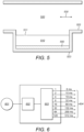
- FIG. 6 shows schematically some electronic components of an example MEMS barometric pressure sensor.
- Sensor element 601 passes analogue signals to analogue to digital converter (ADC) 602.
- ADC analogue to digital converter
- the digital output signal of ADC 602 is then averaged by a rolling average filter over many cycles to reduce noise.
- Various averages can be selected under program control in order to balance noise against response time.
- block 603 represents a means of selecting one of eight different oversample (i.e. filter) ratios to output at 604.
- the optimum setting can be chosen depending on the particular application. With an OSR setting of 16, the output is clean enough and the update time quick enough for most respiratory applications.
- the averaged output can then be passed to a circular first in, first out (FIFO) buffer (not shown) for storage until the data can be processed by a connected processor integrated into the device, or transmitted for offloaded processing.
- a FIFO buffer could, for example, store a number of samples approximately equivalent to, or a little greater than, one typical breath waveform to ensure that an entire inhalation/exhalation profile can be captured.
- Using a buffer reduces the demand on the serial port of the sensor in cases where the waveform is not required in real time.
- a user device such as a smart phone or tablet.
- data can optionally be communicated to a caregiver's device, for example a doctor's personal computer (PC).
- PC personal computer
- a wired connection for example via a Universal Serial Bus (USB) port.
- a wireless technology it is possible to communicate results to the outside world without interrupting the product housing in any significant way.
- Suitable wireless technologies could include, for example, WiFi technologies such as IEEE 802.11, Medical Body Area Network (MBAN) technologies such as IEEE 802.15, Near Field Communication (NFC) technologies, mobile technologies such as 3G and Bluetooth TM technologies such as Bluetooth TM Low Energy (BLE).
- a wireless transceiver for example in the form of a BLE chip, could be connected to the miniature pressure sensor or integrated with it.
- Such wireless connectivity could be used, for example, to report device actuation and/or sensed inhalation with date and time stamps in real time.
- This data could be processed externally and if the result of such processing is that it is determined that the patient is not fully compliant or that a prescription should be refilled, an alert can be sent to the patient and/or caregiver and/or pharmacist.
- Alerts could be provided via one or more user interfaces of the inhaler (for example an LED and/or a buzzer) or via text message or email.
- a reminder could be sent to the patient and/or caregiver. Alerts could also be generated for example if use frequency is exceeding a safe threshold.
- the compliance module could communicate directly or indirectly with one or more of: a user device (such as a mobile phone e.g. a smartphone, a tablet, a laptop or a desktop computer) of a patient, or of a caregiver (such as a doctor, nurse, pharmacist, family member or carer), a server e.g. of a health service provider or inhaler or drug manufacturer or distributor or a cloud storage system.
- a user device such as a mobile phone e.g. a smartphone, a tablet, a laptop or a desktop computer
- a caregiver such as a doctor, nurse, pharmacist, family member or carer
- a server e.g. of a health service provider or inhaler or drug manufacturer or distributor or a cloud storage system.
- Such communication could be via a network such as the Internet and may involve a dedicated app, for example on the patient's smartphone.
- Compliance monitoring means such as one or more sensors, e.g. a device actuation sensor such as a mechanical switch, an orientation sensor to check the device is in the proper orientation for efficient dosing such as an accelerometer or a gyroscope and a miniature pressure sensor to detect sufficient flow for proper dose delivery
- compliance reporting means such as a wireless transmitter or wired output port
- This module could be sold as a separate inhaler accessory/upgrade for attachment to an existing or slightly modified design of inhaler. Alternatively, the compliance monitoring module could be incorporated into the inhaler during manufacture.
- the compliance monitoring module it is not required for all components of the compliance monitoring module to be comprised in a single physical unit, though this may be the case (for example the electronic components could all be mounted on a single PCB or even incorporated into a single integrated circuit).
- the module could consist of one or more attachable units.
- the individual components could be located in any suitable locations in or on the inhaler and need not be grouped together or connected any further than required for them to function.
- the sensors may communicate with the processor and transmitter by wired or wireless means.
- the sensor port of the miniature pressure sensor may be directly pneumatically coupled to the flow channel by means of a vent or may be indirectly coupled by means of a capillary tube.
- a capillary tube a pressure-transferring seal could close the flow channel end of the tube to avoid drug and/or moisture entering the tube and damaging the pressure sensor, blocking the tube or affecting the hygiene of the device.
- the miniature pressure sensor could be located within the flow channel itself and communicate wirelessly with one or more of the other compliance module components located in or on another part of the inhaler. With the miniaturisation of electronic components, it may be possible to locate the entire compliance module within the flow channel without obstructing the flow.
- the compliance monitoring module could, for example, be used in the types of pMDIs described in US patent number 6,446,627 or US patent application publication number 13/110,532 .
- These inhalers comprise dose counters for monitoring adherence.
- a spooled ribbon marked with numerals to indicate the number of does remaining is driven to unwind by a ratchet wheel in turn driven by an actuator pawl actuated by movement of the canister.
- these inhalers do not comprise any means of determining whether the dose has been successfully administered.
- a miniature barometric pressure sensor anywhere in the airflow path through the inhaler or anywhere in fluid communication with the airflow path could enable compliance monitoring since such a miniature sensor could collect sufficient data to indicate whether or not the patient inhaled in an appropriate manner (e.g. hard enough and for long enough) to receive a full dose of medicament.
- This information combined with a signal originating from the dose counter mechanism is sufficient to confirm that a dose has been successfully administered.
- a signal could be obtained from the dose counter system in any convenient manner.
- an electronic switch could be arranged such that it is actuated by motion of the pawl or rotation of the spool. This switch could be connected to an input of the processor such that the processor receives an electronic pulse when a dose is metered. Since dose count will be available electronically, the ribbon could be omitted.
- Figures 7 to 10 illustrate further details of how a compliance module could be integrated into a pMDI.
- Figures 7 and 8 illustrate how compliance modules could be added to an existing pMDI without any modification, and could therefore be provided separately from the pMDI itself as an accessory/upgrade pack.
- Figures 9 to 10 illustrate how compliance modules could be integrated in pMDIs with some minor modifications.
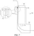
- Figure 7 illustrates an example in which a compliance module 710 is clipped on to a pMDI 700.
- pMDI 700 comprises a canister 720 received in a boot 730.
- a lip 711 of the compliance module hooks over the top of the boot wall in the radial gap between the boot wall and the canister.
- the compliance module is thereby clipped onto the inhaler without any modification to the inhaler.
- Arrow A shows the airflow when a user inhales through mouthpiece 740. Air passes down the radial gap between the canister and the boot, entrains aerosol sprayed from nozzle 721 on device actuation, and passes out into the user's mouth through mouthpiece 740.
- a MEMS pressure sensor 712 in the compliance module is pneumatically coupled to the flow channel formed by the radial gap between the boot and the canister by a capillary tube 713.
- the capillary tube follows the line of the external wall of the lip round into the gap but stops short of the bottom of the lip. This ensures that the lip blocks all air to the capillary tube except for that from below, i.e. within the boot.
- the lip could be shaped and positioned to provide sufficient fluid isolation such that no tube is needed.
- a compliance module 810 comprises an electronics unit 814 (including a MEMS pressure sensor) affixed to the underside of a cover 815. This all slips over the top of pMDI 800 surrounding the upper section of the boot 830 and the exposed part of the canister 820. With the compliance module in place and dust cap 850 removed, when a user inhales through mouthpiece 840 air flows in through the gap between cover 815 and boot 830, past electronics unit 814 including the MEMS pressure sensor, down the radial gap between the boot and canister, entrains aerosol sprayed from the canister nozzle on device actuation, and passes out into the user's mouth through mouthpiece 840.
- electronics unit 814 including the MEMS pressure sensor
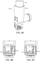
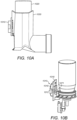
- FIG 9A is a partially exploded view of an example pMDI 900 comprising a compliance module 910 incorporated into the bottom of the boot 930.
- Figures 9B and 9C are interior views of the bottom part of the boot respectively before and during device activation.
- Compliance module 910 comprises MEMS pressure sensor 912, mechanical click dome switch 916 and processor (e.g. microcontroller unit, MCU) 917 mounted on PCB 918 and powered by coin cell battery 919. Before device actuation there is a gap above the upper click dome surface. During device activation the canister 920 is pushed down further into boot 930.
- a spring arm 960 affixed to the bottom of canister 920 consequently also moves down and pushes down on the upper surface of click dome 916, actuating the switch. This results in an actuation pulse signal being sent to the MCU.
- This signal can be used to determine patient adherence, while a signal sent from the pressure sensor to the MCU can be used to determine compliance.
- An accelerometer e.g. a three-axis accelerometer
- the accelerometer could also be used to sense the orientation of the inhaler during loading of a dose into the metering chamber to determine whether the inhaler is held upright as required for proper loading.
- the click dome switch could also act to connect the battery to the pressure sensor or, if no accelerometer is present, to the whole PCB. This would save battery power for only when it is needed.
- a thermistor could also be included on the PCB, providing further compliance data by indicating whether the temperature drop associated with completion of drug aerosolising occurs.
- the compliance module could alternatively be provided as a 'backpack' as shown in Figure 10 .
- Compliance module 1010 is affixed to the exterior of the boot 1030.
- a hole in boot 1030 provides fluid communication between the port of a MEMS pressure sensor 1012 and the flow channel formed in the radial gap between the boot 1030 and canister 1020.
- the sliding contact 1071 of a linear potentiometer 1070 is affixed to the canister such that it moves up and down with the canister. The contact 1071 slides in a slit in the boot 1030.
- the signal from the potentiometer indicates when the device is actuated and how long it is actuated for.
- the potentiometer could also act a switch to connect coin cell battery 1019 to PCB 1018 so that the PCB is only powered when the device is being actuated.
- the slit in which the contact 1071 slides could also provide fluid communication between the flow channel and the MEMS pressure sensor.
- Compliance monitoring modules could also be used in jet nebulisers.
- Figure 11 illustrates how this could be achieved.
- a compliance module 1110 comprising a MEMS pressure sensor 1112 is affixed to the exterior of a jet nebuliser 1100.
- the sensor port of the pressure sensor communicates with the interior of the nebuliser by means of a capillary tube 1113.
- the distal end of the tube extends down through a baffle 1120.
- Baffle 1120 is a flat plate which large aerosol droplets emitted by nozzle 1130 (powered by compressed air inlet 1131) reflect off of such that droplets exiting mouthpiece 1140 into the user's airway are of a uniform size. Locating the end of the capillary tube below the baffle prevents aerosol droplets from entering the tube; provided the nebuliser handset is not shaken so much that liquid medicament from reservoir 1150 splashes up into it, the interior of the tube should remain fairly dry.
- the pressure sensor effectively measures the pressure in the mouthpiece 1140.
- the airflow in the mouthpiece comprises a stream drawn in by user inhalation through vents indicated by arrow A, and a stream emitted by the nozzle.
- monitoring the pressure in the mouthpiece can provide both information about patient inhalation and information about the compressor, liquid drug level etc. This could enable feedback to the patient to indicate that treatment is complete or that the reservoir is empty.
- Patient adherence is often poor with jet nebulisers since the long treatment time (typically of the order of ten minutes) and high noise levels caused by the compressor and handset make it difficult for users to know when the treatment is complete.
- use of the compliance monitoring module could improve adherence.
- the pressure sensor could also be used to check pump function, and as a switch to wake up the rest of the compliance module when one of the large pulsations created by the pump is detected.
- An accelerometer could also be included in the compliance monitoring module. For full compliance, some jet nebulisers require the user to tap the handset to shake liquid droplets that have condensed in the mouthpiece back into the reservoir. An accelerometer could detect this tap. An accelerometer could also detect vibrations caused by the compressor to confirm that it is in use.
- Dry powder inhalers could also benefit from the addition of compliance monitoring modules.
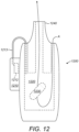
- An example DPI 1200 with a compliance monitoring module 1210 affixed thereto is shown in Figure 12 .
- Patient airflow is again shown by arrow A. It passes in through a vent in the inhaler body, passes through a dosing chamber 1220 comprising a medicament capsule 1230 (which has previously been pierced) and then passes out through mouthpiece 1240.
- the compliance module comprises a MEMS pressure sensor 1212 with a sensor port in fluid communication with the dosing chamber via a capillary tube 1213.
- An accelerometer or microphone could be included to detect structure-borne vibrations generated by movement of capsule 1230 within chamber 1220 during inhalation.
- a mechanical switch which feeds back compliance data to a compliance module processor could be actuated by a piercing or peeling mechanism (not shown) which primes the inhaler for use by opening the capsule 1230.
- MEMS barometric pressure sensors respond to environmental barometric pressure, which can change over time, attention should be paid to the initial reading that any subsequent sensor output signal analysis is based upon.
- An automatic zero reading i.e. tare
- a second barometer chip could be used to keep track of barometric activity, allowing the primary chip to be used exclusively for breath detection.
- the point at which dosing is complete i.e. where lung volume peaks
- the processor can make a determination that dosing is complete when the data from the pressure sensor indicates that flow direction has reversed.
- a wireless scheme (for example comprising a BLE module) could be used to transmit patient flow profiles to an app which could then calculate specific breathing parameters.
- the inhaler could thereby offload the processing required for such a task to, for example, a smart phone processor. This would facilitate the smallest form factors possible for the inhalers.
- a further advantage of this approach is that software running on a smart phone can be changed more readily than software running on an inhaler.
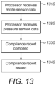
- FIG. 13 is a flowchart illustrating an example compliance monitoring method.
- a processor receives data from a mode sensor indicating that the inhaler has changed from being in an inactive mode to an active mode.
- the processor receives data from a sensing element of a miniature pressure sensor, a sensor port of said sensor being configured to be pneumatically coupled to a flow channel of said inhaler through which a user can inhale.
- the processor processes the data from the mode sensor and the pressure sensor in order to compile a compliance report.
- the processor passes the compliance report to a transmitter by which it is issued.
- Figures 14A and 14B show the mean pressures measured using a miniature relative pressure sensor affixed to the upper part of the casing of 10 different inhalers versus a series of air flow rates applied through the device. Repeat measurements were included for start, middle and end of life of each inhaler (in terms of progress through the number of "shots" before the doses run out).
- Figure 14A error bars are shown for a +/- 3 sigma variation.
- Figure 14B error bars are shown for a +/- 2 sigma variation, capturing a band that 95% of inhalers would fall into. We can thus get an idea of flow uncertainty for pressure measurements by such a sensor used in an inhaler.
- the uncertainty can be calculated from Figure 14A as ⁇ 16 l/min.
Claims (15)
- Inhalator, umfassend:einen Körper in Form eines Stiefels (830), eines Mundstücks (840) und einer Abdeckung (815) für einen oberen Abschnitt des Stiefels; undein Compliance-Überwachungsmodul (810), umfassend:einen Miniaturdrucksensor, wobei ein Sensoranschluss des Sensors konfiguriert ist, um pneumatisch mit einem Strömungskanal des Inhalators gekoppelt zu werden, durch den ein Benutzer inhalieren kann;einen Sender; undeinen Prozessor, der konfiguriert ist, um:Daten von einem Erfassungselement des Drucksensors zu empfangen,Daten von einem Modussensor zu empfangen, der konfiguriert ist, um zu erkennen, wann der Inhalator von einem inaktiven Modus in einen aktiven Modus wechselt; undeinen Compliance-Bericht basierend auf den Daten aus dem Drucksensor-Erfassungselement und den Daten aus dem Modussensor zu kompilieren, wobei der Sender konfiguriert ist, um den Compliance-Bericht auszugeben,wobei das Compliance-Überwachungsmodul (810) eine Elektronikeinheit (814) unter der Abdeckung (815) umfasst, wobei die Elektronikeinheit (814) den Miniaturdrucksensor enthält.
- Inhalator nach Anspruch 1, wobei die Elektronikeinheit (814) konfiguriert ist, um an einer Unterseite der Abdeckung (815) befestigt zu werden.
- Inhalator nach Anspruch 1 oder Anspruch 2, wobei der Inhalator ein unter Druck stehender Dosierinhalator ist.
- Inhalator nach Anspruch 3, wobei der Stiefel (830) konfiguriert ist, um einen Arzneimittelbehälter (820) zu halten, wobei zwischen dem Stiefel und dem Behälter ein Spalt vorgesehen ist, wenn der Behälter im Stiefel gehalten wird, wobei es ermöglicht wird, dass Luft durch den Spalt strömt, wenn der Benutzer durch das Mundstück (840) inhaliert.
- Inhalator nach Anspruch 4, wobei zwischen der Abdeckung (815) und dem Stiefel (830) ein Spalt so vorgesehen ist, dass es ermöglicht wird, dass Luft an der Elektronikeinheit (814) vorbeiströmt, wenn der Benutzer durch das Mundstück (840) inhaliert.
- Inhalator nach Anspruch 5, wobei das Compliance-Überwachungsmodul (810) an einer Unterseite der Abdeckung (815) befestigt ist und wobei die Abdeckung (815) konfiguriert ist, um den oberen Abschnitt des Stiefels (830) und einen freiliegenden Teil des Behälters (820) zu umgeben, wenn der Behälter im Stiefel gehalten wird.
- Inhalator nach einem der vorhergehenden Ansprüche, wobei der Miniaturdrucksensor ein Drucksensor eines mikroelektromechanischen Systems (MEMS) oder ein Drucksensor eines nanoelektromechanischen Systems (NEMS) ist.
- Inhalator nach einem der vorhergehenden Ansprüche, wobei der Prozessor konfiguriert ist, um: eine Tara-Druckanzeige basierend auf vom Miniaturdrucksensor empfangenen Daten zu bestimmen, bevor der Druckmesswert während der Inhalation basierend auf den Daten vom Miniaturdrucksensor bestimmt wird.
- Inhalator nach einem der vorhergehenden Ansprüche, wobei der Prozessor konfiguriert ist, um basierend auf den Daten vom Modussensor die Ausrichtung des Inhalators zu bestimmen oder um zu bestimmen, ob der Inhalator für die Verwendung vorbereitet worden ist.
- Inhalator nach einem der vorhergehenden Ansprüche, wobei der Prozessor ferner konfiguriert ist, um aus den vom Miniaturdrucksensor empfangenen Daten zu bestimmen, ob eine oder mehrere vorgegebene Anforderungen für eine erfolgreiche Dosierung erfüllt sind.
- Inhalator nach einem der vorhergehenden Ansprüche, wobei der Modussensor ein Mittel zum Bestimmen ist, dass der Inhalator für die Verwendung vorbereitet worden ist.
- Inhalator nach Anspruch 11, wobei der Modussensor ein mechanischer Schalter ist.
- Inhalator nach Anspruch 1, wobei der Inhalator ein Trockenpulverinhalator ist.
- Inhalator nach Anspruch 13, wobei der Modussensor ein Beschleunigungsmesser ist und wobei der
Prozessor konfiguriert ist, um zu bestimmen, dass der Inhalator für die Verwendung vorbereitet worden ist, wenn die Daten vom Modussensor darauf hinweisen, dass eine Medikamentenkapsel in einer Kammer des Inhalators geöffnet und/oder vibriert worden ist. - Inhalator nach einem der vorhergehenden Ansprüche, umfassend den Modussensor.
Applications Claiming Priority (3)
| Application Number | Priority Date | Filing Date | Title |
|---|---|---|---|
| US201462043114P | 2014-08-28 | 2014-08-28 | |
| PCT/US2015/047369 WO2016033421A1 (en) | 2014-08-28 | 2015-08-28 | Compliance monitoring module for an inhaler |
| EP15760031.3A EP3185752B1 (de) | 2014-08-28 | 2015-08-28 | Compliance-überwachungsmodul für einen inhalator |
Related Parent Applications (1)
| Application Number | Title | Priority Date | Filing Date |
|---|---|---|---|
| EP15760031.3A Division EP3185752B1 (de) | 2014-08-28 | 2015-08-28 | Compliance-überwachungsmodul für einen inhalator |
Publications (2)
| Publication Number | Publication Date |
|---|---|
| EP3808256A1 EP3808256A1 (de) | 2021-04-21 |
| EP3808256B1 true EP3808256B1 (de) | 2024-04-10 |
Family
ID=54064614
Family Applications (2)
| Application Number | Title | Priority Date | Filing Date |
|---|---|---|---|
| EP15760031.3A Revoked EP3185752B1 (de) | 2014-08-28 | 2015-08-28 | Compliance-überwachungsmodul für einen inhalator |
| EP20211646.3A Active EP3808256B1 (de) | 2014-08-28 | 2015-08-28 | Compliance-überwachungsmodul für einen inhalator |
Family Applications Before (1)
| Application Number | Title | Priority Date | Filing Date |
|---|---|---|---|
| EP15760031.3A Revoked EP3185752B1 (de) | 2014-08-28 | 2015-08-28 | Compliance-überwachungsmodul für einen inhalator |
Country Status (11)
| Country | Link |
|---|---|
| US (2) | US10905356B2 (de) |
| EP (2) | EP3185752B1 (de) |
| JP (3) | JP7000151B2 (de) |
| AR (1) | AR101720A1 (de) |
| CA (2) | CA3219518A1 (de) |
| ES (1) | ES2843262T3 (de) |
| IL (2) | IL250750B (de) |
| MA (1) | MA40507A (de) |
| MX (1) | MX2017002550A (de) |
| TW (1) | TW201620569A (de) |
| WO (1) | WO2016033421A1 (de) |
Families Citing this family (36)
| Publication number | Priority date | Publication date | Assignee | Title |
|---|---|---|---|---|
| ES2843262T3 (es) * | 2014-08-28 | 2021-07-16 | Norton Waterford Ltd | Módulo de monitorización del cumplimiento de un inhalador |
| EA037087B1 (ru) * | 2014-08-28 | 2021-02-04 | Нортон (Уотерфорд) Лимитед | Модуль для ингалятора, содействующий приверженности терапии |
| CA2968361A1 (en) * | 2014-11-20 | 2016-05-26 | Cognita Labs, LLC | Method and apparatus to measure, aid and correct the use of inhalers |
| GB2547279A (en) * | 2016-02-15 | 2017-08-16 | Univ Of Wales Trinity Saint David | Inhaler device |
| GB201605102D0 (en) | 2016-03-24 | 2016-05-11 | Nicoventures Holdings Ltd | Mechanical connector for electronic vapour provision system |
| US10894142B2 (en) | 2016-03-24 | 2021-01-19 | Trudell Medical International | Respiratory care system with electronic indicator |
| BR112018070608B1 (pt) | 2016-04-12 | 2022-05-03 | Biocorp Production S.A | Dispositivo complementar de observância do inalador dosimetrado e inalador dosimetrado |
| US10850050B2 (en) | 2016-05-19 | 2020-12-01 | Trudell Medical International | Smart valved holding chamber |
| CN114588435A (zh) | 2016-05-19 | 2022-06-07 | 曼金德公司 | 用于检测和监控吸入的装置、系统和方法 |
| CN116712646A (zh) * | 2016-05-27 | 2023-09-08 | 普罗沃锐斯科学有限公司 | 用于使用药剂装置的装置和方法 |
| EP3472567B1 (de) * | 2016-06-17 | 2020-04-22 | Thin Film Electronics ASA | Drahtloser mechanismus zur erkennung eines offenen oder geschlossenen behälters und verfahren zur herstellung und verwendung davon |
| CN109475295B (zh) * | 2016-06-29 | 2022-07-26 | 皇家飞利浦有限公司 | 用于健康设备和可穿戴/可植入设备的方法和设备 |
| EP3984579A1 (de) | 2016-07-08 | 2022-04-20 | Trudell Medical International | Intelligente schwingende vorrichtung für positiven ausatmungsdruck |
| KR102534558B1 (ko) | 2016-12-06 | 2023-05-19 | 노턴 (워터포드) 리미티드 | 통합된 전자 모듈을 가진 흡입 디바이스 |
| ES2886974T3 (es) * | 2016-12-09 | 2021-12-21 | Microdose Therapeutx Inc | Inhalador |
| ES2920151T3 (es) | 2016-12-09 | 2022-08-01 | Trudell Medical Int | Nebulizador inteligente |
| GB2565797B (en) * | 2017-08-22 | 2021-09-08 | Clement Clarke International Ltd | Device with flow rate indicator |
| EP3485930B1 (de) * | 2017-11-20 | 2021-04-14 | Presspart Gmbh & Co. Kg | Inhalationssystem |
| CA3086890A1 (en) | 2018-01-04 | 2019-07-11 | Trudell Medical International | Smart oscillating positive expiratory pressure device |
| FR3077496B1 (fr) * | 2018-02-06 | 2024-03-15 | Nemera La Verpilliere | Dispositif d’assistance a l’utilisation d’un dispositif de distribution a activation axiale |
| CA3132450A1 (en) * | 2018-03-05 | 2019-09-12 | Argospire Medical Inc. | Portable inhalation therapeutic and inhalation and exhalation measuring devices and related methods |
| US11071836B2 (en) | 2018-03-29 | 2021-07-27 | Reciprocal Labs Corporation | Single dose inhaler monitoring attachment |
| EP3801714A4 (de) | 2018-06-04 | 2022-03-09 | Trudell Medical International | Intelligente haltekammer mit ventil |
| WO2020051718A1 (en) * | 2018-09-14 | 2020-03-19 | Thorasys Thoracic Medical Systems Inc. | Self-use oscillometry device |
| WO2020065621A1 (en) | 2018-09-27 | 2020-04-02 | Breathesuite Inc. | Accessories for inhalers |
| EP3653247B1 (de) * | 2018-11-19 | 2021-03-31 | Sensirion AG | Bestimmung der luftdurchflussmenge durch einen inhalator |
| GB201821331D0 (en) * | 2018-12-31 | 2019-02-13 | 3M Innovative Properties Co | Inhaler detection |
| CN114423479A (zh) | 2019-06-17 | 2022-04-29 | 弗劳恩霍夫应用研究促进协会 | 用于确定气溶胶的给药速率的传感器模块和方法 |
| JP2022539267A (ja) * | 2019-07-05 | 2022-09-07 | ノートン (ウォーターフォード) リミテッド | 電子機器および電力管理を有する薬送達デバイス |
| USD946138S1 (en) | 2019-07-31 | 2022-03-15 | Reciprocal Labs Corporation | Modular inhaler adherence monitor |
| JP2022543111A (ja) * | 2019-07-31 | 2022-10-07 | レシプロカル ラボ コーポレイション | モジュール式吸入器の遵守モニタ |
| ES2807698B2 (es) * | 2019-08-23 | 2022-01-03 | Igncyerto S L | Dispositivo y metodo de medicion de dosis en inhaladores de polvo seco |
| CA3152072A1 (en) | 2019-08-27 | 2021-03-04 | Trudell Medical International | Smart oscillating positive expiratory pressure device |
| KR20220098000A (ko) * | 2019-11-13 | 2022-07-08 | 얀센 바이오테크 인코포레이티드 | 약물 전달 장치 감지 모듈 |
| BR112022006122A2 (pt) | 2019-11-18 | 2022-06-21 | Vectura Delivery Devices Ltd | Inalador de pó seco |
| EP4291273A1 (de) * | 2021-02-13 | 2023-12-20 | Norton (Waterford) Limited | Inhalatorsystem |
Family Cites Families (192)
| Publication number | Priority date | Publication date | Assignee | Title |
|---|---|---|---|---|
| US955201A (en) | 1909-11-10 | 1910-04-19 | Universal Winding Co | Variable-speed mechanism. |
| US4972842A (en) | 1988-06-09 | 1990-11-27 | Vital Signals, Inc. | Method and apparatus for precision monitoring of infants on assisted ventilation |
| US4984158A (en) | 1988-10-14 | 1991-01-08 | Hillsman Dean | Metered dose inhaler biofeedback training and evaluation system |
| US5071453A (en) * | 1989-09-28 | 1991-12-10 | Litton Systems, Inc. | Oxygen concentrator with pressure booster and oxygen concentration monitoring |
| US5363842A (en) * | 1991-12-20 | 1994-11-15 | Circadian, Inc. | Intelligent inhaler providing feedback to both patient and medical professional |
| FR2701399B1 (fr) * | 1993-02-16 | 1995-03-31 | Valois | Dispositif portatif de pulvérisation à actionnement déclenché par l'inhalation. |
| US5505192A (en) * | 1993-11-12 | 1996-04-09 | New-Med Corporation | Dispenser monitoring system |
| US6390088B1 (en) | 1993-12-13 | 2002-05-21 | Boehringer Ingelheim Kg | Aerosol inhaler |
| EP0667168B1 (de) | 1994-02-14 | 2000-06-21 | Aradigm Corporation | Inhalationsübungsgerät |
| SE9400570D0 (sv) | 1994-02-21 | 1994-02-21 | Astra Ab | Inhalation device, inhaler and processing unit |
| US5839429A (en) | 1994-03-25 | 1998-11-24 | Astra Aktiebolag | Method and apparatus in connection with an inhaler |
| SE9402237D0 (sv) | 1994-06-23 | 1994-06-23 | Astra Ab | Measurement methods and systems |
| GB9421687D0 (en) | 1994-10-27 | 1994-12-14 | Aid Medic Ltd | Dosimetric spacer |
| US5809997A (en) * | 1995-05-18 | 1998-09-22 | Medtrac Technologies, Inc. | Electronic medication chronolog device |
| AUPN332295A0 (en) | 1995-06-01 | 1995-06-29 | Butler, Donald Lewis | Personal pulmonary function analysers |
| US5957125A (en) | 1996-11-05 | 1999-09-28 | Medical Safety Products, Inc. | Apparatus for indicating proper orientation for oral and nasal inhalers |
| GB2320489A (en) | 1996-12-20 | 1998-06-24 | Norton Healthcare Ltd | Inhaler dose counter |
| SE9801122D0 (sv) | 1998-03-30 | 1998-03-30 | Astra Ab | Inhalation device |
| SE9801121D0 (sv) | 1998-03-30 | 1998-03-30 | Astra Ab | Electrical device |
| SE9801115D0 (sv) | 1998-03-30 | 1998-03-30 | Astra Ab | Electrical device |
| US6283923B1 (en) | 1998-05-28 | 2001-09-04 | The Trustees Of Columbia University In The City Of New York | System and method for remotely monitoring asthma severity |
| WO1999063901A1 (en) | 1998-06-08 | 1999-12-16 | Glaxo Group Limited | Disease management/training system and method |
| ES2253898T3 (es) | 1998-06-12 | 2006-06-01 | Microdose Technologies Inc. | Dispositivo para la administracion de farmacos y medicamentos. |
| AU5970899A (en) * | 1998-08-28 | 2000-03-21 | Glaxo Group Limited | Dispenser |
| HUP0104966A3 (en) | 1998-11-30 | 2004-12-28 | Novo Nordisk As | A medical system and a method of controlling the system for use by a patient for medical self treatment |
| AU3158600A (en) | 1999-03-06 | 2000-09-28 | Glaxo Group Limited | Medicament delivery system |
| GB9911388D0 (en) | 1999-05-18 | 1999-07-14 | Glaxo Group Ltd | Dispenser |
| US6288646B1 (en) | 1999-08-31 | 2001-09-11 | Air Advice.Com | Allergen detection and air/asthma advice provision |
| US20030192535A1 (en) | 1999-09-24 | 2003-10-16 | Astrazeneca Ab. | Inhaler |
| EP1224600B1 (de) | 1999-10-01 | 2007-06-13 | Glaxo Group Limited | System zum überwachen von patientendaten |
| AR026914A1 (es) | 1999-12-11 | 2003-03-05 | Glaxo Group Ltd | Distribuidor de medicamento |
| JP4777574B2 (ja) | 2000-02-11 | 2011-09-21 | レスピロニクス・レスピラトリー・ドラッグ・デリバリー・(ユーケー)・リミテッド | 薬剤投与装置 |
| GB0003839D0 (en) * | 2000-02-19 | 2000-04-05 | Glaxo Group Ltd | Housing for an inhaler |
| GB0004456D0 (en) | 2000-02-26 | 2000-04-19 | Glaxo Group Ltd | Medicament dispenser |
| JP2004503338A (ja) | 2000-07-15 | 2004-02-05 | グラクソ グループ リミテッド | 薬剤取り出し装置 |
| GB0021024D0 (en) | 2000-08-29 | 2000-10-11 | Glaxo Group Ltd | Inhalation device |
| GB0025749D0 (en) | 2000-10-20 | 2000-12-06 | Glaxo Group Ltd | Inhaler |
| GB0026646D0 (en) * | 2000-10-31 | 2000-12-13 | Glaxo Group Ltd | Medicament dispenser |
| GB0108228D0 (en) | 2001-04-02 | 2001-05-23 | Glaxo Group Ltd | Medicament dispenser |
| GB0108213D0 (en) | 2001-04-02 | 2001-05-23 | Glaxo Group Ltd | Medicament dispenser |
| GB0108208D0 (en) | 2001-04-02 | 2001-05-23 | Glaxo Group Ltd | Medicament dispenser |
| US20080177154A1 (en) | 2001-08-13 | 2008-07-24 | Novo Nordisk A/S | Portable Device and Method Of Communicating Medical Data Information |
| GB0127989D0 (en) * | 2001-11-22 | 2002-01-16 | Glaxo Group Ltd | Medicament dispensing system |
| GB0217199D0 (en) | 2002-07-25 | 2002-09-04 | Glaxo Group Ltd | Medicament dispenser |
| EP1471868A1 (de) | 2002-01-30 | 2004-11-03 | Glaxo Group Limited | Hilfsvorrichtung zur befolgung einer arzneimitteltherapie |
| GB0209531D0 (en) | 2002-04-26 | 2002-06-05 | Glaxo Group Ltd | Medicament dispenser |
| EP1499276A2 (de) | 2002-04-29 | 2005-01-26 | Glaxo Group Limited | Warnsystem |
| GB0209783D0 (en) | 2002-04-29 | 2002-06-05 | Glaxo Group Ltd | Medicament dispenser |
| GB0216831D0 (en) | 2002-07-19 | 2002-08-28 | Glaxo Group Ltd | Medicament dispenser |
| AU2003254590A1 (en) | 2002-07-25 | 2004-02-16 | Glaxo Group Limited | Medicament dispenser |
| GB0311461D0 (en) | 2003-05-19 | 2003-06-25 | Glaxo Group Ltd | Display system |
| US20050172958A1 (en) | 2003-08-20 | 2005-08-11 | The Brigham And Women's Hospital, Inc. | Inhalation device and system for the remote monitoring of drug administration |
| GB2406283B (en) | 2003-09-24 | 2006-04-05 | Altana Pharma Ag | Compliance monitor and method |
| GB2398065A (en) * | 2003-10-16 | 2004-08-11 | Bespak Plc | Dispensing apparatus |
| US20050108046A1 (en) | 2003-11-18 | 2005-05-19 | Boehringer Ingelheim Pharmaceuticals, Inc. | Clinical management system and methods |
| GB0328859D0 (en) * | 2003-12-12 | 2004-01-14 | Clinical Designs Ltd | Dispenser and counter |
| US8403865B2 (en) | 2004-02-05 | 2013-03-26 | Earlysense Ltd. | Prediction and monitoring of clinical episodes |
| US9131891B2 (en) | 2005-11-01 | 2015-09-15 | Earlysense Ltd. | Monitoring a condition of a subject |
| DE102004009435A1 (de) | 2004-02-24 | 2005-12-08 | Boehringer Ingelheim International Gmbh | Zerstäuber |
| US8210171B2 (en) | 2004-09-13 | 2012-07-03 | Oriel Therapeutics, Inc. | Tubular dry powder drug containment systems, associated inhalers and methods |
| US8231573B2 (en) | 2005-02-01 | 2012-07-31 | Intelliject, Inc. | Medicament delivery device having an electronic circuit system |
| TWI442951B (zh) * | 2005-04-14 | 2014-07-01 | Astrazeneca Ab | 吸入器計量器 |
| CA2607743A1 (en) * | 2005-05-12 | 2006-11-23 | Kos Life Sciences, Inc. | Dose counter for metered dose inhalers |
| NZ540250A (en) | 2005-05-20 | 2008-04-30 | Nexus6 Ltd | Reminder alarm for inhaler with variable and selectable ring tone alarms |
| GB0518355D0 (en) | 2005-09-08 | 2005-10-19 | Glaxo Group Ltd | An inhaler |
| WO2007070247A2 (en) | 2005-11-29 | 2007-06-21 | Venture Gain, L.L.C. | Residual-based monitoring of human health |
| WO2007101438A1 (en) | 2006-03-07 | 2007-09-13 | Bang & Olufsen Medicom A/S | Acoustic inhaler flow measurement |
| GB0610775D0 (en) | 2006-05-31 | 2006-07-12 | Glaxo Group Ltd | Dispensing device |
| US20070295329A1 (en) * | 2006-06-13 | 2007-12-27 | Lieberman Eric A | Dose indicator |
| DE102006032293A1 (de) * | 2006-07-11 | 2008-01-24 | Friedrich Sanner Gmbh & Co. Kg | Vorrichtung zur dosierten Abgabe von versprühbaren Stoffen |
| CA2662322A1 (en) * | 2006-09-06 | 2008-03-13 | Abbott Respiratory Llc | Variable dose aerosol drug canister |
| CN101176804A (zh) | 2006-11-10 | 2008-05-14 | 艺嘉科技有限公司 | 具有剂量监控功能的吸入器 |
| WO2008070516A2 (en) * | 2006-12-01 | 2008-06-12 | Abbott Laboratories | Dose selective breath actuated inhaler |
| GB0625303D0 (en) | 2006-12-19 | 2007-01-24 | Jagotec Ag | Improvements in and relating to metered dose inhalers |
| WO2008112353A2 (en) | 2007-02-05 | 2008-09-18 | The Brigham And Women's Hospital, Inc. | Instrumented metered-dose inhaler and methods for predicting disease exacerbations |
| EP1992381A1 (de) | 2007-05-16 | 2008-11-19 | Boehringer Ingelheim Pharma GmbH & Co. KG | Abgabevorrichtung |
| GB0712803D0 (en) | 2007-07-02 | 2007-08-08 | Glaxo Group Ltd | Medicament dispenser |
| US20090151718A1 (en) * | 2007-12-13 | 2009-06-18 | Next Safety, Inc. | Apparatuses and Methods for Diagnosing and Treating Respiratory Conditions |
| KR20100129728A (ko) | 2008-01-23 | 2010-12-09 | 아스트라제네카 아베 | 사용자에게 표시부를 제공하는 디스플레이가 제공되는 의약-수용 분배기 |
| US9550031B2 (en) * | 2008-02-01 | 2017-01-24 | Reciprocal Labs Corporation | Device and method to monitor, track, map, and analyze usage of metered-dose inhalers in real-time |
| US20090221308A1 (en) | 2008-03-03 | 2009-09-03 | Novartis Ag | System and Method for Enhancing Drug-Taking Compliance |
| US9364619B2 (en) | 2008-06-20 | 2016-06-14 | Mannkind Corporation | Interactive apparatus and method for real-time profiling of inhalation efforts |
| GB2462304B (en) | 2008-07-31 | 2010-12-01 | Laerdal Medical As | Device and method for detecting heart beats in a patient using the airway pressure |
| US9555202B2 (en) * | 2008-08-25 | 2017-01-31 | Koninklijke Philips N.V. | Respiratory drug delivery apparatus which provides audio instructions |
| WO2010037058A2 (en) | 2008-09-26 | 2010-04-01 | Incube Labs, Llc | Controlled inhaler for distributing inhalant according to inhalation velocity |
| US8231541B2 (en) | 2008-10-22 | 2012-07-31 | Sharp Laboratories Of America, Inc. | Asthma status scoring method and system with confidence ratings |
| JP5642084B2 (ja) | 2008-12-11 | 2014-12-17 | コーニンクレッカ フィリップス エヌ ヴェ | 計量式吸入器を監視するためのシステム及び方法 |
| NZ574666A (en) | 2009-02-05 | 2009-04-30 | Nexus6 Ltd | A medicament inhaler holder that uses optical means to count and display the number of doses used |
| US9237862B2 (en) | 2009-03-10 | 2016-01-19 | Koninklijle Philips N.V. | Diagnosis of asthma |
| NZ575836A (en) | 2009-03-27 | 2009-08-28 | Nexus6 Ltd | Improvements in or Relating to Medicament Delivery Systems |
| NZ575943A (en) | 2009-04-01 | 2009-07-31 | Nexus6 Ltd | Improvements in or Relating to Medicament Delivery Devices |
| RU2542778C2 (ru) | 2009-07-22 | 2015-02-27 | Конинклейке Филипс Электроникс Н.В. | Небулайзер |
| US8547239B2 (en) | 2009-08-18 | 2013-10-01 | Cequr Sa | Methods for detecting failure states in a medicine delivery device |
| US8539945B2 (en) * | 2009-08-18 | 2013-09-24 | Teva Pharmaceutical Industries Ltd. | Dose counter and recording method |
| US8758262B2 (en) | 2009-11-25 | 2014-06-24 | University Of Rochester | Respiratory disease monitoring system |
| BR112012016540B1 (pt) | 2010-01-07 | 2020-03-24 | Koninklijke Philips N.V. | Aparelho de administração de medicamento respiratório e dispositivo de feedback e conformidade para uso com um dispositivo de armazenamento e administração de medicamento |
| JP5859979B2 (ja) | 2010-01-14 | 2016-02-16 | ベンチャー ゲイン リミテッド ライアビリティー カンパニー | 人間の健康の監視のための多変量残差に基づく健康指標 |
| US20110253139A1 (en) * | 2010-04-15 | 2011-10-20 | Spectrum Health Innovations, LLC | Inhaler module and related system |
| GB201006901D0 (en) * | 2010-04-26 | 2010-06-09 | Sagentia Ltd | Device for monitoring status and use of an inhalation or nasal drug delivery device |
| CN102892448B (zh) | 2010-05-18 | 2016-01-06 | 艾瓦克斯医药爱尔兰公司 | 用于吸入器的剂量计数器、吸入器及其轴 |
| HUE051560T2 (hu) | 2010-06-18 | 2021-03-01 | Boehringer Ingelheim Int | Inhalátor |
| PT2686049E (pt) | 2011-03-15 | 2015-07-06 | Novartis Ag | Inalador |
| US10363384B2 (en) | 2011-03-16 | 2019-07-30 | Koninklijke Philips N.V. | System and method of remotely monitoring and/or managing the treatment of a plurality of subjects with aerosolized medicament |
| US20130053719A1 (en) | 2011-08-22 | 2013-02-28 | William Oren Wekell | Asthma monitoring device |
| NZ595367A (en) | 2011-09-23 | 2012-02-24 | Nexus6 Ltd | A dose counting mechanism adapted to enclose a medicament delivery device |
| JP2013083154A (ja) | 2011-10-05 | 2013-05-09 | Ibiden Co Ltd | 保持シール材、保持シール材の製造方法、排ガス浄化装置、及び、排ガス浄化装置の製造方法 |
| US20140365139A1 (en) | 2011-12-04 | 2014-12-11 | Temple University | System and method for assessing a condition of a patient with a chronic illness |
| KR20140100537A (ko) | 2011-12-05 | 2014-08-14 | 치에시 파마슈티시 에스.피.아. | 전자식 mdi 모델을 위한 방법 및 시스템 |
| HUE043424T2 (hu) | 2011-12-27 | 2019-08-28 | Vectura Gmbh | Inhalációs készülék visszacsatolásos rendszerrel |
| JP6600460B2 (ja) | 2011-12-30 | 2019-10-30 | コーニンクレッカ フィリップス エヌ ヴェ | 呼吸治療装置と一体化される気道インピーダンス測定 |
| US9427022B2 (en) * | 2012-03-12 | 2016-08-30 | UpToke, LLC | Electronic vaporizing device and methods for use |
| EP2638925B1 (de) * | 2012-03-15 | 2017-04-12 | Relevo Limited | Betätigungsvorrichtung für Inhaliergeräte |
| US9427534B2 (en) | 2012-07-05 | 2016-08-30 | Clement Clarke International Ltd. | Drug delivery inhaler devices |
| AU2013200972A1 (en) | 2012-07-27 | 2014-02-13 | Resmed Limited | System and Method for Tracking Medical Device Usage |
| EP2903672B1 (de) | 2012-10-04 | 2018-01-10 | Boehringer Ingelheim International GmbH | System, verfahren und verwendungzum trainieren eines inhalationsvorgangs |
| US9179260B2 (en) | 2012-12-03 | 2015-11-03 | Mylan Inc. | Medicament information system and method |
| AU2013370281B2 (en) | 2012-12-27 | 2017-09-07 | Kaleo, Inc. | Devices, systems and methods for locating and interacting with medicament delivery systems |
| EP3650067A1 (de) | 2013-03-11 | 2020-05-13 | John R. Collins | Inhalatorvorrichtung und -verfahren |
| US9469527B2 (en) * | 2013-03-14 | 2016-10-18 | Taiwan Semiconductor Manufacturing Company, Ltd. | MEMS pressure sensor and microphone devices having through-vias and methods of forming same |
| US10220166B2 (en) | 2013-05-21 | 2019-03-05 | Reciprocal Labs Corporation | Usage monitoring attachment for medicament dispenser |
| WO2014204511A2 (en) * | 2013-06-18 | 2014-12-24 | Isonea Limited | Compliance monitoring for asthma inhalers |
| US20160166766A1 (en) | 2013-07-12 | 2016-06-16 | Oscillari Llc | Acoustic based drug delivery monitor |
| WO2016049066A1 (en) | 2014-09-23 | 2016-03-31 | Oscillari Llc | Vibration sensor based drug delivery monitor |
| ES2816158T3 (es) * | 2013-08-28 | 2021-03-31 | Gecko Health Innovations Inc | Dispositivos, sistemas y métodos para monitorizar el cumplimiento y dispositivos, sistemas y métodos para monitorizar el uso de dispensadores de consumibles |
| US10828434B2 (en) | 2013-08-30 | 2020-11-10 | Adherium (Nz) Limited | Compliance monitor for a medicament inhaler |
| US11424017B2 (en) * | 2013-10-19 | 2022-08-23 | Aptargroup, Inc. | Respiratory system and method that monitors medication flow |
| US10810283B2 (en) | 2013-10-31 | 2020-10-20 | Knox Medical Diagnostics Inc. | Systems and methods for monitoring respiratory function |
| US9188579B2 (en) | 2013-11-21 | 2015-11-17 | Qualcomm Incorporated | Sniffing smartphone |
| JP6097677B2 (ja) | 2013-12-05 | 2017-03-15 | 日本光電工業株式会社 | 表示装置、および表示方法 |
| AU2014384912B2 (en) | 2014-03-03 | 2019-10-31 | Adherium (Nz) Limited | A compliance monitor for a dry powder medicament delivery device |
| EP3116394A4 (de) | 2014-03-10 | 2017-12-06 | respEQ Inc. | Systeme und verfahren zur verabreichung eines mittels an die lunge eines benutzers zur simultanen überwachung der lungengesundheit |
| EP3129087B1 (de) | 2014-04-07 | 2020-02-26 | Boehringer Ingelheim International GmbH | Verfahren, elektronische vorrichtung, inhalationsübungssystem zum üben und/oder steuern eines inhalationsverfahrens eines patienten |
| EP3142735A4 (de) | 2014-05-16 | 2018-01-24 | Adherium (NZ) Limited | Vorrichtungen und verfahren zur identifizierung von medikamentenabgabevorrichtungen |
| US20170161461A1 (en) | 2014-05-27 | 2017-06-08 | Resmed Limited | Remote data management for medical devices |
| US9679113B2 (en) | 2014-06-11 | 2017-06-13 | Aic Innovations Group, Inc. | Medication adherence monitoring system and method |
| JP6367982B2 (ja) | 2014-06-27 | 2018-08-01 | コーニンクレッカ フィリップス エヌ ヴェKoninklijke Philips N.V. | 増悪及び/又は入院の危険性を評価するための装置、システム、方法、及びコンピュータプログラム |
| EA037087B1 (ru) | 2014-08-28 | 2021-02-04 | Нортон (Уотерфорд) Лимитед | Модуль для ингалятора, содействующий приверженности терапии |
| ES2843262T3 (es) * | 2014-08-28 | 2021-07-16 | Norton Waterford Ltd | Módulo de monitorización del cumplimiento de un inhalador |
| WO2016043601A1 (en) | 2014-09-15 | 2016-03-24 | Adherium (Nz) Ltd | Adherence monitor for a dry powder medicament delivery device |
| WO2016041576A1 (en) | 2014-09-16 | 2016-03-24 | Medituner Ab | Computer controlled dosage system |
| CA3161026A1 (en) | 2014-09-17 | 2016-03-24 | Canary Medical Inc. | Devices, systems and methods for using and monitoring medical devices |
| US11033694B2 (en) | 2014-09-22 | 2021-06-15 | Koninklijke Philips N.V. | Inhaler with orientation sensor |
| WO2016049285A1 (en) | 2014-09-25 | 2016-03-31 | Aedio, Inc. | Systems and methods for digital predictive disease exacerbation and pre-emptive treatment |
| US20160106935A1 (en) | 2014-10-17 | 2016-04-21 | Qualcomm Incorporated | Breathprint sensor systems, smart inhalers and methods for personal identification |
| US11051554B2 (en) | 2014-11-12 | 2021-07-06 | Rai Strategic Holdings, Inc. | MEMS-based sensor for an aerosol delivery device |
| CA2968361A1 (en) * | 2014-11-20 | 2016-05-26 | Cognita Labs, LLC | Method and apparatus to measure, aid and correct the use of inhalers |
| EP4303552A3 (de) | 2014-12-04 | 2024-03-20 | Becton, Dickinson and Company | Flüssigkeitsabgabevorrichtung mit sensor und pumpensteuerung |
| ES2842173T3 (es) | 2015-01-09 | 2021-07-13 | Adherium Nz Ltd | Dispositivo de monitoreo para un inhalador de medicamentos |
| CA2973817A1 (en) | 2015-01-20 | 2016-07-28 | Novartis Ag | Application unlock using a connected physical device and transfer of data therebetween |
| US20160283686A1 (en) | 2015-03-23 | 2016-09-29 | International Business Machines Corporation | Identifying And Ranking Individual-Level Risk Factors Using Personalized Predictive Models |
| WO2016172614A1 (en) | 2015-04-22 | 2016-10-27 | RECIPROCAL LABS CORPORATION d.b.a. PROPELLER HEALTH | Predictive modeling of respiratory disease risk and events |
| EP3111978B1 (de) | 2015-07-03 | 2021-09-01 | Novartis AG | Zum lesen von in einem datenspeichermittel eines behälters gespeicherten informationen angepasster inhalator |
| US10664572B2 (en) | 2015-08-06 | 2020-05-26 | Microsoft Technology Licensing, Llc | Recommendations for health benefit resources |
| US20180221600A1 (en) | 2015-09-04 | 2018-08-09 | Presspart Gmbh & Co. Kg | Metered-Dose Inhaler Counter (MDI) with Lateral Switches and Metered-Does Inhaler Including such a Counter |
| WO2017051389A1 (en) | 2015-09-25 | 2017-03-30 | Adherium (Nz) Limited | Adherence monitor for a medicament inhaler |
| US10957447B2 (en) | 2015-10-15 | 2021-03-23 | Reciprocal Labs Corporation | Pre-emptive chronic obstructive pulmonary disease risk notifications based on medicament device monitoring |
| US10255412B2 (en) | 2015-11-13 | 2019-04-09 | Reciprocal Labs Corporation | Real time adaptive controller medication dosing |
| US10692011B2 (en) | 2016-01-21 | 2020-06-23 | Verily Life Sciences Llc | Adaptive model-based system to automatically quantify fall risk |
| HUE051868T2 (hu) | 2016-01-28 | 2021-03-29 | Novartis Ag | Eljárási áramlási tulajdonság mérésére inhalátorban, inhalátor és rendszer |
| US11696726B2 (en) | 2016-02-17 | 2023-07-11 | Adherium (Nz) Limited | Adherence monitor for a medicament inhaler with tethered cap |
| EP3228345A1 (de) | 2016-04-04 | 2017-10-11 | Nexvap SA | Inhalator und flüssige zusammensetzung |
| EP3439722B1 (de) | 2016-04-05 | 2021-11-24 | Kindeva Drug Delivery L.P. | Medizinischer inhalator umfassend eine wiederverwendbare anordnung und eine nachfüllanordnung, die nachfüllanordnung umfassend einen sperrenübersteuerungsmechanismus |
| US11110234B2 (en) | 2016-04-05 | 2021-09-07 | Kindeva Drug Delivery L.P. | Medicinal inhaler refill assemblies comprising a lockout mechanism |
| WO2017180980A1 (en) | 2016-04-14 | 2017-10-19 | Mylan Inc. | Systems, devices and methods for assessing inhalation therapy |
| WO2017189712A1 (en) | 2016-04-28 | 2017-11-02 | Becton, Dickinson And Company | Smart medication delivery devices for providing users with delivery infomatics and methods of using same |
| US11285283B2 (en) | 2016-05-03 | 2022-03-29 | Pneuma Respiratory, Inc. | Methods for generating and delivering droplets to the pulmonary system using a droplet delivery device |
| EP3472567B1 (de) | 2016-06-17 | 2020-04-22 | Thin Film Electronics ASA | Drahtloser mechanismus zur erkennung eines offenen oder geschlossenen behälters und verfahren zur herstellung und verwendung davon |
| JP6915036B2 (ja) | 2016-07-14 | 2021-08-04 | コーニンクレッカ フィリップス エヌ ヴェKoninklijke Philips N.V. | 喘息症状を監視するシステム及び方法 |
| WO2018033819A1 (en) | 2016-08-16 | 2018-02-22 | Resolve Digital Health Inc. | Digital health ecosystem |
| US20180056018A1 (en) | 2016-08-31 | 2018-03-01 | Cephalon, Inc. | Inhalation Systems, Devices and Methods |
| US20180085540A1 (en) | 2016-09-28 | 2018-03-29 | Qualcomm Incorporated | Inhaler with one or more visual sensors |
| DK3522851T3 (da) | 2016-10-07 | 2021-05-17 | Boehringer Ingelheim Int | System til medicineringskompliansstyring. |
| CN110520053B (zh) | 2016-11-15 | 2022-08-23 | 勃林格殷格翰维特梅迪卡有限公司 | 预测特定呼吸道病原体的方法 |
| US20180161530A1 (en) | 2016-12-14 | 2018-06-14 | Qualcomm Incorporated | Flow sensing medicine delivery device |
| WO2018128976A1 (en) | 2017-01-03 | 2018-07-12 | 3M Innovative Properties Company | System and method for monitoring respiration |
| GB2558895B (en) | 2017-01-17 | 2019-10-09 | Cambridge Entpr Ltd | A thermal fluid flow sensor |
| GB2558896B (en) | 2017-01-17 | 2019-10-09 | Cambridge Entpr Ltd | A single membane flow-pressure sensing device |
| WO2018160073A1 (en) | 2017-03-01 | 2018-09-07 | Adherium (Nz) Limited | Adherence monitor for a medicament inhaler |
| EP3375473A1 (de) | 2017-03-17 | 2018-09-19 | PARI Pharma GmbH | Steuerungsvorrichtung für aerosolzerstäubersystem |
| US20190014824A1 (en) | 2017-07-17 | 2019-01-17 | Torque Research and Development, Inc. | Portable device and method for vaporizing materials |
| JP7275129B2 (ja) | 2017-07-25 | 2023-05-17 | アドヒアリアム(エヌ・ズィー)リミテッド | アドヒアランスを監視する方法および装置 |
| US11195622B2 (en) | 2017-10-04 | 2021-12-07 | Reciprocal Labs Corporation | Pre-emptive asthma risk notifications based on medicament device monitoring |
| US20190108912A1 (en) | 2017-10-05 | 2019-04-11 | Iquity, Inc. | Methods for predicting or detecting disease |
| TWI655411B (zh) | 2017-10-17 | 2019-04-01 | 香港商維吉朗科技有限公司 | Roller counter spirometer |
| US11342057B2 (en) | 2017-12-19 | 2022-05-24 | Reciprocal Labs Corporation | Dynamic graphical user interface for interaction with patient respiratory disease data |
| US10890343B2 (en) | 2018-02-07 | 2021-01-12 | Government Of The United States As Represented By The Administrator Of The U.S. Environmental Protection Agency | System and method for assessment and management of air pollution exposures using personal devices |
| US11804303B2 (en) | 2018-03-01 | 2023-10-31 | Reciprocal Labs Corporation | Evaluation of respiratory disease risk in a geographic region based on medicament device monitoring |
| US20190290128A1 (en) | 2018-03-20 | 2019-09-26 | Aic Innovations Group, Inc. | Apparatus and method for user evaluation |
| EP3797428A4 (de) | 2018-05-21 | 2022-03-16 | Reciprocal Labs Corporation (dba Propeller Health) | Präemptive meldungen zu asthmarisiko auf der grundlage der überwachung einer medikamentenvorrichtung |
| US11456079B2 (en) | 2018-08-16 | 2022-09-27 | Reciprocal Labs Corporation | Identification of asthma triggering conditions based on medicament device monitoring for a patient |
| WO2020087014A1 (en) | 2018-10-26 | 2020-04-30 | AIRx Health, Inc. | Devices and methods for remotely managing chronic medical conditions |
| CN110021397A (zh) | 2019-02-01 | 2019-07-16 | 捷普科技(上海)有限公司 | 基于人体生理参数预测给药量的方法及存储介质 |
-
2015
- 2015-08-28 ES ES15760031T patent/ES2843262T3/es active Active
- 2015-08-28 TW TW104128477A patent/TW201620569A/zh unknown
- 2015-08-28 EP EP15760031.3A patent/EP3185752B1/de not_active Revoked
- 2015-08-28 CA CA3219518A patent/CA3219518A1/en active Pending
- 2015-08-28 AR ARP150102773A patent/AR101720A1/es unknown
- 2015-08-28 JP JP2017511924A patent/JP7000151B2/ja active Active
- 2015-08-28 EP EP20211646.3A patent/EP3808256B1/de active Active
- 2015-08-28 US US15/507,386 patent/US10905356B2/en active Active
- 2015-08-28 WO PCT/US2015/047369 patent/WO2016033421A1/en active Application Filing
- 2015-08-28 MX MX2017002550A patent/MX2017002550A/es unknown
- 2015-08-28 CA CA2958883A patent/CA2958883C/en active Active
- 2015-08-28 MA MA040507A patent/MA40507A/fr unknown
-
2017
- 2017-02-23 IL IL250750A patent/IL250750B/en unknown
-
2020
- 2020-07-22 JP JP2020125397A patent/JP7037604B2/ja active Active
-
2021
- 2021-01-14 US US17/148,991 patent/US11944425B2/en active Active
- 2021-10-28 JP JP2021176777A patent/JP2022009685A/ja active Pending
- 2021-12-12 IL IL288910A patent/IL288910A/en unknown
Also Published As
| Publication number | Publication date |
|---|---|
| ES2843262T3 (es) | 2021-07-16 |
| TW201620569A (zh) | 2016-06-16 |
| ES2843262T8 (es) | 2021-07-23 |
| WO2016033421A1 (en) | 2016-03-03 |
| US20210128018A1 (en) | 2021-05-06 |
| JP7000151B2 (ja) | 2022-01-19 |
| CA3219518A1 (en) | 2016-03-03 |
| US20170290527A1 (en) | 2017-10-12 |
| JP2022009685A (ja) | 2022-01-14 |
| US10905356B2 (en) | 2021-02-02 |
| CA2958883C (en) | 2024-01-02 |
| MA40507A (fr) | 2017-07-05 |
| JP2020185408A (ja) | 2020-11-19 |
| AR101720A1 (es) | 2017-01-11 |
| EP3185752B1 (de) | 2020-12-30 |
| US11944425B2 (en) | 2024-04-02 |
| EP3185752A1 (de) | 2017-07-05 |
| EP3808256A1 (de) | 2021-04-21 |
| IL250750A0 (en) | 2017-04-30 |
| WO2016033421A8 (en) | 2017-03-23 |
| IL250750B (en) | 2022-01-01 |
| CA2958883A1 (en) | 2016-03-03 |
| MX2017002550A (es) | 2017-05-25 |
| JP2017526445A (ja) | 2017-09-14 |
| JP7037604B2 (ja) | 2022-03-16 |
| IL288910A (en) | 2022-02-01 |
Similar Documents
| Publication | Publication Date | Title |
|---|---|---|
| US11944425B2 (en) | Compliance monitoring module for an inhaler | |
| US10918816B2 (en) | Compliance monitoring module for a breath-actuated inhaler | |
| KR20170047321A (ko) | 소형 압력 센서 활성화를 동반하는 주기적 건조 분말 흡입기 |
Legal Events
| Date | Code | Title | Description |
|---|---|---|---|
| PUAI | Public reference made under article 153(3) epc to a published international application that has entered the european phase |
Free format text: ORIGINAL CODE: 0009012 |
|
| STAA | Information on the status of an ep patent application or granted ep patent |
Free format text: STATUS: THE APPLICATION HAS BEEN PUBLISHED |
|
| AC | Divisional application: reference to earlier application |
Ref document number: 3185752 Country of ref document: EP Kind code of ref document: P |
|
| AK | Designated contracting states |
Kind code of ref document: A1 Designated state(s): AL AT BE BG CH CY CZ DE DK EE ES FI FR GB GR HR HU IE IS IT LI LT LU LV MC MK MT NL NO PL PT RO RS SE SI SK SM TR |
|
| AX | Request for extension of the european patent |
Extension state: BA ME |
|
| STAA | Information on the status of an ep patent application or granted ep patent |
Free format text: STATUS: REQUEST FOR EXAMINATION WAS MADE |
|
| 17P | Request for examination filed |
Effective date: 20211019 |
|
| RBV | Designated contracting states (corrected) |
Designated state(s): AL AT BE BG CH CY CZ DE DK EE ES FI FR GB GR HR HU IE IS IT LI LT LU LV MC MK MT NL NO PL PT RO RS SE SI SK SM TR |
|
| P01 | Opt-out of the competence of the unified patent court (upc) registered |
Effective date: 20230513 |
|
| REG | Reference to a national code |
Ref country code: DE Ref legal event code: R079 Free format text: PREVIOUS MAIN CLASS: A61B0005000000 Ipc: A61B0005090000 Ref country code: DE Ref legal event code: R079 Ref document number: 602015088315 Country of ref document: DE Free format text: PREVIOUS MAIN CLASS: A61B0005000000 Ipc: A61B0005090000 |
|
| GRAP | Despatch of communication of intention to grant a patent |
Free format text: ORIGINAL CODE: EPIDOSNIGR1 |
|
| STAA | Information on the status of an ep patent application or granted ep patent |
Free format text: STATUS: GRANT OF PATENT IS INTENDED |
|
| RIC1 | Information provided on ipc code assigned before grant |
Ipc: A61M 15/00 20060101ALI20231013BHEP Ipc: A61M 16/00 20060101ALI20231013BHEP Ipc: A61B 5/09 20060101AFI20231013BHEP |
|
| INTG | Intention to grant announced |
Effective date: 20231103 |
|
| GRAS | Grant fee paid |
Free format text: ORIGINAL CODE: EPIDOSNIGR3 |
|
| GRAA | (expected) grant |
Free format text: ORIGINAL CODE: 0009210 |
|
| STAA | Information on the status of an ep patent application or granted ep patent |
Free format text: STATUS: THE PATENT HAS BEEN GRANTED |
|
| AC | Divisional application: reference to earlier application |
Ref document number: 3185752 Country of ref document: EP Kind code of ref document: P |
|
| AK | Designated contracting states |
Kind code of ref document: B1 Designated state(s): AL AT BE BG CH CY CZ DE DK EE ES FI FR GB GR HR HU IE IS IT LI LT LU LV MC MK MT NL NO PL PT RO RS SE SI SK SM TR |
|
| REG | Reference to a national code |
Ref country code: GB Ref legal event code: FG4D |
|
| REG | Reference to a national code |
Ref country code: CH Ref legal event code: EP |