EP3808229B1 - Schnurschloss für sonnenschutzanlagen - Google Patents
Schnurschloss für sonnenschutzanlagen Download PDFInfo
- Publication number
- EP3808229B1 EP3808229B1 EP20201151.6A EP20201151A EP3808229B1 EP 3808229 B1 EP3808229 B1 EP 3808229B1 EP 20201151 A EP20201151 A EP 20201151A EP 3808229 B1 EP3808229 B1 EP 3808229B1
- Authority
- EP
- European Patent Office
- Prior art keywords
- snap lock
- cover
- guide element
- clamping
- lock according
- Prior art date
- Legal status (The legal status is an assumption and is not a legal conclusion. Google has not performed a legal analysis and makes no representation as to the accuracy of the status listed.)
- Active
Links
Images





Classifications
-
- E—FIXED CONSTRUCTIONS
- E06—DOORS, WINDOWS, SHUTTERS, OR ROLLER BLINDS IN GENERAL; LADDERS
- E06B—FIXED OR MOVABLE CLOSURES FOR OPENINGS IN BUILDINGS, VEHICLES, FENCES OR LIKE ENCLOSURES IN GENERAL, e.g. DOORS, WINDOWS, BLINDS, GATES
- E06B9/00—Screening or protective devices for wall or similar openings, with or without operating or securing mechanisms; Closures of similar construction
- E06B9/24—Screens or other constructions affording protection against light, especially against sunshine; Similar screens for privacy or appearance; Slat blinds
- E06B9/26—Lamellar or like blinds, e.g. venetian blinds
- E06B9/28—Lamellar or like blinds, e.g. venetian blinds with horizontal lamellae, e.g. non-liftable
- E06B9/30—Lamellar or like blinds, e.g. venetian blinds with horizontal lamellae, e.g. non-liftable liftable
- E06B9/32—Operating, guiding, or securing devices therefor
- E06B9/324—Cord-locks
-
- A—HUMAN NECESSITIES
- A47—FURNITURE; DOMESTIC ARTICLES OR APPLIANCES; COFFEE MILLS; SPICE MILLS; SUCTION CLEANERS IN GENERAL
- A47H—FURNISHINGS FOR WINDOWS OR DOORS
- A47H3/00—Fastening, clamping, or guiding devices for the bands or cords of curtains or the like
Definitions
- the invention relates to a cord lock for clamping one or more actuating cords for adjusting the extension length of a sun protection curtain, wherein the cord lock has a movable guide element with a guide track for guiding the at least one actuating cord, which has pressure surfaces by means of which it can be moved by the at least one actuating cord between a clamping position and a release position, and clamping means which, in the clamping position, are at a small distance from a stationary clamping surface which narrows the guide track and, in the release position, are at a greater distance from the clamping surface which releases the guide track.
- Such a cord lock is from the EP 690 199 B1
- the cord emerges directly from the guide element, which can be switched between the clamping position and the release position by moving the actuating cord sideways in relation to a head rail of the sun protection system.
- the JP S61 43399 U shows a sun protection system with a cord lock that has an inclined outlet that can be aligned in two mirror-inverted angle positions.
- the object of the invention is to create a cord lock that can be adapted to an inclined installation position.
- the cord lock provides that a slot-shaped outlet for the at least one actuating cord is arranged in a cover, which can be fixed in different angular positions about an axis of rotation parallel to a plane of movement of the guide element relative to the cord lock in such a way that after a position correction, even when the system is inclined, the slot-shaped outlet is horizontal and deflects the actuating cord in a suitable manner in the direction of the guide element.
- the slot-shaped outlet which serves as an additional guide for at least one operating cord, allows adaptation to all angles of inclination that occur in practice in its angular position relative to the guide element of the cord lock, whereby the usual cord lock can be retained and the user can thus also operate the operating cord intuitively.
- the slot which is horizontal after the position correction even when the system is inclined, then redirects the operating cord in a suitable manner in the direction of the guide element. The design effort remains very low and only the very simple lid is required as an additional component.
- the user can thus trigger the switching process without having to move the actuating cord into an area that may be blocked by a wall or that is difficult for the user to reach.
- the cord lock is to be arranged as a unit, e.g. on the front end of a head rail of a sun protection system, it is preferable that the guide element and the cover are arranged on a housing of the cord lock. This means that the complete cord lock, including the cover, can be mounted on the head rail. In principle, however, it is also possible to fix the cover to the head rail of the sun protection system at the required angle, for which purpose a suitable opening is provided in the head rail.
- a preferred embodiment of the invention provides that the clamping means are formed by a gear wheel which is rotatably mounted on the guide element and interacts with a stationary rack.
- the cover has a circular or partially circular toothing that can be used in different angle positions in a corresponding internal toothing of the cord lock.
- the angle setting can be carried out particularly easily using corresponding toothing and, on the other hand, the toothing also offers an anti-twisting device so that the angular position cannot change under the operating forces even without further measures after adjustment.
- the angular position of the cover can be adjusted by up to +/- 60 degrees in relation to a zero position in which the opening slot of the cover is parallel to the plane of movement of the guide element; as a rule, however, it is sufficient if the angular position can be adjusted by up to +/- 50 degrees in relation to the zero position.
- a particularly useful and easy-to-assemble embodiment of the invention provides that the cover is locked in the desired angular position, wherein the cover preferably has first locking means which are connected to second, fixedly arranged relative to the clamping surface arranged second locking means.
- first locking means which are connected to second, fixedly arranged relative to the clamping surface arranged second locking means.
- Such locking means can be implemented very easily, for example in plastic parts, without significantly increasing the manufacturing costs.
- a particularly expedient structural development of the invention provides that the locking means and the toothing of the cover are each arranged over a partial area of a circumference.
- the second locking means are also arranged on the housing.
- the slot is formed with transition radii between its side flanks and the lower wall and/or on the outer edges.
- the slot-shaped outlet is formed by a metal insert on the side and bottom.
- This metal insert which is formed by a wire bracket inserted into a plastic mold before injection molding, prevents premature wear at the points subject to high loads from the operating forces.
- high-strength plastics as the material for the lid.
- the use of a round wire as a metal insert has the advantage that the previously mentioned radii can also be formed.
- the invention also relates to a sun protection system with a curtain that can be adjusted by means of at least one operating cord and a cord lock that is attached to a head rail of the sun protection system and is designed according to one of the preceding claims.
- the advantage of such a system is its universal adaptability to different angles of inclination.
- the cover of the cord lock is fixed to the head rail with a variable angular position if, for structural or optical reasons, fixing the cover to the housing of the cord lock is not desired.
- the sun protection system is designed as a folding blind with a pleated curtain.
- a cross-section of a cord lock 10 is shown which is inserted into the front end of a head rail 12 of a sun protection system designed as a folding blind (not shown in detail).
- the cord lock 10 has a housing 14, preferably made of plastic, with a first opening 16 to the head rail 12 and a second opening 18 to the front of the system.
- At least one operating cord (not shown) runs through the cord lock and exits through the opening on the front, accessible to the user.
- the operating cords can be used to vary the extension length of the blind, as long as the cord lock releases the operating cords.
- the cord lock 10 can be switched to a position which blocks the operating cords.
- the cord lock 10 has a guide element 20 which is mounted floatingly in a plane of movement parallel to the head rail and which can be moved between a clamping position (see Fig.1 ), in which the operating cords are clamped, and a release position (see Fig.2 ), in which the operating cords can be adjusted.
- the guide element 20 has a gear 22 which acts as a clamping means and is rotatably mounted on the guide element 20.
- the gear 22 interacts with a round clamping surface 24, which is fixed in position with respect to the housing 14, with the actuating cords guided therein in between. In the clamping position, the actuating cords are clamped in a gap 26 between the clamping surface 24 and the teeth of the gear 22 and hold the weight of the pleated blind suspended from them.
- the gear 22 also engages in a housing-side rack 28. Under the weight of the curtain acting on the teeth via the operating cords, the gear wheel consequently strives to roll clockwise on the rack 28, so that the clamping force is increased.
- the guide element 20 has a guide channel 30 between a first pressure surface 32 and a second pressure surface 34.
- this can be done by the user as shown in Fig.1 to the left against the first pressure surface 32.
- This exerts a release force on the guide element 20 while simultaneously compensating for the curtain forces acting on the clamping point via the actuating cords, so that the gear 22 can be disengaged from the rack 28 and the guide element 20 can move into the position shown in Fig.2 shown release position. In this position, there are no longer any narrow sections in the guide path of the operating cords that could hinder the movement of the operating cords.
- the operating cords are pulled in the opposite direction (to the right as shown in Fig.2 ) so that the operating cords exert a force on the second pressure surface 34.
- This moves the guide element in the direction of the rack 28 so that the gear 22 engages with it. Since in this position the operating cords already run over the gear 22, a slight slackening of the operating cords leads to the gear 22 rolling off the rack 28 under the weight of the curtain until it again returns to the Fig.1 shown clamping position.
- a cover 36 is also shown, which is inserted into the second opening 18 in the housing 14 and is provided with a slot-shaped outlet 38 for the operating cords.
- the outlet with its slot-shaped design, makes it possible to pull the operating cords for the switching processes to the pressure surfaces 23, 34.
- a wire bracket 40 can also be seen, which is incorporated into the cover 36 and forms a low-wear sliding surface for the operating cords in the highly stressed lower edge 42 and in particular the side edges 44 and the transition areas 46 in between.
- the radius of the wire bracket 40 also reduces the friction losses when operating the operating cords. If desired, the radii can also be formed in the material of the cover without the wire bracket 40. To reduce wear, the use of a high-strength plastic is recommended for the cover.
- the cord lock 10 therefore offers the possibility of being able to fix the cover 36 at different angles to the housing 14 of the cord lock 10, so that even with an inclined head rail 12, a horizontal alignment of the slot-shaped outlet 38 is possible by inserting the cover 36 into the housing 14 in a correspondingly rotated manner. A strictly horizontal alignment is not required.
- Fig.3 shows the arrangement of the cover in the middle position, which is suitable for horizontally installed head rails and represents the standard case.
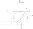
- Fig.4 and 5 the two extreme positions are shown in which the cover 36 is installed at an angle of +/- 50 degrees to the middle position. Accordingly, the head rail 12 can then be installed at an angle of up to 50 degrees in one direction or the other, whereby the slot-shaped outlet then assumes a horizontal orientation again. It has been shown that the cord lock 10 can be safely switched back and forth between the clamping and release positions with this additional horizontal guide through the slot-shaped outlet 38.
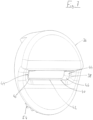
- Fig.6 shows the cord lock 10 with the cover 36 removed, so that the view through the opening 18 falls on the guide element 20 with its guide channel 30.
- the position shown corresponds to the clamping position.
- an internal toothing 48 is visible, which enables the cover 36 to be fixed in different angular positions, and second locking means 50, which in cooperation with first locking means 52 (see Fig.8 ) on the back of the cover 36 allow the cover 36 to snap into place in the opening 18 of the housing 14.
- the internal toothing 48 interacts with a toothed circle segment 54, which is also formed on the back of the cover 36 (see also Fig.8 ).
- the edge areas of the slot-shaped outlet can also be designed to be low-wear by making the entire cover out of a low-wear material.
Landscapes
- Engineering & Computer Science (AREA)
- Structural Engineering (AREA)
- Architecture (AREA)
- Civil Engineering (AREA)
- Curtains And Furnishings For Windows Or Doors (AREA)
Description
- Die Erfindung betrifft gemäß dem Oberbegriff von Anspruch 1 ein Schnurschloss zum Verklemmen einer oder mehrerer Betätigungsschnüre zum Verstellen der Ausfahrlänge eines Sonnenschutzbehangs, wobei das Schnurschloss ein bewegliches Führungselement mit einer Führungsbahn zum Führen der wenigstens einen Betätigungsschnur aufweist, das Druckflächen, mittels derer es durch die wenigstens eine Betätigungsschnur zwischen einer Klemmstellung und einer Freigabestellung bewegbar ist, und Klemmmittel aufweist, die in der Klemmstellung in einem die Führungsbahn verengenden, geringen Abstand zu einer ortsfesten Klemmfläche und in der Freigabestellung in einem die Führungsbahn freigebenden, größeren Abstand zu der Klemmfläche liegen.
- Ein solches Schnurschloss ist aus der
EP 690 199 B1 - Es hat sich aber gezeigt, dass bei einem Einbau einer solchen Sonnenschutzanlage, die häufig als Faltjalousie mit einem Plisseebehang ausgebildet sind, mit geneigter Kopfschiene der Umschaltvorgang mittels der Betätigungsschnur nur noch erschwert oder gar nicht mehr durchführen lässt, weil eine seitliche Verlagerung der Betätigungsschnur nur schwer möglich ist und ggf. durch eine angrenzende Wand oder dergleichen sogar völlig unmöglich wird.
- Aus der
EP 2 573 312 B1 ist zur Lösung dieses Problems eine Lösung bekannt, bei welcher das gesamte Schnurschloss relativ zur Kopfschiene der Anlage um eine senkrecht zur Verschattungsebene liegende Drehachse verschwenkbar ist. Das Umschalten zwischen einer Klemmstellung und einer Freigabestellung erfolgt durch Veränderung des Winkels eines Klemmhebels relativ zur Verschattungsfläche um eine Schwenkachse parallel zur Verschattungsebene. - Diese Lösung ist relativ aufwändig und es ist ein Gewöhnungsprozess der Nutzer an die neue Bedienungsart erforderlich.
- Die
JP S61 43399 U - Die Aufgabe der Erfindung besteht darin, ein Schnurschloss zu schaffen, dass an eine geneigte Einbaulage anpassbar ist.
- Hauptmerkmale der Erfindung sind im kennzeichnenden Teil von Anspruch 1 angegeben. Ausgestaltungen sind Gegenstand der Ansprüche 2 bis 14.
- Das Schnurschloss sieht erfindungsgemäß vor, dass ein schlitzförmiger Austritt für die wenigstens eine Betätigungsschnur in einem Deckel angeordnet ist, der in unterschiedlichen Winkellagen um eine Drehachse parallel zu einer Bewegungsebene des Führungselements relativ zu dem Schnurschloss derart festlegbar ist, dass nach einer Lagekorrektur auch bei geneigter Anlage der der schlitzförmige Austritt horizontal liegt und die Betätigungsschnur in geeigneter Weise in Richtung des Führungselements umlenkt..
- Es hat sich gezeigt, dass durch den als zusätzliche Führung für die wenigstens eine Bedienschnur dienenden schlitzförmigen Austritt in dem in seiner Winkellage relativ zum Führungselement des Schnurschlosses eine Anpassung an alle in der Praxis vorkommenden Neigungswinkel erreichen lässt, wobei das übliche Schnurschloss beibehalten werden kann und der Nutzer so auch intuitiv die Betätigungsschnur bedienen kann. Der nach der Lagekorrektur auch bei geneigter Anlage horizontal liegende Schlitz lenkt die Betätigungsschnur dann in geeigneter Weise in Richtung des Führungselements um. Der konstruktive Aufwand bleibt dabei sehr gering und es ist lediglich der sehr einfache Deckel als zusätzliches Bauteil erforderlich.
- Der Benutzer kann den Umschaltvorgang somit auslösen, ohne dass er die Betätigungsschnur in einen möglicherweise durch eine Wand versperrten oder für ihn nur mühsam zu erreichende Bereiche auslenken müsste.
- Sofern das Schnurschloss als Einheit z.B. an einem Stirnende einer Kopfschiene einer Sonnenschutzanlage angeordnet werden soll, ist es bevorzugt, dass das Führungselement und der Deckel an einem Gehäuse des Schnurschlosses angeordnet sind. Damit kann das komplette Schnurschloss einschließlich des Deckels an der Kopfschiene montiert werden. Grundsätzlich ist es aber auch möglich, den Deckel an der Kopfschiene der Sonnenschutzanlage in dem benötigten Winkel festzulegen, wozu dann eine geeignete Öffnung in der Kopfschiene vorgesehen ist.
- In an sich bekannter Weise sieht eine bevorzugte Ausführungsform der Erfindung vor, dass die Klemmmittel durch ein Zahnrad gebildet sind, das drehbar an dem Führungselement gelagert ist und mit einer ortsfesten Zahnstange zusammenwirkt. Diese aus der oben genannten
EP 0 690 199 B1 bekannte Lösung lässt sich gut mit der erfindungsgemäßen Lösung nach Anspruch 1 kombinieren. - In einer weiteren bevorzugten Ausführungsform der Erfindung ist vorgesehen, dass der Deckel eine kreis- oder teilkreisförmige Verzahnung aufweist, die in unterschiedlichen Drehwinkelstellungen in einer korrespondierenden Innenverzahnung des Schnurschlosses einsetzbar ist. Mittels korrespondierender Verzahnungen lässt sich einerseits die Winkeleinstellung besonders einfach vornehmen und andererseits bietet die Verzahnung auch bereits eine Verdrehsicherung, so dass sich die Winkellage unter den Bedienkräften auch ohne weitere Maßnahmen nach dem Einstellen nicht mehr verändern kann.
- In der Praxis ist es für die meisten Anwendungsfälle von Sonnenschutzanlagen der hier betroffenen Art ausreichend, dass die Winkellage des Deckels in Bezug auf eine Nulllage, in welcher der Öffnungsschlitz des Deckels parallel zur Bewegungsebene des Führungselements liegt, um bis zu +/- 60 Grad verstellbar ist, in aller Regel genügt es aber bereits, wenn die Winkellage um bis zu +/- 50 Grad in Bezug auf die Nulllage verstellbar ist.
- Eine besonders zweckmäßige und einfach zu montierende Ausführungsform der Erfindung sieht vor, dass der Deckel in der gewünschten Winkelstellung eingerastet ist, wobei vorzugsweise der Deckel erste Rastmittel aufweist, die mit zweiten, ortsfest zu der Klemmfläche angeordneten zweiten Rastmitteln zusammenwirken. Derartige Rastmittel lassen sich z.B. bei Kunststoffteilen sehr einfach umsetzen, ohne die Herstellungskosten wesentlich zu erhöhen.
- Eine konstruktiv besonders zweckmäßige Weiterbildung der Erfindung sieht vor, dass die Rastmittel und die Verzahnung des Deckels jeweils über einen Teilbereich eines Umfanges angeordnet sind.
- Bei einer Montage des Deckels an dem Gehäuse ist es zweckmäßig, dass auch die zweiten Rastmittel an dem Gehäuse angeordnet sind.
- Um unter großen Neigungswinkeln zu vermeiden, dass die Betätigungsschnur sich verklemmen kann oder die Funktion durch Reibungsverluste eingeschränkt wird, ist es von besonderem Vorteil, dass bei einer noch weiteren Ausführungsform der Schlitz zwischen seinen Seitenflanken und der unteren Wandung und/oder an den Außenkanten mit Übergangsradien ausgebildet ist.
- Vorzugsweise ist weiterhin vorgesehen, dass der schlitzförmige Austritt seitlich und bodenseitig durch eine Metalleinlage ausgebildet ist. Diese z.B. durch einen in eine Kunststoffform vor dem Spritzgießen eingelegten Drahtbügel gebildete Metalleinlage verhindert einen vorzeitigen Verschleiß an den durch die Bedienkräfte hoch belasteten Stellen. Es ist aber auch der Einsatz hochfester Kunststoffe als Material für den Deckel möglich. Der Einsatz eines Runddrahtes als Metalleinlage hat den Vorteil, dass auch die zuvor erwähnten Radien ausgebildet werden können.
- Gegenstand der Erfindung ist auch eine Sonnenschutzanlage mit einem mittels wenigstens einer Betätigungsschnur verstellbaren Behang und einem Schnurschloss, das an einer Kopfschiene der Sonnenschutzanlage festgelegt ist und nach einem der vorgehenden Ansprüche ausgebildet ist. Der Vorteil einer solchen Anlage ist ihre universelle Anpassbarkeit an unterschiedliche Neigungswinkel.
- Wie bereits erwähnt, kann bei einer solchen Anlage vorgesehen werden, dass der Deckel des Schnurschlosses an der Kopfschiene mit variabler Winkellage festgelegt ist, wenn aus konstruktiven oder optischen Gründen eine Festlegung des Deckels an dem Gehäuse des Schnurschlosses nicht erwünscht ist.
- Bei einem weit verbreiteten Einsatzgebiet der Schnurbetätigung ist vorgesehen, dass die Sonnenschutzanlage als Faltjalousie mit einem Plisseebehang ausgebildet ist.
- Weitere Merkmale, Einzelheiten und Vorteile der Erfindung ergeben sich aus dem Wortlaut der Ansprüche sowie aus der folgenden Beschreibung von Ausführungsbeispielen anhand der Zeichnungen. Es zeigen:
-
Fig. 1 einen Längsschnitt durch ein Schnurschloss in der Klemmstellung; -
Fig. 2 einen Längsschnitt durch das Schnurschloss in der Freigabestellung; -
Fig. 3 eine Frontansicht des Schnurschlosses mit einem Deckel in der Neutralstellung; -
Fig. 4 eine Frontansicht des Deckels in einer ersten maximalen Winkelstellung; -
Fig. 5 eine Frontansicht des Deckels in der zweiten maximalen Winkelstellung; -
Fig. 6 eine Frontansicht des Schnurschlosses mit abgenommenem Deckel; -
Fig. 7 eine perspektivische Frontansicht des Deckels; -
Fig. 8 eine perspektivische Rückansicht des Deckels. - In
Fig. 1 ist im Schnitt ein Schnurschloss 10 gezeigt, dass in das Stirnende einer Kopfschiene 12 einer als Faltjalousie ausgebildeten Sonnenschutzanlage (nicht näher gezeigt) eingesetzt ist. Das Schnurschloss 10 besitzt ein bevorzugt aus Kunststoff hergestelltes Gehäuse 14 mit einer ersten Öffnung 16 zur Kopfschiene 12 und einer zweiten Öffnung 18 zur Vorderseite der Anlage. Wenigstens eine Betätigungsschnur (nicht gezeigt) läuft durch das Schnurschloss und tritt durch die Öffnung an der Vorderseite für den Nutzer zugänglich aus. In der Regel sind dabei mehrere Bedienschnüre vorhanden, deren Zahl hängt von dem Behangkonzept ab. Mittels der Bedienschnüre lässt sich die Ausfahrlänge des Behanges variieren, so lange das Schnurschloss die Bedienschnüre freigibt. Um eine gewünschte Einstellung beizubehalten, kann das Schnurrschloss 10 in eine die Bedienschnüre blockierende Stellung geschaltet werden. - Zum Arretieren der Bedienschnüre verfügt das Schnurschloss 10 über ein schwimmend in einer Bewegungsebene parallel zur Kopfschiene beweglich gelagertes Führungselement 20, das zwischen einer Klemmstellung (siehe
Fig. 1 ), in welcher die Betätigungsschnüre verklemmt sind, und einer Freigabestellung (sieheFig. 2 ), in welcher die Betätigungsschnüre verstellt werden können, umschaltbar ist. - Das Führungselement 20 besitzt ein als Klemmmittel wirkendes Zahnrad 22, das drehbar an dem Führungselement 20 gelagert ist. Das Zahnrad 22 wirkt unter Zwischenlage der dort geführten Betätigungsschnüre mit einer runden Klemmfläche 24 zusammen, die ortsfest bezüglich des Gehäuses 14 ausgebildet ist. Die Betätigungsschnüre sind in der Klemmstellung in einem Spalt 26 zwischen der Klemmfläche 24 und der Verzahnung des Zahnrades 22 verklemmt und halten das Gewicht des an Ihnen aufgehängten Plisseebehanges. Wie aus
Fig. 1 gut zu erkennen ist, greift das Zahnrad 22 außerdem in eine gehäuseseitig vorgesehene Zahnstange 28 ein. Unter der über die Betätigungsschnüre auf die Verzahnung wirkende Gewichtskraft des Behanges ist das Zahnrad folglich bestrebt, sich im Uhrzeigersinn auf der Zahnstange 28 abzurollen, so dass die Klemmkraft verstärkt wird. - Wie aus
Fig. 1 weiterhin gut zu erkennen ist, verfügt das Führungselement 20 über einen Führungskanal 30 zwischen einer ersten Druckfläche 32 und einer zweiten Druckfläche 34. Um das die Arretierstellung aufzuheben und den Behang über die Betätigungsschnur verstellen zu können, kann diese durch den Benutzer im Sinne der Darstellung inFig. 1 nach links gegen die erste Druckfläche 32 gezogen werden. Hierdurch wird bei gleichzeitigem Kompensieren der über die Betätigungsschnüre auf die Klemmstelle wirkenden Behangkräfte auf das Führungselement 20 eine Lösekraft ausgeübt, so dass das Zahnrad 22 aus der Zahnstange 28 ausgerückt werden kann und sich das Führungselement 20 in die inFig. 2 gezeigte Freigabestellung bewegt. In dieser Position bestehen in der Führungsbahn der Betätigungsschnüre keine verengten Abschnitte mehr, die den Lauf der Bedienschüre behindern könnten. - Um das Schnurschloss 10 wieder zu verriegeln, werden die Bedienschnüre in die entgegengesetzte Richtung (nach rechts im Sinne der Darstellung in
Fig. 2 ) ausgelenkt, so dass die Bedienschnüre eine Kraft auf die zweite Druckfläche 34 ausüben. Diese bewegt das Führungselement derart in Richtung der Zahnstange 28, dass das Zahnrad 22 mit dieser in Eingriff gelangt. Da in dieser Position die Bedienschnüre bereits über das Zahnrad 22 laufen, führt ein leichtes Nachlassen an den Bedienschnüren dazu, dass sich das Zahnrad 22 wiederum unter der Gewichtskraft des Behanges auf der Zahnstange 28 abrollt, bis es wiederum in die inFig. 1 gezeigte Klemmstellung gelangt. - In
Fig. 1 und2 ist auch ein Deckel 36 gezeigt, der in die zweite Öffnung 18 in dem Gehäuse 14 eingesetzt und mit einem schlitzförmigen Austritt 38 für die Betätigungsschnüre versehen ist. Der Austritt ermöglicht es mit seiner schlitzförmigen Ausbildung, die Bedienschnüre für die Umschaltvorgänge an die Druckflächen 23, 34 zu ziehen. - In
Fig. 1 und2 ist auch ein Drahtbügel 40 erkennbar, der in den Deckel 36 eingearbeitet ist und eine verschleißarme Gleitfläche für die Bedienschnüre im hochbelasteten unteren Rand 42 und insbesondere den seitlichen Rändern 44 und den dazwischenliegenden Übergangsbereichen 46 bildet. Der Radius des Drahtbügels 40 mindert auch die Reibungsverluste bei der Bedienung der Betätigungsschnüre. Falls gewünscht lassen sich die Radien auch im Material des Deckels ohne Drahtbügel 40 ausbilden. Zur Minderung des Verschleißes ist für den Deckel der Einsatz eines hochfesten Kunststoffes empfehlenswert. - Bei einem unveränderlich zu der Kopfschiene 12 der Sonnenschutzanlage angeordneten Austritt ergeben sich Probleme bei einem geneigten Einbau der Kopfschiene, da dann die Bedienschnüre insbesondere dann nicht mehr einfach gegen die Druckflächen verschwenkt werden können, wenn neben der Sonnenschutzanlage eine Wand liegt.
- Das Schnurschloss 10 bietet daher die Möglichkeit, den Deckel 36 in verschiedenen Winkellagen an dem Gehäuse 14 des Schnurschlosses 10 festlegen zu können, so dass auch bei einer geneigt angeordneten Kopfschiene 12 eine horizontale Ausrichtung des schlitzförmigen Austrittes 38 ermöglicht wird, in dem der Deckel 36 entsprechend verdreht in das Gehäuse 14 eingesetzt wird. Eine streng horizontale Ausrichtung ist im Übrigen nicht erforderlich.
-
Fig. 3 zeigt die Anordnung des Deckels in der Mittellage, die sich für horizontal einzubauende Kopfschienen eignet und den Standardfall darstellt. - In
Fig. 4 und5 sind die beiden Extremlagen gezeigt, in denen der Deckel 36 mit einem Winkel von +/- 50 Grad zu Mittellage eingebaut ist. Entsprechend kann die Kopfschiene 12 dann in einem Winkel um bis zu 50 Grad in der einen oder anderen Richtung geneigt eingebaut werden, wobei dann der schlitzförmige Austritt wieder eine horizontale Ausrichtung annimmt. Es hat sich gezeigt, dass sich das Schnurschloss 10 mit dieser zusätzlichen horizontalen Führung durch den schlitzförmigen Austritt 38 sicher zwischen der Klemm- und Freigabestellung hin und her umschalten lässt. -
Fig. 6 zeigt das Schnurschloss 10 mit abgenommenem Deckel 36, so dass der Blick durch die Öffnung 18 auf das Führungselement 20 mit seinem Führungskanal 30 fällt. Die gezeigte Stellung entspricht hierbei der Klemmstellung. Am Rand der Öffnung 18 sind einerseits eine Innenverzahnung 48, die die Festlegung des Deckels 36 in verschiedenen Winkelstellungen ermöglicht, und zweite Rastmittel 50 sichtbar, die im Zusammenwirken mit ersten Rastmitteln 52 (sieheFig. 8 ) an der Rückseite des Deckels 36 ein Einrasten des Deckels 36 in der Öffnung 18 des Gehäuses 14 ermöglichen. Die Innenverzahnung 48 wirkt mit einem Zahnkreissegment 54 zusammen, das ebenfalls an der Rückseite des Deckels 36 ausgebildet ist (siehe ebenfallsFig. 8 ). - Der Aufbau des Deckels 36 des gezeigten Ausführungsbeispiels wird durch die bereits in Bezug genommene
Fig. 7 undFig. 8 deutlich. Neben den bereits erörterten ersten Rastmitteln 52 und dem Zahnkreissegment 54 ist ausFig. 8 auch noch die Ausbildung des schlitzförmigen Austrittes 38 gut erkennbar. - Für die Führung der Betätigungsschnüre dienen praktisch ausschließlich der untere Rand 42, die beiden seitlichen Ränder 42 und die Übergangsbereiche 46, die alle durch einen in den Deckel 36 eingearbeiteten Drahtbügel 40 ausgebildet sind.
- Die Erfindung ist nicht auf eine der vorbeschriebenen Ausführungsformen beschränkt, sondern in vielfältiger Weise abwandelbar.
- Alternativ zu einer Metalleinlage können die Randbereiche des schlitzförmigen Austrittes auch dadurch verschleißarm ausgebildet werden, dass der gesamte Deckel aus einem verschleißarmen Material besteht.
- Anstelle eines mit dem Gehäuse verrasteten Deckels 36 ist es auch möglich, das Schnurschloss in einer Kopfschiene mit einem Durchtritt in einer Seitenwandung anzuordnen, in welcher dann der Deckel unmittelbar in der gewünschten Winkellage angeordnet wird. Dies bedeutet, dass die bei dem zuvor dem Gehäuse zugeordneten zweiten Rastelemente und der Innenverzahnung oder auch gleichwirkende Befestigungselemente an der Kopfschiene angeordnet werden.
- Sämtliche aus den Ansprüchen, der Beschreibung und der Zeichnung hervorgehenden Merkmale und Vorteile, einschließlich konstruktiver Einzelheiten, räumlicher Anordnungen und Verfahrensschritten, können sowohl für sich als auch in den verschiedensten Kombinationen erfindungswesentlich sein, solange sie in den Anwendungsbereich der anhängenden Ansprüche fallen.
-
- 10
- Schnurschloss
- 12
- Kopfschiene
- 14
- Gehäuse
- 16
- erste, schienenseitige Öffnung
- 18
- zweite, vorderseitige Öffnung
- 20
- Führungselement
- 22
- Zahnrad als Klemmmittel
- 24
- Klemmfläche
- 26
- Klemmspalt
- 28
- Zahnstange
- 30
- Führungskanal
- 32
- erste Druckfläche
- 34
- zweite Druckfläche
- 36
- Deckel
- 38
- schlitzförmiger Austritt
- 40
- Drahtbügel
- 42
- unterer Rand des Austrittes
- 44
- seitliche Ränder des Austrittes
- 46
- Übergangsbereiche
- 48
- Innenverzahnung
- 50
- zweite Rastmittel
- 52
- erste Rastmittel
- 54
- Zahnkreissegment
Claims (14)
- Schnurschloss (10) zum Verklemmen einer oder mehrerer Betätigungsschnüre zum Verstellen der Ausfahrlänge eines Sonnenschutzbehangs, wobei das Schnurschloss (10) ein bewegliches Führungselement (20) mit einer Führungsbahn (30) zum Führen der wenigstens einen Betätigungsschnur aufweist, das Druckflächen (32, 34), mittels derer das Führungselement (20) durch die wenigstens eine Betätigungsschnur zwischen einer Klemmstellung und einer Freigabestellung bewegbar ist, und Klemmmittel (22) aufweist, die in der Klemmstellung in einem die Führungsbahn (30) verengenden, geringen Abstand zu einer ortsfesten Klemmfläche (24) und in der Freigabestellung in einem die Führungsbahn freigebenden, größeren Abstand zu der Klemmfläche (24) liegen, dadurch gekennzeichnet, dass ein schlitzförmiger Austritt (38) für die wenigstens eine Betätigungsschnur in einem Deckel (36) angeordnet ist, der in unterschiedlichen Winkellagen um eine Drehachse parallel zu einer Bewegungsebene des Führungselements (20) relativ zu dem Schnurschloss (10) derart festlegbar ist, dass nach einer Lagekorrektur auch bei geneigter Anlage der schlitzförmige Austritt (38) horizontal liegt und die Betätigungsschnur in geeigneter Weise in Richtung des Führungselements (20) umlenkt.
- Schnurschloss nach Anspruch 1, dadurch gekennzeichnet, dass das Führungselement (20) und der Deckel (36) an einem Gehäuse (14) des Schnurschlosses (10) angeordnet sind.
- Schnurschloss nach Anspruch 1 oder 2, dadurch gekennzeichnet, dass die Klemmmittel durch ein Zahnrad (22) gebildet sind, das drehbar an dem Führungselement (20) gelagert ist und mit einer ortsfesten Zahnstange (28) zusammenwirkt.
- Schnurschloss nach einem der Ansprüche 1 bis 3, dadurch gekennzeichnet, dass der Deckel (36) eine kreis- oder teilkreisförmige Verzahnung (54) aufweist, die in unterschiedlichen Drehwinkelstellungen in einer korrespondierenden Innenverzahnung (48) des Schnurschlosses (10) einsetzbar ist.
- Schnurschloss nach einem der vorhergehenden Ansprüche, dadurch gekennzeichnet, dass die Winkellage des Deckels (36) in Bezug auf eine Nulllage, in welcher der schlitzförmige Austritt (38) des Deckels (16) parallel zur Bewegungsebene des Führungselements liegt, um bis zu +/- 60 Grad verstellbar ist.
- Schnurschloss nach Anspruch 5, dadurch gekennzeichnet, dass die Winkellage um bis zu +/- 50 Grad in Bezug auf die Nulllage verstellbar ist.
- Schnurschloss nach einem der vorgehenden Ansprüche, dadurch gekennzeichnet, dass der Deckel (36) in der gewünschten Winkelstellung eingerastet ist.
- Schnurschloss nach Anspruch 7, dadurch gekennzeichnet, dass der Deckel (36) erste Rastmittel (52) aufweist, die mit zweiten, ortsfest zu der Klemmfläche (24) angeordneten zweiten Rastmitteln (50) zusammenwirken
- Schnurschloss nach Anspruch 8, dadurch gekennzeichnet, dass die zweiten Rastmittel (50) an dem Gehäuse (14) angeordnet sind.
- Schnurschloss nach einem der vorhergehenden Ansprüche, dadurch gekennzeichnet, dass der schlitzförmige Austritt (38) zwischen seinen Seitenflanken (44) und der unteren Wandung (42) und/oder an den Außenkanten mit Übergangsradien ausgebildet ist.
- Schnurschloss nach einem der vorhergehenden Ansprüche, dadurch gekennzeichnet, dass der schlitzförmige Austritt (38) seitlich und bodenseitig durch eine Metalleinlage ausgebildet ist.
- Sonnenschutzanlage mit einem mittels wenigstens einer Betätigungsschnur verstellbaren Behang und einem Schnurschloss (10), das an einer Kopfschiene (12) der Sonnenschutzanlage festgelegt ist und nach einem der vorgehenden Ansprüche ausgebildet ist.
- Sonnenschutzanlage nach Anspruch 12, dadurch gekennzeichnet, dass der Deckel (36) des Schnurschlosses (10) an der Kopfschiene (12) mit variabler Winkellage festgelegt ist.
- Sonnenschutzanlage nach Anspruch 12 oder 13, dadurch gekennzeichnet, dass diese als Faltjalousie mit einem Plisseebehang ausgebildet ist.
Applications Claiming Priority (1)
| Application Number | Priority Date | Filing Date | Title |
|---|---|---|---|
| DE102019127636.5A DE102019127636B3 (de) | 2019-10-14 | 2019-10-14 | Schnurschloss für Sonnenschutzanlagen |
Publications (2)
| Publication Number | Publication Date |
|---|---|
| EP3808229A1 EP3808229A1 (de) | 2021-04-21 |
| EP3808229B1 true EP3808229B1 (de) | 2024-04-17 |
Family
ID=72826802
Family Applications (1)
| Application Number | Title | Priority Date | Filing Date |
|---|---|---|---|
| EP20201151.6A Active EP3808229B1 (de) | 2019-10-14 | 2020-10-09 | Schnurschloss für sonnenschutzanlagen |
Country Status (2)
| Country | Link |
|---|---|
| EP (1) | EP3808229B1 (de) |
| DE (1) | DE102019127636B3 (de) |
Family Cites Families (5)
| Publication number | Priority date | Publication date | Assignee | Title |
|---|---|---|---|---|
| JPS6143399U (ja) * | 1984-08-24 | 1986-03-20 | 株式会社 ニチベイ | ブラインド用コ−ドストツパ装置 |
| NL9401081A (nl) * | 1994-06-28 | 1996-02-01 | Verosol Nederland Bv | Koordrem. |
| DE29816846U1 (de) * | 1998-09-19 | 1999-01-28 | Reko Kunststofftechnik und Maschinenbau GmbH, 97828 Marktheidenfeld | Positionierbare Schnurbremse |
| TWM253300U (en) * | 2004-04-12 | 2004-12-21 | Ching Feng Home Fashions Co | Pull cord control device for venetian blind |
| DE102011110833A1 (de) * | 2011-08-23 | 2013-02-28 | Hunter Douglas Industries Switzerland Gmbh | Schnurschloss |
-
2019
- 2019-10-14 DE DE102019127636.5A patent/DE102019127636B3/de active Active
-
2020
- 2020-10-09 EP EP20201151.6A patent/EP3808229B1/de active Active
Also Published As
| Publication number | Publication date |
|---|---|
| EP3808229A1 (de) | 2021-04-21 |
| DE102019127636B3 (de) | 2021-01-21 |
Similar Documents
| Publication | Publication Date | Title |
|---|---|---|
| DE9420359U1 (de) | Auszugssperre für übereinander angeordnete Schubladen | |
| EP2188148A2 (de) | Verstelleinrichtung zur längsverstellung einer kraftfahrzeugkomponente | |
| EP3835526A1 (de) | Schiebe- und drehflügelsystem | |
| EP4162133A1 (de) | Führungssystem | |
| EP3631131B1 (de) | Band zur um eine scharnierachse scharniergelenkigen befestigung eines flügels an einem rahmen | |
| DE10150709A1 (de) | Markise | |
| AT524607B1 (de) | Anordnung zur Führung eines bewegbaren Möbelteils | |
| EP1783318B1 (de) | Schnurspanner zum Spannen von Schnüren an Verschattungsanlagen sowie Verschattungsanlage | |
| EP4382720B1 (de) | Schienenvorrichtung zum lagern einer elementschiene, die zum seitlichen führen eines sonnenschutzelements zum verhindern des eintretens von sonnenlicht in ein gebäude ausgelegt ist | |
| DE102019127636B3 (de) | Schnurschloss für Sonnenschutzanlagen | |
| DE19930785B4 (de) | Rolladen, insbesondere Trapezrolladen | |
| DE20017852U1 (de) | Luft-Ausströmer, insbesondere zur Fahrzeugklimatisierung | |
| EP2192075B1 (de) | Seilflasche | |
| AT393869B (de) | Rolladen | |
| EP3817627B1 (de) | Stuhl | |
| AT502965B1 (de) | Vorrichtung zur regelung der öffnungsfolge von zweiflügeligen schwenktüren | |
| EP4336007B1 (de) | Beschlag für eine schiebetür sowie schiebetür | |
| DE202007000136U1 (de) | Jalousie | |
| DE10050176B4 (de) | Einrastbare Führungsschiene | |
| DE202005009745U1 (de) | Beschlaganordnung | |
| DE19637453C2 (de) | Torblattverriegelung | |
| EP4245932A1 (de) | Sanitäre wandhalterungsvorrichtung | |
| DE29520732U1 (de) | Auszugsperre für übereinander angeordnete Schubladen | |
| EP1696099A1 (de) | Jalousie | |
| EP0617191A1 (de) | Führungsschienenanordnung für eine Wintergartenmarkise o. dgl. |
Legal Events
| Date | Code | Title | Description |
|---|---|---|---|
| PUAI | Public reference made under article 153(3) epc to a published international application that has entered the european phase |
Free format text: ORIGINAL CODE: 0009012 |
|
| STAA | Information on the status of an ep patent application or granted ep patent |
Free format text: STATUS: THE APPLICATION HAS BEEN PUBLISHED |
|
| AK | Designated contracting states |
Kind code of ref document: A1 Designated state(s): AL AT BE BG CH CY CZ DE DK EE ES FI FR GB GR HR HU IE IS IT LI LT LU LV MC MK MT NL NO PL PT RO RS SE SI SK SM TR |
|
| AX | Request for extension of the european patent |
Extension state: BA ME |
|
| STAA | Information on the status of an ep patent application or granted ep patent |
Free format text: STATUS: REQUEST FOR EXAMINATION WAS MADE |
|
| 17P | Request for examination filed |
Effective date: 20211021 |
|
| RBV | Designated contracting states (corrected) |
Designated state(s): AL AT BE BG CH CY CZ DE DK EE ES FI FR GB GR HR HU IE IS IT LI LT LU LV MC MK MT NL NO PL PT RO RS SE SI SK SM TR |
|
| GRAP | Despatch of communication of intention to grant a patent |
Free format text: ORIGINAL CODE: EPIDOSNIGR1 |
|
| STAA | Information on the status of an ep patent application or granted ep patent |
Free format text: STATUS: GRANT OF PATENT IS INTENDED |
|
| INTG | Intention to grant announced |
Effective date: 20230306 |
|
| GRAJ | Information related to disapproval of communication of intention to grant by the applicant or resumption of examination proceedings by the epo deleted |
Free format text: ORIGINAL CODE: EPIDOSDIGR1 |
|
| STAA | Information on the status of an ep patent application or granted ep patent |
Free format text: STATUS: REQUEST FOR EXAMINATION WAS MADE |
|
| INTC | Intention to grant announced (deleted) | ||
| GRAP | Despatch of communication of intention to grant a patent |
Free format text: ORIGINAL CODE: EPIDOSNIGR1 |
|
| STAA | Information on the status of an ep patent application or granted ep patent |
Free format text: STATUS: GRANT OF PATENT IS INTENDED |
|
| INTG | Intention to grant announced |
Effective date: 20231109 |
|
| GRAS | Grant fee paid |
Free format text: ORIGINAL CODE: EPIDOSNIGR3 |
|
| GRAA | (expected) grant |
Free format text: ORIGINAL CODE: 0009210 |
|
| STAA | Information on the status of an ep patent application or granted ep patent |
Free format text: STATUS: THE PATENT HAS BEEN GRANTED |
|
| AK | Designated contracting states |
Kind code of ref document: B1 Designated state(s): AL AT BE BG CH CY CZ DE DK EE ES FI FR GB GR HR HU IE IS IT LI LT LU LV MC MK MT NL NO PL PT RO RS SE SI SK SM TR |
|
| REG | Reference to a national code |
Ref country code: GB Ref legal event code: FG4D Free format text: NOT ENGLISH |
|
| REG | Reference to a national code |
Ref country code: CH Ref legal event code: EP |
|
| REG | Reference to a national code |
Ref country code: IE Ref legal event code: FG4D Free format text: LANGUAGE OF EP DOCUMENT: GERMAN Ref country code: DE Ref legal event code: R096 Ref document number: 502020007684 Country of ref document: DE |
|
| REG | Reference to a national code |
Ref country code: LT Ref legal event code: MG9D |
|
| REG | Reference to a national code |
Ref country code: NL Ref legal event code: MP Effective date: 20240417 |
|
| PG25 | Lapsed in a contracting state [announced via postgrant information from national office to epo] |
Ref country code: NL Free format text: LAPSE BECAUSE OF FAILURE TO SUBMIT A TRANSLATION OF THE DESCRIPTION OR TO PAY THE FEE WITHIN THE PRESCRIBED TIME-LIMIT Effective date: 20240417 |
|
| PG25 | Lapsed in a contracting state [announced via postgrant information from national office to epo] |
Ref country code: NL Free format text: LAPSE BECAUSE OF FAILURE TO SUBMIT A TRANSLATION OF THE DESCRIPTION OR TO PAY THE FEE WITHIN THE PRESCRIBED TIME-LIMIT Effective date: 20240417 |
|
| PG25 | Lapsed in a contracting state [announced via postgrant information from national office to epo] |
Ref country code: IS Free format text: LAPSE BECAUSE OF FAILURE TO SUBMIT A TRANSLATION OF THE DESCRIPTION OR TO PAY THE FEE WITHIN THE PRESCRIBED TIME-LIMIT Effective date: 20240817 |
|
| PG25 | Lapsed in a contracting state [announced via postgrant information from national office to epo] |
Ref country code: BG Free format text: LAPSE BECAUSE OF FAILURE TO SUBMIT A TRANSLATION OF THE DESCRIPTION OR TO PAY THE FEE WITHIN THE PRESCRIBED TIME-LIMIT Effective date: 20240417 |
|
| PG25 | Lapsed in a contracting state [announced via postgrant information from national office to epo] |
Ref country code: FI Free format text: LAPSE BECAUSE OF FAILURE TO SUBMIT A TRANSLATION OF THE DESCRIPTION OR TO PAY THE FEE WITHIN THE PRESCRIBED TIME-LIMIT Effective date: 20240417 Ref country code: HR Free format text: LAPSE BECAUSE OF FAILURE TO SUBMIT A TRANSLATION OF THE DESCRIPTION OR TO PAY THE FEE WITHIN THE PRESCRIBED TIME-LIMIT Effective date: 20240417 |
|
| PG25 | Lapsed in a contracting state [announced via postgrant information from national office to epo] |
Ref country code: GR Free format text: LAPSE BECAUSE OF FAILURE TO SUBMIT A TRANSLATION OF THE DESCRIPTION OR TO PAY THE FEE WITHIN THE PRESCRIBED TIME-LIMIT Effective date: 20240718 |
|
| PG25 | Lapsed in a contracting state [announced via postgrant information from national office to epo] |
Ref country code: PT Free format text: LAPSE BECAUSE OF FAILURE TO SUBMIT A TRANSLATION OF THE DESCRIPTION OR TO PAY THE FEE WITHIN THE PRESCRIBED TIME-LIMIT Effective date: 20240819 |
|
| PG25 | Lapsed in a contracting state [announced via postgrant information from national office to epo] |
Ref country code: ES Free format text: LAPSE BECAUSE OF FAILURE TO SUBMIT A TRANSLATION OF THE DESCRIPTION OR TO PAY THE FEE WITHIN THE PRESCRIBED TIME-LIMIT Effective date: 20240417 |
|
| PG25 | Lapsed in a contracting state [announced via postgrant information from national office to epo] |
Ref country code: PL Free format text: LAPSE BECAUSE OF FAILURE TO SUBMIT A TRANSLATION OF THE DESCRIPTION OR TO PAY THE FEE WITHIN THE PRESCRIBED TIME-LIMIT Effective date: 20240417 |
|
| PG25 | Lapsed in a contracting state [announced via postgrant information from national office to epo] |
Ref country code: LV Free format text: LAPSE BECAUSE OF FAILURE TO SUBMIT A TRANSLATION OF THE DESCRIPTION OR TO PAY THE FEE WITHIN THE PRESCRIBED TIME-LIMIT Effective date: 20240417 |
|
| PG25 | Lapsed in a contracting state [announced via postgrant information from national office to epo] |
Ref country code: PT Free format text: LAPSE BECAUSE OF FAILURE TO SUBMIT A TRANSLATION OF THE DESCRIPTION OR TO PAY THE FEE WITHIN THE PRESCRIBED TIME-LIMIT Effective date: 20240819 Ref country code: PL Free format text: LAPSE BECAUSE OF FAILURE TO SUBMIT A TRANSLATION OF THE DESCRIPTION OR TO PAY THE FEE WITHIN THE PRESCRIBED TIME-LIMIT Effective date: 20240417 Ref country code: NO Free format text: LAPSE BECAUSE OF FAILURE TO SUBMIT A TRANSLATION OF THE DESCRIPTION OR TO PAY THE FEE WITHIN THE PRESCRIBED TIME-LIMIT Effective date: 20240717 Ref country code: LV Free format text: LAPSE BECAUSE OF FAILURE TO SUBMIT A TRANSLATION OF THE DESCRIPTION OR TO PAY THE FEE WITHIN THE PRESCRIBED TIME-LIMIT Effective date: 20240417 Ref country code: IS Free format text: LAPSE BECAUSE OF FAILURE TO SUBMIT A TRANSLATION OF THE DESCRIPTION OR TO PAY THE FEE WITHIN THE PRESCRIBED TIME-LIMIT Effective date: 20240817 Ref country code: HR Free format text: LAPSE BECAUSE OF FAILURE TO SUBMIT A TRANSLATION OF THE DESCRIPTION OR TO PAY THE FEE WITHIN THE PRESCRIBED TIME-LIMIT Effective date: 20240417 Ref country code: GR Free format text: LAPSE BECAUSE OF FAILURE TO SUBMIT A TRANSLATION OF THE DESCRIPTION OR TO PAY THE FEE WITHIN THE PRESCRIBED TIME-LIMIT Effective date: 20240718 Ref country code: FI Free format text: LAPSE BECAUSE OF FAILURE TO SUBMIT A TRANSLATION OF THE DESCRIPTION OR TO PAY THE FEE WITHIN THE PRESCRIBED TIME-LIMIT Effective date: 20240417 Ref country code: ES Free format text: LAPSE BECAUSE OF FAILURE TO SUBMIT A TRANSLATION OF THE DESCRIPTION OR TO PAY THE FEE WITHIN THE PRESCRIBED TIME-LIMIT Effective date: 20240417 Ref country code: BG Free format text: LAPSE BECAUSE OF FAILURE TO SUBMIT A TRANSLATION OF THE DESCRIPTION OR TO PAY THE FEE WITHIN THE PRESCRIBED TIME-LIMIT Effective date: 20240417 Ref country code: RS Free format text: LAPSE BECAUSE OF FAILURE TO SUBMIT A TRANSLATION OF THE DESCRIPTION OR TO PAY THE FEE WITHIN THE PRESCRIBED TIME-LIMIT Effective date: 20240717 |
|
| PG25 | Lapsed in a contracting state [announced via postgrant information from national office to epo] |
Ref country code: DK Free format text: LAPSE BECAUSE OF FAILURE TO SUBMIT A TRANSLATION OF THE DESCRIPTION OR TO PAY THE FEE WITHIN THE PRESCRIBED TIME-LIMIT Effective date: 20240417 |
|
| REG | Reference to a national code |
Ref country code: DE Ref legal event code: R097 Ref document number: 502020007684 Country of ref document: DE |
|
| PG25 | Lapsed in a contracting state [announced via postgrant information from national office to epo] |
Ref country code: EE Free format text: LAPSE BECAUSE OF FAILURE TO SUBMIT A TRANSLATION OF THE DESCRIPTION OR TO PAY THE FEE WITHIN THE PRESCRIBED TIME-LIMIT Effective date: 20240417 |
|
| PG25 | Lapsed in a contracting state [announced via postgrant information from national office to epo] |
Ref country code: CZ Free format text: LAPSE BECAUSE OF FAILURE TO SUBMIT A TRANSLATION OF THE DESCRIPTION OR TO PAY THE FEE WITHIN THE PRESCRIBED TIME-LIMIT Effective date: 20240417 |
|
| PG25 | Lapsed in a contracting state [announced via postgrant information from national office to epo] |
Ref country code: SK Free format text: LAPSE BECAUSE OF FAILURE TO SUBMIT A TRANSLATION OF THE DESCRIPTION OR TO PAY THE FEE WITHIN THE PRESCRIBED TIME-LIMIT Effective date: 20240417 Ref country code: RO Free format text: LAPSE BECAUSE OF FAILURE TO SUBMIT A TRANSLATION OF THE DESCRIPTION OR TO PAY THE FEE WITHIN THE PRESCRIBED TIME-LIMIT Effective date: 20240417 |
|
| PG25 | Lapsed in a contracting state [announced via postgrant information from national office to epo] |
Ref country code: SM Free format text: LAPSE BECAUSE OF FAILURE TO SUBMIT A TRANSLATION OF THE DESCRIPTION OR TO PAY THE FEE WITHIN THE PRESCRIBED TIME-LIMIT Effective date: 20240417 |
|
| PG25 | Lapsed in a contracting state [announced via postgrant information from national office to epo] |
Ref country code: SM Free format text: LAPSE BECAUSE OF FAILURE TO SUBMIT A TRANSLATION OF THE DESCRIPTION OR TO PAY THE FEE WITHIN THE PRESCRIBED TIME-LIMIT Effective date: 20240417 Ref country code: SK Free format text: LAPSE BECAUSE OF FAILURE TO SUBMIT A TRANSLATION OF THE DESCRIPTION OR TO PAY THE FEE WITHIN THE PRESCRIBED TIME-LIMIT Effective date: 20240417 Ref country code: RO Free format text: LAPSE BECAUSE OF FAILURE TO SUBMIT A TRANSLATION OF THE DESCRIPTION OR TO PAY THE FEE WITHIN THE PRESCRIBED TIME-LIMIT Effective date: 20240417 Ref country code: EE Free format text: LAPSE BECAUSE OF FAILURE TO SUBMIT A TRANSLATION OF THE DESCRIPTION OR TO PAY THE FEE WITHIN THE PRESCRIBED TIME-LIMIT Effective date: 20240417 Ref country code: DK Free format text: LAPSE BECAUSE OF FAILURE TO SUBMIT A TRANSLATION OF THE DESCRIPTION OR TO PAY THE FEE WITHIN THE PRESCRIBED TIME-LIMIT Effective date: 20240417 Ref country code: CZ Free format text: LAPSE BECAUSE OF FAILURE TO SUBMIT A TRANSLATION OF THE DESCRIPTION OR TO PAY THE FEE WITHIN THE PRESCRIBED TIME-LIMIT Effective date: 20240417 |
|
| PG25 | Lapsed in a contracting state [announced via postgrant information from national office to epo] |
Ref country code: IT Free format text: LAPSE BECAUSE OF FAILURE TO SUBMIT A TRANSLATION OF THE DESCRIPTION OR TO PAY THE FEE WITHIN THE PRESCRIBED TIME-LIMIT Effective date: 20240417 |
|
| PLBE | No opposition filed within time limit |
Free format text: ORIGINAL CODE: 0009261 |
|
| STAA | Information on the status of an ep patent application or granted ep patent |
Free format text: STATUS: NO OPPOSITION FILED WITHIN TIME LIMIT |
|
| 26N | No opposition filed |
Effective date: 20250120 |
|
| PG25 | Lapsed in a contracting state [announced via postgrant information from national office to epo] |
Ref country code: SI Free format text: LAPSE BECAUSE OF FAILURE TO SUBMIT A TRANSLATION OF THE DESCRIPTION OR TO PAY THE FEE WITHIN THE PRESCRIBED TIME-LIMIT Effective date: 20240417 |
|
| PG25 | Lapsed in a contracting state [announced via postgrant information from national office to epo] |
Ref country code: MC Free format text: LAPSE BECAUSE OF FAILURE TO SUBMIT A TRANSLATION OF THE DESCRIPTION OR TO PAY THE FEE WITHIN THE PRESCRIBED TIME-LIMIT Effective date: 20240417 |
|
| PG25 | Lapsed in a contracting state [announced via postgrant information from national office to epo] |
Ref country code: LU Free format text: LAPSE BECAUSE OF NON-PAYMENT OF DUE FEES Effective date: 20241009 Ref country code: BE Free format text: LAPSE BECAUSE OF NON-PAYMENT OF DUE FEES Effective date: 20241031 |
|
| PG25 | Lapsed in a contracting state [announced via postgrant information from national office to epo] |
Ref country code: FR Free format text: LAPSE BECAUSE OF NON-PAYMENT OF DUE FEES Effective date: 20241031 |
|
| REG | Reference to a national code |
Ref country code: BE Ref legal event code: MM Effective date: 20241031 |
|
| PG25 | Lapsed in a contracting state [announced via postgrant information from national office to epo] |
Ref country code: SE Free format text: LAPSE BECAUSE OF FAILURE TO SUBMIT A TRANSLATION OF THE DESCRIPTION OR TO PAY THE FEE WITHIN THE PRESCRIBED TIME-LIMIT Effective date: 20240417 |
|
| PG25 | Lapsed in a contracting state [announced via postgrant information from national office to epo] |
Ref country code: IE Free format text: LAPSE BECAUSE OF NON-PAYMENT OF DUE FEES Effective date: 20241009 |
|
| REG | Reference to a national code |
Ref country code: CH Ref legal event code: U11 Free format text: ST27 STATUS EVENT CODE: U-0-0-U10-U11 (AS PROVIDED BY THE NATIONAL OFFICE) Effective date: 20251101 |
|
| PGFP | Annual fee paid to national office [announced via postgrant information from national office to epo] |
Ref country code: DE Payment date: 20250925 Year of fee payment: 6 |
|
| PGFP | Annual fee paid to national office [announced via postgrant information from national office to epo] |
Ref country code: GB Payment date: 20251020 Year of fee payment: 6 |
|
| PGFP | Annual fee paid to national office [announced via postgrant information from national office to epo] |
Ref country code: AT Payment date: 20251020 Year of fee payment: 6 |
|
| PGFP | Annual fee paid to national office [announced via postgrant information from national office to epo] |
Ref country code: CH Payment date: 20251101 Year of fee payment: 6 |
|
| PG25 | Lapsed in a contracting state [announced via postgrant information from national office to epo] |
Ref country code: CY Free format text: LAPSE BECAUSE OF FAILURE TO SUBMIT A TRANSLATION OF THE DESCRIPTION OR TO PAY THE FEE WITHIN THE PRESCRIBED TIME-LIMIT; INVALID AB INITIO Effective date: 20201009 |
|
| PG25 | Lapsed in a contracting state [announced via postgrant information from national office to epo] |
Ref country code: HU Free format text: LAPSE BECAUSE OF FAILURE TO SUBMIT A TRANSLATION OF THE DESCRIPTION OR TO PAY THE FEE WITHIN THE PRESCRIBED TIME-LIMIT; INVALID AB INITIO Effective date: 20201009 |